1
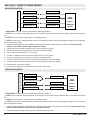
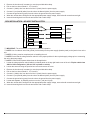
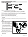
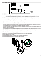
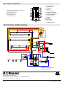
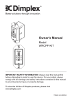
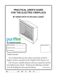
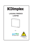
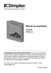
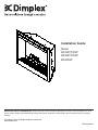
Installation Guide
Model
BF33STP/DXP
BF39STP/DXP
BF45DXP
IMPORTANT SAFETY INFORMATION: Always read this manual first before attempting to install or use this fireplace. For your
safety, always comply with all warnings and safety instructions contained in this manual to prevent personal injury or property
damage.
To view the full line of Dimplex products, please visit
www.dimplex.com
7206350500R03
Table of Contents
Listing and Code Approvals. . . . . . . . . . . . . . . . . . . . . . . . . . . . . . . . . . . . . . . . . . . . . . . . . . . . . . . . . . . . . . . . . . 3
Model Specifications. . . . . . . . . . . . . . . . . . . . . . . . . . . . . . . . . . . . . . . . . . . . . . . . . . . . . . . . . . . . . . . . . . . . . . . 3
Step-by-Step Installation . . . . . . . . . . . . . . . . . . . . . . . . . . . . . . . . . . . . . . . . . . . . . . . . . . . . . . . . . . . . . . . . . . . 3
Section A: Installation information . . . . . . . . . . . . . . . . . . . . . . . . . . . . . . . . . . . . . . . . . . . . . . . . . . . . . . . . . . . . 4
Framing Dimensions . . . . . . . . . . . . . . . . . . . . . . . . . . . . . . . . . . . . . . . . . . . . . . . . . . . . . . . . . . . . . . . . . . . . . . 4
Mounting Flanges . . . . . . . . . . . . . . . . . . . . . . . . . . . . . . . . . . . . . . . . . . . . . . . . . . . . . . . . . . . . . . . . . . . . . . . . 4
Section B: General Electrical Information. . . . . . . . . . . . . . . . . . . . . . . . . . . . . . . . . . . . . . . . . . . . . . . . . . . . . . 5
Recommended Power Supply Wire Specifications. . . . . . . . . . . . . . . . . . . . . . . . . . . . . . . . . . . . . . . . . . . . . . . 5
Voltage Selector Switch Location. . . . . . . . . . . . . . . . . . . . . . . . . . . . . . . . . . . . . . . . . . . . . . . . . . . . . . . . . . . . . 5
Section C: Direct Power Wiring. . . . . . . . . . . . . . . . . . . . . . . . . . . . . . . . . . . . . . . . . . . . . . . . . . . . . . . . . . . . . . . 6
240V Installation. . . . . . . . . . . . . . . . . . . . . . . . . . . . . . . . . . . . . . . . . . . . . . . . . . . . . . . . . . . . . . . . . . . . . . . . . . 6
120V Installation. . . . . . . . . . . . . . . . . . . . . . . . . . . . . . . . . . . . . . . . . . . . . . . . . . . . . . . . . . . . . . . . . . . . . . . . . . 6
120V Installation - No Heat Installation. . . . . . . . . . . . . . . . . . . . . . . . . . . . . . . . . . . . . . . . . . . . . . . . . . . . . . . . 7
Section D: Alternate Control Options. . . . . . . . . . . . . . . . . . . . . . . . . . . . . . . . . . . . . . . . . . . . . . . . . . . . . . . . . . 8
240V Main Power Wall Switch . . . . . . . . . . . . . . . . . . . . . . . . . . . . . . . . . . . . . . . . . . . . . . . . . . . . . . . . . . . . . . . 8
120V Main Power Wall Switch . . . . . . . . . . . . . . . . . . . . . . . . . . . . . . . . . . . . . . . . . . . . . . . . . . . . . . . . . . . . . . . 9
120V Main Power Wall Switch - No Heat. . . . . . . . . . . . . . . . . . . . . . . . . . . . . . . . . . . . . . . . . . . . . . . . . . . . . . 10
120V/240V Heater Wall Switch Control . . . . . . . . . . . . . . . . . . . . . . . . . . . . . . . . . . . . . . . . . . . . . . . . . . . . . . . 11
120V/240V Wall Mounted Thermostat . . . . . . . . . . . . . . . . . . . . . . . . . . . . . . . . . . . . . . . . . . . . . . . . . . . . . . . . 12
120V/240V Wall Mounted Flame Override Switch. . . . . . . . . . . . . . . . . . . . . . . . . . . . . . . . . . . . . . . . . . . . . . . 13
Wall Remote - WRCPF-KIT . . . . . . . . . . . . . . . . . . . . . . . . . . . . . . . . . . . . . . . . . . . . . . . . . . . . . . . . . . . . . . . . 14
Unit Internal Wiring Diagram . . . . . . . . . . . . . . . . . . . . . . . . . . . . . . . . . . . . . . . . . . . . . . . . . . . . . . . . . . . . . . . . 14
! NOTE: Procedures and techniques that are considered important enough to emphasize.
CAUTION: Procedures and techniques which, if not
carefully followed, will result in damage to the equipment.
Warning: Procedures and techniques which, if not
carefully followed, will expose the user to the risk of
fire, serious injury, or death.
2
www.dimplex.com
Listing and Code Approvals
The BF series fireplaces have been tested in accordance with the UL 2021 and CSA C22.2 No. 46 standards for fixed and
location-dedicated electric room heaters.
Model Specifications
Model
Number
Description
BF45DXP
45” Deluxe
BF39DXP
39” Deluxe
BF39STP
39” Standard
BF33DXP
33” Deluxe
BF33STP
33” Standard
Voltage
Rated
Power
(Watts)
120/120/
245/1440/
208/240
2100/2700
Current Draw (Amps)
Wall
Refractory
Remote
Control Thermostat Brick Look No Heat 120V 208V 240V
120V
Optional
Optional
Included
2.0
12.0
10.10
11.25
Included
2.0
12.0
10.10
11.25
N/A
2.0
12.0
10.10
11.25
Included
2.0
12.0
10.10
11.25
N/A
2.0
12.0
10.10
11.25
! NOTE: Power ratings shown include the light bulbs and motors (275 watts)
The installation of the fireplace unit must comply with the applicable Local and/or National Electrical Codes and utility requirements. This installation should be entrusted to duly qualified personnel where required by law.
Step-by-Step Installation
! NOTE: Please read all instructions before installing.
1. Rough in framing opening following the recommended dimensions located in Section A: Framing Dimensions.
2. Allow 8” (20.3 cm) of service cable for connecting power supply wire to junction box on fireplace when installing before
finishing wall. Allow up to 4’ (121.9 cm) of service cable for connecting power supply wire to junction box on fireplace
when installing after finishing wall. Remove the outer jacket and strip the individual conductors ½” (1.3 cm) from the end.
3. Loosen the screw securing the junction box cover and remove the cover.
4. Remove knockouts, if necessary, or use the provided cable clamp.
5. Place unit in position in the framed opening, level with shims if necessary and attach unit to frame using mounting flanges
provided (Figure 2).
6. Unit is factory wired for 208/240V power supply. If 120V operation is required, slide the switch and reconfigure the wiring
(Section C). Wires L1, L2, N & G are attached to the rear of the junction box cable clamp for easy access.
! NOTE: If wiring unit to operate with NO heat a dedicated circuit may not be required.
7. Wire a dedicated, properly fused circuit with a 15amp rating for the appropriate voltage (120V, 208/240V). See Section C
for factory setting wiring.
8. Make wall switch and or wall mounted thermostat connections as outlined in Section D.
9. Place all connectors inside the unit and secure the junction box cover to unit. Ensure that the cable clamp grips only the
jacket of service cable, thermostat and if applicable wall switch lines.
Warning: Ensure method of installation does NOT obscure the air intake slots on bottom front of unit in any manner.
(See diagram in Section A)
3
Section A: Installation information
Framing Dimensions
Model
BF45DXP
A
B
C
D
E
F
G
H
I
J
K
L
16.0”
45.5”
33.5”
30.1”
15.3”
42.0”
44.7”
22.8”
32.7”
60.0”
42.0”
42.0”
(40.5cm) (115.6cm) (85.1cm) (76.5cm) (38.9cm) (106.7cm) (113.5cm) (57.9cm) (83.1cm) (152.4cm) (106.7cm) (106.7cm)
BF39STP/DXP
16.0”
39.5”
33.5”
30.1”
15.3”
36.0”
(40.5cm) (100.3cm) (85.1cm) (76.5cm) (38.9cm) (91.4cm)
38.7”
22.8”
32.7”
54.0”
(98.3cm) (57.9cm) (83.1cm) (137.2cm)
38.0”
(96.5cm)
38.0”
(96.5cm)
BF33STP/DXP
15.0”
33.5”
29.5”
25.7”
14.3”
29.6”
(38.1cm) (85.1cm) (75.0cm) (65.3cm) (36.3cm) (75.2cm)
32.8”
18.8”
28.5”
48.0”
(83.3cm) (47.8cm) (72.4cm) (121.9cm)
34.0”
(86.4cm)
34.0”
(86.4cm)
Figure 1
K
L
J
Air Intake Slots
Rough-In Framing Dimensions
Firebox Dimensions
Rough-In Corner Framing
This fireplace is a zero clearance design. No combustibles can be placed on the top surface of the fireplace. Combustibles
may be installed to the edge of the unit. Four mounting flanges on the sides of the unit are provided to facilitate installation.
Insulation and vapor barrier should be placed a minimum of 2” (5.1 cm) from the unit.
Mounting Flanges
Figure 2
Mounting
Flanges
There are two mounting flanges located on each side of the fireplace insert.
From the inside of the unit, bend tabs outward and mount to the inside of the framing using suitable hardware.
4
www.dimplex.com
Section B: General Electrical Information
Recommended Power Supply Wire Specifications
For 120V installations use two conductor, non-metallic sheath cable with ground wire (3 wires total) for the incoming power
supply on fireplace inserts. Use the appropriate wire to meet local and national electrical codes for rated power consumption.
For 208V / 240V installations use three conductor, non-metallic sheath cable with ground wire (4 wires total) for the incoming power supply on fireplace inserts. Use the appropriate wire to meet local and national electrical codes for rated power
consumption.
Two conductor, non-metallic sheath cable with ground wire (3 wires total) is recommended for installation of a wall mounted
thermostat and/or wall switch for use on fireplace inserts. Use appropriate wire to meet local and national electrical codes for
rated power consumption. All wire gauges should match the recommended wire sizes shown below.
Voltage
Wire Gauge
Fuse Rating
120 Volts
12 Gauge
15 Amp
208 Volts
12 Gauge
15 Amp
240 Volts
12 Gauge
15 Amp
Voltage Selector Switch Location
! IMPORTANT: Ensure that the incoming power supply voltage matches the setting of the voltage selector switch.
! NOTE: The voltage selector switch is located inside the exhaust panel on the top right hand corner.
CAUTION: When changing the voltage selector switch from 240V to 120V ensure that the power supply is turned off.
! NOTE: Carefully insert a flat headed screwdriver inside the exhaust panel to change the switch from 240V (230 position)
to 120V (115 position).
When wiring the unit for 208V / 240V the voltage selector switch should be in the 230V position.
When wiring the unit for 120V the voltage selector switch should be in the 115V position.
5
Section C: Direct Power Wiring
FIREPLACE JUNCTION BOX
240V Installation
WHITE WIRE - N
WHITE WIRE - N
RED WIRE – L2
RED WIRE – L2
240 V
POWER
BLACK WIRE – L1
BLACK WIRE – L1
GREEN WIRE - G
GROUND WIRE - G
SUPPLY
(BREAKER
PANEL)
! IMPORTANT: The unit is factory configured for 208/240V operation.
! NOTE: Use 3 conductor wires with ground (4 wires total) from the power supply (breaker panel) to the junction box on the
unit.
! NOTE: All wiring must be completed prior to installing the unit.
! NOTE: Ensure that the voltage selector switch is in the proper position for the required supply voltage prior to connecting
the unit to the power supply.
1. Locate the voltage selector switch inside the exhaust panel on the top right hand corner of the unit. Ensure that the
switch is in the 240V position. (230 is printed on switch)
2. Loosen the screw securing the junction box cover and remove the cover.
3. Remove the knockouts (if necessary) or use the provided cable clamp.
4. Pull out the four wires marked L1, L2, N, and G.
5. Connect L1 (black) from the unit to the L1 (black) from the power supply.
6. Connect L2 (red) from the unit to the L2 (red) from the power supply.
7. Connect N (white) from the unit to the to the Neutral (white) from the power supply.
8. Connect the ground wire (green) from the unit to the ground from the power supply.
9. Ensure that all connections are tight.
10. Insert all the wiring back into the unit and secure with a cable clamp.
FIREPLACE JUNCTION BOX
120V Installation
WHITE WIRE - N
WHITE WIRE - N
RED WIRE – L2
BLACK WIRE – L1
GREEN WIRE - G
120 V
BLACK WIRE – L1
GROUND WIRE - G
POWER
SUPPLY
(BREAKER
PANEL)
! IMPORTANT: The unit is factory configured for 208/240V operation.
! NOTE: Use 2 conductor wires with ground (3 wires total) from the power supply (breaker panel) to the junction box on the
unit.
! NOTE: All wiring must be completed prior to installing the unit.
! NOTE: Ensure that the voltage selector switch is in the proper position for the required supply voltage prior to connecting
the unit to the power supply.
1. Locate the voltage selector switch inside the exhaust panel on the top right hand corner of the unit. Flip the switch from
240V to 120V configuration. (230 and 115 is printed on switch)
2. Loosen the screw securing the junction box cover and remove the cover.
6
www.dimplex.com
3.
4.
5.
6.
7.
8.
9.
Remove the knockouts (if necessary) or use the provided cable clamp.
Pull out the four wires marked L1, L2, N, and G.
Connect L1 (black) wire from the unit to the L1 (black) from the power supply.
Connect L2 (red) and N (white) from the unit to the Neutral (white) from the power supply.
Connect the ground wire (green) from the unit to the ground from the power supply.
When the unit has been configured for the appropriate power supply voltage, ensure that all connections are tight.
Insert all the wiring back into the unit and secure with a cable clamp.
120V Installation - No Heat Installation
FIREPLACE JUNCTION BOX
WHITE WIRE - N
WHITE WIRE - N
RED WIRE – L2
BLACK WIRE – L1
BLACK WIRE – L1
GREEN WIRE - G
GROUND WIRE - G
SUPPLY
(BREAKER
PANEL)
RED - 1
RED - 2
120 V
POWER
WIRE NUTS
! IMPORTANT: The unit is factory configured for 208/240V operation.
! NOTE: Use 2 conductor wires with ground (3 wires total) from the power supply (breaker panel) to the junction box on the
unit.
! NOTE: All wiring must be completed prior to installing the unit.
! NOTE: Ensure that the voltage selector switch is in the proper position for the required supply voltage prior to connecting
the unit to the power supply.
! NOTE: PurifireTM will operate without heat in this application.
1. Locate the voltage selector switch inside the exhaust panel on the top right hand corner of the unit. Flip the switch from
240V to 120V configuration. (230 and 115 is printed on switch)
2. Loosen the screw securing the junction box cover and remove the cover.
3. Remove the knockouts (if necessary) or use the provided cable clamp.
4. Pull out the four wires marked L1, L2, N, and G.
5. Connect L1 (black) wire from the unit to the L1 (black) from the power supply.
6. Connect L2 (red) and N (white) from the unit to the Neutral (white) from the power supply.
7. Connect the ground wire (green) from the unit to the ground from the power supply.
8. Locate and separate, by installing a wire nut on the 1 (red) and 2 (red).
9. When the unit has been configured for the appropriate power supply voltage, ensure that all connections are tight.
10. Insert all the wiring back into the unit and secure with a cable clamp.
7
Section D: Alternate Control Options
FIREPLACE JUNCTION BOX
240V Main Power Wall Switch
WHITE - N
WHITE – N
RED – L2
RED – L2
BLACK – L1
GROUND - G
WALL
SWITCH
240 V
POWER
BLACK – L1
SUPPLY
GROUND - G
(BREAKER
PANEL)
! NOTE: This option should not be used with the remote control kit.
! NOTE: Before installing the unit have the following wires installed:
1. A 3 conductor wire with ground (4 wires total) from the power supply panel to the main switch wall box.
2. A 3 conductor wire with ground (4 wires total) from the main switch wall box to the junction box on the unit.
! NOTE: Use a double pole, single throw (On/Off) wall switch that is rated for a minimum of 15 amps.
1. Locate the voltage selector switch inside the exhaust panel on the top right hand corner of the unit. Ensure that the
switch is in the 240V position. (230 is printed on switch)
2. Loosen the screw securing the junction box cover and remove the cover.
3. Remove the knockouts (if necessary) or use the provided cable clamp.
4. Pull out the four wires marked L1, L2, N, and G. (black, red, white and green)
5. Connect the L1 (black) wire from the unit to the L1 (black) wire from the main power wall switch by using a wire connector
(not supplied).
6. Connect other end of L1 (black) wire from the main power wall switch to the L1 terminal of the main power wall switch.
7. Connect the L2 (red) wire from the unit to the L2 (red) wire from the main power wall switch by using a wire connector
(not supplied).
8. Connect the other end of the L2 (red) wire from the main power wall switch to the L2 terminal of the main power wall
switch.
9. Connect the N (white) wire from the unit to the N
(white) wire from the main power wall switch by
using a wire connector (not supplied).
10. Connect the G (green) wire from the unit to the G
(green) wire from the main power wall switch by
using a wire connector (not supplied).
11. Connect the L1 wire from the power supply to the
L1 terminal of the main power wall switch.
12. Connect the L2 (black) wire from the power
supply to the L2 terminal of the main power wall
switch.
3 CONDUCTOR WIRE
13. Connect the N (white) wire from the power supply
FROM POWER SUPPLY
to the remaining N (white) wire from the unit by
using a wire connector.
3 CONDUCTOR WIRE
FROM MAIN SWITCH
14. Secure the 2 remaining G (green) wires with a
ground screw in the main switch wall box.
15. Ensure that all connections are tight.
16. Insert all the wiring of the main power wall switch
into the main switch wall box.
17. Insert all the wiring back into the unit and secure
with a cable clamp.
G FROM
POWER SUPPLY
G FROM
POWER SUPPLY
G FROM UNIT
L2 FROM
POWER SUPPLY
NEUTRAL FROM
UNIT AND SUPPLY
L1 FROM UNIT
G FROM UNIT
L1 FROM
POWER SUPPLY
L1 FROM
POWER SUPPLY
L2 FROM
POWER SUPPLY
L2 FROM UNIT
NEUTRAL FROM
UNIT AND SUPPLY
L1 FROM UNIT
N
L2 FROM UNIT
L2
L1
G
N
L2
L1
G
8
www.dimplex.com
120V Main Power Wall Switch
FIREPLACE JUNCTION BOX
WHITE - N
WHITE – N
RED – L2
120 V
BLACK – L1
POWER
WALL
SWITCH
GROUND - G
BLACK – L1
SUPPLY
GROUND - G
(BREAKER
PANEL)
! NOTE: This option should not be used with the remote control kit.
! NOTE: Before installing the unit have the following wires installed:
1. A 2 conductor wire with ground (3 wires total) from the power supply panel to the main switch wall box.
2. A 2 conductor wire with ground (3 wires total) from the main switch wall box to the junction box on the unit.
! NOTE: Use a single pole, single throw (On/Off) wall switch that is rated for a minimum of 15 amps.
1. Locate the voltage selector switch inside the exhaust panel on the top right hand corner of the unit. Ensure that the
switch is in the 120V position. (115 is printed on switch)
2. Loosen the screw securing the junction box cover and remove the cover.
3. Remove the knockouts (if necessary) or use the provided cable clamp.
4. Pull out the four wires marked L1, L2, N, and G (black, red, white and green).
5. Connect L1 (black) from the unit to the L1 (black) from the main power wall switch using a wire connector (not supplied).
6. Connect the other end of L1 (black) to the L1 terminal of the main power wall switch.
7. Connect L2 (red) from the unit and N (white) from the unit to the Neutral wire (white) of the main power wall switch by using a wire connector (not supplied).
8. Connect the other end of the N (white) to the Neutral wire (white) from the power supply panel by using a wire connector
(not supplied).
9. Connect Ground (green) from the unit to the Ground (green) wire of the main power wall switch by using a wire connector
(not supplied).
10. Connect L1 (black) wire from the power supply to the L1 terminal of the main power wall switch.
11. Secure the 2 remaining Ground wires (green) with a ground screw in the main switch wall box.
12. Ensure that all connections are tight.
13. Insert all the wiring of the main power wall switch into the main switch wall box.
14. Insert all the wiring back into the unit and secure with a cable clamp.
G FROM
POWER SUPPLY
G FROM UNIT
G FROM
POWER SUPPLY
G FROM UNIT
L1 FROM UNIT
L1 FROM UNIT
NEUTRAL FROM
UNIT AND SUPPLY
L1 FROM
POWER SUPPLY
NEUTRAL FROM
UNIT AND SUPPLY
N
L1 FROM
POWER SUPPLY
L2
L1
G
2 CONDUCTOR WIRE
FROM POWER SUPPLY
N
2 CONDUCTOR WIRE
FROM MAIN SWITCH
L2
L1
G
9
120V Main Power Wall Switch - No Heat
WHITE - N
FIREPLACE JUNCTION BOX
WHITE – N
RED – L2
BLACK – L1
120 V
WALL
SWITCH
RED – 2
RED – 1
GROUND - G
POWER
SUPPLY
BLACK – L1
(BREAKER
PANEL)
WIRE
NUTS
GROUND - G
! NOTE: This option should not be used with the remote control kit.
! NOTE: Before installing the unit have the following wires installed:
1. A 2 conductor wire with ground (3 wires total) from the power supply panel to the main switch wall box.
2. A 2 conductor wire with ground (3 wires total) from the main switch wall box to the junction box on the unit.
! NOTE: Use a single pole, single throw (On/Off) wall switch that is rated for a minimum of 15 amps.
1. Locate the voltage selector switch inside the exhaust panel on the top right hand corner of the unit. Ensure that the
switch is in the 120V position. (115 is printed on switch)
2. Loosen the screw securing the junction box cover and remove the cover.
3. Remove the knockouts (if necessary) or use the provided cable clamp.
4. Pull out the four wires marked L1, L2, N, and G (black, red, white and green).
5. Connect L1 (black) from the unit to the L1 wire (black) from the main power wall switch using a wire connector (not supplied).
6. Connect the other end of the L1 wire (black) to the L1 terminal of the main power wall switch.
7. Connect L2 (red) from the unit and the N (white) from the unit to the Neutral wire (white) of the main power wall switch by
using a wire connector (not supplied).
8. Connect the other end of the Neutral wire (white) to the Neutral wire (white) from the power supply panel by using a wire
connector (not supplied).
9. Connect the Ground wire (green) from the unit to the Ground wire (green) of the main power wall switch by using a wire
connector (not supplied).
10. Connect L1 (black) from the power supply to the L1 terminal of the main power wall switch.
11. Locate and separate by wire nut the 1 (red) and 2 (red).
12. Secure the 2 remaining Ground wires (green)
with a ground screw in the main switch wall
box.
13. Ensure that all connections are tight.
14. Insert all the wiring of the main power wall
switch into the main switch wall box.
15. Insert all the wiring back into the unit and secure with a cable clamp.
G FROM
POWER SUPPLY
G FROM
POWER SUPPLY
G FROM UNIT
G FROM UNIT
L1 FROM UNIT
L1 FROM UNIT
NEUTRAL FROM
UNIT AND SUPPLY
L1 FROM
POWER SUPPLY
NEUTRAL FROM
UNIT AND SUPPLY
N
L1 FROM
POWER SUPPLY
L2
L1
G
2 CONDUCTOR WIRE
FROM POWER SUPPLY
N
2
1
2 CONDUCTOR WIRE
FROM MAIN SWITCH
L2
L1
G
10
www.dimplex.com
FIREPLACE JUNCTION BOX
120V/240V Heater Wall Switch Control
RED – 2
WALL
SWITCH
RED – 1
GROUND - G
! NOTE: Before installing the unit complete the following:
1. Install main power connection with appropriate wiring - directly to the main power or through a wall switch.
2. Install a 2 conductor wire with ground (3 wires total) from the heater switch wall box to the junction box on the
unit.
! NOTE: Use a heater wall switch (On/Off) that is rated for a minimum of 15 amps.
1. Loosen the screw securing the junction box cover and remove the cover.
2. Remove the knockouts (if necessary) or use the provided cable clamp.
3. Pull out the three wires marked 1, 2, and G (red, red, and green).
4. Remove the wire connector and separate the wires marked 1 and 2.
5. Connect the 1 wire (red) from the unit to the L1 wire (black) from the heater wall switch by using a wire connector (not
supplied).
6. Connect the other end of L1 wire (black) from the heater wall switch to the L1 terminal of the heater wall switch.
7. Connect the 2 wire (red) from the unit to the Neutral wire (white) from the heater wall switch using a wire connector (not
supplied).
8. Connect the other end of the Neutral wire (white) from the heater wall switch to the L2 terminal of the heater wall switch.
9. Connect the Ground wire (green) from the unit to the Ground wire (green) from the heater wall switch using a wire connector (not supplied).
10. Secure the remaining Ground wire (green) with a ground screw in the heater switch wall box.
11. Ensure that all connections are tight.
12. Insert all the wiring of the heater wall switch into the heater switch wall box.
13. Insert all the wiring back into the unit and secure with a cable clamp.
G FROM
POWER SUPPLY
G FROM UNIT
G FROM UNIT
L1 FROM UNIT
WIRE 2 FROM
UNIT
NEUTRAL FROM
UNIT AND SUPPLY
L1 FROM
POWER SUPPLY
WIRE 1 FROM
UNIT
1
2
G
2 CONDUCTOR WIRE
FROM HEATER SWITCH
2
1
G
! NOTE: This only illustrates
heater switch connection,
see previous sections for
main power connection
instructions.
11
FIREPLACE JUNCTION BOX
120V/240V Wall Mounted Thermostat
RED – 2
WALL
THERMOSTAT
RED – 1
GROUND - G
! NOTE: Before installing the unit complete the following:
1. Install main power connection with appropriate wiring - directly to the main power or through a wall switch.
2. Install a 2 conductor wire with ground (3 wires total) from the thermostat wall box to the junction box on the unit.
! NOTE: Wiring of the thermostat must be completed prior to installing the unit.
! NOTE: The following installation instructions are for a single pole thermostat.
1. Loosen the screw securing the junction box and remove the cover.
2. Remove the knockouts (if necessary) or use the provided cable clamp.
3. Pull out the three wires marked 1, 2, and G (red, red, and green).
4. Remove the wire connector and separate the wires marked 1 & 2.
5. Connect the 1 wire (red) from the unit to the Neutral (white) wire from the wall thermostat box by using a wire connector
(not supplied).
6. Connect the other end of the Neutral (white) wire from the thermostat wall box to the red wire from the wall thermostat.
7. Connect the 2 wire (red) from the unit to the black wire from the thermostat wall box by using a wire connector (not supplied).
8. Connect the other end of the black wire from the thermostat wall box to the black wire from the wall thermostat.
9. Connect the Ground wire (green) from the unit to the Ground (green) wire from the thermostat wall box by using a wire
connector (not supplied).
10. Connect the other end of the Ground wire (green) to the thermostat wall box ground screw.
11. Ensure that all connections are tight.
12. Insert all the wiring of the wall mounted thermostat into the wall box.
13. Insert all the wiring back into the unit and secure with a cable clamp.
BLACK
RED
GROUND
BLACK
BLACK WIRE
RED
WHITE WIRE
GROUND
SCREW
GROUND
1
2
GROUND
G
! NOTE: This only illustrates
thermostat connection, see
previous sections for main
power connection instructions.
1
2
GROUND
G
12
www.dimplex.com
FIREPLACE JUNCTION BOX
120V/240V Wall Mounted Flame Override Switch
BLUE – 4
WALL
SWITCH
BLUE – 3
GROUND - G
DO NOT USE WITH NO HEAT INSTALLATIONS
! NOTE: The fireplace can be wired to have a wall switch operate the flame independent of the heater.
! NOTE: Before installing the unit complete the following:
1. Install main power connection with appropriate wiring - directly to the main power or through a wall switch.
2. Install a 2 conductor wire with ground (3 wires total) from the flame override switch wall box to the junction box
on the unit.
! NOTE: Use a wall switch (On/Off) that is rated for a minimum of 15 amps.
1. Loosen the screw securing the junction box cover and remove the cover.
2. Remove the knockouts (if necessary) or use the provided cable clamp.
3. Pull out the three wires marked 3, 4, and G (blue, blue, and green).
4. Remove the wire connector and separate the wires marked 3 and 4.
5. Connect 3 wire (blue) from the unit to the L1 wire (black) from the flame override wall switch by using a wire connector
(not supplied).
6. Connect the other end of the L1 wire (black) from the flame override wall switch to the L1 terminal of the flame override
wall switch.
7. Connect 4 wire (blue) from the unit to the Neutral wire (white) from the flame override wall switch using a wire connector
(not supplied).
8. Connect the other end of the Neutral wire (white) from the flame override wall switch to the L2 terminal of the flame override wall switch.
9. Connect the Ground wire (green) from the unit to the Ground wire (green) from the flame override wall switch using a wire
connector (not supplied).
10. Secure the remaining Ground wire (green) with a ground screw in the flame override switch wall box.
11. Ensure that all connections are tight.
12. Insert all the wiring of the heater wall switch into the heater switch wall box.
13. Insert all the wiring back into the unit and secure with a cable clamp.
G FROM UNIT
G FROM
POWER SUPPLY
G FROM UNIT
L1 FROM UNIT
WIRE 4 FROM
UNIT
NEUTRAL FROM
UNIT AND SUPPLY
L1 FROM
POWER SUPPLY
WIRE 3 FROM
UNIT
1
2
G
2 CONDUCTOR WIRE
FROM FLAME OVERRIDE SWITCH
4
3
G
! NOTE: This only illustrates
flame switch connection,
see previous sections for
main power connection
instructions.
13
Wall Remote - WRCPF-KIT
7
6
•
•
•
•
•
•
Can be used for 120V or 240V installations
Battery or 24V powered
50’ (15m) control range
Built in Thermostat
Flame On/Off Control
Heat On/Off Control
1
5
2
8
9
10
11
12
13
4
3
14
1.
2.
3.
4.
5.
6.
7.
8.
9.
10.
11.
12.
13.
14.
Room Temperature
Set Temperature
Flame Effect
Purifire™
Heat Off Indicator
Function Lock Indicator
RF Code Function Indicator
Set Temperature Down
Set Temperature Up
Flame Off
Flame On
Purifire™ Off
Purifire™ On
Low Battery Indicator
Unit Internal Wiring Diagram
! NOTE: Standard models
do not have a log driver
Dimplex North America Limited
1367 Industrial Road, Cambridge, ON, Canada N1R 7G8
© 2012 Dimplex North America Limited
14
www.dimplex.com