1
TM 05538C-10/1A
TM9-1005-319-10
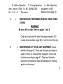
PAGES
2-6
9-15
28-34
35-40
41-42
44-45
6271
98-102
“MY RIFLE”
The creed of a United States Marine
by
Maj. Gen. W. H. Rupertus, USMC
This is my rifle. There are many like it, but this one is mine.
My rifle is my best friend. It is my life. I must master it as I must master my life.
My rifle, without me is useless. Without my rifle, I am useless. I must fire my rifle true. I must shoot
straighter than my enemy who is trying to kill me. I must shoot him before he shoots me. I will...
My rifle and myself know that what counts in this war is not the rounds we fire, the noise of our
burst, nor the smoke we make. We know that it is the hits that count. We will hit . . .
My rifle is human, even as I, because it is my life. Thus, I will learn it as a brother. I will learn its
weaknesses, its strength, its parts, its accessories, its sights, and its barrel. I will ever guard it
against the ravages of weather and damage. I will keep my rifle clean and ready, even as I am
clean and ready. We will become part of each other. We will ...
Before God I swear this creed. My rifle and myself are the defenders of my country. We are the
masters of our enemy. We are the saviors of my life.
So be it, until victory is America’s and there is no enemy, but Peace!
U.S. ARMY
CHANGE
No. 3
TM 9-1005-319-10
C3
HEADQUARTERS
DEPARTMENT OF THE ARMY
Washington D.C., 1 May 1994
Operator’s Manual
W/COMPONENTS LIST
RIFLE, 5.56-MM,
M16A2 W/E (1005-01-128-9936)
AND
CARBINE, 5.56-MM,
M4 W/E, (1005-01-231-0973)
TM 9-1005-319-10, August 1986, is changed to add M4A1 Carbine to this
TM. Changes are as follows:
1
Page Cover. Add "CARBINE, 5.56-MM, M4A1, (1005-01-382-0953)" to
cover.
Page 1. ALL WARNINGS in this technical manual pertain to all weapons
unless otherwise specified. Change the word rifle to "weapons", in all the
warnings unless otherwise specified.
Page 2. Add the following before the first paragraph:
"When a procedure is common to the rifle and both carbines, ONLY the
M16A2 rifle configuration will be depicted. If a procedure is not common to
all weapons, the procedure will be incorporated identifying the weapon(s)."
2
The M4 and M4A1 carbine buttstock has four positions; closed, 1/2 open,
3/4 open, and full open."
M4A1 is fully automatic.
Page 3. Add M4A1 information as follows:
Weight: 6.36 Ibs
Length: Buttstock closed 29.75 inches
Buttstock open 33.0 inches
Firing characteristics:
Muzzle velocity 2970 fps
Cyclic rate of fire 700-970 rounds per min
Max effective range:
500 meters (individual/point targets)
600 meters (area targets)
3
Page 3 (cont). Change M4 carbine weight to "3.32 Kg (7lb 5oz)".
Page 5. Add illustration of M4A1 upper receiver.
4
Page 6. Add the following note:
NOTE
M23 BFA is stamped "M4 Carbine Only", painted yellow and may
be used on the M4 and M4A1 carbines. M15A2 BFA is painted red
and used on the rifle.
Page 7. Add the following warning:
To be considered SAFE before disassembly, cleaning, inspecting,
transporting, or storing, the weapon must be cleared.
Page 11. Add the following caution:
Only use hand pressure to disengage the pivot and takedown pins.
Force other than hand pressure may cause damage to the weapon
and replacement of the weapon would be required. Only push the
pivot and takedown pins far enough to disengage the upper
receiver from the lower receiver.
5
Page 12. Add the following caution and procedure after step 11.
Do not fully remove the round nuts from the threaded studs. The
threaded studs are flared on the end to prohibit removal. However,
if the nuts are inadvertently removed, they may be reinstalled.
11.1. Loosen the round nuts on the left side of the carrying handle, approximately 4 turns. Loosen the clamping bar from the left side of the upper
receiver and lift off the carrying handle assembly.
6
Page 15. Add NOTE after step 21:
NOTE
The M4/M4A1 carbine has a four position buttstock; closed,
1/2 open, 3/4 open, and full open.
Page 16. Add the following:
"Wherever the term CLP or the words lube or lubricant are cited in this TM, it
is to be interpreted to mean that CLP, LSA, or LAW can be utilized as
applicable. DO NOT mix lubricants on the same weapon. The weapon must
be thoroughly cleaned during change from one lubricant to another. Dry
cleaning solvent (SD) is recommended for cleaning during change from one
lubricant to another."
Page 26. Add to the NOTE:
"If CLP is not used, RBC maybe used to remove carbon within the bore.
Dry cleaning solvent may be used to completely remove lubricants."
7
Page 28. Add "LSA - Lubricating oil, semifluid, 2 oz plastic bottle, NSN
9150-00-935-6597"
Page 29. Add lubricating procedures for M4A1 upper receiver and carrying
handle as follows:
1. Apply a drop or two of lubricant to both threaded studs.
2. Lightly lube the clamping bar and both round nuts.
3. Lightly lube the mating surfaces of the carrying handle assembly
and upper receiver.
Page 38. Add caution, note, reassemble procedure, and illustration after
step 8:
Should the round nuts and the clamping bar be inadvertently removed, the clamping bar must be reinstalled on
the threaded studs in a manner not to protrude past the
front of the carrying handle. The round nuts should be
reinstalled on the threaded studs.
8
NOTE
DO NOT ATTEMPT to reflare the end of the threaded stud
if the nuts have been removed.
“8.1. The carrying handle assembly should be reinstalled with the front stud
positioned into the first notch in the front of the upper receiver mounting
surface, Holding the carrying handle assembly flat against the top of the
upper receiver, slide the clamping bar against the receiver with the lower
edge underneath the slotted portion. Using finger pressure only, firmly
tighten both round nuts.”
9
Page 41, Add the following step before the NOTE:
“inspect feeder lips for damage. If damaged, replace magazine.”
Page 45, Add to the BURST paragraph “(M16A2 and M4 ONLY)”.
Add “AUTO” to the functional check as follows:
“AUTO (M4A1 ONLY) - Pull the charging handle to the rear, cocking the
weapon. Squeeze the trigger; hammer should fall. Hold the trigger to the
rear and cock the weapon. Fully release the trigger then squeeze it to the
rear again. The hammer should not fall because it should have fallen when
the bolt was allowed to move forward during the cocking sequence. ”
Add the following to the PMCS table:
UPPER RECEIVER - Carrying Handle Assembly
2.1
Check for missing or damaged parts and insure the handle
assembly will mount to the upper receiver.
Handle assembly is missing or has damaged parts,
or will not mount to upper receiver.
10
Page 47. Add Note under normal range paragraph:
NOTE
NORMAL RANGE M4A1 (300-600 METERS).
Page 50. Add "M16A2 ONLY" to the impact and distance columns in basic
TM. Add the following information to the impact and distance columns:
25 meters (M4/M4A1 ONLY)
1.2 cm (1/2 in)
100 meters (M4/M4A1 ONLY)
4.8 cm (1 7/8 in)
200 meters (M4/M4A1 ONLY)
9.6 cm (3 3/4 in)
Page 51. Add "M16A2 ONLY" to the impact and distance columns in basic
TM. Add the following information to the impact and distance columns:
25 meters (M4/M4A1 ONLY)
0.5 cm (3/16 in)
100 meters (M4/M4A1 ONLY)
1.9 cm (3/4 in)
200 meters (M4/M4A1 ONLY)
4.8 cm (1 1/2 in)
300 meters (M4/M4A1 ONLY)
5.7 cm (2 1/4 in)
400 meters (M4/M4A1 ONLY)
7.6 cm (3 in)
11
9.5 cm (3 3/4 in)
11.4 cm (4 1/2 in)
13.3 cm (5 1/4)
15.3 cm (6 in)
500
600
700
800
meters
meters
meters
meters
(M4/M4A1 ONLY)
(M4/M4A1 ONLY)
(M4 ONLY)
(M4 ONLY)
Page 56. Add to para 2., "600 meters maximum for M4A1."
Page 59. Add to first paragraph, second sentence, after 800 meters:,
"(M16A2 and M4) 500 or 600 meters (M4A1):
Para c, change the reference pages to "132-133"
Page 61. Add AUTO after burst paragraph:
"AUTO (M4A1 ONLY) - Carbine will continue to fire as long as the trigger is
pulled."
12
Page 83. Replace FM 3-87, FM 21-40 AND TM 3-220 with FM 3-3, FM 3-4,
FM 3-5, AND FM 3-100.
Page 86. Add after the first sentence in the Check For and What To Do
columns:
Notify unit armor.
Light indentation
on the primer.
Page 103. Replace FM’s 3-87, FM 21-40, and TM 3-220 with the following:
NBC Contamination Avoidance
FM 3-3
NBC Protection
FM 3-4
NBC Decontamination
FM 3-5
NBC Defense, Chemical Warfare, Smoke,
FM 3-100
and Flame Operations
Operator’s Manual for Decontaminating Kit,
TM 3-4230-216-10
Skin: M258A1 and Training Aid, Skin Decontaminating: M58A1
13
Page 122. Add the word “Red” after (M16A2 only) for the blank firing
attachment, M15A2.
Add “(M4A1) and the word Yellow” after (M4 Carbine) for the blank firing
attachment, M23.
Page 123. Add the following item to the AAL:
8465-00-781-9564
CASE, MAINTENANCE EQUIPMENT: for
weapons wit bout buttstock stowage
(81349) MIL-C-43737
(CARBINE ONLY)
Page 129. Add the following items to the expendable list:
2.1 C 6850-00-224-6656 CLEANING COMPOUND, RIFLE BORE: OZ
small arms bore cleaning solution
(RBC) (81349) MIL-C-372
2 oz (59.15 ml) bottle
14
3.1 O 6850-00-281-1985 DRY CLEANING SOLVENT:
(58536) A-A-711
1 gal. (3.79 I) can
Page 130/(1 31 blank). Add the following item to the expendable list:
4.1
LUBRICATING OIL, WEAPONS: (LSA),
semifluid (81 349) MIL-L-46000
C 9150-00-935-6597
2 oz (59.1 5 ml) plastic btl
C 9150-00-889-3522
4oz(118.30 ml) plastic btl
OZ
OZ
Page 132 and 133. Chart
15
By Order of the Secretary of the Army:
GORDON R. SULLIVAN
General, United States Army
Chief of Staff
Official:
MILTON H. HAMILTON
Administrative Assistant to the
Secretary of the Army
06646
To
DISTRIBUTION:
DA Form 12-40-E,
9-1005-319-10.
be distributed in accordance with
Block 0016 requirements for TM
U.S. ARMY
CHANGE
NO. 2
TM 9-1005-319-10
C2
HEADQUARTERS
DEPARTMENT OF THE ARMY
Washington,
DC
23
June
1993
Operator's Manual
W/COMPONENTS LIST
RIFLE, 5.56-MM,
M16A2 W/E
(1005-01-128-9936
TM 9-1005-319-10, August 1986, is changed to add the M4 Carbine to this
TM. Changes are as follows:
Page Cover. Add "CARBINE, 5.56-MM, M4 W/E, (1005-01-231-0973)" to
cover.
1
Page 1. Add the following WARNING:
Be sure to clear weapon before disassembly, cleaning, inspecting,
transporting, or storing.
Page 2. Add to the header after RIFLE, "/CARBINE".
Add before the first paragraph:
When a procedure is common to M16A2 rifle and M4 carbine, ONLY the
M16A2 configuration will be depicted. If a procedure is not common to both
weapons, the procedure will be incorporated.
2
Add illustration of Carbine to this page.
Page 3. Add the word "loaded" to the rifle information on line four before the
word rounds.
Add carbine information as follows:
Weight: W/30 (loaded) rounds mag 3.31 Kg (7.5 lb)
Length: Buttstock closed 29.75 inches
ButtStock open 33.0 inches
3
Firing characteristics:
Muzzle velocity 2970 fps
Cyclic rate of fire 700-900 rounds per min
Max effective range:
500 meters (individual/point targets)
800 meters (area targets)
Change Max range 3534 meters to 3600 (for rifle and carbine)
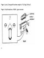
Page 4. Add illustration of carbine buttstock to show lock release lever of
4
Page 6. Add “/M23" to the header after M15A2.
Page 9. Replace buttstock w/sling illustration with the following and add
illustration of M4 Carbine sling:
Page 10. Add caution berfore the NOTE.
Do not use a screwdriver or any other tool when removing the
handguards. Doing so may damage the handguard and/or
SIipring.
5
Page 15. Add the following steps as follows:
"CARBINE ONLY
21 Extend buttstock assembly.
22 Grasp the lock release lever in the area of the retaining nut, pull downward, and slide buttstock to the rear to separate the buttstock assembly
from the lower receiver extension. "
6
Page 22. Add "Clean carbine lower receiver extension and buttstock."
Page 28. Lube guide change “0 F AND -35 F" to "+10 F AND - 10 F".
Change the thermometer to correspond with the text.
7
Page 35. Add to reassembly before step 1:
"Grasp the lock release lever in the area of the retaining nut and pull to
reinstall the buttstock assembly onto the lower receiver extension."
8
Page 40. Replace buttstock illustration with the following and add illustration
of sling being put on carbine.
9
Page 45. Add the Operator Preventive Maintenance Checks and Service
(PMCS):
Before starting an inspection, be sure to clear the rifle (p. 7).
Do not squeeze the trigger until the rifle has been cleared.
Inspect the chamber to ensure that it is empty and no
ammunition is in position to be chambered. Do not keep live
ammunition near work area.
D - During Operation
A - After Operation
B - Before Operation
Equipment is NOT
Item Interval ITEM TO BE lNSPECTED
READY/AVAlLABLE IF:
Procedure
No. B D A
1
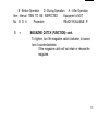
MAGAZINE.
a. Magazine slips easily into the magazine well and
locks in place.
Magazine is distorted or is hard to seat in magazine
well.
10
A - After Operation
B - Before Operation
D - During Operation
Item Interval ITEM TO BE INSPECTED
Equipment is NOT
No. B D A
Procedure
READY/AVAlLABLE IF:
b. Magazine follower has spring tension and moves easily
inside of magazine.
Magazine follower is stuck or has weak spring
tension.
2
UPPER RECEIVER - Barrel
Check for barrel looseness (using hand pressure only).
Barrel is loose enough to be moved by hand.
3
LOWER RECEIVER - Magazine Catch. Check magazine catch for spring tension and retention of magazine.
(NOTE: Perform this check with the rifle assembled).
Magazine catch has no spring tension or does not
retain magazine.
11
D - During Operation
A - After Operation
B - Before Operation
Equipment is NOT
Item Interval ITEM TO BE INSPECTED
No. B D A
Procedure
READY/AVAlLABLE IF:
4
RIFLE SIGHTS (ZERO ADJUSTMENT). Move front and
rear sight to make sure they can be adjusted. Return
sights to zero setting of your rifle.
If the sights are damaged, missing, or can’t be
adjusted.
5
MAGAZINE CATCH (FUNCTION). Insert magazine into the
well. The magazine catch should hold the magazine in
place. Pressing the magazine catch button should release
the magazine. To adjust the magazine catch, use cleaning
rod to press in on the magazine catch button until the left
side of the magazine catch sticks out beyond the receiver.
12
B - Before Operation
D - During Operation
A - After Operation
Equipment is NOT
Item Interval ITEM TO BE INSPECTED
READY/AVAILABLE IF:
Procedure
No. B D A
5
MAGAZINE CATCH (FUNCTION)--cont.
To tighten, turn the magazine catch clockwise; to loosen,
turn it counterclockwise.
If the magazine catch will not retain or release the
magazine.
13
ltem
No.
6
A - After Operation
B - Before Operation
D - During Operation
Equipment is NOT
Interval ITEM TO BE INSPECTED
READY/AVAILABLE IF:
Procedure
B D A
VISUAL INSPECTION OF RIFLE.
Be sure rifle is clear. Refer to pages 7 and 8.
Look the rifle over for missing or damaged parts. Report
missing or damaged parts to unit armorer.
Parts are missing or damaged to a point of being
unserviceable.
7
14
PERIODIC INSPECTION OF RIFLE. Periodically check rifle
to make sure it’s clean and there is no foreign material in
bore. If foreign material is in bore, clean bore (page 76).
If foreign material is in bore.
D - During Operation
A - After Operation
B - Before Operation
Item Interval ITEM TO BE INSPECTED
Equipment is NOT
READY/AVAlLABLE IF:
No. B D A
Procedure
8
MAINTENANCE PERFORMED DURING FIRING OPERATIONS
Be sure rifle is clear. Refer to pages 7 and 8.
Clean and lubricate rifle after firing approximately 200
rounds of ammunition (page 29) or at the end of the day.
9
MAINTENANCE OF RIFLE AND EQUIPMENT. Disassemble rifle (page 9). Clean and lubricate according to
pages 16 thru 34. Disassemble magazine. Clean and
lubricate according to page 41. Clean and lubricate
bayonet and scabbard. Report all damaged or missing
parts to unit armorer.
15
Page 45. Add the word "slowly" after the fourth sentence, "Pull charging.
. . . . . . . .release slowly. "
Change the next sentence to read
or hesitations. Pull the trigger."
"Slowly release the trigger without stops
Add NOTE after SEMI paragraph:
NOTE
Slow is defined as 1/4 to 1/2 the normal rate of trigger release.
Change the wording in BURST paragraph, fifth sentence, to read, "Pull
charging handle to rear and release three times.
Page 52-55. Delete "U.S. MARINE CORPS" from each page because
Army will use this information.
16
Page 53. Add to step 4, after the second sentence, "ARMY rifles will have
the 300 meter mark set on the last whole click before it bottoms out.
Page 71. Add after header, "Your weapon is now combat ready; e.g.,
ammunition loaded, bolt forward, and safety on."
Page 119. Add two slings as follows:
3 1005-01-216-4510 SLING, SMALL ARMS (M16A2)
(19204) 12624561
EA
1
4 1005-01-368-9852 SLING, SMALL ARMS (M4 Carbine)
(19200) 12011996
EA
1
Page 122. Add after BFA, M15A2: "(M16A2 Only)".
17
1005-01-361-8208
BLANK FIRING ATTACHMENT, M23: (M4 Carbine)
(For Training Only)
(19200) 12597837
Page 124. Change the quantity "1" for the magazine, cartridge to "6".
18
By Order of the Secretary of the Army:
GORDON R. SULLIVAN
General, United States Army
Chief of Staff
Official:
MILTON H. HAMILTON
Administrative Assistant to the
Secretary of the Army
DISTRIBUTION:
To
DA
Form
12-40-E,
TM
9-1005-319-10.
be
distributed
Block
0016,
in
accordance
requirements
for
with
By Order of the Marine Corps:
H. E. REESE
Deputy for Support
Marine Corps Research, Development
and Acquisition Command
By Order of the Secretary of the Army:
OFFICIAL:
CARL E. VUONO
General, United States Army
Chief of Staff
WILLIAM J. MEEHAN II
Brigadier General, United States Army
The Adjutant General
DISTRIBUTION:
To be distributed in accordance with DA Form 12-40E (Block 16), Operator
Maintenance Requirements for TM 9-1005-319-10.
For information on First aid,
see FM 21-11.
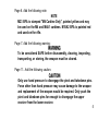
BEWARE OF DANGEROUS PROCEDURES
sure the cam pin is installed in the bolt group. If it isn’t, your rifle can st ill fire and will explode,
● Be
● If
you’re using the blank firing attachment, don’t use any other ammo except the blank round
M200 (marked on each box of 20 rounds).
• DO NOT exchange or switch bolt assemblies from one M16A2 to another. Doing so may result in
injury to, or death of, personnel.
• If your rifle stops firing with a live round in the chamber of a hot barrel (misfire), remove the round
fast. However, if you cannot remove it within 10 seconds, remove magazine and wait 15 minutes
with the rifle pointing in a safe direction. This way you won’t get hurt by a possible round
cooking-off. Regardless, keep your face away from the ejection port while clearing a hot
chamber.
● Use only authorized ammo that is manufactured to U.S. or NATO specifications.
● If
your bolt fails to unlock and you try to free it by banging the buttstock on the ground keep
yourself clear of the muzzle,
● If there’s water in the barrel, don’t fire the rifle. It could explode.
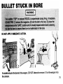
• If a noticeable difference in sound or recoil is experienced, STOP FlRING. Either condition could
indicate an incomplete powder burn and/or a bullet stuck in the bore
1
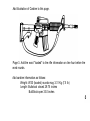
FACTS ABOUT YOUR RIFLE
The M16A2 rifle system consists of a rifle, a magazine, and a sling. It is a lightweight, gasoperated, air-cooled, magazine-fed, shoulder-fired weapon that can be fired either in automatic
three-round bursts or semiautomatic single shots. Other features:
● Upper receiver and barrel assembly has a fully adjustable rear sight and a compensator that
helps keep the muzzle down during firing.
● Upper and lower receivers are easily opened for cleaning and inspection.
● Bolt
group and barrel extension are designed with locking lugs that lock bolt group to barrel
extension.
● An aluminum receiver reduces the weight of the rifle.
● The
2
bore and chamber are chrome plated.
Caliber:
5.56 mm
Weight:
W/30 rounds mag 3.99 Kg (8.79 lb) approx
Length:
Rifle w/compensator 39 5/8 inches
Mechanical features:
Rifling (RH 1/7 twist)
Firing characteristics:
Muzzle velocity (approx) 3,100 fps
Chamber pressure 52,000 psi
Cyclic rate of fire (approx) 800 rounds per min
Max effective rates of fire:
Semi : 45 rounds per min
Burst: 90 rounds per min
Sustained rate of tire:
12/1 5 rounds per min
Max effective range:
550 meters (individual/point targets)
800 meters (area targets)
Max range:
3534 meters
3
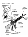
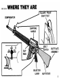
RIFLE
4
PARTS
AND
.
.
.
5
6
7
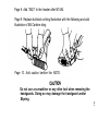
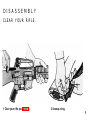
CLEAR
YOUR
3 To lock bolt open, pull charging handle rearward. Press
bottom of bolt catch and allow
bolt to move forward until it
engages bolt catch. Return
charging handle to forward. If
you haven’t before, place
selector lever on SAFE.
4 Check receiver and chamber
to ensure these areas contain
no ammo.
5 With selector lever pointing
toward SAFE, allow bolt to go
forward by pressing upper
portion of bolt catch.
8
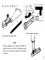
RIFLE
(CONT)
DISASSEMBLY
CLEAR YOUR RIFLE.
1 Clear your rifle (see page 7).
2 Unsnap sling.
9
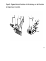
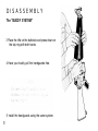
DISASSEMBLY
The "BUDDY SYSTEM"
3 Place the rifle on the buttstock and press down on
the slip ring with both hands.
4 Have your buddy pull the handguards free.
5 Install the handguards using the same system.
10
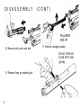
7 Push receiver pivot pin.
8 Seperate upper and lower receivers.
9 Pull back charging handle and bolt carrier.
11
DISASSEMBLY
10 Remove bolt carrier and bolt.
(CONT)
11 Remove charging handle.
DO NOT OPEN OR
CLOSE SPLIT END
12 Remove firing pin retaining pin.
12
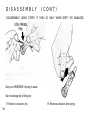
DISASSEMBLY
(CONT)
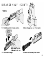
13 Put bolt assembly in locked position.
14 Drop firing pin out rear of bolt carrier.
15
16 Remove bolt assembly from carrier.
Remove bolt cam pin.
13
DISASSEMBLY
(CONT)
DISASSEMBLE USING STEPS 17 THRU 20 ONLY WHEN DIRTY OR DAMAGED.
See your ARMORER if spring is weak.
Do not damage tip of firing pin.
17 Remove extractor pin.
14
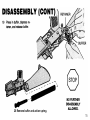
18 Remove extractor and spring.
20 Remove buffer and action spring.
15
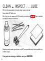
CLEAN
■■
. INSPECT . . . LUBE
With the rifle disassembled, thoroughly clean, inspect, and lube.
Always shake CLP before use.
After firing, clean your weapon with CLP according to instructions on page 26. Wipe dry and lube
according to lubrication instructions.
Cleaning materials: swabs, pipe cleaners, and CLP are expendable items that are available from
Company Supply.
If any parts are missing or defective, see your ARMORER.
16
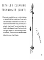
DETAILED
CLEANING
TECHNIQUES
Don’t mix up the parts of your rifle with those
of your buddy.
BORE. The bore of your M16A2 has lands and grooves
called riling.Rifling makes the bullet spin very fast as it moves
down the bore and down range. Because it twists so quickly, it
is difficult to push a new, stiff bore brush through the bore. You
will find it muich easier to pull your bore brush through the
bore. AIso, because the brush will clean better if the bristles
follow the grooves (called tracking), you want the bore brush to
be allowed to turn as you pull it through. This is how you do it:
1 Swab out the bore with a patch moistened with CLP.
2 Attach three rod sections together but leave each one
about two turns short of being tight.
3 Attach the bore brush but leave it two turns short also.
This whole process will go quicker if you use
the “buddy system” on the cleaning rods.
Set one rod up with a patch holder and the
other with a bore brush.
17
DETAILED
CLEANING
TECHNIQUES
18
(CONT)
4
Point muzzle down. Hold the upper receiver in one hand
while inserting the end of the rod without the brush into
the chamber. Let the rod fall straight through the bore.
About 2-3 inches will be sticking out of the muzzle at this
point.
5
Attach the handle section of the cleaning rod to the end of
the rod sticking out of the muzzle.
6
Pull the brush through the bore and out the muzzle. If you
watch closely, you can see the rod twisting as you pull it.
7
After one pull, take off the handle section and repeat the
process. After three or four pulls, you will see that the three
rod sections and the bore brush are screwing together.
Loosen them up and repeat the process.
DETAILED
CLEANING
TECHNIQUES
(CONT)
8 Send a patch through the bore once in a while to help clean
out the crud that the brush is getting loose. You can use the
same technique as described above to save time. Just
replace the bore brush with the rod tip (patch holder) and a
wet patch. Drop it through. You won’t need to attach the
handler to pull only a patch through. If you leave the rods
loose again, the patch will “track’ in the rifling as before.
But remember, always have the bore wet with cleaner
before trying to pull a brush through.
19
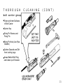
THOROUGH
upper receiver
CLEAN WITH CLP
All Areas of
Powder Fouling,
Corrosion, Dirt,
and RUST
Bore and
Chamber
Locking Lugs
Gas Tube
START AT
RECEIVER AND
DROP ROD AND
BRUSH THROUGH.
ATTACH HANDLE AND
PULL THROUGH THE
COMPENSATOR.
20
CLEANING
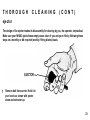
T H O R O U G H
C L E A N I N G
( C O N T )
bolt carrier group
Outer and Inner Surfaces
of Bolt Carrier
Carrier Key
Firing Pin Recess and
Firing Pin
Firing Pin Hole (Use Pipe
Cleaner.)
Carbon Deposits and Dirt
from Locking Lugs
Areas Behind Bolt Ring
and Under Lip of Extractor
21
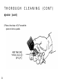
THOROUGH
CLEANING
lower receiver group
All Areas of Powder Fouling, Corrosion,
and Dirt.
Wipe Dirt from Trigger Mechanism.
Clean Buffer, Action Spring, and Inside
Lower Receiver Extension.
22
(CONT)
THOROUGH
CLEANING
(CONT)
ejector
The design of the ejector makes its disassembly for cleaning by you, the operator, impractical.
Make sure your M16A2 ejects those empty cases clear of you and your rifle by following these
steps on a monthly or as required (weekly if firing blanks) basis.
Remove bolt from carrier. Hold it in
your hands as shown with ejector
down and extractor up.
23
THOROUGH
CLEANING
ejector (cont)
2 Place a few drops of CLP around the
ejector to form a puddle.
24
(CONT)
THOROUGH
CLEANING
(CONT)
ejector (cont)
3
Take a fired or dummy case and place it
under the lip of the extractor. With a rocking
motion, press the case down against the
ejector. Since the ejector is spring loaded,
some resistance will be felt. Press on the
case until it stops against the bolt face.
Ease off with your thumb slightly and press
down again. Repeat several times.
Replace the CLP frequently. Once the
spring action of the ejector is smooth and
strong, dry off any excess.
25
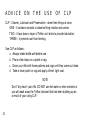
ADVICE
ON
THE
USE
OF
CLP
CLP - Cleaner, Lubricant and Preservative - does three things at once:
ONE - It contains solvants to dissolve firing residue and carbon.
TWO - It lays down a layer of Teflon as it dries to provide lubrication.
THREE - It prevents rust from forming.
Use CLP as follows:
a. Always shake bottle well before use.
b. Place a few drops on a patch or rag.
c. Clean your rifle with these patches and rags until they come out clean.
d. Take a clean patch or rag and apply a fresh, light coat.
NOTE
Don’t “dry clean” your rifle. DO NOT use hot water or other solvents or
you will wash away the Teflon lubricant that has been building up as
a result of your using CLP.
26
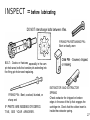
INSPECT =
before lubricating
DO NOT interchange bolts between rifles.
FIRING PIN RETAINING PIN Bent or badly worn
BOLT - Cracks or fractures, especially in the cam
pin hole area; bolts that contain pits extending into
the firing pin hole need replacing.
FIRING PIN - Bent, cracked, blunted, or
sharp end
IF PARTS ARE MISSING OR DEFECTIVE, SEE YOUR ARMORER.
EXTRACTOR AND EXTRACTOR
SPRING
Check extractor for chipped or broken
edges in the area of the lip that engages the
cartridge rim. Check that the rubber insert is
inside the extractor spring.
27
LUBE
GUIDE
Under all but the coldest Arctic conditions, CLP is the lubricant
to use on your rifle. Remember to remove excessive CLP from
the bore and chamber before tiring.
CLP
- Cleaner, lubricant and preservative
Refillable 1/2 oz bottle
NSN 9150-01-102-1473
BETWEEN 0°F AND -35°F EITHER CLP OR LAW
LAW
- Lubricating oil, Arctic weapons
1 qt can
NSN 9150-00-292-9689
Lightly Lubed
- A film of CLP barely visible to the eye
Generously Lubed
28
- Heavy enough so that it can be spread
with the finger
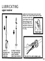
LUBRICATING
upper receiver
Lightly lube inside of upper receiver, bore and
chamber, outer surfaces of barrel and front sight,
and surfaces under handguard. Depress front sight
detent and apply two or
three drops CLP to front
sight detent. Depress several times to work lube into
the spring.
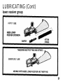
LUBRICATING (Cont)
30
LUBRICATING (Cont)
lower receiver group
31
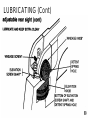
LUBRICATING (Cont)
adjustable rear sight
NOTE
Make a note of how far you move the sights so they can be returned to
their original position at completion of this task.
MOVING PARTS. Use one or two drops of CLP. Rotate these parts (see page 33) to ensure
lubricant is spread evenly above and below:
a. Elevation knob
b. Elevation screw shaft
c. Windage knob (maximum five clicks left or right)
d. Windage screw
e. Detent holes
32
ELEVATION SCREW SHAFT. Also lube from inside the upper receiver as follows:
a. Turn upper receiver upside down.
b. Remove charging handle.
c. Put two or three drops on bottom of elevation screw shaft and in elevation detent spring hole.
d. Rotate the elevation dial back and forth a few times while keeping upper receiver upside
down.
LUBRICATING (Cont)
33
LUBRICATING (Cont)
adjustable rear sight (cont)
AFTER LUBING REAR SIGHT:
a. Reset your correct zero windage and your battlesight zero. Refer to pages 48-51.
b. Notice the rear sight comes down when the “3” is aligned with the mark on the
left side of the receiver.
c. You will feel a “click" when the “3” first lines up with the mark.
d. Carry your rifle with the “3” aligned with the mark.
e. Keep the sight on 300 meters to keep dirt and water out of sight mechanism and protect the
sight from damage.
AFTER AMPHIBIOUS OPERATIONS:
a. Clean your rear sight as soon as possible if it has salt water on it.
b. Wash your rear sight with fresh water from your canteen or some other source if you don’t
have time to clean it with CLP right away.
34
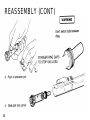
R E A S S E M B L Y
2 Insert extractor and spring.
1 Insert action spring and buffer.
NOTE
Extractcr assembly has a rubber insert within the
spring. Be sure not to lose it. If the spring comes
loose, put the large end of spring in the extractor
and seat it.
35
REASSEMBLY (CONT)
36
REASSEMBLY (Cont)
Be sure the cam pin is installed in the bolt group. If
it isn’t, your rifle cart still fire and will explode.
5 Replace bolt cam- pin.
7 Pull bolt out.
37
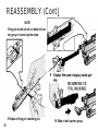
REASSEMBLY (Cont)
NOTE
Firing pin should not fall out when bolt carrier group is turned upside down.
8 Replace firing pin retaining pin.
38
10 Slide in bolt carrier group.
REASSEMBLY (Cont)
39
REASSEMBLY (Cont)
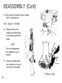
14 Close upper and lower receiver groups.
Push in takedown pin.
THE “BUDDY SYSTEM”
15
Place the rifle on the
buttstock and press down
on the slip ring with both
hands.
NOTE
The round handguards
are indentical (top or
bottom).
16
Have your buddy install
one handguard on top and
the other on the bottom.
17 Snap on sling.
40
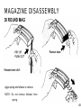
MAGAZINE DISASSEMBLY
30 ROUND MAG
Jiggle spring and follower to remove.
NOTE: Do not remove follower from
spring.
41
MAGAZINE REASSEMBLY
IF THE SPRING COMES LOOSE FROM THE
FOLLOWER, TURN IN THE PIECES. DON’T
TRY TO FIX IT YOURSELF.
CLEAN AND LUBE
Wipe dirt from tube, spring, and follower; then
lightly lube spring.
Slide the base under all four tabs until base
catches.
MAKE SURE PRINTING IS ON THE
OUTSIDE.
42
Insert follower and jiggle
spring to install.
THIS PAGE INTENTIONALLY LEFT BLANK
43
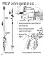
PMCS* before operation and . . .
44
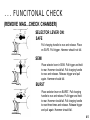
. . . FUNCITONAL CHECK
(REMOVE MAG...CHECK CHAMBER)
SELECTOR LEVER ON:
SAFE
Pull charging handle to rear and release. Place
on SAFE. Pull trigger. Hammer should not fall.
SEMI
Place selector lever in SEMI. Pull trigger and hold
to rear. Hammer should fall. Pull charging handle
to rear and release. Release trigger and pull
again. Hammer should fall.
BURST
Place selector lever on BURST. Pull charging
handle to rear and release. Pull trigger and hold
to rear. Hammer should fall. Pull charging handle
to rear three times and release. Release trigger
and pull again. Hammer should fall.
45
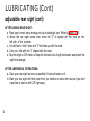
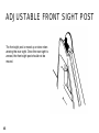
ADJUSTABLE FRONT SIGHT POST
The front sight post is moved up or down when
zeroing the rear sight. Once the rear sight is
zeroed, the front sight post should not be
moved.
46
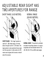
ADJUSTABLE REAR SIGHT HAS
TWO APERTURES FOR RANGE
SHORT RANGE (0-200 METERS)
SHORT RANGE - This “larger” aperture is
used for 0 - 200 meters range. As shown
above, the sight is set for 0 - 200 meters. This
larger aperture is only used when the rear sight
is all the way down. In other words, the 300meter mark is aligned with the mark on the left
side of the receiver.
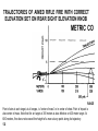
NORMAL RANGE
(300-800 METERS)
NORMAL RANGE - The aperture is unmarked
and used for most firing situations. It is used in
conjunction with the elevation knob for 300,
400, 500, 600, 700, and 800 meter targets.
47
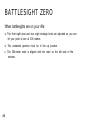
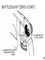
BATTLESIGHT ZERO
When battlesights are on your rifle:
a. The front sight post and rear sight windage knob are adjusted so you can
hit your point of aim at 300 meters.
b. The unmarked aperture must be in the up position.
c. The 300-meter mark is aligned with the mark on the left side of the
receiver.
48
BATTLESIGHT ZERO (CONT)
49
BATTLESIGHT ZEROING
ADJUSTMENTS
a.
During zeroing procedures, only the front sight post and windage knob are adjusted to move
the strike of the bullet on the target.
b.
If you are zeroing on a 25-meter range, the rear sight elevation knob is adjusted to the
300-meter mark plus one "click" up.
c.
Detailed zeroing procedures are on the following pages 52-55.
FRONT SIGHT. To adjust elevation, depress
detent and rotate post. To raise strike of bullet, rotate
post in the direction of arrow marked UP. Reverse
the direction of rotation to lower strike of bullet. Each
graduation (notch) moves the point of impact of bullet
as indicated.
IMPACT
0.9 cm (3/8 in.)
3.5 cm (1 3/8 in.)
7.0 cm (2 3/4 in.)
50
DISTANCE
25 meters
100 meters
200 meters
BATTLESIGHT ZEROING
*All the above values have been rounded off.
To remember your correct battlesight zero windage, note location of windage scale and windage
knob pointer (heavy mark on outside of knob).
Do not center rear sight aperture for inspections. Keep your correct battlesight zero windage on the
rifle at all times.
51
52
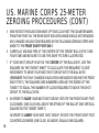
U.S. MARINE CORPS TARGET
U.S. MARINE CORPS 25-METER
ZEROING PROCEDURES
(BY FOLLOWING THE STEPS BELOW AND ESTABLISHING A ZERO AT 25 METERS, YOUR
M16A2 RIFLE SIGHTS WILL BE SET WITH A 300-METER BATTLESIGHT.)
1
DO NOT MOVE FRONT SIGHT POST AT THIS TIME. IT WAS SET AT THE FACTORY OR
BY A PREVIOUS SHOOTER AND SHOULD BE VERY CLOSE TO YOUR ZERO.
2 CENTER THE REAR SIGHT APERTURE BY TURNING THE WINDAGE KNOB LEFT OR
RIGHT. (THIS IS CALLED MECHANICAL ZERO WINDAGE.)
3 THE UNMARKED APERTURE SHOULD BE UP.
4 ROTATE ELEVATION KNOB IN THE DOWN DIRECTION (COUNTER-CLOCKWISE).
THE ELEVATION KNOB SHOULD STOP THREE CLICKS PAST THE 300-METER
MARK. THE REAR SIGHT SHOULD BE ALL THE WAY DOWN ON THE LAST
WHOLE “CLICK” BEFORE IT BOTTOMS OUT. THIS IS CALLED MECHANICAL
ZERO ELEVATION FOR THE REAR SIGHT. IF YOUR RANGE SCALE WILL NOT
LINE UP IN THE ABOVE MANNER, AN ARMORER WILL BE REQUIRED TO
ADJUST THE RANGE SCALE FOR YOU.
53
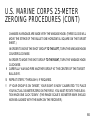
US. MARINE CORPS 25-METER
ZEROING PROCEDURES (CONT)
5
6
NOW ROTATE THE ELEVATION KNOB "UP" ONE CLICK PAST THE 300-METER MARK.
FROM THIS POINT ON, THE REAR SIGHT ELEVATION KNOB SHOULD NOT BE MOVED.
ANY CHANGES IN ELEVATION REQUIRED IN THE FOLLOWING ZEROING STEPS ARE
MADE TO THE FRONT SIGHT POST ONLY.
CAREFULLY AIM AND FIRE AT THE CENTER OF THE TARGET BULL’S-EYE. TAKE
YOUR TIME AND BE SURE TO USE THE SIGHT PICTURE ILLUSTRATED.
7
IF YOUR SHOT GROUP IS NOT IN THE CENTER OF THE BULLS-EYE, USE THE
SQUARES ON THE TARGET SHEET TO CALCULATE THE REQUIRED “CLICKS”
NECESSARY TO MOVE YOUR NEXT SHOT GROUP INTO THE BULLS-EYE.
(REMEMBER THAT ANY CHANGES IN ELEVATION ARE MADE BY MOVING THE FRONT
SIGHT POST.) THE SQUARES ARE NUMBERED AROUND THE EDGES OF THE
TARGET TO EQUAL THE NUMBER OF CLICKS REQUIRED TO MOVE THE SHOT
GROUP TO THE BULL’S-EYE.
8
IN ORDER TO RAISE YOUR NEXT SHOT GROUP, ROTATE THE FRONT SIGHT POST
CLOCKWISE. (ONE CLICK WILL MOVE THE STRIKE OF THE BULLET ONE VERTICAL
SQUARE ON THE TARGET SHEET.)
IN ORDER TO LOWER YOUR NEXT SHOT GROUP, ROTATE THE FRONT SIGHT POST
COUNTERCLOCKWISE (ONE CLICK, AS ABOVE, EQUALS ONE SQUARE).
54
U.S. MARINE CORPS 25-METER
ZEROING PROCEDURES (CONT)
CHANGES IN WINDAGE ARE MADE WITH THE WINDAGE KNOB. (THREE CLICKS WILL
MOVE THE STRIKE OF THE BULLET ONE HORIZONTAL SQUARE ON THE TARGET
SHEET.)
IN ORDER TO MOVE THE SHOT GROUP TO THE LEFT, TURN THE WINDAGE KNOB
COUNTERCLOCKWISE.
9
IN ORDER TO MOVE THE SHOT GROUP TO THE RIGHT, TURN THE WINDAGE KNOB
CLOCKWISE.
CAREFULLY AIM AND FIRE ANOTHER GROUP AT THE CENTER OF THE TARGET
BULLS-EYE.
10
REPEAT STEPS 7 THROUGH 9, IF REQUIRED.
11
IF YOUR GROUP IS ON TARGET, YOUR SIGHT IS NOW “CALIBRATED.” TO PLACE
YOUR ACTUAL 300-METER ZERO ON THE RIFLE, YOU MUST ROTATE THE ELEVATION KNOB ONE CLICK “DOWN.” (THE RANGE SCALE’S 300-METER MARK SHOULD
NOW BE ALIGNED WITH THE MARK ON THE RECEIVER.)
55
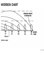
FIELD FIRING TECHNIQUES
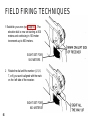
1 Establish your zero (see page 47). The
elevation dial is now set starting at 300
meters and continuing in 100 meter
increments up to 800 meters.
SIGHT SET FOR
500 METERS
2
Rotate the dial until the number (4, 5, 6,
7, or 8) you want is aligned with the mark
on the left side of the receiver.
SIGHT SET FOR
800 METERS
56
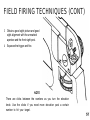
FIELD FIRING TECHNIQUES (CONT)
3
Obtain a good sight picture and good
sight alignment with the unmarked
aperture and the front sight post.
4
Squeeze the trigger and fire.
NOTE
There are clicks between the numbers as you turn the elevation
knob. Use the clicks if you need more elevation past a certain
number to hit your target.
57
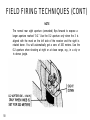
FIELD FIRING TECHNIQUES (CONT)
NOTE
The normal rear sight aperture (unmarked) flips forward to expose a
larger aperture marked “0-2.” Use the 0-2 aperture only when the 3 is
aligned with the mark on the left side of the receiver and the sight is
rotated down. You will automatically get a zero of 200 meters. Use the
0-2 aperture when shooting at night or at close range, e.g., in a city or
in dense jungle.
58
ADDITIONAL INFORMATION
CONCERNING YOUR M16A2
SIGHTS
GENERAL. Your rifle sights should be set to a combat zero of 300 meters. If you are told to
engage a target at longer range, e.g., 500 or 800 meters:
a. Rotate the elevation knob so that the desired range mark is aligned with the mark on the left
side of the receiver.
b. Aim, squeeze the trigger, and fire.
NOTE
Return the dial to 300 meters when the mission is over
C.
See conversion chart in back of manual. (pages 118-119).
59
ADDITIONAL INFORMATION
CONCERNING YOUR M16A2
SIGHTS (CONT)
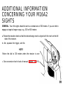
SHOOTING AT NIGHT OR AT CLOSE RANGE
a. Rotate the elevation knob down to the 300-meter mark.
b. Flip the unmarked aperture down and use the larger aperture marked “0-2.”
NOTE
The 0-2 aperture is preset for targets between 0 and 200 meters. Moving
targets at close ranges are easier to hit if you use the larger aperture.
60
USE OF SELECTOR LEVER
SAFE
Rifle will not fire. Selector lever cannot be on
SAFE unless rifle is cocked. Always place on
SAFE when loading and unloading.
SEMIAUTOMATIC
Rifle will fire one round each time the trigger is
pulled.
BURST
Rifle will fire a three-round burst each time the
trigger is pulled.*
● For information on operation of three-round burst, see page 63.
61
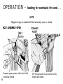
OPERATION
62
OPERATION -
three-round burst control
GENERAL.
a. Provides you three rounds per trigger pull.
b. Helps you save ammunition.
c. Gets back on target quicker than if rifle were
fired like a machine gun.
FIRING.
a.
First (or maybe last) trigger pull may not fire more than one or two rounds.
NOTE
This is not a malfunction.
b.
Quickly pull trigger again all the way to the rear and hold to get a full three-round burst. This is
called “double squeezing” the trigger. This technique is often necessary if firing is continued
after changing magazines or switching from semi to burst.
NOTE
If you release the trigger before all three rounds are fired, your next pull on the
trigger will fire only the remaining rounds from the previous burst. Once you
squeeze off a burst, keep the squeeze on until the three-round cycle is
complete.
63
OPERATION -
64
loading for semiauto fire and . .
■
m,
chambering a round
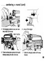
3 Push upward until magazine catch
engages and holds magazine.
4 Tap upward to make sure it’s seated right.
65
OPERATION -
loading for semiauto fire and. . .
NOTE
Magazine may be loaded with bolt assembly open or closed.
Depress upper portion of bolt catch. Bolt
should go forward.
66
TAP forward assist to ensure bolt is fully
forward and locked.
. . . chambering a round (cont)
BOLT ASSEMBLY CLOSED
Pull charging handle fully rearward.
Release the charging handle.
TAP forward assist to ensure bolt is fully
Never “ride” the charging handle. Let it go
forward and locked.
foward on its own.
NOTE
If rifle is not to be fired immediately, close ejection port cover.
67
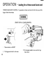
OPERATION -
loading for a three-round burst and
THREE-ROUND BURST CONTROL. To guarantee a three-round burst the first time you pull the
trigger, follow these steps:
START WITH A CLEAR WEAPON.
68
1
Place selector on BURST
2
Pull trigger and hold it to the rear.
3 Pull charging handle to rear and let it go
three times.
. . . cambering a round (cont)
69
OPERATION -
page 66
70
loading for a three-round burst and
10 Placing the selector on BURST and pulling the trigger will give you a three-round burst.
NOTE
If rifle is not to be fired immediately, close ejection port cover.
71
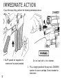
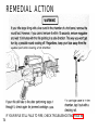
IMMEDMATE ACTION
If your rifle stops firing, perform the following immediate actions:
1 SLAP upward on magazine to
make sure it’s properly seated.
Do not load with a hot chamber.
2
72
PULL charging handle all the way back. OBSERVE
ejection of case or cartridge. Check chamber for
obstruction.
IMMEDIATE ACTION (CONT)
3 If cartridge or case is ejected or chamber is
clear, RELEASE charging handle to feed
new round. Don’t ride the charging handle
foward.
4 TAP forward assist.
5 Now FIRE. If it won’t fire, look for trouble
and apply remedial action (next page).
73
REMEDIAL ACTION
IF YOUR RIFLE STILL FAILS TO FIRE, CHECK TROUBLESHOOTING PAGE 86.
74
75
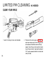
LIMITED PM CLEANING
AS NEEDED
CLEAR YOUR RIFLE
1 Look for fouling in bore and chamber.
76
2
Remove bolt carrier group (see page 12)
and clean carbon and oil from firing pin and
all surfaces of bolt/bolt carrier with dry
swabs. Clean firing pin hole and bolt carrier
key with pipe cleaner. Apply light coating of
CLP, paying special attention to slide and
cam pin area.
LIMITED PM CLEANING
AS NEEDED (CONT)
3 “Swab out” rifle from chamber to muzzle.
CAUTION: Don’t bend or flex cleaning rod,
Make sure swab goes clear through compensator.
Do not reverse direction while swab is in bore or
compensator.
4
77
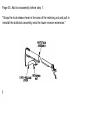
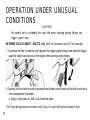
OPERATION UNDER UNUSUAL
CONDITIONS
CAUTION
Be careful not to accidently fire your rifle when inserting gloved fingers into
trigger guard area.
EXTREME COLD CLIMATE - ARCTIC: Use LAW for lubrication and CLP for cleaning.*
1 To operate the rifle in extreme cold, depress the trigger guard plunger and open the trigger
guard to obtain easy access to the trigger when wearing arctic mittens.
2 Cleaning and lubrication should be accomplished inside a warm room and the rifle should be at
room temperature if possible.
a. Apply a light coat of LAW to all functional parts.
*CLP must be kept warm in extreme cold. Carry it in your shirt pocket to keep it fluid.
78
OPERATION UNDER UNUSUAL
CONDITIONS (CONT)
b.
To Prevent the condensation of moisture and freezing, keep the weapon covered when
meting from a warm to a cold area to allow gradual coding.
c. Always attempt to keep the weapon dry.
d. Unload and hand function the weapon every 30 minutes to help prevent freezing of
functional parts.
e. Do not lay a warm weapon directly in snow or ice.
f . When moving a cold rifle into a warm place, condensation (moisture) will form in and on
your weapon. If possible, leave your weapon in a protected but cold area outside. When
the weapon is brought inside a warm place, it should be disassembled and wiped dry
several times as it reaches room temperature.
g. Keep the insides of magazines and your ammo wiped dry. Moisture will freeze and cause
malfunctions. Do not lube the ammo.
h. The use of the muzzle cap, protective magazine bag, and an overall rifle cover will help
protect your rifle. Use them whenever the tactical situation permits.
i. For extended operations in extreme cold, have armorer remove trigger guard.
79
OPERATION UNDER UNUSUAL
CONDITIONS (CONT)
HOT, WET CLIMATE - JUNGLE: Use CLP to clean and lube.
80
1
Perform normal maintenance as outlined in the PMCS table on page 44.
2
Clean and lube rifle more frequently. Inspect hidden surfaces of the bolt and carrier assembly,
upper receiver and chamber/barrel extension (locking lugs), and the lower receiver and
receiver extension assembly (buffer tube) for corrosion. Also pay close attention to the springIoaded detents on the rifle.
3
To help prevent corrosion, remove handprints with a dry wiping rag. Then lubricate lightly with
CLP.
4
Unload and check the inside of magazines frequently for corrosion and moisture. Wipe ammo
dry before reloading.
5
Use magazine bag, muzzle cap, etc. for protection when the tactical situation permits.
OPERATION UNDER UNUSUAL
CONDITIONS (CONT)
HOT, DRY CLIMATE - DESERT: Use CLP to clean and lube.
Hot, dry climates are usually areas containing blowing sand and fine dust. Deserts can be hot
during daylight hours and freezing during hours of darkness. Consequently, this harsh environment will severely tax your rifle as well as all other types of equipment. Your rifle’s continued
operation will depend on your detailed cleaning and lubricating procedures.
1
Dust and sand will get into the rifle and magazines. This will cause malfunctions. Give the
inside areas and functional parts of the rifle a thorough cleaning everyday and after every firing
mission.
2
Corrosion is less likely to form on metal parts in a dry climate; therefore, lubrication should be
applied to the internal working surfaces and functional parts only. Use normal amounts of CLP
for lubrication (always shake CLP prior to use). Unload and dry ammo and inside of magazines
daily. Do not lube magazines.
81
OPERATION UNDER UNUSUAL
CONDITIONS (CONT)
HOT, DRY CLIMATE - DESERT (CONT):
3 The use of overall rifle protection cover, muzzle cap, and spare magazine protective bags will
help protect the rifle/ammo from sand and dust. Use these items when the tactical situation
permits.
4 At all times, however, as a minimum effort to help keep out sand and dust, keep the bolt and
ejection port cover closed, a magazine installed in the rifle, and a muzzle capon the muzzle.
NOTE: Removal of the muzzle cap prior to firing is recommended. Place it
in your pocket for future use. However, it is not dangerous to fire the rifle with
the muzzle cap installed.
82
OPERATION UNDER UNUSUAL
CONDITIONS (CONT)
HEAVY RAIN AND FORDING OPERATIONS - ALL CLIMATES
1 Perform maintenance in accordance with the appropriate climate conditions.
2 Always attempt to keep rifle dry.
3
Use rifle cover, muzzle cap, and protective bags to protect rifle, ammo, and
magazines.
4
Always drain any water from barrel prior to firing. Dry the bore with a swab and
cleaning rod if it is wet.
NUCLEAR, BIOLOGICAL AND CHEMICAL (NBC). General procedures can be found in
FM 3437, FM 21-40 and TM 3-220.
83
OPERATION UNDER UNUSUAL
CONDITIONS (CONT)
AFTER FORDING
DO NOT FIRE RIFLE IF WATER IS PRESENT IN BARREL.
AFTER YOU REMOVE THE CAP:
1 REMOVE MUZZLE CAP.
84
2 POINT THE MUZZLE DOWN AND SHAKE
VIGOROUSLY.
OPERATION UNDER UNUSUAL
CONDITIONS (CONT)
AFTER FORDING (CONT)
NOTE: For additional information. see FM 23-9
85
86
TROUBLESHOOTIN (CONT)
PROBLEM
CHECK FOR
WHAT TO DO
BOLT WON’T
UNLOCK
Dirty or burred bolt.
See your NCO or your unit ARMORER.
WONT EXTRACT
Broken extractor spring.
Dirty or corroded ammo.
See your ARMORER.
Remove.
Push out stuck round with cleaning rod.
Carbon in chamber.
Fouling or carbon in
extractor recess or lip.
Clean chamber.
Clean.
87
TROUBLESHOOTING (CONT)
PROBLEM
CHECK FOR
WHAT TO DO
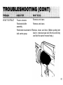
WON'T FEED
Dirty or corroded ammo.
Dirty magazine.
Defective magazine.
Too many rounds in
magazine.
Action of buffer assembly
is restricted,
Clean.
Clean.
Replace.
Take out excess.
Magazine not fully
seated.
PRESS BUTTON
ON RIGHT SIDE
88
Take out buffer and spring and clean.
Adjust magazine catch.
TROUBLESHOOTING (CONT)
PROBLEM
CHECK FOR
WHAT TO DO
Turn catch clockwise to tighten and
counterclockwise to loosen.
WON'T FEED
(CONT)
TURN CATCH ON
LEFT SIDE
DOUBLE FEED
Defective magazine.
Replace.
89
TROUBLESHOOTING (CONT)
CHECK FOR
WON'T CHAMBER
Dirty or corroded ammo. Clean.
Replace.
Damaged ammo.
Carbon in chamber or on
gas tube.
Dirt, corrosion, or carbon
buildup in barrel locking
lugs.
90
WHAT TO DO
PROBLEM
Clean lugs
WON’T EXTRACT
Remove and clean.
Frozen extractor.
Remove and clean.
Restricted buffer
assembly.
Restricted movement of Remove, clean, and lube. (Before putting bolt
back in, make sure gas tube fits into carrier key
bolt carrier group.
and that the carrier moves freely.)
91
TROUBLESHOOTlNG (CONT)
PROBLEM
SHORT RECOIL
CHECK FOR
WHAT TO DO
Gaps in bolt rings (not
staggered).
Stagger ring gaps.
Carbon or dirt in carrier Clean.
key or on outside of gas
tube.
92
TROUBLESHOOTING (CONT)
PROBLEM
CHECK FOR
Q-Tip/pipe cleaner
stuck inside carrier
key.
BOLT FAILS TO
LOCK AFTER LAST
ROUND
Dirty or corroded bolt
latch.
SELECTOR LEVER
Faulty magazine.
BINDS
Needs oil.
WHAT TO DO
Return rifle to armorer.
Clean.
Replace.
Lubricate with CLP.
Dirt or sand under trigger. Clean.
93
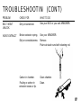
TROUBLESHOOTING (CONT)
WHAT TO DO
PROBLEM
CHECK FOR
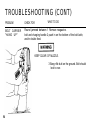
BOLT CARRIER
"HANG UP"
Round jammed between 1 Remove magazine.
bolt and charging handle 2 push in on the bottom of the bolt latch,
and/or double feed.
KEEP CLEAR OF MUZZLE.
3 Bang rifle butt on the ground. Bolt should
lock to rear.
94
TROUBLESHOOTING (CONT)
PROBLEM
CHECK FOR
WHAT TO DO
CAUTION
After round is removed, bolt is under tension.
NOTE
If this procedure fails, use a section of cleaning rod to push bolt fully to rear through
ejection port.
95
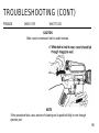
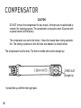
COMPENSATOR
CAUTION
DO NOT remove the compensator for any reason. Armorers are not authorized to
remove it for cleaning puposes. The compensator is torqued to about 20 pounds with
a special wrench at the factory.
The compensator was set at the factory. It leeps the muzzle down during automatic
fire. The setting is precise so that the slots are indexed, as shown below.
The compensator has five slots. The third or middle slot must be straight up.
THIRD SLOT
Straight Up
It should line up with the front sight post.
96
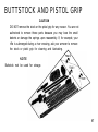
BUTTSTOCK AND PISTOL GRIP
CAUTION
DO NOT remove the stock or the pistol grip for any reason. You are not
authorized to remove these parts because you may lose the small
detents or damage the springs upon reassembly. If, for example, your
rifle is submerged during a river crossing, ask your armorer to remove
the stock or pistol grip for cleaning and lubricating.
NOTE
Buttstock mat be used for storage.
97
LOADING MAGAZINE
The magazine may be loaded quickly using
ten-round stripper clips and the magazine filler
found in each bandoleer.
TEN-ROUND
STRIPPER CLIP
1 With the magazine filler in place, place a
ten-round stripper clip in position. Using
thumb pressure on the rear of the top cartridge, press down firmly until all ten rounds
are below the feed lips of the magazine.
MAGAZINE FILLER
(FOUND IN END
POCKET OF BANDOLEER)
98
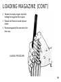
LOADING MAGAZINE (CONT)
2
Remove the empty stripper clip while
holding the magazine filler in place.
3
Repeat until three ten-round clips are
Ioaded.
4
Remove magazine filler and retain it for
future use.
LOADING PROCEDURE
99
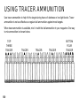
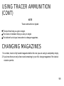
USING TRACER AMMUNITION
Use tracer ammunition to help hit the target during hours of darkness or low light levels. Tracer
ammunition is not as effective as regular ball ammunition against most targets.
When tracer ammunition is available, mix it in with the ball ammunition in your magazine. One way
to mix ammunition is shown below.
TOP
THREE
TRACER
100
TRACER
TRACER
TRACER
BOTTOM
FOUR
TRACER
USING TRACER AMMUNITION
(CONT)
NOTE
Tracer ammunition is tipped
The top three help you get on target.
The traces in between help you stay on target.
The bottom four let you know when to change magazines.
CHANGING MAGAZINES
1 In combat, insert a fully loaded magazine before the one you are using is completely empty.
2 If you know there are only a few rounds remaining in your rifle, change magazines if the tactical
situation permits.
101
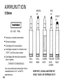
AMMUNITION
GREEN
TIP
5.56mm
RED
TIP
VIOLET
TIP
DO NOT FIRE...
Seriously corroded ammunition.
Dented cartridges.
Cartridges with loose bullets.
Cartridges exposed to extreme heat
(135 F°) until they have cooled.
Cartridges with the bullet pushed in
(short rounds).
...TURN IN TO RANGE NCO.
Use only authorized ammunition that is
manufactured to U.S. or NATO
specifications.
102
BALL,
M193
BALL,
M855
DUMMY,
M199
TRACER
M196
& M856
KEEP DRY, CLEAN, AND FREE OF
CRUD; YOUR LIFE DEPENDS ON IT!
BLANK,
M200
REFERENCE PUBLICATIONS
FMFM 1-3A
Field Firing Techniques
FMFM 6-5
Marine Rifle Squad
SI-1300-15/1
Ammo Data Cards, Marine Corps Ammo
SI-1300-15/2B
Procedure for Requesting Disposition for Class V(W) Materiel
TM 4700-15/1
Record Reporting Procedures
TM 05538C/23/2
Organizational and Intermediate Maintenance, M16A2 Rifle
FM 23-9
M16A1 Rifle and Rifle Marksmanship
FM 3437
Nuclear, Biological and Chemical Reconnaissance
and Decontamination Operations
FM 21-11
First Aid for Soldiers
FM 21-40
NBC (Nuclear, Biological and Chemical Defense)
TM 3-220
Chemical, Biological and Radiological (CBR)
Decontamination
Army Use Only
DA PAM 738-750
The Army Maintenance Management System (TAMMS)
103
MARINE CORPS USE ONLY
COMPONENTS LIST FOR RIFLE,
5.56MM, M16A2
PREFACE
SCOPE
1. This publication lists all components and accessories for collection-type supply items, such as
major combinations, systems, groups, outfits, kits, sets or assortments. The components to be
issued with the end item are identified under the heading of “SUPPLY SYSTEM
RESPONSIBILITY" and when required, under the heading “COLLATERAL MATERIEL.” End
items requiring collateral materiel are governed by whether the end item is initial or replacement
issue. The Marine Corps Logistics Support Base, Atlantic will direct whether the initial issue of the
end item is with a collateral materiel set or replacement issue without collateral materiel. The
components to be issued will consist of the quantity of items annotated in the “Quantity Used in
Unit” column. The “USING UNIT RESPONSIBILITY” heading will reflect those items that are to be
requisitioned separately through the supply system when applicable.
104
MARINE CORPS USE ONLY
COMPONENTS LIST FOR RIFLE,
5.56MM, M16A2 (CONT)
LIST OF COMPONENTS
2. This listing comprises the major portion of this publication. The data, arranged in columnar
form, presents the information needed to identify the item and determine its type of issue.
3. Item Number (Column 1). This column specifies a number assignment for each item as it
appears in the list. Numbers are assigned in sequence and are for reference purposes only.
4. Stock Number (Column 2). This column furnishes the National Stock Number (NSN)
and to the item.
5. Reference Designation/Figure-Key (Column 3). This column indicates circuit-symbol number
designators or figure and index numbers to refer an item to a circuit diagram or illustration.
6. Model (Column4). This column indicates in alphabetical code the specific application of
components, or assemblies when more than one model of the end item is contained in this
publication.
7. Item Identification (Column 5). This column provides the item name and description Iisted
under the heading of either “SUPPLY SYSTEM RESPONSIBILITY,” “COLLATERAL
MATERIEL" or "USING UNIT RESPONSIBILITY." (See paragraphs 10, 11, and 12.)
105
MARINE CORPS USE ONLY
COMPONENTS LIST FOR RIFLE,
5.56MM, M16A2 (CONT)
8. Unit of Measure (Column 6). This column gives the measurement standard of each item. It
may or may not be the same as the unit of issue. For example, the unit of issue of a certain wire is
coil but only 4 feet are required for the end item. Therefore, the unit of measure shown will not be
used for requisitioning purposes. For the proper unit of issue and other required management
data, refer to the applicable Management Data List (ML) when requisitioning.
9. Quantity Used in Unit (Column 7). This column lists the total quantity of an item according to
the unit of measure, required for full functional operation of the end item.
SUPPLY SUPPORT CATEGORIES
10. Supply System Responsibility. All or a portion of the items in this category, as appropriate for
the type of issue, will be furnished by the supply system. Any item requiring replacement, while the
end item is outside the stores distribution system, is the responsibility of the holding organization or
using unit.
11. Collateral Materiel. All of the items in this category will be furnished with the end item when
the end item is being shipped as initial issue. The 9999-00-000-0000 NSN shown under the
heading of “COLLATERAL MATERIEL” is for control within the distribution system only, and is not
authorized for requisitioning purposes.
106
MARINE CORPS USE ONLY
COMPONENTS LIST FOR RIFLE,
5.56MM, M16A2 (CONT)
12. Using Unit Resposibility. Items in this category will not be issued with the end item. They
must be requisitioned through the supply system. The end item will be complete only when the total
quantity of items shown in the "Quantity Used in Unit" column as well as those items listed under
the heading “SUPPLY SYSTEM RESPONSIBILITY” and “COLLATERAL MATERIEL” are on
hand.
5TH ECHELON REHABILITATION PROGRAM
13. Major items returned under this program will be evacuated under the provision(s) of the
applicable Marine Corps Order(s) with the items listed under Supply System Responsibility.
Repair, rebuild end replacement under a 5th Echelon rehabilitation program will be limited to these
items only. Those items under the heading “COLLATERAL MATERIEL” shall be held by using
organizations for application to the replacement end items.
CHANGES
14. Changes to this publication will be issued as required.
107
FOR MARINE CORPS USE ONLY
COMPONENTS LIST FOR RIFLE,
5.56MM, M16A2 (CONT)
REQUEST FOR ADDITONAL COPIES
15. Additional copies of this publication may be requisitioned from the Commanding General,
Marine Corps Logistics Base, (Code 876), Albany, Georgia 31704-5000.
ERRORS AND RECOMMENDATIONS
16. Errors in this publication or recommendations for its improvement should be submitted by
using NAVMC 10772 “Report of Discrepancy in Supply Publications” form provided each Command for this purpose. If this form is not adequate to cover a particular situation or recommendation, a letter should be directed to Commandant of the Marine Corps, Code LMA-1, Headquarters
U.S. Marine Corps, Washington, D.C., 20380. Army users submit DA Form 2028
(Recommend Changes to Publications and Blank Forms) direct to Commander, US
Army Armament, Munitions and Chemical Command, ATTN: AMSMC-MAS, Rock
Island, IL 61299-6000.
108
FOR MARINE CORPS USE ONLY
COMPONENTS LIST FOR RIFLE,
5.56MM, M1 6A2 (CONT)
MISCELLANEOUS
17. For full information concerning the Marine Corps Stocklist publications system, including its
purpose and use and the principles employed in its compilation, see Marine Corps Stocklist,
SL-1-1, Introduction to Marine Corps Stocklist Publications; for indexes thereof, see Marine Corps
Stocklist micropublications SL-1-2, Index of Authorized Publications for Equipment Support, and
SL-1-3, Index of Publications Authorized and Stocked by the Marine Corps (PASMC).
SPECIAL NOTES
18. The Rifle, 5.56mm, M16A2, will be reported on Unit Property Control Records under NSN
1005-01-128-9936. Rifle, 5.56mm, M16A2, NSN 1005-01-128-9936 includes 1 ea magazine,
NSN 1005-00-921-5004.
19. Maintenance Forms and Records. Marine Corps users maintain forms and
records as prescribed by TM 4700-15/1. Department of the Army forms and records
will be those prescribed by DA PAM 738-750.
109
110
MARINE CORPS USE ONLY
COLLATERAL MATERIEL (CONT)
NSN 9999-01-189-3261
7
No.
STOCK
NUMBER
REF
DESIG
FIG
KEY
1
1
2
2
3
3
4
4
6 1005-01-113-0321
IN
UNIT
BRUSH, CLEANING, SMALL ARMS: Bore;
Rock Island Arsenal, 11686340
BRUSH, CLEANING, SMALL ARMS:
Chamber; Rock Island Arsenal, 8432358
BRUSH, CLEANING: Tooth; Rock island
Arsenal, S448462
CASE, SMALL ARMS ACCESSORY: Rock
Island Arsenal, 8448751
EA
1
EA
1
EA
1
EA
1
HANDLE ASSEMBLY: Rock Island Arsenal,
8436776
I I
1
EA
111
MARINE CORPS USE ONLY
COLLATERAL MATERIEL (CONT)
112
MARINE CORPS USE ONLY
COLLATERAL MATERIEL (CONT)
3
REF
DESIG
FIG
KEY
5
ITEM IDENTIFICATION
7
7
8
9
8
9
MAGAZINE CARTRIDGE: 30 round; Rock
Island Arsenal, 8448670
ROD SECTION: Rock Island Arsenal, 8436775
SMALL ARMS SLING: Rock Island Arsenal,
10
10/
No.
NUMBER
SWAB HOLDER SECTION: Rock Island
Arsenal, 11686327
UNIT
OF
MEAS
QTY
USED
EA
6
EA
EA
3
1
EA
1
IN
UNIT
113
USING UNIT RESPONSIBILITY
NOTE
Using units should refer to the SL-1-2 and requisition the required Duplication to
support the item identified by the ID number shown on the cover manual.
1
ITEM
NO.
114
STOCK
NUMBER
3
REF
DESIG
FIG
KEY
5
ITEM IDENTIFICATION
6
UNIT
OF
MEAS
QTY
USED
IN
UNIT
11
1005-00-193-8306
BAG, PROTECTIVE MAGAZINE: Rock Island
Arsenal 8448464
EA
12
1005-00-073-9238
BAYONET-KNIFE: Rock Island Arsenal, 11010077
EA
1
13
1005-00-118-6192
BLANK FIRING ATTACHMENT: Rock Island
Arsenal, 12002900
EA
A/R
14
1005-00-242-5687
BOTTLE ASSEMBLY:Rock Island Arsenal, 8448444
(1 oz bottle for LAW)
EA
A/R
15
5340-00-880-7666
CAR PROTECTIVE, DUST: Rock Island
Arsenal, 8445067
EA
A/R
A15
9150-01-102.1473
CLEANER, LUBRICANT AND PRESERVATIVE:
Military Specifications Promulgated by Standard
ization Division Directorate of Logistic Services
DSA, MIL-L-63460 (1/2 oz bottle)
A/R
A/R
USING UNIT RESPONSIBILITY (CONT)
1
ITEM
NO.
STOCK
NUMBER
16
9920-00-292-9946
17
1005-00-609-2190
16
1005-00-406-1570
19
9150-00-292-9689
20
1005-00-233-9031
21
7920-00-205-1711
22
1095-00-223-7164
3
REF
DESIG
FIG
KEY
5
ITEM IDENTIFICATION
6
UNIT
OF
MEAS
CLEANER, TOBACCO PIPE: American
Tobacco Company American Brands Inc
DILLSPIPECLEANER (36 per pkg)
COVER, PROTECTIVE, RIFLE: Rock Island
Arsenal, 8448213
KIT, ADAPTER, TOP SLING: Rock Island
Arsenal, 8448471
LUBRICATING OIL, ARTIC WEAPONS
(LAW): Military Specifications Promulgated
by Standardization Division Directorate of
Logistic Services DSA, MIL-L-14107 (1 quart
can)
PLATE, LOCKING: (for fire control use) Rock
Island Arsenal, 8448876
RAG, WIPING: Federal Commercial Item
Description executed by General Services
Administration, A-A-531 (50 lb ball)
SCABBARD, BAYONET KNIFE M8A1 or M10:
Rock Island Arsenal, 8448476
EA
A/R
EA
A/R
EA
A / R
EA
A / R
EA
A / R
LB
A / R
EA
1
115
MARINE CORPS USE ONLY
USING UNIT RESPONSIBILITY (CONT)
1
TEM
NO.
2
STOCK
NUMBER
23
1005-00-912-4248
24
6920-01-152-2891
116
3
REF
DESIG
FIG
KEY
4
M
O
D
E
5
ITEM IDENTIFICATION
SWAB, SMALL ARMS: Rock Island Arsenal,
11686408 (1000 per pkg)
TARGET, ZEROING: Rock Island Arsenal,
9357935 (500 sheet ream)
6
UNIT
OF
MEAS
QTY
USED
IN
UNIT
MX
A/R
EA
A/R
(ARMY USE ONLY)
COMPONENTS OF END ITRM AND BASIC ISSUE
ITEMS LISTS
Section I.
INTRODUCTION
1. SCOPE . This section lists components of end item and basic issue items for the rifle
to help you inventory items required for safe and efficient operation.
2. GENERAL. The Components of End Item and Basic Issue Items Lists are divided
into the following sections:
a. Section II. Components of End Item. This listing is for informational purposes
only, and is not authority to requisition replacements. These items are part of the end
item, but are removed and separately packaged for transportion or shipment. As part of
the end item, these items must be with the end item whenever it is issued or transferred
between property accounts. Illustrations are furnished to assist you in identifying the
items.
b. Section III. Basic Issue Items. These are the minimum essential items required to
place the rifle in operation, to operate it, and to perform emergency repairs. Although
shipped separately packaged, BII must be with the rifle during operation and whenever it is
transferred between property accounts. The illustrations will assist you with hard-toidentify items. This manual is your authority to request/requisition replacement BII,
based on TOE/MTOE authorization of the end item.
117
(ARMY USE ONLY)
3. EXPLANATION OF COLUMNS.
tabular listings :
The following provides an explanation of columns found in the
a. Column (1) - Illustration Number (Illus Number). This column indicates the number
of the illustration in which the item is shown.
b. Column (2) - National Stock Number. Indicates the National Stock Number assigned to
the item and will be used for requisitioning purposes.
c . Column (3) - Description. Indicates the Federal item name and, if required, a minimum description to identify and locate the item. The last line for each item indicates the
FSCM (in parentheses) followed by the part number.
Indicates the measure used in performing tbe
d. Column (4) - Unit of Measure (U/M)
actual Opera tion/maintenance function. This measure is expressed hy a two-character alphabetical abbreviation (e.g., ea, in.,pr).
e. Column (5) - Quantity required (Qty rqr). Indicates the quantity of tbe item authorized to be used with/on the equipment.
118
(ARMY USE ONLY)
Section II.
cOMPONENTS OF END ITEM (See illustration on page 112).
(4)
U/M
(5)
Qty
rqr
MAGAZINE, CARTRIDGE:
30 round
(19204) 8448670
EA
1
SLING, SMALL ARMS
(19204) 11833432
EA
1
(2)
National Stock
Number
(3)
Description
FSCM and Part Number
1
1005-00-921-5004
2
1005-01-083-8113
(1)
Illus
Number
Usable
On Code
119
(ARMY USE ONLY)
Section III.
(1)
Illus
Number
1
120
BASIC ISSUE ITEMS
(2)
National Stock
Number
(3)
Description
FSCM and Part Number
TM 05538C-10/1A/
TM 9-1005-319-10
Usable
On Code
(4)
U/M
(5)
Qty
rqr
EA
1
(ARMY USE ONLY )
ADDITIONAL AUTHORIZATION LIST (AAL)
Section I .
INTRODUCTION
1. SCOPE. This section lists additional items you are authorized for the support of the
rifle.
2. GENERAL. This list identifies items that do not have to accompany the rifle and that
do not have to be turned in with it. These items are all authorized to you by CTA, MTOE ,
TDA, or JTA.
3. EXPLANATION OF LISTING. National stock numbers , descriptions , and quantities are
provided to help you identify and request the additional items you require to support
this equipment. The items are listed in alphabetical sequence by item name under the
type document (i.e. , CTA, MTOE, TDA, or JTA) which authorizes the item(s) to you.
121
Section II .
(ARMY USE ONLY)
ADDITIONAL AUTHORIZATION LIST (AAL)
(1)
NATIONAL
STOCK
NUMBER
(2)
DESCRIPTION
FSCM AND PART NUMBER
CTA AUTHORIZED ITEMS
USABLE
ON CODE
(3)
( 4 )
U/M
QTY
AUTH
1005-00-193-8306
BAG, PROTECTIVE: for 30 round
magazine (500 per box)
required 1 per magazine
(19204) 8448464
EA
1
1005-00-118-6192
BLANK FIRING ATTACHMENT, M15A2 ,
(For Training Only)
(19204) 12002900
EA
1
1005-00-242-5687
BOTTLE ASSEMBLY CYLINDRICAL
(19204) 8448444
EA
1
122
Section II.
(ARMY USE ONLY)
ADDITIONAL AUTHORIZATION LIST (AAL) (CONT)
(1)
NATIONAL
STOCK
NUMBER
(2)
DESCRIPTION
FSCM AND PART NUMBER
USABLE
ON CODE
(3)
(4)
U/M
QTY
AUTH
1005-00-903-1296
BRUSH, CLEANING, SMALL ARMS : bore
{19204) 11686340
EA
1
1005-00-999-1435
BRUSH , CLEANING, SMALL ARMS : chamber
(19204) 8432353
EA
1
1005-00-494-6602
BRUSH , CLEANING , SMALL ARMS : tooth
(19204) 8448462
EA
1
5340-00-880-7666
CAP
EA
1
EA
1
,
PROTECTIVE,
DUST
(19204) 8445067
1005-00-403-5804
CASE , SMALL ARMS : for rifles
with buttstock stowage
(19204) 8448751
123
(ARMY USE ONLY)
Section II. ADDITIONAL AUTHORIZATION LIST (AAL) (CONT)
{1)
NATIONAL
STOCK
NUMBER
(2)
DESCRIPTION
FSCM AND PART NUNEER
USA BLE
ON CODE
(3)
(4)
U/M
QTY
AUTH
1005-01-113-0321
HANDLE SECTION, CLEANING ROD ,
SNALL ARNS
(19204) 8436776
EA
1
1005-00-921–5004
NAGAZINE, CARTRIDGE : 30 round
(19204) 8448670
EA
1
1005-00-233-9031
PLATE, LOCKING : for riot control use,
prevents selector from automatic fire
(refer to organization maintenance
for installation and instructions on use
(19204) 8448676
EA
1
1005-00-050-6357
ROD SECTION, CLEANING ROD , SMALL ARNS
(19204) 8436775
EA
3
124
Section
II.
~DITIONW
(1)
NATIONAL
sm~
RUMER
1005-00-937-2250
(ARMY USE ONLY)
AUTHORIZATION LIST (W) (CONT)
(2)
DESCRIPTION
FSCM AND PART NUMBER
SWAB HOLDER SECTION , CLEANING
ROD , WALL ARMS
(19204) 11686327
(3)
USABLE
ON CODE
U/M
EA
(4)
QTY
AUTH
1
125
Section
II.
ADDITIONAL
(1)
NATIoNAL
STOCK
NUMBER
(ARMY usE ONLY)
AUTHORIZATION LIST (AAL) (CONT)
(2)
DESCRIPTION
FSCM AND PART NUMBER
USABLE
ON CODE
(3)
(4)
Ul)i
QTY
AUTH
EA
1
EA
1
MTOE AUTliORIZED ITEMS
1005-00-017-9701
BAYONET
(19204)
1005-00-406-1570
TOP SLING ADAPTER
(19204) 6448471
126
- KNIFE M7 W/SCABBARD
8427025
KIT
(ARMY
USE
ONLY)
EXPENDABLE/DURABLE SUPPLIES AND
NATERIALS LIST (EDSML)
Section I . INTRODUCTION
1. SCOPE. This section lists expendable supplies and materials you will need to
operate and maintain the M16A2 rifle. This listing is for informational purposes
only and is not authority to requisition the listed items. These items are authorized to you by CTA 50-970, Expendable/Durable Items (Except Medical, Class V, Repair
Parts , and Heraldic Items) , or CTA 8-100, Army Medical Department Expendable/Durable
Items.
2. EXPLANATION OF COLUMNS.
a. Column (1) - Item Number. This number is assigned to the entry in the Iisting
and is referenced in the narrative instructions to identify the material (e.g., “Use
protective cover (item 3)"
127
(ARMy usE ONLY)
2. EXPLANATION
OF COLUMNS
b. Column (2) - Level.
requires the listed item.
(CONT)
This column identifies
the lowest level of maintenance
that
C - Operator/Crew
c. Column
to the item;
(3) - National Stock Number. This is the National
use it to request or requisition the item.
stock number assigned
d. Column (4) - Description. Indicates the Federal item name and, if required, a
description to identify the item.
The last line for each item indicates the Federal
Supply Code for Manufacturer (FSCN) in parentheses followed by the part number.
e. Column (5) - Unit of Measure (U/M) . Indicates the measure used in performing
the actual maintenance function. This measure is expressed by a two-character alphabetical abbreviation (e.g. , ea, in. , pr) . If the unit of measure differs from the
unit of issue , requisition the lowest unit of issue that will satisfy your requirements.
128
(ARMY USE ONLY)
Section II .
(1)
EXPENDABLE SUPPLIES AND MATERIALS LIST (ESML)
(2)
(3)
NATIONAL
STOCK
NUMBER
(4)
(5)
ITEM
NO.
LEVEL
1
c
9150-01-102-1473
CLEANER, LUBRICANT AND
PRESERVATIVE: l-oz bottle
(81349) MIL-L-63460
Oz
2
c
9920-00-292-9946
CLEANER, TOBACCO PIPE :
cotton tuft, wire core
(32 per pk)
( 89855) DILLSPIPECLEANER
EA
3
c
1005-00-809-2190
COVER, PROTECTIVE
(19204) 8448213
EA
DESCRIPTION
U/M
129
(ARMY USE ONLY)
Section II .
EXPENDABLE SUPPLIES AND MATERIALS LIST (ESML) (CONT)
(3)
NATIONAL
STOCK
NUMBER
(1)
(2)
ITEM
NO.
LEvEL
4
c
9150-00-292-9689
LUBRICATING OIL, ARTIC
WEAPONS (LAW) MIL-L-14107
( 1 quart can)
EA
5
c
7920-00-205-1711
RAG, WIPING : 50 lb bdl
(58536) A-A-531
LB
6
c
1005-00-912-4248
SWAB , SMALL ARMS CLEANING:
cotton, 1 pkg (1000 per
package)
(19204) 11686408
EA
130/(131 blank)
(4)
DESCRIPTION
(5)
U/M
TRAJECTORIES OF AIMED RIFLE FIRE WITH CORRECT
ELEVATION SET ON REAR SIGHT ELEVATION KNOB
METRIC CO
RANGE
Point of aim at each target, at all ranges, is “center of mass” or in center of chest. Point of impact is
also center of mass. Note that fire on target at 300 meters is also effective on 400 meter target. At
600 meters, fire does not exceed the height of a man at any point along its trajectory.
132
NVERSION CHART
1
3
3
TM 05538C-10/1/A
TM9-1005-319-10
THIS PUBLICATION IS REQUIRED FOR OFFICIAL USE OR FOR ADMINISTRATIVE OR OPERATIONAL PURPOSES. DISTRIBUTION IS LIMITED TO U.S.
GOVERNMENT AGENCIES ONLY. OTHER REQUESTS FOR THIS DOCUMENT MUST
COMMANDANT OF THEE MARINE COPRPS (HQSP-2),
BE REFERRED TO:
WASHINGTON, C.C.
20380-0001.