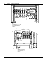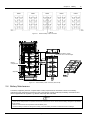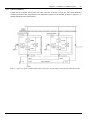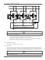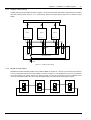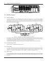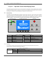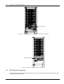
1
Liebert NX NXr 8VHU0DQXDO 30 to 200 kVA UPS cubicles parallelable to 800kVA Modular NXr UPS 30kVA ~ 200kVA (parallelable to 800kVA) User Manual Version Revision date BOM V1.2 ENPAu 2011 0401 (ENPAu 2011 1108) 31012244 Emerson Network Power provides customers with technical support. Users may contact the nearest Emerson local sales office or service center. Copyright © 2010 by Emerson Network Power Co., Ltd. All rights reserved. The contents in this document are subject to change without notice. Emerson Network Power Co., Ltd. Address: No.1 Kefa Rd., Science & Industry Park, Nanshan District 518057, Shenzhen China Homepage: www.emersonnetworkpower.com.cn E-mail: [email protected] Safety Precaution This manual covers the installation and use of Emerson NXr UPS. Please read this manual before installation. The NXr UPS must be commissioned and maintained by the engineers designated by the manufacturer or its agent. Failure to observe this could result in personnel safety risk, equipment malfunction and invalidation of warranty. The NXr UPS is only used for commercial or industrial purpose and cannot be used as life support equipment. This is a C2 type UPS product. In a domestic environment, this product may cause radio frequency interference, in which case, the user may be required to take additional measures. Conformity and standards This product complies with CE 2006/95/EC (low voltage safety) and 2004/108/EC (EMC), EMC standards of Australia and New Zealand (C-Tick), and the following UPS product standards: * IEC62040-1-1-General and safety requirements for use in operator access area * IEC/EN62040-2 EMC requirements CLASS C2 * IEC62040-3 Performance requirements and test methods For more details, refer toChapter 8 Product Specifications. Continued compliance requires installation in accordance with these instructions and the use of manufacturer approved accessories only. Warning: high earth leakage current Earth connection is critical before connecting the input supply (including both mains supply and battery). Earth leakage current exceeds 3.5mA and is less than 1000 mA. Transient and steady state earth leakage currents, which may occur when the equipment is started, should be taken into account in the selection of instantaneous residual current circuit breakers (RCCBs or residual current detector (RCD devices. Note also that the earth leakage currents of the load will be carried by the RCCBs or RCDs. The equipment must be earthed in accordance with the local electrical authority codes of practices. Warning: backfeeding protection This UPS is fitted with a voltage-free contact closure signal for use with an external automatic disconnect device (supplied by others), to protect against backfeeding voltage into the incoming termninal through the static bypass circuit. If this signal is not used by the installer, a label must be added at the external incoming bypass supply disconnect device to warn service personnel that the circuit is connected to a UPS. The text has the following meaning or is equivalent to: Isolate the UPS before working on this circuit. User serviceable components All the equipment maintenance and servicing procedures involving internal access need special tools and should be carried out only by trained personnel. The components that can only be accessed by opening the protective cover with tools cannot be maintained by the user. This UPS fully complies with the general and safety requirements for use in operator access area. Dangerous voltages are present within the UPS and battery enclosure but out of reach of non-service personnel. Contact of these voltages is minimized, because live parts are housed behind protective covers that require a tool for their removal. No risk exists if you operate the equipment in the normal manner, following the recommended operating procedures in this manual. Battery voltage higher than 400Vdc All the battery physical maintenance and servicing procedures need special tools or keys and should be carried out only by trained personnel. Take special care when working with the batteries associated with this UPS. When the batteries are connected together, the battery terminal voltage exceeds 400vdc and is potentially leathal. Battery manufacturers supply details of the necessary precautions to be observed in working on, or in the vicinity of, a large bank of battery cells. These precautions should be followed implicitly at all times. Particular attention should be paid to the recommendations concerning local environmental conditions and the provision of protective clothing, first aid and fire-fighting facilities. Contents Chapter 1 Installation Of single UPS cubicle ....................................................................................................................... 1 1.1 Brief Introduction ................................................................................................................................................... 1 1.2 Initial Check .......................................................................................................................................................... 1 1.3 Location Selection................................................................................................................................................. 2 1.3.1 UPS Room................................................................................................................................................. 2 1.3.2 External Battery Room............................................................................................................................... 2 1.3.3 Storage ...................................................................................................................................................... 2 1.4 Positioning ............................................................................................................................................................ 3 1.4.1 System Cabinet ......................................................................................................................................... 3 1.4.2 Moving Cabinet .......................................................................................................................................... 3 1.4.3 Clearance .................................................................................................................................................. 3 1.4.4 Front Access.............................................................................................................................................. 3 1.4.5 Final Positioning And Fixing ...................................................................................................................... 3 1.4.6 Cable Entry ................................................................................................................................................ 5 1.5 External protective device ..................................................................................................................................... 5 1.5.1 Rectifier And Bypass Input ........................................................................................................................ 6 1.5.2 External Battery Circuit Breaker ................................................................................................................ 6 1.5.3 UPS Output ............................................................................................................................................... 6 1.6 Power Cables ....................................................................................................................................................... 6 1.6.1 Maximum Steady State AC And DC Currents Maximum steady state AC and DC currents ................... 6 1.6.2 Distance From Floor To Connection Point On The Equipment .................................................................. 7 1.6.3 Cable Connection ...................................................................................................................................... 7 1.7 Control Cables And Communication ................................................................................................................... 12 1.7.1 Input Dry Contact Port: Battery Environment (ventilation), Ground fault, Temperature ........................... 12 1.7.2 Battery Circuit-Breaker (BCB) Port .......................................................................................................... 13 1.7.3 Maintenance Switch And Output Switch State Port ................................................................................. 13 1.7.4 Backfeed protection Output Dry Contact Port .......................................................................................... 14 1.7.5 Remote Emergency Power Off (REPO) Input Port .................................................................................. 14 1.7.6 Relay and Network Interface Card ports, Service ports, .......................................................................... 15 Chapter 2 Battery .............................................................................................................................................................. 16 2.1 Brief Introduction ................................................................................................................................................. 16 2.2 Safety.................................................................................................................................................................. 17 2.3 Battery Power Cable ........................................................................................................................................... 18 2.3.1 Overview.................................................................................................................................................. 18 2.3.2 Battery Installation ................................................................................................................................... 18 2.3.3 Battery Connection .................................................................................................................................. 18 2.4 Battery Maintenance ........................................................................................................................................... 19 2.5 Battery Recycling ................................................................................................................................................ 20 2.6 Connection Of External Battery Circuit-Breaker (BCB ........................................................................................ 20 Chapter 3 Installation Of Multiple UPS cubicles ................................................................................................................ 22 3.1 Overview ............................................................................................................................................................. 22 3.2 1 + N Parallel System ......................................................................................................................................... 22 3.2.1 Cabinet Installation .................................................................................................................................. 23 3.2.2 External protective device........................................................................................................................ 24 3.2.3 Power Cable ............................................................................................................................................ 24 3.2.4 Auxiliary Control Wiring ........................................................................................................................... 25 3.2.5 Parallel Control Cables ............................................................................................................................ 25 3.3 Dual Bus System ................................................................................................................................................ 26 3.3.1 Cabinet Installation .................................................................................................................................. 26 3.3.2 External protective device........................................................................................................................ 26 3.3.3 Power Cable ............................................................................................................................................ 26 3.3.4 Control Cable ........................................................................................................................................... 26 Chapter 4 System Description........................................................................................................................................... 28 4.1 Brief Introduction ................................................................................................................................................. 28 4.1.1 Operating Theory ..................................................................................................................................... 28 4.1.2 Static (bypass) Transfer Switch ............................................................................................................... 28 4.2 1 + N Parallel System ......................................................................................................................................... 29 4.2.1 Parallel System Features......................................................................................................................... 29 4.2.2 Requirements For Paralleling Of UPS Modules ....................................................................................... 29 4.3 Operation Mode .................................................................................................................................................. 29 4.3.1 Normal Mode ........................................................................................................................................... 30 4.3.2 Battery Mode ........................................................................................................................................... 30 4.3.3 Automatic Restart Mode .......................................................................................................................... 30 4.3.4 Bypass Mode ........................................................................................................................................... 30 4.3.5 Maintenance Mode (Manual Bypass) ...................................................................................................... 30 4.3.6 Parallel Redundancy Mode (System Expansion) ..................................................................................... 30 4.4 Battery Management (Set During Commissioning) ............................................................................................. 30 4.4.1 Normal Function ...................................................................................................................................... 30 4.4.2 Advanced Function .................................................................................................................................. 31 4.5 Battery Protection (Set By Commissioning Engineer) ......................................................................................... 31 Chapter 5 Operator Control And Display Panel................................................................................................................. 32 5.1 Introduction ......................................................................................................................................................... 32 5.1.1 Indicators ................................................................................................................................................. 32 5.1.2 Audible Alarm (Buzzer) ............................................................................................................................ 33 5.1.3 Control Keys ............................................................................................................................................ 33 5.1.4 LCD And Menu Keys ............................................................................................................................... 33 5.2 LCD Screen Type ............................................................................................................................................... 34 5.2.1 Start Screen............................................................................................................................................. 34 5.2.2 Primary Screen ........................................................................................................................................ 34 5.2.3 Default Screen ......................................................................................................................................... 35 5.3 Selecting Language ............................................................................................................................................ 35 5.4 Changing The Current Date And Time................................................................................................................ 35 5.5 Control Password................................................................................................................................................ 35 5.6 Detailed Description Of Menu Items ................................................................................................................... 35 5.7 Prompt Window................................................................................................................................................... 37 5.8 Alarm List ............................................................................................................................................................ 38 Chapter 6 Operating Instructions ...................................................................................................................................... 41 6.1 Power Switches .................................................................................................................................................. 41 6.2 UPS Startup Procedures ..................................................................................................................................... 42 6.2.1 Procedures For Startup Into Normal Mode .............................................................................................. 43 6.2.2 Procedures For Startup In Battery Mode (Startup Without A.C. Input Supply) ........................................ 43 6.3 Procedures For Transfer Between Operation Modes.......................................................................................... 44 6.3.1 Transfer From Normal Mode To Battery Mode ........................................................................................ 44 6.3.2 Transfer From Normal Mode To Bypass Mode ........................................................................................ 44 6.3.3 Transfer From Bypass Mode To Normal Mode........................................................................................ 44 6.3.4 Transfer From Normal Mode To Maintenance Mode ............................................................................... 44 6.4 Procedures For Completely Powering Down The UPS ....................................................................................... 45 6.5 Procedures For Completely Powering Down The UPS While Maintaining he Power Supply To The Load ........ 45 6.6 Isolation Procedures (Of One UPS In A Parallel System) ................................................................................... 45 6.7 Insertion Procedures (Of One UPS In A Parallel System) .................................................................................. 46 6.8 Emergency Power Off (EPO) Procedures ........................................................................................................... 46 6.9 Automatic Restart ............................................................................................................................................... 46 6.10 UPS Reset Procedures ..................................................................................................................................... 47 Chapter 7 Service ............................................................................................................................................................. 48 7.1 Service Procedures Of Power Module And Bypass Module ............................................................................... 48 7.1.1 Notes ....................................................................................................................................................... 48 7.1.2 Service Procedures Of Power Module ..................................................................................................... 48 7.1.3 Service Procedures Of Bypass Module ................................................................................................... 48 7.2 Replacement Procedures Of Air Filter ................................................................................................................ 49 Chapter 8 Product Specification.. ...................................................................................................................................... 51 8.1 Conformity And Standards .................................................................................................................................. 51 8.2 Environmental Characteristics ............................................................................................................................ 51 8.3 Mechanical Characteristics ................................................................................................................................. 51 8.4 Electrical Characteristics (Input Rectifier) ........................................................................................................... 52 8.5 Electrical Characteristics (Intermediate DC Circuit) ............................................................................................ 52 8.6 Electrical Characteristics (Inverter Output) ......................................................................................................... 53 8.7 Electrical Characteristics (Bypass Input) ............................................................................................................. 53 8.8 Efficiency, Heat Losses And Air Exchange ......................................................................................................... 54 Appendix 1 Option List ...................................................................................................................................................... 55 Appendix 2 List Of Abbreviations ...................................................................................................................................... 56 Chapter 1 Installation Of UPS Module 1 Chapter 1 Installation Of single UPS cubicle This chapter introduces the installation of Emerson NXr 30kVA ~ 200kVA UPS (hereinafter referred to as UPS) module, including the initial check, location selection, positioning, external protective device and cable connection. 1.1 Brief Introduction This chapter briefs the relevant requirements that must be considered in the location selection and cabling of the UPS and relevant equipment. Because each site has its particular characteristics, this chapter does not provide detailed installation steps, it only acts as a guide for the general procedures and practices that should be observed by the installing engineer, so that they can properly handle the specific situation of the site. Warning: professional installation required 1. Do not apply electrical power to the UPS without permission of the commissioning engineer. 2. The UPS should be installed by a qualified engineer in accordance with the information contained in this manual. All the equipment not referred to in this manual is shipped with details of its own mechanical and electrical installation information. Note: 3-phase 5-wire input power required The standard UPS can be connected to TN, TT and IT AC distribution systems (IEC60364-3) of 3-phase 5-wire (A, B, C, N, PE). Warning: battery hazards 1. Take special care when working with the batteries associated with the UPS. When the battery is connected, the battery terminal voltage exceeds 400Vdc and is potentially lethal. 2. Wear eye protection to prevent injury from accidental electrical arcs. 3. Remove rings, watches and all metal objects. 4. Use tools with insulated handles only. 5. Wear rubber gloves. 6. If a battery leaks electrolyte, or is otherwise physically damaged, it must be replaced, stored in a container resistant to sulfuric acid and disposed of in accordance with local regulations. 7. If electrolyte comes into contact with the skin, the affected area should be washed immediately with water. 1.2 Initial Check Check the following items prior to UPS installation: 1. Visually examine if there is any damage inside and outside the UPS and battery due to transportation. Report any such damage to the shipper immediately. 2. Verify the UPS label and confirm the correctness of the UPS. The UPS label is attached on the back of the door. The UPS model, capacity and main parameters are marked on the label. NXr UPS Module And Parallel System 30kVA ~ 200kVA User Manual 2 Chapter 1 Installation Of UPS Module 1.3 Location Selection 1.3.1 UPS Room The UPS is designed for indoor installation. It should be installed in a clean environment with adequate ventilation to keep the environmental parameters within the specified operating range (see Table 8-2). For example, the UPS should not be installed in an environment outside the specified operating range, like in thruway tunnels or outdoor places without air-conditioning. The UPS uses forced cooling by internal fans. Cooling air enters the UPS through the ventilation grills at the front of the cabinet and exhausted through the ventilation grills in the rear of the cabinet. Do not obstruct the ventilation holes. If necessary, install a system of extractor fans to aid cooling-air flow to avoid room temperature buildup. An air filter should be used when the UPS is to operate in a dirty environment. Note The UPS should be installed on a cement surface or other surface that is not combustible. 1.3.2 External Battery Room Batteries generate some amount of hydrogen and oxygen at the end of charge, so the fresh air volume of the battery installation environment must meet the EN50272-2001 requirements. The ambient temperature of the battery must be stable. Ambient temperature is a major factor in determining the battery capacity and life. The nominal operating temperature of the battery is 20°C. Operation above this temperature will reduce the battery life, and operation below this temperature will reduce the battery capacity. If the average operating temperature of the battery rises from 20ºC to 30ºC, the service life of the battery will be reduced by 50%. If the operating temperature of the battery is above 40ºC, the battery service life will be decreased in exponent rate. In a normal installation, the battery temperature is maintained between 15°C and 25°C. Keep batteries away from heat sources and ventilation holes. If external battery is used, a battery protective device (for example, fuse or circuit breaker) shall be installed. The battery protective device shall be installed as close to the battery as possible, and the cabling distance between the battery protective device and the battery shall be minimized. 1.3.3 Storage Should the UPS not be installed immediately, it must be stored in a room for protection against excessive humidity and heat sources (see Table 8-2). The battery needs to be stored in a dry and cool place with good ventilation. The most suitable storage temperature ranges from 20ºC to 25ºC. Warning During storage, periodically charge the battery according to the battery manufacturer instructions. In the charge process, temporarily connect the UPS to the mains and activate the battery for the time required for recharging the battery. NXr UPS Module And Parallel System 30kVA ~ 200kVA User Manual Chapter 1 Installation Of UPS Module 3 1.4 Positioning To prolong the service life, the place chosen should offer: convenient wiring space for easy operation on UPS sufficient air exchange to dispel heat produced by UPS protection against atmospheric agents protection against excessive humidity and heat sources protection against dust compliance with fire prevention requirements operating environment temperature between 20°C and 25°C (the typical temperature range for max. battery life) The UPS is of steel frame structure wrapped by removable panels. The top and side panels are fixed by screws. Opening the UPS door reveals the power terminals, auxiliary terminal block and power switch. The UPS has an operator control and display panel located on its front door, which provides the basic operating status and alarm information. The UPS provides air inlet in the front and air outlet at the back. 1.4.1 System Cabinet Depending on the design requirement of each UPS system, a UPS system may include certain equipment cabinets, such as UPS cabinet, external battery cabinet, external bypass cabinet, and so on. All the cabinets should be installed side by side to achieve an aesthetic effect. 1.4.2 Moving Cabinet Warning 1. The lifting equipment for moving the UPS cabinet shall have enough lifting capacity. For the UPS weight, refer to Table 8-3. 2. Ensure that adequate personnel and lifting aids are available when removing the shipping pallet. Note Take special care when moving the battery cabinet fitted with batteries, in which case, the moving distance shall be minimized. The UPS can be moved by means of a fork lift or similar equipment. 1.4.3 Clearance As the UPS has no ventilation grills at either side, no clearances are required for either side. To enable routine tightening of the power terminations within the UPS, it is recommended that clearance around the front of the equipment should be sufficient to enable free passage of personnel with the door fully open. Meanwhile, maintain, for full 200kVA applications a rear clearance of at least 350mm to permit adequate circulation of air coming out of the UPS, and advisably more than 500mm to facilitate maintenance. 1.4.4 Front Access The component layout of the UPS supports front access and top access for servicing, diagnosing and repairing the UPS, thus reducing the space requirement for side and rear access. 1.4.5 Final Positioning And Fixing Figure 1-1 and Figure 1-2 provide the UPS installation dimensions. After final positioning, fix the UPS directly on the installation surface through the anchor holes on the UPS base. If the UPS is mounted on raised floor, a suitable pedestal should be designed, which should be able to bear the UPS weight. When designing the pedestal, refer to the bottom view in Figure 1-1 and Figure 1-2. NXr UPS Module And Parallel System 30kVA ~ 200kVA User Manual 4 Chapter 1 Installation Of UPS Module 843 843 600 1400 1396 350 586 Side view 80 Front view 1400 1397 645 800 794 100 145 102 476 A Top view 445 Anchor hole Bottom view 15 35 A amplified view Figure 1-1 30kVA~160kVA UPS installation dimensions (unit: mm) NXr UPS Module And Parallel System 30kVA ~ 200kVA User Manual Chapter 1 Installation Of UPS Module 5 825 843 843 600 600 1600 1598 1598 350 80 586 586 Front view 前视图 Side view 侧视图 1400 645 803 100 146 474 A Anchor hole Bottom view 15 顶视图 Top view 445 35 A amplified view Figure 1-2 200kVA UPS installation dimensions (unit: mm) 1.4.6 Cable Entry The UPS uses top cable entry and bottom cable entry. 1.5 External protective device External circuit breakers or other protective devices must be fitted at the input AC supply of the UPS. This section provides a general guide for qualified installation engineers. The installation engineers should have the knowledge of the local wiring regulations on the equipment to be installed. NXr UPS Module And Parallel System 30kVA ~ 200kVA User Manual 6 Chapter 1 Installation Of UPS Module 1.5.1 Rectifier And Bypass Input Over currents Install suitable protective devices in the distribution of the incoming mains supply, considering the power cable current-carrying capacity and overload capacity of the system (see Table 8-6). Generally, magnetic circuit breaker with IEC60947-2 tripping curve C (normal) at 125% of the current listed in Table 1-1 is recommended. Split bypass: In case a split bypass is used, separate protective devices should be installed for the rectifier input and bypass input in the incoming mains distribution panel. Note 1. The rectifier input and bypass input must use the same neutral line. 2. For IT power systems, four-pole protective devices must be used upstream of the input distribution panel and output distribution panel, external to the UPS. Earth leakage The residual earth current introduced by the radio frequency interference (RFI) suppression filter inside the UPS is greater than 3.5mA and less than 1000mA. It is recommended that the sensitivity of all differential devices be verified upstream of the input distribution panel. 1.5.2 External Battery Circuit Breaker The UPS and its associated battery are protected against the effect of overcurrents through a DC circuit breaker provided by the external battery cabinet. The rated voltage of the external battery overcurrent protective device is more than 500Vdc, and its DC breaking current is more than 8kA. 1.5.3 UPS Output The UPS output distribution shall be configured with a protective device. The protective device shall be different from the input distribution protection switch and able to provide overload protection (refer to Table 8-6). 1.6 Power Cables The cable design must comply with the instructions provided in this section, follow local wiring practices, take the environmental conditions into consideration, and refer to IEC60950-1 Table 3B. 1.6.1 Maximum Steady State AC And DC Currents UPS rating (kVA) Maximum steady state AC and DC currents Rated current (A) current 1,2 Busbar stud size 2 Input mains (at full Output current at full load load with battery recharging) 380V 400V 415V 380V Battery discharge current at EOD 400V 415V Main input, output, bypass input cables Bolt Torque (N.m) M8 15 200 330 316 302 303 290 278 150, 160 280 265 255 225 215 205 120 224 212 204 180 172 164 420 90、100 168 159 153 135 129 123 315 60 112 106 102 90 86 82 210 40 75 71 68 60 57 55 140 30 56 53 51 45 43 41 105 M6 4.8 30-B 56 53 51 45 43 41 105 M6 4.8 Battery cables Bolt Torque (N.m) 630 525 Note: 1. Input mains current for common rectifier and bypass AC input. NXr UPS Module And Parallel System 30kVA ~ 200kVA User Manual M8 15 Chapter 1 Installation Of UPS Module 7 2. Non-linear loads (switch mode power supplies) affect the design of the output and bypass neutral cables. The current circulating in the neutral cable may exceed that of the nominal phase current by up to 70%. 3. Values shown for 30 x 6-cell 12V blocks per battery string. Each string may contain from 30 to 40 x 6-cell 12V blocks. Inverse proportional values apply with more blocks per battery string. E.g. The max discharge current from a 40 x 6-cell 12V battery applied to a 30kVA NXr is 105A x (30/40) = 78A 1. Protective earth cable: Follow the most direct route possible to connect the earth cable to the cabinet. The earth cable shall be sized in accordance with the AC supply fault rating, cable lengths and type of protection. E.g. typical cross sectional area (CSA) is 70mm2 (150kVA) according to AS/IEC60950-1 Table 2D. 2. When sizing the battery cables, a maximum volt drop of 4Vdc is permissible at the current ratings given in Table 1-1. The load equipment is generally connected to a distribution board containing individually protected busbars rather than connected directly to the UPS output. The output cables from paralleled units to the parallel distribution bus should be of the same length to optimise the sharing of current. Do not form coils, so as to minimize the formation of electromagnetic interference. 3. For terminal location, refer to Figure 1-4 ~ Figure 1-6. Warning Failure to follow adequate earthing procedures may result in electromagnetic interference or in hazards involving electric shock and fire. 1.6.2 Distance From Floor To Connection Point On The Equipment Table 1-1 Distance from floor to connection point on the equipmen UPS connection point Minimum distance (mm) 30kVA (NXr 30K-B) 30kVA (NXr 30K) ~ 160kVA 200kVA Rectifier AC input supply 780 284 284 Bypass AC input supply 685 284 284 UPS AC output 530 369 251 Battery power 375 369 320 Auxiliary cable: to monitoring board (U2) 1104 1104 1304 1.6.3 Cable Connection Important The operations described in this section must be performed by authorised personnel. If you have any questions, please contact the local customer service center of Emerson immediately. Warning 1. Before cable connection, ensure that you are aware of the location and state of the breaker that connects the UPS input to the mains distribution panel. Check that this breaker is off, and post any necessary warning sign to prevent inadvertent operation of the breaker. 2. The power cables should be routed through cable tunnel or metallic cable trough to avoid being damaged under mechanical stress and reduce electromagnetic interference to the environment. Once the equipment has been finally positioned and secured, refer to Figure 1-3 to connect the power cables as described in the following procedures: NXr UPS Module And Parallel System 30kVA ~ 200kVA User Manual 8 Chapter 1 Installation Of UPS Module To user safety earth PE oA oB UPS oC UPS output oN mA Power cable mB mC Main input mN Bypass module bA bB bC Bypass input bN J7 3 Input 4 EXT J9 1 2 3 4 External EPO J10 1 2 3 1 2 3 4 BFP_O BFP_S 12V EXT_Q3 BFP_C IN_S J5 EXT_OUT BPS GND J6 EPO_NC 12V 12V EPO_NO 1 2 4 3 Output BAT+ N BAT- DRV FB OL GND 4 ENV BIG Battery input +12V BAT_OUT GND BAT 1 2 J8 2 3 4 Figure 1-3 UPS electrical connection 1. Verify that the UPS equipment is isolated from its external power source and all the UPS power isolators are open. Check that these supplies are electrically isolated and post any necessary warning signs to prevent their inadvertent operation. 2. Open the UPS door and remove the protective cover at the lower part in the front to gain access to the power terminals, as shown in Figure 1-4 to Figure 1-6. NXr UPS Module And Parallel System 30kVA ~ 200kVA User Manual Chapter 1 Installation Of UPS Module Figure 1-4 30kVA (NXr 30K-B) UPS power terminals NXr UPS Module And Parallel System 30kVA ~ 200kVA User Manual 9 10 Chapter 1 Installation Of UPS Module mA mB mC mN mN BAT+ BAT N BAT- oA PE bA bB oB bC oN Note: 1. Main input: mA, mB, mC, mN 2. Bypass input: bA, bB, bC, mN 3. UPS output: oA, oB, oC, oN 4. Battery input: BAT+, BAT-, BAT N 5. Earth: PE Figure 1-5 30kVA (NXr 30K) ~ 160kVA UPS power terminals mN mA mB mC + N - oN oA oB bA bB bC oC PE Note: 1. Main input: mA, mB, mC, mN 2. Bypass input: bA, bB, bC, mN 3. UPS output: oA, oB, oC, oN 4. Battery input: + , - , N 5. Earth: PE Figure 1-6 200kVA UPS power terminals NXr UPS Module And Parallel System 30kVA ~ 200kVA User Manual oC Chapter 1 Installation Of UPS Module 11 3. Connect the protective earth cable and all other necessary earth cables to the earth terminals (PE). Note The earth cables and neutral line connection must be in accordance with local and national codes of practice. 4. Identify and make power connections for the input cables according to one of the following two procedures, depending on the type of installation. Common input connections 1) In common bypass and rectifier input configuration, for 30kVA ~ 160kVA UPS, connect the AC input cables to the main input terminals (mA-mB-mC-mN); for 200kVA UPS, connect the AC input cables to the bypass input terminals (bA-bB-bC-mN). Refer to Table 1-1 for the torque. Ensure correct phase rotation. Split bypass connections 2) If a split bypass configuration is used, connect the main input cables to the main input terminals (mA-mB-mC-mN), and connect the bypass input cables to the bypass input terminals (bA-bB-bC-mN). Refer to Table 1-1 for the torque. Ensure correct phase rotation. Warning For split bypass operation, ensure that the linking busbars between the bypass input and maiin input are removed. The main input and bypass input must be referenced to the same neutral point. System output connection 5. Connect the system output cables between the UPS output terminals (oA-oB-oC-oN) and the critical load. Refer to Table 1-1 for the torque. Ensure correct phase rotation. Warning If the load equipment will not be ready to accept power on the arrival of the commissioning engineer then ensure that the system output cables are safetly isolated at their ends. Warning: hazardous battery terminal voltage 400Vdc 1. Ensure correct polarity of batter string end connections to the UPS terminals, that is, (+) to (+), (–) to (–) and (N) to (N). But do not make these connections before authorized by the commissioning engineer. 2. Ensure correct polarity of battery string end connections to the battery circuit breaker (BCB) and from the BCB to the UPS terminals, that is, (+) to (+) and (–) to (–), but disconnect one or more battery cell links in each tier. Do not reconnect these links and do not close the BCB before authorized by the commissioning engineer. 6. For frequency converter applications ensure the bypass links are removed. 7. Replace the protective cover. NXr UPS Module And Parallel System 30kVA ~ 200kVA User Manual 12 Chapter 1 Installation Of UPS Module 1.7 Control Cables And Communication As shown in Figure 1-7, the bypass module provides dry contact ports (J5 ~ J10), service and communication ports (RS485 port, RS232 port and three Intellislot (Network Interface/Relay ports) on the front panel. J8 J5 J2 J6 J9 J3 J4 1 J10 J7 2 RS485 Figure 1-7 RS232 Intellislot 1 Intellislot 3 Intellislot 2 Dry contact ports and communication ports The UPS accepts external signalling from voltage-free (dry) contacts connected to push-in input dry contact terminal. Subject to prior software programming, the signalling is accepted by the UPS when relevant terminals and the +12V terminals are shorted. All control cables must be routed separately from the power cables and parallel cables, double-insulated and of a typical 0.5mm2 to 1.5mm2 CSA for maximum runs between 20m and 30m respectively. 1.7.1 Input Dry Contact Port: Battery Environment (ventilation), Ground fault, Temperature The input dry contact ports J7 and J8 provide environmental and battery ground and temperature fault contacts. The ports are shown in Figure 1-8 and described in Table 1-2. 12V Table 1-2 BAT_IN +12V BAT_OUT GND BtG Figure 1-8 ENV J8 12V J7 Input dry contact ports J7 and J8 Description of input dry contact ports J7 and J8 Position Name J7.1 ENV* J7.2 BtG J74 +12V J8.1 BAT_IN J8.2 +12V J8.3 BAT_OUT J8.4 GND Description Battery room environment detection (normally closed) Battery ground fault +12V power Internal battery temperature detection +12V power External battery temperature detection Power ground Note*: Activating this feature turns off the battery charger NXr UPS Module And Parallel System 30kVA ~ 200kVA User Manual Chapter 1 Installation Of UPS Module 1.7.2 Battery Circuit-Breaker (BCB) Port J6 is the BCB port. The port is shown in Figure 1-9 and described in Table 1-3. 12V 12V 12V Figure 1-9 Table 1-3 Position Name J6.1 DRV J6.2 FB J6.3 GND J6.4 OL DRV FB OL GND J6 BCB port BCB port description Description BCB driver signal – BCB aux contact for BCB UV coil when used closed to J6.3 when BCB is open Power ground BCB on line – enables J6.1 and J6.2 (when J6.4 is closed to J6.3) The connection between the BCB port and BCB is shown in Figure 1-10. OL GND FB DRV J10 J6 Aux-N.O. Aux_N.O. Aux_N.O. Aux-N.O. Aux contact is open when BCB is closed BCB BCB 电池开关 Figure 1-10 Connection between BCB port and BCB 1.7.3 Maintenance Switch And Output Switch State Port J9 is the maintenance switch and output switch state port. The port is shown in Figure 1-11 and described in Table 1-4. Figure 1-11 CAB-S EXT_Q3 CAB-S IN_S EXT_OUT EXT-S GND J9 Maintenance switch and output switch state port Table 1-4 Description of maintenance switch and output switch state port Position Name Description J9.1 EXT_Q3 External maintenance bypass (EBP) switch – Aux Contact closed to J9.4 when EBP is open. J9.2 IN_S J9.3 EXT_OUT J9.4 GND J9.2 shorted to J9.4 when Internal maintenance switch is closed External output isolator (EOI) Aux Contact closed to J9.4 when EOI is closed. Power ground NXr UPS Module And Parallel System 30kVA ~ 200kVA User Manual 13 14 Chapter 1 Installation Of UPS Module 1.7.4 Backfeed protection Output Dry Contact Port J5 is the output dry contact port, providing two relay output dry contact signals. The port is shown in Figure 1-12 and described in Table 1-5. The shunt trip coil of the external circuit breaker can be driven directly through this dry contact rated for 24Vdc/5A. Figure 1-12 Table 1-5 Position BFP_O BFP_S BFP_C J5 Output dry contact port Description of output dry contact port Name Description J5.2 BFP_O Bypass feedback protection relay (normally open), closed when bypass silicon-controlled rectifier (SCR) is shorted J5.3 BFP_S Bypass feedback protection relay center J5.4 BFP_C Bypass feedback protection relay (normally closed), open when bypass SCR is shorted 1.7.5 Remote Emergency Power Off (REPO) Input Port The UPS has an EPO function that operates by a button on the operator control and display panel of the UPS or by a remote contact provided by the user. The EPO switch is under a hinged, plastic shield. J10 is the remote EPO input port. The port is shown in Figure 1-13 and described in Table 1-6. +12V Figure 1-13 Table 1-6 EPO_NC +12V +12V EPO_NO J10 Remote EPO input port Description of remote EPO input port Position Name Description J10.1 EPO_NC EPO activate when J10.1 and J10.2 are open J10.2 +12V J10.3 +12V J10.4 EPO_NO EPO activate when J10.1 and J10.4 are closed Notes 1. 2. 3. 4. The UPS EPO action disables the UPS a.c. output by shuting down the rectifiers, inverters and static bypass. The UPS EPO action does not disconnect any input power supply. To disconnect all power from the UPS, open the upstream input breaker(s) and the battery breaker when EPO is activated. Pins 1 and 2 of J10 are supplied factory-shorted. If the UPS EPO function is not used, pins 1 and 2 of J10 must remain shorted and pins 3 and 4 of J10 must remain open . NXr UPS Module And Parallel System 30kVA ~ 200kVA User Manual Chapter 1 Installation Of UPS Module 15 1.7.6 Relay and Network Interface Card ports, Service ports, Optional Intellislot cards a) with Global Velocity Protocol (On UPS display, select Protocol Velocity in “Settings”) Relay Card p/n IS-Relay SNMP/WebBrowser Card ModBus Card p/n IS-485L (preferred location: port 1) p/n IS-WEBL (preferred loc: port 2) (preferred location: port 3) b) with Asia-Pacific YDN23 Protocol (in use prior to 2012 - On UPS display, select Protocol YDN23 in “Settings”) Relay Card p/n 02351874 SNMP/Web SIC (Site Interface Card) ModBus Card p/n 02354066 (preferred location: port 1) p/n 02351817 2, (preferred loc: port 2) (preferred location: port 3) For details, refer to the user manuals of the each specific network interface card. Service ports J2 and J3: Parallel connection ports - used for control of two or more NXr UPS cabinets operating in parallel. J4: Load Bus Synch (LBS) interface - used to synchronize the outputs of two NXr UPS systems operating in dual bus mode. RS232 / RS485: maintenance ports - used for programming, commissioning and investigation by service engineers. NXr UPS Module And Parallel System 30kVA ~ 200kVA User Manual 16 Chapter 2 Battery Chapter 2 Battery This chapter introduces the relevant information of the battery, including the brief introduction, battery safety, battery power cables, battery maintenance and recycling, reference current and connection of external BCB. 2.1 Brief Introduction The UPS battery string consists of battery cells (or blocks) connected in series to provide a d.c. input voltage for the UPS inverter to operate. The required battery backup time (that is, the time during which the battery can maintain supply to the load in the event of a mains failure) is subject to the ampere-hour capacity of the battery. To achieve the capacity required, subject to recommendation from the battery manufacturer, several battery strings may be connected in parallel. Batteries of different brand, model and age should nottbe used together. Except for the NXr 30K-B model that contains internal batteries, all UPS batteries are located external to the UPS cabinet and is normally housed in a battery cabinet or located on stands/racks. The NXr 30K-B UPS provides a battery compartment to accommodate internal batteries. Up to 40 x 24Ah/12V battery blocks can be accommodated. NXr UPS Module And Parallel System 30kVA ~ 200kVA User Manual Chapter 2 Battery 17 2.2 Safety Take special care when working with the batteries associated with the UPS. When all the cells are connected together, the battery string voltage can be up to 576Vdc and is potentially lethal. Please follow the precautions for high voltage operation. Only qualified personnel are allowed to install and maintain the battery. To ensure the safety, the external batteries shall be installed inside a key-lockable cabinet or in a purpose-designed, dedicated battery room, so that they are segregated from all but qualified maintenance personnel. During battery maintenance, pay attention to the following items: Place the maintenance switch in the ON position The battery cell number setting in the background software must be consistent with the actual battery cell number Note Full safety instructions concerning the use and maintenance of UPS batteries are provided in the appropriate battery manufacturers manuals. The battery safety inforamtion contained in this section relates to key considerations that must be taken into account during the installation design process and might affect the design outcome depending on localised conditions. Warning: hazardous battery voltage present behind covers 1. No user-serviceable parts are located behind covers that require a tool for their removal. Only qualified service personnel are authorised to remove such covers. 2. Before operating the copper bars connected with the external battery, please disenergize the copper bars. 3. Observe the following safety precautions when working on the batteries: 1) The battery shall be firmly and reliably connected. After the connection is completed, all connections between the terminals and the batteries shall be calibrated. The requirements on torque specified in the instructions or user manual provided by the battery manufacturer shall be satisfied. All connections between the terminals and the batteries shall be inspected and tightened at least once a year. Failure to observe this may cause fire! 2) Inspect the battery appearance before accepting and using the battery. If there exist any package damage, dirty battery terminal, terminal erosion, rust, or enclosure crack, deformation or electrolyte leakage, replace it with new product. Otherwise, battery capacity reduction, electrolyte leakage or fire may be caused. 3) The battery is very heavy. Please use proper method to move and hoist the battery, so as to prevent any damage to human being or the battery terminals. Severe damage to the battery may cause fire. 4) The battery terminals shall not be subject to any force, such as the pulling force or twisting force of the cable. Otherwise, the internal connection of the battery may be damaged, and severe damage may cause fire. 5) The battery shall be installed and stored in a clean, cool and dry environment. Do not install the battery in a sealed battery chamber or a sealed room. The battery room ventilation shall at least meet the requirement of EN50272-2001. Otherwise, battery bulging, fire or even personal may be caused. 6) The battery shall be kept away from heat sources like transformers, or fire sources. Do not burn the battery or the battery in fire, otherwise, electrolyte leakage, battery bulge, fire or explosion may be caused. 7) Do not directly connect any conductor between the positive and negative terminals of the battery. Remove finger rings, watches, necklaces, bracelets and other metal objects before operating the battery, and ensure that the tools (for example, wrench) are wrapped with insulating material. Otherwise, battery burning, explosion, human death or injury may be caused. 8) Do not disassemble, modify or damage the battery. Otherwise, battery short circuit, electrolyte leakage or even personal may be caused. 9) Clean the battery enclosure with wringed wet cloth. To avoid any static or arcing, do not use dry cloth or duster to clean the battery. Do not use the organic solvent, such as thinner, gasoline, volatile oil, to clean the battery. Otherwise, the battery enclosure may be cracked. In worst case, fire may be caused. 10) The battery contains diluted sulfuric acid. In normal use, the diluted sulfuric acid is absorbed to the baffle plate and polar plate of the battery. However, if the battery is damaged, the acid may leak from the battery. Therefore, use personal protective equipment, such as, goggles, rubber gloves and apron, when operating the battery. Otherwise, if the diluted sulfuric acid enters the eyes, blindness may be caused; if it contacts the skin, the skin may be burnt. 11) The battery may have short circuit, electrolyte dry-up or positive-pole plate erosion at the end of its life. If it is still used in this state, the battery thermorunaway, bulging or electrolyte leakage may occur. Please replace the battery before it enters this state. 12) Before connecting or disconnecting the battery connection cables, please cut off the charging power. 13) Check if the battery has been unexpectedly earthed. If yes, remove the earth power. Contact with any part of the earthed battery may cause electric shock. NXr UPS Module And Parallel System 30kVA ~ 200kVA User Manual 18 Chapter 2 Battery 2.3 Battery Power Cable 2.3.1 Overview Please install and connect the batteries according to the following description and graphic presentation. 2.3.2 Battery Installation 1. Before installation, check the battery appearance to ensure that there is no damage, inspect and count the accessories, and carefully read this manual and the user manual or installation instruction provided by the battery manufacturer. 2. There shall be a clearance of 10mm between the vertical sides of the batteries for the smooth flow of the air around the batteries. 3. Certain clearance shall be maintained between the battery top and the underside of the layer above it to facilitate battery monitoring and maintenance. 4. The batteries shall be installed from the bottom layer upwards to avoid high gravity center. The battery shall be properly installed and protected from vibration or shock. 5. Measure the battery voltage, and calibrate the battery voltage after UPS startup. 2.3.3 Battery Connection 1. When the battery cabinet is installed on a raised floor, the battery power cables and optional BCB control cables can enter the UPS cabinet through the cabinet bottom. If the UPS and battery cabinet are installed side by side on a solid floor, these cables can be led into the UPS cabinet through the cable entry holes on the lower part of the battery cabinet. 2. When multiple battery strings are used, they shall be connected in series and then in parallel. Before applying load and power-up, be sure to measure the total voltage of the battery strings and make sure that it is correct. The negative and positive terminals of the battery must be connected to the corresponding negative and positive battery terminals of the UPS according to the labels on the battery and UPS. Reverse battery connection may cause explosion, fire, battery damage, UPS damage, and personal injury. 3. After connecting the battery cables, install an insulating shroud for each terminal. 4. When connecting the cables between the battery terminals and the BCB, connect from the BCB side first. 5. The bending radius of the cable shall be larger than 10D, where D is the outer diameter of the cable. 6. After cable connection, it is prohibited to pull the battery cables or the cable terminals. 7. Do not cross the battery cables during connection, and do not tie the battery cables together. 8. Refer to Figure 2-1 and Figure 2-2 for the battery cable connection. 9. For NXr 30K-B UPS, it is required to install the factory supplied separators between the two rows of batteries on each layer of the battery compartment, as shown in Figure 2-2. NXr UPS Module And Parallel System 30kVA ~ 200kVA User Manual Chapter 2 Battery Battery Battery compartment Battery 46.7 Battery 46.7 Battery 384 126.5 External battery cable connection 40 Figure 2-1 Lead out the battery neutral cable from here on the third layer Red Red Black Black Battery Battery Blue Blue Battery 46.7 Battery Battery Battery Battery Battery Battery 46.7 Battery 19 Separator Battery Figure 2-2 Internal battery cable connection (NXr 30K-B) 2.4 Battery Maintenance The battery supplied by Emerson complies with the safety requirements of IEC 62040-1:2008. For the battery maintenance and maintenance precautions, refer to the relevant manual provided by the battery manufacturer and observe applicable local regulation e.g. AS2676:1993, IEEE-Std-1188-2005. Note 1. Periodically check the screws of the battery terminals for loose connection. If there is any loose screw, tighten it immediately. 2. Check that all safety devices are present and that their functions are normal. Check that the battery management parameters are set correctly. 3. Measure and record the air temperature inside the battery room. 4. Check the battery terminals for damage and heating. Check the battery enclosure and terminal covers for damage. NXr UPS Module And Parallel System 30kVA ~ 200kVA User Manual 20 Chapter 2 Battery 2.5 Battery Recycling If the battery leaks electrolyte, or is otherwise physically damaged, it should be placed in a container resistant to sulfuric acid and disposed of in accordance with local regulations. Disused lead-acid storage battery belongs to dangerous waste, and it is a key item for disused battery pollution control. The storage, transportation, use and disposal of the battery shall comply with the national and local laws and regulations on dangerous waste and disused battery pollution prevention and other standards. According to the relevant national regulations, the disused lead-acid storage battery must be recycled and shall not be disposed of with other methods. Random discard or any other improper disposal of the disused lead-acid storage battery may cause severe environment pollution and the relevant person will be investigated of corresponding legal responsibilities. As a lead-acid storage battery supplier, Emerson has built a perfect service network and disused battery recycling system to help the customer legally and properly dispose of the lead-acid storage battery. For detailed information about the disused battery recycling system of Emerson, please consult the local customer service center or sales office of Emerson. If the customer refuses to accept this special note or does not use the disused battery recycling system of Emerson. Emerson will not undertake any environment responsibility caused by the improper disposal of the disused battery products. 2.6 Connection Of External Battery Circuit-Breaker (BCB Table 2-1 provides recommended BCB rated current and minimum connection cable Cross Sectional Area (CSA). Table 2-7 Reference table for selection of BCB rated current and connection cable CSA (minimum recommended) Note: the minimum CSA is adequate for batteries located up to 5 meters from the UPS. For longer cable runs, the CSA shall be increased so that the voltage drop remains less than 1% in order not to affect the battery run time significantly. Item 30-cell battery 32-cell battery 34-cell battery 36-cell battery 38-cell battery 40-cell battery Maximum battery discharge current at full load Reference rated current of BCB Connection cable CSA Maximum battery discharge current at full load Reference rated current of BCB Connection cable CSA Maximum battery discharge current at full load Reference rated current of BCB Connection cable CSA Maximum battery discharge current at full load Reference rated current of BCB Connection cable CSA Maximum battery discharge current at full load Reference rated current of BCB Connection cable CSA Maximum battery discharge current at full load Reference rated current of BCB Connection cable CSA Unit UPS rating (kVA) 90, 100 120 30 40 60 150, 160 200 A 105 140 210 315 420 525 630 A mm2 A 150 35 100 175 50 133 250 70 200 350 120 300 450 150 400 550 185 500 700 240 590 A mm2 A 150 35 94 150 50 125 250 70 186 350 120 282 450 150 376 550 185 470 630 240 556 A mm2 A 100 35 88 150 50 118 200 70 176 300 95 264 400 120 352 500 185 440 630 200 525 A mm2 A 100 25 84 125 35 112 200 50 168 320 95 252 400 120 336 500 150 420 550 200 498 A mm2 A 100 25 80 125 35 106 200 50 160 260 95 240 350 120 320 450 150 400 550 200 473 A mm2 100 16 125 25 200 35 250 70 320 95 400 120 500 180 Note: -It is recommended to use a DC moulded-case circuit breaker (MCCB) appropriately rated to open the kA fault current of the battery at the nominal battery voltage. Applicable connections between the battery, BCB and UPS are shown in Figure 2-3, 2-4 and 2-5. NXr UPS Module And Parallel System 30kVA ~ 200kVA User Manual Chapter 2 Battery + NN NN - - N N UPS UPS Connections between battery, 4-pole BCB and UPS (4 wires at battery side) N N Figure 2-4 UPS UPS + NN Figure 2-3 21 Connections between battery, 3-pole BCB and UPS (3 wires at battery side, + NN N N UPS UPS + Figure 2-5 Connections between battery, 4-pole BCB and UPS (3 wire at battery side Figure 2-6 below shows connections to be carried out when using the UV trip controlled BCB box (containing a BCB and a BCB control board) made by Emerson Network Power. Temp sensor NC + 12V N OUT GND TPM2 W3 BCB UPS Battery + UV Auxiliary contactor Bypass module J6 J8 220VDC X100 OUT-P OUT-N AUX1 AUX2 X103 X104 X105 X106 BCB control board UHW241C2 X101 X108 W2 W3 +12V BAT -T GND +12V BAT-T GND2 OL USE FB DRV DRV GND1 AUX GND Figure 2-6 Connections between UPS, BCB and BCB control board (option) NXr UPS Module And Parallel System 30kVA ~ 200kVA User Manual X102 22 Chapter 3 Installation Of Parallel System Chapter 3 Installation Of Multiple UPS cubicles This chapter details the installation and wiring of a system containing more than one UPS cubicles installed in either parallel and / or dual bus configuration. 3.1 Overview Up to four UPS units can be connected in parallel to form a parallel system. Further, single or parallel configurations can form systems with independent output buses (“dual bus systems”). The parallel and dual bus system installation shall be carried out according to the installation procedures contained in chapter 1 for the single UPS cubicle and to the applicable requirements of this chapter. In addition to the Emergency Power Off (EPO switch provided on the operator control and display panel of each UPS module for controlling the EPO of each module respectively, the parallel system also provides remote EPO function for controlling all UPS modules to shut down simultaneously from a remote terminal, as shown in Figure 3-1. Note 1. The remote EPO switch must provide dry contact signal, which is normally open or closed. 2. The open circuit voltage provided is 5Vdc, <20mA. 3. The external EPO device can be composed of another control system which can disconnect the UPS mains supply or the bypass input. 4. Pins 1 and 2 of the normally closed EPO-J10 port on the bypass module have been linked in factory. UPS 1 J10: 3 J10: 4 Bypass module UPS 2 J10: 3 J10: 4 J10: 3 J10: 4 Bypass module Bypass module UPS 1 Figure 3-1 EPO circuit diagram (single and parallel UPS) 3.2 1 + N Parallel System The basic installation steps of parallel system are the same as those of the single UPS cubicle. The following sections describe the differences between the parallel system installation and single UPS installation. NXr UPS Module And Parallel System 30kVA ~ 200kVA User Manual Chapter 3 Installation Of Parallel System 23 3.2.1 Cabinet Installation Position the UPS cubicles side by side and make connection as shown in Figure 3-2. The output distribution consisting of external UPS output switches and maintenance bypass must be installed, as shown in Figure 3-2, to facilitate maintenance and system testing. Figure 3-2 Typical “1+N” system schematic diagram (with common input, separate battery and output/bypass distribution cabinet) NXr UPS Module And Parallel System 30kVA ~ 200kVA User Manual 24 Chapter 3 Installation Of Parallel System Qin UPS 1 Qin UPS 2 Qin Ext Byp Qin UPS 3 Supplied by others Mains input L1, L2, L3, N L1, L2, L3, N Bypass input L1, L2, L3 L1, L2, L3, N Bypass input Mains input L1, L1, L2, L3, N L2, L3, N Bypass input Mains input L1, L1, L2, L3, N L2, L3, N Rectifier Rectifier Rectifier STS STS STS Inverter Inverter Inverter UPS 1 output L1, L2, L3, N UPS 2 output Qout UPS 2 Qout UPS 1 L1, L2, L3, N UPS 3 output Qout UPS 3 Qout Byp Qout of all UPSs Figure 3-3 Output distribution 1 + N UPS system with external maintenance switch Note For 1+N installations an external bypass rated for the total system load must be installed and the UPS internal maintenance bypass must be locked off to prevent operation. 1. For parallel systems designed for redundancy with 3 or more UPSs, it is recommended to install bypass load sharing inductors to optimize current sharing during static bypass operation. 2. For parallel systems designed for capacity, with 2 or more UPSs, it is recommended to install bypass load sharing inductors to optimize current sharing during static bypass operation. 3.2.2 External protective device Refer to Chapter 1 Installation Of single UPS cubicle . 3.2.3 Power Cable The wiring of the power cable is similar to that of UPS module. The bypass and main input supplies must use the same neutral line input terminal. If the input has a current leakage protective device, the current leakage protective device must be fitted upstream of the common neutral sinking point. Refer to Chapter 1 Installation Of single UPS cubicle . Note The length and specification of power cables including the bypass input cables and UPS output cables should be the same. This facilitates load sharing in bypass mode. NXr UPS Module And Parallel System 30kVA ~ 200kVA User Manual Chapter 3 Installation Of Parallel System 25 3.2.4 Auxiliary Control Wiring Auxiliary wiring must be installed as shown in Figure 3-4 to protect the system and enable a single UPS to be isolated and tested during service. Refer to 1.7.3 Maintenance Switch And Output Switch State Port for auxiliary contact details. Input distribution UPS 1 J9 UPS 2 J9 1 4 3 UPS 3 J9 1 4 3 1 4 3 Q2Ext Q2Ext Q1Ext QUPS QByp Distribution panel To load Figure 3-4 Auxiliary control wiring 3.2.5 Parallel Control Cables Shielded and double-insulated parallel control cables available in lengths 5m, 10m and 15m must be interconnected in a ring configuration between the UPS modules, as shown in Figure 3-5. The parallel ports J2 and J3 are provided on the front panel of the bypass module, as shown in Figure 3-6. The ring connection ensures the reliability of the control of the parallel system. Be sure to verify the reliable cable connection before starting up the system. UPS 1 UPS 2 UPS 3 J2 J2 J2 J2 J3 J3 J3 J3 Figure 3-5 Connection of parallel control cables of 1+N parallel system NXr UPS Module And Parallel System 30kVA ~ 200kVA User Manual UPS 4 26 Chapter 3 Installation Of Parallel System J2 J3 J4 Figure 3-6 Locations of ports J2, J3 and J4 on bypass module 3.3 Dual Bus System 3.3.1 Cabinet Installation A dual bus system consists of two independent UPS systems, each containing one or more (maximally 4) parallel UPS modules, as shown in Figure 3-7. The dual bus system has high reliability and is suitable for load with multiple input terminals. For single-input load, an optional static transfer switch can be fitted to start the load bus synchronizer (LBS supplied in standard configuration. Bypass Main input UPS 1 Bypass UPS4 Main input Parallel control cable Main input LBS UPS 1 UPS4 Main input Parallel control cable STS To load Figure 3-7 Typical dual bus system (with static transfer switch and LBS) The dual bus system uses the LBS to keep the output of the two independent UPS systems (or parallel systems) in synchronization. One system is designated as the master, the other is designated as the slave. The operation modes of the parallel system comprise master and/or slave operation in normal or bypass mode. Place the UPS modules side by side and interconnect the UPS modules according to the following instructions. 3.3.2 External protective device Refer to Chapter 1 Installation Of single UPS cubicle . 3.3.3 Power Cable The wiring of power cables is similar to that of single module system. The bypass and the main input sources must be referenced to the same neutral potential and input earth leakage monitoring devices, if installed, must be located upstream of the common neutral sinking point. Refer to Chapter 1 Installation Of single UPS cubicle . 3.3.4 Control Cable For NXr-to-NXr dual bus system, connect the optional LBS cables between the LBS ports (J4) of the two parallel systems, as shown in Figure 3-8. The LBS port (J4) is provided on the front panel of the bypass module, as shown in Figure 3-6. NXr UPS Module And Parallel System 30kVA ~ 200kVA User Manual Chapter 3 Installation Of Parallel System UPS 1 UPS 2 Bypass module UPS 3 Bypass module UPS 4 Bypass module Bypass module J2 J2 J2 J2 J3 J3 J3 J3 J4 J4 J4 J4 LBS cable LBS cable Figure 3-8 Connection of typical dual bus system NXr UPS Module And Parallel System 30kVA ~ 200kVA User Manual 27 28 Chapter 4 Operation Chapter 4 System Description This chapter introduces the information related to UPS operation, including the brief introduction, 1+N parallel system, operation mode, battery management and battery protection. Warning: hazardous mains and battery voltage present behind covers No user-serviceable parts are located behind covers that require a tool for their removal. Only qualified service personnel are authorised to remove such covers. 4.1 Brief Introduction The UPS provides continuous, high-quality AC power to your critical equipment, such as telecommunications and data processing equipment. The UPS supplies power that is free of the disturbances and variations in voltage and frequency common to mains power, which is subject to brownouts, blackouts, surges and sags. The UPS uses the latest high frequency, double-conversion pulse width modulation (PWM technology and digital signal processing (DSP technology to enhance its reliability and increase the ease of use. 4.1.1 Operating Theory As shown in Figure 4-1, the AC mains source is converted by the rectifier into DC power. The inverter converts that DC power from the rectifier or the DC power from the battery into AC power, and provides the AC power to the load. The battery supplies the load through the inverter in the event of a mains failure. The mains source can also supply the load through the static bypass. If UPS maintenance or repair is necessary, the load can be transferred without power interruption to the maintenance bypass. Maintenance switch Maintenance bypass STS Bypass input Rectifier Inverter UPS output Mains input Charger Battery Figure 4-1 Operating theory of UPS module system 4.1.2 Static (bypass) Transfer Switch The circuit block labeled STS (static transfer switch) in Figure 4-1 contains an electronically controlled switching circuit that enables the load to be connected to either the inverter output or to the bypass power source through the static bypass line. During normal system operation, the load is connected to the inverter; but in the event of a UPS overload or inverter fault, the load is automatically transferred to the static bypass line. During normal operating conditions, the inverter output and bypass supply must be fully synchronized so as to achieve a clean (no-break) load transfer between the inverter output and static bypass line. The synchronization between the inverter output and static bypass is achieved through the inverter control electronics, which make the NXr UPS Module And Parallel System 30kVA ~ 200kVA User Manual Chapter 4 Operation 29 inverter frequency track that of the static bypass supply, provided that the bypass remains within an acceptable frequency window. A manually-controlled maintenance bypass supply is incorporated into the UPS design. It enables the critical load to be powered from the maintenance bypass supply while the UPS is shut down for routine maintenance and repair. Note When the UPS is operating in bypass mode or on maintenance bypass, the connected equipment is not protected from power failures, surges, or sags. 4.2 1 + N Parallel System Up to four UPS modules can be parallel-connected to form a 1 + N system to increase the system capacity or reliability, or both. The load is equally shared between the paralleled UPSs. 4.2.1 Parallel System Features 1. The hardware and software of parallel system are completely the same as those of single UPS module. The parallel configuration is achieved through settings in configuration software. The parameter settings of each UPS module in parallel system should be the same. 2. Parallel control cables are connected in a ring, providing both system reliability and redundancy. Dual bus control cables are connected between any two UPS modules of each bus. The intelligent parallel logic provides the user with maximum flexibility. For example, shutting down or starting up UPS modules in a parallel system can be done in any sequence. Transfers between normal and bypass modes of operation are synchronised and self–recoverable, for example, following overloads and their clearance. 3. The total load of the parallel system can be queried from each UPS module’s LCD. 4.2.2 Requirements For Paralleling Of UPS Modules A group of paralleled modules behave as if it were one large UPS with the advantage of presenting higher reliability. To ensure that all modules are equally utilised and to comply with relevant wiring rules, the following requirements apply: 1. All UPS modules must be of the same rating and must be connected to the same bypass source. 2. The bypass and main input sources must be referenced to the same neutral potential. 3. Any residual current detector (RCD, if installed, must be of an appropriate setting and located upstream of the common neutral bonding point. Alternatively, the device must monitor the protective earth current of the system. Refer to Warning: high earth leakage current before Contents. 4. The outputs of all UPS modules must be connected to a common output bus. Note Optional isolation transformers are available for applications where sources do not share the same neutral reference or where the neutral is not available. 4.3 Operation Mode The UPS is an on-line, double-conversion, reverse-transfer UPS that permits operation in these modes: Normal mode Battery mode (“stored energy mode”) Automatic restart mode Bypass mode Maintenance mode (manual bypass) Parallel redundancy mode NXr UPS Module And Parallel System 30kVA ~ 200kVA User Manual 30 Chapter 4 Operation 4.3.1 Normal Mode The UPS rectifier derives power from the AC mains input source and supplies DC power to the inverter, which continuously supplies the AC load to the load. Simultaneously, the charger, which derives power from the rectifier, float or boost charges the associated backup battery of the UPS. 4.3.2 Battery Mode The UPS is operating in battery mode when the battery is supplying backup power to the load through the inverter. Upon mains failure, the UPS automatically transfers to battery mode without power interruption to the load. Upon restoration of the AC mains, the UPS automatically transfers back to normal mode without the necessity of user intervention, without power interruption to the load. Note Battery start function is available for switching the UPS on into battery (charged) mode directly upon mains failure. Thus, the battery power can be used independently to increase the UPS utility. 4.3.3 Automatic Restart Mode The battery becomes exhausted following an extended AC mains failure. The inverters shut down when the battery reaches the EOD voltage. The UPS can be programmed to automatic restart after EOD after a set variable delay time. This mode and any delay time are programmed by the commissioning engineer. 4.3.4 Bypass Mode During normal mode operation, if the inverter fails, is overloaded or turned off, the static transfer switch will perform a transfer of the load from the inverter to the bypass source, with no interruption in power to the load. Should the inverter be asynchronous with the bypass, the static transfer switch will perform a transfer of the load from the inverter to the bypass, with interruption in power to the load. This is to avoid paralleling of unsynchronised AC sources. This interruption is programmable but typically set to be less than 3/4 of an electrical cycle, for example, less than 15ms (50Hz) or less than 12.5ms (60Hz). 4.3.5 Maintenance Mode (Manual Bypass) If UPS maintenance or repair is needed, you may use the maintenance switch to transfer the load to the maintenance bypass, with no interruption in power to the load. This maintenance switch is fitted in all UPS modules and rated for full load of one module. 4.3.6 Parallel Redundancy Mode (System Expansion) For higher capacity or higher reliability or both, the outputs of multiple UPS modules can be programmed for directly paralleling while a built-in parallel controller in each UPS ensures automatic load sharing. The parallel system can be composed of up to four UPS modules. 4.4 Battery Management (Set During Commissioning) 4.4.1 Normal Function 1. Constant current boost charge. The charge current can be set. 2. Constant voltage boost charge. The boost charge voltage can be set as required by the type of battery. For valve-regulated lead-acid (VRLA batteries, the maximum boost charge voltage should not exceed 2.4V/cell. 3. Float charge. NXr UPS Module And Parallel System 30kVA ~ 200kVA User Manual Chapter 4 Operation 31 The float charge voltage can be set as required by the type of battery. For VRLA batteries, the float charge voltage should be between 2.2V/cell and 2.3V/cell. 4. Float charge temperature compensation (optional). The temperature compensation coefficient can be set as required by the type of battery. 5. EOD protection. When the battery voltage drops to the EOD voltage, the battery converter shuts down automatically and the battery is isolated to avoid further battery discharge. The EOD voltage is settable from 1.6V/cell to 1.75V/cell (VRLA). 6. Battery low pre-warning time. The battery low pre-warning time is adjustable between 3min and 60min. The default setting is 5min. 4.4.2 Advanced Function The UPS provides an advanced function, battery maintenance test. At periodic intervals, 20% of the rated capacity of the battery will be discharged automatically, and the actual load must exceed 20% of the rated UPS (kVA) capacity. If the load is less than 20%, the automatic discharge cannot be executed. The periodic interval can be set from 30 to 360 days. The battery self-test can be disabled. Conditions: battery at float charge for at least 5h, load equal to 20% ~ 80% of rated UPS capacity. Trigger: manually through the command of Battery Maintenance Test in LCD or automatically. Battery maintenance interval: 30 ~ 360 days (default setting: 60 days). 4.5 Battery Protection (Set By Commissioning Engineer) Battery low pre-warning The battery low pre-warning occurs before the EOD. After this pre-warning, the battery should have the capacity for three remaining minutes discharging with full load. The time can be configured from 3min to 60min. EOD protection When the battery voltage drops to the EOD voltage, the battery converter shuts down. The EOD voltage is adjustable from 1.6V/cell to 1.75V/cell (VRLA). Battery disconnect device alarm The battery disconnect device alarm occurs when the battery disconnect device disconnects. The external battery connects to the UPS through the external BCB. The BCB is manually closed and tripped by the UPS control circuit. NXr UPS Module And Parallel System 30kVA ~ 200kVA User Manual 32 Chapter 5 Operator Control And Display Panel Chapter 5 Operator Control And Display Panel This chapter expands the functions and use of the components on the operator control and display panel of the UPS, provides LCD display information, including the LCD screen types, detailed menu messages, prompt windows and UPS alarm list, and tells how to select language and change the current data and time. 5.1 Introduction The operator control and display panel is located on the front door of the UPS. It is the access point for operator control and monitoring of all measured parameters, UPS and battery status and alarms. The operator control and display panel is divided into three functional areas: mimic power flow chart, LCD display with menu keys, control keys, as shown in Figure 5-1. The components on the operator control and display panel are described in Table 5-1. LCD display with menu keys Mimic power flow chart 6 3 1 单机在 Lieber 1 NXr kV NX -3X3 5t线 A 0 STATUS 4 5 20 151 3 - -kVA 08单机 00 1 在线 主路输入 7 1 211:3 :3 : : 正 6 1270 6 常 8 旁路输入 交流输出 A(AB) B(BC) C(CA) B220 ( BC ) C ( CA ) 220 20.5 20.5 20.5 220 220 220 50.1 50.1 50.1 20 .5 20 .5 20.5 380 380 380 50 .1 50 .1 50.1 0.99 0.99 0.99 380 380 380 相电压( V) 相电流 相电压 (V() A) 频率(Hz) 相电流 (A ) 线电压 频率 (Hz ) ( V) 功率因数 线电压 (V ) 2 Control keys EPO A( AB 220) 功率因数 0 .99 0 .99 交流输出 主路空开闭合 手动开机 主路逆变供电 0 .99 INVERTER ON INVERTER OFF 01 - 12 01 - 22 ? F1 F2 Figure 5-1 Table 5-1 Part No. 1 F3 F4 F5 FAULT CLEAR SILENCE ON / OFF Operator control and display panel Description of operator control and display panel Function Key Function Rectifier indicator EPO EPO switch 2 Battery indicator INVERTER ON Inverter start switch 3 Bypass indicator INVERTER OFF Inverter shutdown switch 4 Inverter indicator FAULT CLEAR Fault reset switch 5 Output indicator SILENCE ON/OFF Audible alarm silencing switch 6 Status indicator F1 ~ F5 LCD menu keys 7 Buzzer 8 EPO switch cover 5.1.1 Indicators The indicators mounted on the mimic power flow chart represent the various power paths and current UPS operational status. The indicators are described in Table 5-2. Table 5-2 Indicator Solid green Rectifier indicator Indicator description State Description Rectifier in normal operation Flashing green Mains input normal, but rectifier not operating Solid red Rectifier fault Off Rectifier not operating, mains input abnormal NXr UPS Module And Parallel System 30kVA ~ 200kVA User Manual Chapter 5 Operator Control And Display Panel Indicator Battery indicator Bypass indicator Inverter indicator Output indicator Status indicator State 33 Description Solid green Load on battery Flashing green Battery EOD pre-warning Solid red Battery abnormal (failed, absent or polarity reversed) or battery converter abnormal (failed, overcurrent or overtemperature) Off Battery and battery converter normal, battery charging Solid green Load on bypass Solid red Bypass power abnormal or outside specifications, or static bypass switch fault Off Bypass normal Solid green Load on inverter Flashing green Inverter turning on, starting up, synchronizing Solid red Inverter fault Off Inverter not operating Solid green UPS output on and normal Solid red UPS output on and overloaded Off UP output off Solid green Normal operation Solid yellow Alarm (for example, AC input failure) Solid red Fault (for example, fuse or hardware fault) 5.1.2 Audible Alarm (Buzzer) UPS activity is accompanied by the three kinds of sound listed in Table 5-3. Table 5-3 Audible alarm description Alarm sound Meaning A short beep Any key on the operator control and display panel is pressed Beep every other second The UPS has a general alarm, for example, AC input failure Continuous beep The UPS has a serious fault, for example, fuse or hardware fault 5.1.3 Control Keys The operator control and display panel provides five control keys, as described in Table 5-4. Table 5-4 Control key Description of control keys Silkscreen Description EPO switch EPO Emergency Power Off: Cuts off the load power, shuts down the rectifier, inverter, static bypass Inverter start switch INVERTER ON Starts the inverter Inverter shutdown switch INVERTER OFF Shuts down the inverter Fault reset switch FAULT CLEAR Restarts the UPS (subject to any fault being cleared) Audible alarm silencing switch SILENCE ON/OFF When an alarm is active, pressing this button silences the audible alarm. Pressing this button again enables the buzzer again 5.1.4 LCD And Menu Keys The operator control and display panel provides an LCD and five menu keys (F1 ~ F5). The menu keys are described in Table 5-5. Key Function 1 Function 2 Table 5-5 Menu key description F1 F2 F3 F4 F5 Left Right Enter Up Down ESC HOME Escape NXr UPS Module And Parallel System 30kVA ~ 200kVA User Manual 34 Chapter 5 Operator Control And Display Panel Providing 320 × 240 dot matrix graphic display, the user-friendly and menu-driven LCD allows you to easily browse through the input, output, load and battery parameters of the UPS, learn current UPS status and alarm information, perform functional setting and control operation. The LCD also stores up to 1024 historical records that can retrieve for reference and diagnosis. 5.2 LCD Screen Type 5.2.1 Start Screen Upon UPS start, the UPS executes self-test, and the start screen appears and remains approximately 15 seconds, as shown in Figure 5-2. F1 F3 F2 Figure 5-2 F4 F5 Start screen 5.2.2 Primary Screen After the UPS starts and finishes self-test, the primary screen appears, as shown in Figure 5-3. The primary screen is divided into four windows: system information window, data window, menu window and keypad window. #1 Liebert NXr 150 kVA L-N voltage (V) L 1-N/L2 220.6 16:21: 17 L2-N/L3 220 .0 L3-N/L1 220.0 L-N current (V) 0.0 0.0 0.0 Frequency (HZ) 50.1 50 .1 50.1 L-L voltage (V) 381.5 0 Power factor (V) 381.0 0 System information window Data window 381.5 0 OutPut Menu window Keypad window F1 F2 F3 F4 Figure 5-3 F5 Primary screen The functions of the menu keys F1 ~ F5 for the current screen are shown by self-explanatory icons in the keypad window as appropriate. From any menu on the primary screen, pressing the F1 key returns to the Output menu。 NXr UPS Module And Parallel System 30kVA ~ 200kVA User Manual Chapter 5 Operator Control And Display Panel 35 5.2.3 Default Screen During UPS operation, if there is no alarm within two minutes, the default screen will appear, as shown in Figure 5-4. After a short delay, the LCD backlight will turn off. Pressing any menu keys (F1 ~ F5) restores the default screen. 2008-10-30 12:30:36 LIEBERT NX 1# Liebert NXr 10:07:55 Normal Parallel 150KVA system 1(#) 150kVA-3X3 并机系统(1#) 正常 F1 Press any key to return to 按任意键返回主 the菜单 main menu F3 F4 F2 F5 Figure 5-4 Default screen 5.3 Selecting Language The LCD menu and data display is available in 12 languages: Chinese, Dutch, English, French, German, Italian, Japanese, Polish, Portuguese, Russian, Spanish and Swedish. Use the following procedures to select the language: 1. On the Output menu screen, press the F3 (left) or F4 (right) key to select the Language menu. 2. Press the F5 (enter) key to move the cursor to the data window of the screen. 3. Press the F3 (up) or F4 (down) key to select the desired language. 4. Press the F5 (enter) key to confirm. 5. Press the F2 (ESC) key repeatedly to return to the Output menu. At this point, the LCD displays in the selected language. 5.4 Changing The Current Date And Time Use the following procedures to change the system date and time: 1. On the Output menu screen, press the F3 (left) or F4 (right) key to select the Settings menu. 2. Press the F5 (enter) key to move the cursor to the data window of the screen. 3. Press the F3 (up) or F4 (down) key to select the Date & time item, and then press the F5 (enter) key to confirm. 4. Press the F3 (up) or F4 (down) key to the row displaying the date and time, and press the F5 (enter) key to confirm. 5. Use the F3 (up) or F4 (down) key to input the current date and time. 6. Press the F5 (enter) key to confirm, and press the F2 (ESC) key to return to the Output menu. 5.5 Control Password Password protection is used to limit the control functions accessible to the operator. The default password is ‘123456’. This password provides access to UPS and battery test functions. 5.6 Detailed Description Of Menu Items The description that follows refers to the LCD primary screen shown in Figure 5-3. NXr UPS Module And Parallel System 30kVA ~ 200kVA User Manual 36 Chapter 5 Operator Control And Display Panel System information window The system information window displays the current time, UPS name, configuration and alarm silencing state. This window requires no user operation. For details, see Table 5-6. Table 5-6 Item discription of system information window Item Explanation UPS name Current time (format: 24 hours, hour, minute, second) Unit 1 Liebert NXr 12:30:36 1# / Audible alarm enabled or disabled. : disabled; : enabled Menu window and data window The menu window provides the menus of the data window. The data window displays the items of the menu selected in the menu window. UPS parameters can be browsed and functions can be set through the menu window and data window. Details are provided in Table 5-7. Table 5-7 Menu Mains TX Input Bypass OutPut TX Output Load System Battery Item discription of menu window and data window Item L-N voltage (V) L-N current (A) Frequency (Hz) L-L voltage (V) Power factor L-N voltage (V) L-L voltage (V) L-N voltage (V) Frequency (Hz) L-L voltage (V) L-N voltage (V) L-N current (A) Frequency (Hz) L-L voltage (V) Power factor L-N voltage (V) L-L voltage (V) Sout (kVA) Pout (kW) Qout (kVAR) Load level (%) Crest factor Sout (kVA) Pout (kW) Qout (kVAR) Single unit, no parallel system data Battery voltage (V) Battery current (A) Battery temperature (°C) Battery remain time (min) Battery capacity (%) Battery boost charging Explanation Phase voltage Phase current Input frequency Line voltage Power factor Phase voltage Line voltage Phase voltage Bypass frequency Line voltage Phase voltage Pahse current Output frequency Line voltage Power factor Phase voltage Line voltage Sout: apparent power Pout: active power Qout: reactive power Load (expressed in percentage of the UPS rating load ) Output current crest factor Sout: apparent power Pout: active power Qout: reactive power Battery float charging Battery is float charging Battery is not connected Battery is not connected Displays the active alarms. For the list of the alarms that may be displayed on the LCD on the UPS operator control and display panel, refer to Table 5-9 Displays the alarm history. For the list of the alarms that may be displayed on the LCD on the UPS operator control and display panel, refer to Table 5-9 Provides 12 optional LCD languages Event (active alarm) Records (alarm history) Language (language option) Displayed in this data window when the UPS is configured as a single unit Battery bus voltage Battery bus current Battery temperature Remaining battery backup time Percentage of battery life when compared to a new battery Battery is boost charging NXr UPS Module And Parallel System 30kVA ~ 200kVA User Manual Chapter 5 Operator Control And Display Panel Menu Item Display contrast Date format set Date & time Comm1 baud rate Settings (refer to Intellislot configuration procedure for recommended settings) Comm2 baud rate Comm3 baud rate Communication address Communication mode Callback times Phone No.1 Phone No.2 Phone No.3 Command password Protocol Battery maintenance test Command (initiate, stop battery, system test or freshening charge Version Battery capacity test System test Stop testing Freshening charge Stop freshening charge Modem auto-answer enabled UPS version UPS model 37 Explanation Adjusts the LCD contrast Four formats selectable: MM/DD/YYYY, DD/MM/YYYY, YYYY/MM/DD Sets the date and time Sets the RS232 communication baud rate of the RS232 service port and of Intellislot 1 port Sets the RS232 communication baud rate of Intellislot 3 port Sets the RS485 communication baud rate of Intellislot 1 ~ 3 ports Applicable to RS485 communication Sets the communcation mode When the communication mode of Intellislot 1 port is modem, this parameter sets the number of callback attempts for each new alarm Sets the first priority telephone number to be dialled upon alarm when the communication mode of Intellislot 1 port is modem Sets the second priority telephone number to be dialled upon alarm when the communication mode of Intellislot 1 port is modem Sets the third priority telephone number to be dialled upon alarm when the communication mode of Intellislot 1 port is modem The user can modify the command password System protocols available : Velocity, YDN23 This test performs a partial discharge of the battery to obtain a rough estimate of the battery capacity. Load must be between 20% and 80% This test performs a full discharge of the battery to obtain a precise measure of the battery capacity. Load must be between 20% and 80% This is a self-test of the UPS. When the user activates this function, a window appears about five seconds later to show the test result Manually stops a battery maintenance test, battery capacity test or system test Manually initiates a battery freshening charge Manually stops a battery freshening charge Manually enable the modem’s auto-answer function Provides UPS inverter, rectifier and monitoring software versions Provides UPS model information, for example, 400V-60Hz Keypad window The functions of the menu keys F1 ~ F5 for the current screen is shown by self-explanatory icons in the keypad window as appropriate. 5.7 Prompt Window A prompt window is displayed during the operation of the system to alert you to certain conditions or to require your confirmation of a command. The prompts are provided in Table 5-8. Table 5-8 Prompt Transfer with interrupt, confirm or cancel The load is too high to be transferred with interrupt This operation leads to output shutdown, confirm or cancel This operation leads to inverter overload, confirm or cancel Turn on more UPS to carry current load Battery will be depleted, confirm or cancel System self test finished, everything is Prompts and meanings Meaning The inverter and bypass supplies are not synchronized and any load transfer between the inverters and bypass will cause a brief load interruption The total load must be less than the capacity of one UPS to allow a parallel system to perform an interrupted transfer from bypass to inverter The bypass is abnormal, turning off the inverters will cause the load to be dis-engergised Turning off this inverter will lead to the overload of the remaining inverter(s) in a parallel system The number of inverters already turned on is insufficient to carry the exisitng load. The user is required to turn on more inverters If you select battery maintenance test, the battery will discharge until the UPS shuts down. This prompt appears to require your confirmation. Cancelling the test will ends the test and transfers the UPS to Normal mode No action required NXr UPS Module And Parallel System 30kVA ~ 200kVA User Manual 38 Chapter 5 Operator Control And Display Panel Prompt OK Please check the current warnings Enter control password Battery Self Test aborted, conditions not met Battery Refresh Charge aborted, conditions not met Meaning Check the active alarm messages Required for battery or UPS test (default: 123456) Battery selt-test condition is not met. Please check whether the battery is in boost charge state and the load is more than 20% This prompt appears when you select the Freshening charge command while the a battery freshening charge condition (such as no battery, charger failure) is not met 5.8 Alarm List Table 5-9 provides the complete list of UPS alarm messages for display either on the Event menu or on the Records menu described in Table 5-7. Table 5-9 Alarm Comm. fail Parallel Comm. Fail Battery Overtemp. Ambient Overtemp. Battery Replaced Battery Low Pre-warning Battery End of Discharge Mains Volt. Abnormal Mains Undervoltage Mains Freq. Abnormal Batt. Charger Fail Control Power 1 Fail Mains Phase Reversed Rectifier Fault Rectifier Overtemp Soft Start Fail Bypass Unable to Trace Bypass Abnormal Alarm list Explanation The communication of the internal monitor with the rectifier, inverter or bypass failed The communication between the inverter of each UPS in the parallel system failed. 1.Check if any UPSs are offline. If yes, power on these UPSs and check if the alarm disappears. 2. Press the FAULT CLEAR button The battery temperature is over limit. Check the battery temperature and ventilation The ambient temperature is over limit. Check the ventilation of the UPS room Battery test failed. The battery needs replacement Before the EOD, battery low pre-warning will occur. After this pre-warning, the battery will have the capacity for three minutes discharging with full load. The time is user-settable from 3 minutes to 60 minutes. Please shut down the load in time Inverters turned off due to battery EOD. Check the mains failure and try to recover it The mains voltage is outside specifications and results in rectifier shutdown. Check the rectifier input phase voltage Mains voltage is under limit with derated load. Check the rectifier input line voltage The mains frequency is outside specifications and results in rectifier shutdown. Check the rectifier input voltage and frequency The voltage of the battery charger is too high The UPS is operating but the control power is abnormal or not available The AC input phase rotation is reversed Internal fault of a power module is detected and results in rectifier shutdown and battery discharging The temperature of the heatsink is too high to keep the rectifier running. The UPS can recover from this fault automatically. Check the environment and ventilation The rectifier can not start owing to low DC bus voltage. Seek assistance from the local customer service center of Emerson This alarm is triggered by an inverter software routine when the amplitude or frequency of bypass voltage is outside specifications. The amplitude threshold is fixed for ±10% rating. This alarm automatically resets once the bypass voltage goes normal. 1. First verify that the bypass voltage and frequency displayed on the LCD are within the selected ranges. Note that here the rated voltage and frequency are specified by Output voltage level and Output frequency level respectively. 2. If the displayed voltage is believed to be abnormal, then verify the bypass voltage and frequency presented to the UPS. Check the external supply if it is found faulty This alarm is triggered by an inverter software routine when the amplitude or frequency of bypass voltage exceeds the limit. The amplitude threshold is fixed for ±10% rating. This alarm automatically resets once the bypass voltage returns to normal. 1. First check if there are some relevant alarms such as Bypass phase reverse and Mains neutral lost. If they appear, solve them first. 2. Then verify that the bypass voltage and frequency displayed on the LCD are within the bypass limits. Note that here the rated voltage and frequency are specified by Output voltage level and Output frequency level respectively. 3. If the displayed voltage is believed to be abnormal, then measure the bypass voltage and frequency presented to the UPS. If the bypass voltage and frequency are abnormal, check the external bypass supply. 4. If the mains is likely to trigger this alarm frequently, the bypass limits can be changed to a wider NXr UPS Module And Parallel System 30kVA ~ 200kVA User Manual Chapter 5 Operator Control And Display Panel Alarm Inverter Asynchronous Inverter fault Fan fault Bypass STS Fail Output Fuse Fail Control power 1 fail Unit Over load System Over load Unit Over load Timeout Byp. Abnormal Shutdown Inverter Over Current Bypass Phase Reversed Load Impact Transfer Transfer Time-out Load Sharing Fault DC Bus Abnormal System Transfer DC Bus Over Voltage Bypass Over Current LBS Active Mains Neutral Lost Battery ground fault 39 Explanation tolerance through the service configuration software This alarm is triggered by an inverter software routine when the inverter and bypass waveforms are misaligned by more than six degrees in phase. The amplitude threshold is fixed for ±10% rating. This alarm resets automatically once the condition is no longer true. 1. First check if the alarm Bypass unable to trace or Bypass abnormal occurs. If so, solve it first. 2. Verify the waveform of the bypass voltage Inverter output voltage outside specifications. Load transfers to bypass. The faulty power module will shut down and open output relay, and the remaining power modules will remain online At least one of the cooling fans failed At least one of the STSs at the bypass side is open or shorted. This fault is locked until power-off At least one of the inverter output fuses is blown. The inverter shuts down, and the load transfers to bypass if the remaining power modules are insufficient to support the load The UPS is operating but the redundant control power is abnormal or not available This alarm appears when the load arises above 105% of the nominal rating. The alarm automatically resets once the overload condition is removed. 1. Find out if this alarm is true by checking which phase has overload through the load (%) displayed on the LCD. 2. If this alarm is true, measure the actual output current to confirm if the displayed value is correct. 3. If yes, disconnect the non-critical load. In a parallel system, this alarm will be triggered if the load is severely unbalanced This alarm appears when the total load rises above 105% of the nominal rating of the parallel system.The alarm automatically resets once the overload condition is removed. 1. Find out if this alarm is true by checking which phase of which unit has overload through the load (%) displayed on the LCD. 2. If this alarm is true, measure the actual output current to confirm if the displayed value is correct. 3. If yes, disconnect the non-critical load. This alarm will be triggered if the load is severely unbalanced The UPS overload status continues and the overload times out. Note that: 1. The highest loaded phase will indicate overload time-out first. 2. When the timer is active, then the alarm Unit Over load should also be active as the load is above the nominal rating. 3. When the time has expired, the load transfers to static bypass. The inverter shuts down and will restart after 10 seconds. 4. If the load decreases to lower than 95%, after five minutes, the system will transfer back to the inverter.Check the load (%) displayed on the LCD to confirm if this alarm is true. If the LCD tells that overload happens, then check the actual load and confirm if the UPS has overload before the alarm happens Both the bypass and inverter voltages are abnormal, and the output is off The inverter has overcurrent fault The phase rotation of the bypass voltage is reverwed. Normally, phase B lags 120 degrees behind phase A, and phase C lags 120 degrees behind phase B. Check that the phase rotation of the UPS bypass supply is correct A transfer to bypass occurred due to a large step load. The UPS can recover automatically. Turn on the load equipment in stages to reduce the load impact on the inverter The load remains on bypass power owing to excessive number of transfers that occurred within the last hour. The UPS can recover automatically and will transfer the load back to inverter power within an hour The UPSs in a parallel system are not sharing the load current correctly The DC bus voltage is abnormal and results in inverter shutdown. The load transfers to bypass All UPSs in the parallel system transfer to bypass at the same time when one of them needs to transfer to bypass. This message appears on the LCD of the UPS with passive transfer to bypass The rectifier, inverter and battery converter shut down because the DC bus voltage is too high.. Check if the rectifier has any fault. If no, check if an overload has occurred. Restart the inverter after the fault is cleared The bypass current is above 135% of the rated current. The UPS alarms but has no action The LBS setting is active. The UPS is acting as an LBS master or slave in a dual bus configuration The neutral line of the AC input mains is not detected The battery ground fault option has detected a battery ground fault. Contact the local customer service center of Emerson to inspect the battery installation NXr UPS Module And Parallel System 30kVA ~ 200kVA User Manual 40 Chapter 5 Operator Control And Display Panel Alarm Manual Turn On Manual Turn Off EPO Interrupted Transfer Confirm Transfer Cancel Unit Risk Off Confirm Parallel System Risk Off Confirm Fault Reset Alarm Silence Turn On Fail Audible Alarm Reset Bypass Mode Normal Mode Battery Mode Source share mode UPS Shutdown BCB Open BCB Close Batt. Float Charging Batt. Boost Charging Battery Discharging Battery Period Testing Batt. Capacity Testing Battery Maintenance Testing Inverter in Setting Rectifier in Setting Battery room alarm BCB open BCB closed Battery Reverse Auto start Rec Flash Update Inv Flash Update Monitor Flash Update Bypass Flash Update LBS abnormal Explanation INVERTER ON button activated on the operator control and display panel to turn on the inverter INVERTER OFF button activated on the operator control and display panel to turn off the inverter The local or remote EPO has been activated A prompt for the user to decide whether to press the Enter key to acknowledge an interrupted load transfer to bypass A prompt for the user to decide whether to press the ESC key to avoid an interrupted load transfer to bypass A prompt for the user to decide whether to press the Enter key to shut down a UPS in the parallel system A prompt for the user to decide whether to press the Enter key to shut down the parallel system FAULT CLEAR button pressed SILENCE ON/OFF button pressed The inverter failed to turn on when the INVERTER ON button is pressed. This may be the result of an invalid operation (maintenance bypass on) or DC bus or rectifiers not ready FAULT CLEAR or SILENCE ON/OFF button pressed The UPS is in bypass mode The UPS is in normal mode The UPS is in battery mode The inverter is supplied by the battery and rectifier at the same time UPS shutdown with no output power BCB status (open) BCB status (closed) Battery status (float charge mode) Battery status (boost charge mode) Battery status (discharge mode) The battery is under automatic periodic battery maintenance test (20% capacity discharge) The user initiated a battery capacity test (100% capacity discharge) The user initiated a maintenance test (20% capacity discharge) The inverter starts up and is in synchronization The rectifier starts up and is in synchronization The temperature in the battery room is high and needs to be attended BCB status (open) BCB status (closed) Reconnect battery and check battery wiring After UPS shutdown at EOD, the inverter automatically starts upon mains restoration Rectifier software being updated Inverter software being updated Monitoring software being updated Bypass software being updated LBS abnormal NXr UPS Module And Parallel System 30kVA ~ 200kVA User Manual Chapter 6 Operating Instructions 41 Chapter 6 Operating Instructions This chapter provides detailed operating procedures of the UPS. The audible alarm may annunciate at various points in these procedures. Pressing the SILENCE ON/OFF button can cancel the audible alarm at any time. Warning: hazardous mains and/or battery voltage present behind protective cover The components that can only be accessed by opening the protective cover with tools cannot be operated by user. Only qualified service personnel are authorised to remove such covers. 6.1 Power Switches The UPS provides a maintenance switch only (silkscreen: MAINTAIN CB), as shown in Figure 6-1 to Figure 6-3. The user needs to provide the other switches. Maintenance switch Figure 6-1 Location of maintenance switch of 30kVA (NXr 30K-B) UPS NXr UPS Module And Parallel System 30kVA ~ 200kVA User Manual 42 Chapter 6 Operating Instructions Maintenance switch Figure 6-2 Location of maintenance switch of 30kVA (NXr 30K) ~ 160kVA UPS Maintenance switch Figure 6-3 Location of maintenance switch of 200kVA UPS 6.2 UPS Startup Procedures It is assumed that the installation is complete, the system has been commissioned by authorized personnel, and the external power isolators are closed. NXr UPS Module And Parallel System 30kVA ~ 200kVA User Manual Chapter 6 Operating Instructions 43 6.2.1 Procedures For Startup Into Normal Mode Warning 1. These procedures result in mains voltage being applied to the UPS output terminals. 2. If any load equipment is connected to the UPS output terminals, check with the user that it is safe to apply power. If the load is not ready to receive power, ensure that it is safely isolated from the UPS output terminals. 3. Do not start the UPS until the installation is completed and the system has been commissioned by authorized personnel. Use the following procedures to turn on the UPS from a fully powered down condition. In a parallel system, perform each step of the procedures in every UPS module before proceeding to the next step. 1. Close the external input switch to the UPS to feed the mains power to the UPS, and close the external BCB. In split bypass configuration, it is required to close both input switches. At this point, the LCD starts up. The rectifier indicator flashes in green color during rectifier startup. About 30s after the rectifier enters normal operation, the rectifier indicator goes solid green. After system initialization, the bypass STS is closed. The UPS indicator states are as listed in Table 6-1. Table 6-1 UPS indicator state Indicator Rectifier indicator Battery indicator Bypass indicator Inverter indicator Output indicator Status indicator State Green Off Green Off Green Amber 2. Press and hold the INVERTER ON button for 2s. The inverter starts up, and the inverter indicator flashes in green color. After the inverter is ready, the UPS transfers from bypass to inverter, the bypass indicator turns off, the inverter indicator and output indicator turn on. The UPS is in normal mode, and the UPS indicator states are as listed in Table 6-2. Table 6-2 UPS indicator state Indicator Rectifier indicator Battery indicator Bypass indicator Inverter indicator Output indicator Status indicator State Green Off Off Green Green Green 6.2.2 Procedures For Startup In Battery Mode (Startup Without A.C. Input Supply) 1. Verify that the battery is properly connected. 2. Press the battery start button (see Figure 6-4) on the front panel of any power module. At this point, the LCD starts up, and the battery indicator starts flashing in green color. After the rectifier has operated normally for 30s, the battery indicator stops flashing and becomes solid green. 电池启动按钮 Battery start button Figure 6-4 Location of battery start button Note NXr UPS Module And Parallel System 30kVA ~ 200kVA User Manual 44 Chapter 6 Operating Instructions After step 2, if any of the following conditions occurs, open the BCB or confirm that the BCB has tripped automatically and is open. The system can be started up one minute later. EPO action Fault in system commissioning 3. Press and hold the INVERTER ON button on the operator control and display panel for 2s, and the UPS begins to operate in battery mode. 6.3 Procedures For Transfer Between Operation Modes 6.3.1 Transfer From Normal Mode To Battery Mode Open the external power switch to isolate the mains power and initiate the UPS on battery mode. To transfer the UPS back to normal mode, wait for several seconds, then close the external power switch to re-connect the mains power to the UPS. 10s later, the rectifier restarts automatically to feed power to the inverter. 6.3.2 Transfer From Normal Mode To Bypass Mode When the UPS is in normal mode, press the INVERTER OFF button on the operator control and display panel transfers the UPS from normal mode to bypass mode. Note In bypass mode, the load is directly fed by the mains power instead of the pure AC power from the inverter. 6.3.3 Transfer From Bypass Mode To Normal Mode When the UPS is in bypass mode, press the INVERTER ON button on the operator control and display panel. After the inverter enters normal operation, the UPS is transferred from bypass mode to normal mode. 6.3.4 Transfer From Normal Mode To Maintenance Mode These procedures transfer the load from the UPS inverter output to the maintenance bypass supply, but the precondition is that the UPS is in normal mode. Caution Before making this operation, read the information on the LCD to make sure that the bypass supply is normal and that the inverter is synchronous with the bypass sypply, so as not to risk a short interruption in power to the load. 1. Press and hold the INVERTER OFF button on the operator control and display panel for 2s. At this point, the inverter indicator turns off, the bypass indicator turns on, and the status indicator changes to amber, accompanied by an audible alarm. The load transfers to the bypass, and the inverter shuts down. Note Pressing the SILENCE ON/OFF button cancels the audible alarm but leaves the alarm message displayed until the alarm condition is rectified. 2. For a single UPS, open the UPS door and rotate the maintenance switch from the OFF position to the ON position; for a 1+N parallel system, close the external maintenance switch. At this point, the load power supply is provided by the manual maintenance bypass. Warning 1. If you need to maintain a faulty module, wait for 10min to let the internal DC bus capacitor fully discharge before removing the faulty module for maintenance. 2. When the UPS in operating in maintenance mode, the neutral line is still energized. Therefore, only qualified personnel shall NXr UPS Module And Parallel System 30kVA ~ 200kVA User Manual Chapter 6 Operating Instructions 45 maintain the UPS. Caution When the UPS is in maintenance mode, the load is not protected against abnormal mains supply. 6.4 Procedures For Completely Powering Down The UPS Caution The following procedures will switch off all power to the load. Warning: hazardous battery voltage The UPS battery and connecting terminals remain energized at hazardous voltage levels at all times. The following procedures are used to completely power down the UPS and load. All power switches, isolators and circuit breakers will be opened and the power will be removed from the load. In a parallel system, perform each step of the procedures in every UPS module before proceeding to the next step. 1. Press the EPO switch on the UPS front panel. This disables the rectifier, inverter, static transfer switch and battery operation, and the load is de-energised. Note: Unless in an emergency situation, do not press the remote EPO switch. 2. Open the external a.c. input switch and BCB. In split bypass configuration, it is required to open both a,c. input switches. In a parallel system, at this point, other UPSs report Parallel Comm. Fail, which is normal. Other UPSs continue to power the load through the inverter. All of the indicators and the LCD on the front panel will extinguish as the mains-driven internal power supplies decay. 3. Open the external a.c. output switch of the UPS. 6.5 Procedures For Completely Powering Down The UPS While Maintaining he Power Supply To The Load Caution Ensure that the UPS has been installed with an external maintenance bypass cabinet before carring out these procedures. The following procedures are applicable for completely powering down the UPS and still keeping the power supply to the load. In a parallel system, perform each step of the procedures in every UPS module before proceeding to the next step. 1. Use the procedures in 6.3.4 maintenance mode. Transfer From Normal Mode To Maintenance Mode to transfer the UPS to 2. Close the maintenance switch of the external maintenance bypass cabinet. 3. Open the external a.c. input switch of the UPS. In split bypass configuration, it is required to open both external a.c. input switches. 4. Open the output switch of the UPS. 6.6 Isolation Procedures (Of One UPS In A Parallel System) Caution The following procedures will switch off all power to the load. NXr UPS Module And Parallel System 30kVA ~ 200kVA User Manual 46 Chapter 6 Operating Instructions Warning: hazardous battery voltage The UPS battery and connecting terminals remain energized at hazardous voltage levels at all times. The following procedures are used to isolate one UPS from a parallel system. 1. Press the EPO switch of the UPS to be isolated. 2. Open the external a.c .input switch and BCB of the UPS. In split bypass configuration, it is required to open both external a.c input switches. At this point, other UPSs report Parallel Comm. Fail, which is normal. Other UPSs continue to power the load through the inverter. 3. Open the external a.c output switch of the UPS. 4. Wait for 10 minutes before carrying out UPS maintenance or repair. 6.7 Insertion Procedures (Of One UPS In A Parallel System) The procedures are used to re-integrate a UPS that has been previously isolated from a parallel system. It is assumed that the installation is completed and the system has been commissioned by authorized personnel. 1. Close the external a.c output switch of the UPS to be re-integrated. 2. Close the external a.c input switch and BCB of the UPS. In split bypass configuration, it is required to close both external a.c input switches. 3. Press and hold the INVERTER ON button of the UPS for 2s. The inverter starts up, and the inverter indicator starts flashing in green color. When the inverter is ready, the UPS transfers to parallel operation with other UPSs, and the inverter indicator goes to a continuous on state. The UPS is in normal mode, and the UPS indicator states are as listed in Table 6-3. Table 6-3 UPS indicator state Indicator Rectifier indicator Battery indicator Bypass indicator Inverter indicator Output indicator Status indicator State Green Off Off Green Green Green 6.8 Emergency Power Off (EPO) Procedures The EPO switch is designed to switch off the UPS in emergency conditions (that is, fire, flood, and so on). The system will turn off the rectifier, inverter and stop powering the load immediately (including the inverter and bypass), and the battery stops charging or discharging. If the input mains is present, the UPS’s control circuit will remain active; however, the output will be turned off. To remove all power from the UPS, the external feeder breaker should be opened. Note In a parallel system, the EPO only isolates the UPS whose EPO has been activated. 6.9 Automatic Restart In the case of a mains failure, the UPS draws power from the battery system to supply the load until the batteries are depleted. When the UPS reaches its end of EOD threshold, it shut will down. The UPS will automatically restart and enable output power: NXr UPS Module And Parallel System 30kVA ~ 200kVA User Manual Chapter 6 Operating Instructions 47 after the mains power is restored if Auto Recovery after EOD Enabling is enabled after the Auto Recovery after EOD Delay Time expires (the default delay is 10min). during the automatic recovery delay, the UPS will charge its batteries to provide a safety margin for equipment shutdown if input power fails again If the Auto Recovery after EOD Enabling feature is disabled, the user may restart the UPS manually by pressing the FAULT CLEAR button. 6.10 UPS Reset Procedures After an EPO action or UPS shutdown due to inverter over temperature, overload, battery over-voltage or too many transfer times, once all appropriate measures have been taken to correct the problem indicated by the alarm message on the LCD, carry out the following procedures to restore the UPS to normal operation. 1. Press the FAULT CLEAR button to let the system exit the shutdown state. 2. When the rectifier begins to operate normally (rectifier indicator in solid green), press and hold the INVERTER ON button for 2s. Note 1. The rectifier will start and the bypass will begin to power the load. The rectifier indicator flashes while the rectifier is starting up. When the rectifier enters normal operation (about 30s later), the rectifier indicator turns green. 2. The rectifier will be turned on automatically when the overtemprature fault disappears 5 minutes after the disappearance of overtemprature signals. After the EPO switch is pressed, if the mains input is cut off, the UPS will shut down completely. When the mains input returns, the UPS will start up on bypass. There will be power at the output terminals of the UPS. Warning 1. If the maintenance switch is in the ON position and the mains input is present, there will be power at the otuput terminals of the UPS. 2. If you need to maintain a faulty module, wait for 10min to let the internal DC bus capacitor fully discharge before removing the faulty module for maintenance. NXr UPS Module And Parallel System 30kVA ~ 200kVA User Manual 48 Chapter 7 Service Chapter 7 Service This chapter introduces the UPS service, including the service procedures of the power module and bypass modules, and the replacement procedures of the air filters. Warning: hazardous mains and/or battery voltage present behind protective cover 1. The components that can only be accessed by opening the protective cover with tools cannot be operated by user. Only qualified service personnel are authorised to remove such covers. 2. In UPS maintenance, note that the neutral line is energized. 7.1 Service Procedures Of Power Module And Bypass Module 7.1.1 Notes 1. Only the customer service engineers shall service the power modules and bypass module. 2. Remove the power modules and bypass module from top to bottom, so as to prevent cabinet toppling due to high gravity center. 3. To ensure safety, before servicing the power modules and bypass module, be sure to use a multimeter to verify that the DC bus capacitor voltage is lower than 60Vdc, and that the voltages between the earth and the components you are going to work on are under dangerous voltage values, that is, lower than 60Vdc or 42.4Vac peak value. 4. The bypass module is not swappable. Only when the UPS is transferred to internal or external maintenance bypass or completely powered off can the bypass module be removed. 5. The power modules and bypass module should be serviced 10 minutes after they are removed. 7.1.2 Service Procedures Of Power Module Provided that the UPS is in normal mode, and that the bypass is normal: 1. If the available UPS power modules have redundancy, proceed to step 2; if not, press and hold the INVERTER OFF button on the operator control and display panel for two seconds to manually turn off the inverters, and the UPS transfers to bypass mode. 2. Place the ready switch on the front panel of the power module to the up position (that is, in unready state). 3. Two minutes later, remove the fixing screws on both sides of the front panel of the module, and pull the module out of the cabinet. Note The module will be blocked by a spring piece on the left side of the module when the module is pulled out of the cabinet halfway. At this point, you must press the spring piece before you continue to pull the module out. 4. After servicing the module, check that the address of this module is different from those of other modules and that the address is in the range from one to five (one to six for 200kVA UPS). Check that the ready switch is in unready state. 5. Push the module (at least 10s after another) into the cabinet, and tighten the screws on both sides. 6. Wait for two minutes, place the ready switch of the module to the down position, and the module will connect to the system. If the UPS has been transferred to bypass, press and hold the INVERTER ON button for two seconds to start up all power modules. 7.1.3 Service Procedures Of Bypass Module Provided that the UPS is in normal mode, and that the bypass is normal: NXr UPS Module And Parallel System 30kVA ~ 200kVA User Manual Chapter 7 Service 49 1. Press and hold the INVERTER OFF button on the operator control and display panel for two seconds to manually turn off the inverters, and the UPS transfers to bypass mode. 2. Close the maintenance bypass, and the UPS transfers to maintenance mode. 3. Open the external a.c UPS output switch and input switch. In split bypass configuration, it is required to open external a.c both input switches. 4. Press the EPO switch, ensure that the battery current is 2A. Open the BCB or disconnect the batteries. 5. Remove the fixing screws on both sides of the front panel of the bypass module, and pull the module out of the cabinet. Wait for 10 minutes before servicing the bypass module. 6. After servicing the module, push the module (at least 10s after another) into the cabinet, and tighten the screws on both sides. 7. Close the external a.c UPS output switch and input switch in turn. In split bypass configuration, it is required to close both external a.c input switches. Two minutes later, the bypass indicator on the operator control and display panel turns on, indicating the UPS is operating in bypass mode. 8. Open the maintenance switch, press and hold the INVERTER ON button on the operator control and display panel for two seconds to manually turn on the inverters, and the UPS transfers to normal mode. 7.2 Replacement Procedures Of Air Filter As shown in Figure 7-1 and Figure 7-2, the UPS provides air filters on the back of the front door. Each air filter is fixed by a fixing bar on both sides. The air filter replacement procedures are as follows: 1. Open the front door of the UPS to reveal the air filters on the back of the door. 2. Remove the fixing bar on either side of the air filter, and loosen the fixing screws of the fixing bar on the other side, with no need to remove this fixing bar. 3. Remove the air filter, and insert a clean one. 4. Re-install the removed fixing bar in the original place. 5. Tighten the fixing screws of the fixing bar on the other side. Fixing screw Fixing bar Fixing bar Air filter Figure 7-1 Replacing air filter of 30kVA ~ 160kVA UPS NXr UPS Module And Parallel System 30kVA ~ 200kVA User Manual 50 Chapter 7 Service Fixing screw Fixing bar Fixing bar Air filter Figure 7-2 Replacing air filter of 200kVA UPS NXr UPS Module And Parallel System 30kVA ~ 200kVA User Manual Chapter 8 Product Specifications 51 Chapter 8 Product Specification The chapter provides the UPS specifications. 8.1 Conformity And Standards The UPS has been designed to conform to the European and international standards listed in Table 8-1. Table 8-1 European and international standards Item Normative reference General and safety requirements for UPS used in operator EN62040-1-1/IEC62040-1-1/AS62040-1-1 access areas Electromagnetic compatibility (EMC requirements for UPS EN62040-2/IEC62040-2/AS62040-2 (C2 type) Method of specifying the performance and test requirements of EN62040-3/IEC62040-3/AS62040-3 (VFI SS 111) UPS Note: The product standards in this table incorporate relevant compliance clauses with generic IEC and EN standards for safety (IEC/EN/AS60950), electromagnetic emission and immunity (IEC/EN/AS61000 series) and construction (IEC/EN/AS60146 series and 60529) 8.2 Environmental Characteristics Table 8-2 Item Unit Noise within 1m (in the front) Altitude Relative humidity Operating temperature Storage and transport temperature for UPS Recommended battery storage temperature Over voltage category IEC 60664-1 Pollution degree IEC 60664-1 dB m %RH °C °C °C Environmental characteristics Rated power (kVA) 30 40, 60 90, 100, 120 150, 160 200 56 58 60 62 66 ≤1000, derate power by 1% per 100m between 1000m and 2000m 0 ~ 95, non condensing 0 ~ 40; battery life is halved for every 10°C increase above 20°C -20 ~ 70 -20 ~ 30 (20°C for optimum battery storage) level 2 level 2 8.3 Mechanical Characteristics Table 8-3 Item Unit 30 Dimensions (W × D × H) Weight (excluding battery) Color Protection degree, IEC(60529) Mechanical characteristics mm kg 40,60 Rated power (kVA) 90, 100 120 150, 160 600 × 843 × 1400 200 234 268 302 336 Charcoal Grey ZP7021 / RAL 7021 IP20 (front door open or closed) 200 600 × 843 × 1600 380 NXr UPS Module And Parallel System 30kVA ~ 200kVA User Manual 52 Chapter 8 Product Specifications 8.4 Electrical Characteristics (Input Rectifier) Table 8-4 Item Unit Rated AC input voltage1 Input voltage range2 Frequency2 Power factor Input power Vac Vac Hz kW/kVA, full load (half load) kVA rated3 (maximum4) Input current A rated 3 (maximum4) Rectifier AC input (mains) Rated power (kVA) 30 40 60 90, 100 120 150, 60 200 380/400/415 (3-phase and sharing neutral with the bypass input) 228 ~ 437 50/60 (tolerance: 40Hz ~ 70Hz) 0.99 (0.98) 30 (34.5) 45 (54) 40 (46) 55 (70) 60 (69) 90 (108) 90 (103.5) 135 (162) 120 (138) 180 (216) 150 (173) 225 (270) 180 (207) 270 (320) Harmonic current distortion THDI% FL 3 Duration of progressive s 10s to reach full ratd current (selectable 5s through 30s in 5-second power walk-in intervals) Note: 1. Rectifiers operate at any of the rated supply voltages and frequencies without further adjustment. 2. At 305V input mains the UPS maintains the specified output voltage at rated load without discharging a previously charged battery. 3. IEC62040-3: at rated load and input voltage 400V, battery charged. 4. IEC62040-3: at rated load and input voltage 400V, battery charging at maximum rated power 8.5 Electrical Characteristics (Intermediate DC Circuit) Table 8-5 Item Battery bus voltage Quantity of lead-acid cells Float voltage Temperature compensation Ripple voltage Ripple current Boost voltage Unit Battery Vdc Rated power (kVA) 30 40 60 90, 100 120 Nominal: 360 (VRLA float charge is 405V); range: 300 ~ 576 Maximum 40 x 6-cell 12V blocks Minimum V/cell (VRLA) 30 x 6-cell 12V blocks 2.25 (selectable from 2.2V/cell to 2.3V/cell) Constant current and constant voltage charge mode –3.0 (selectable from 0 to –5.0 around 25°C or 30°C, or inhibit) mV/°C/cl % V float % C10 V/cell (VRLA) Boost control EOD voltage V/cell (VRLA) Battery charge V/cell Battery charging power1 and max charging current (adjustable)2 kW A 150, 160 ≤1 ≤5 2.35 (selectable from 2.30V/cell to 2.40V/cell) Constant current and constant voltage charge mode Float-boost current trigger 0.050C10 (selectable from 0.030 to 0.070) Boost-float current trigger 0.010C10 (selectable from 0.005 to 0.025) 24hr safety time timeout (selectable from 8hr to 30hr) Boost mode inhibit also selectable 1.63 (selectable from 1.60V/cell to 1.750V/cell)3 Automatic inverse, EOD voltage × discharge current mode (the EOD voltage increases at low discharge currents) 2.4 (selectable from 2.30V/cell to 2.40V/cell) Constant current and constant voltage charge mode Programmable automatic trigger or inhibit of boost mode 4.5 6 9 13.5 18 22.5 11 14.7 22 NXr UPS Module And Parallel System 30kVA ~ 200kVA User Manual 33 44 55 200 27 66 Chapter 8 Product Specifications 53 Note: 1. At low input voltage the UPS recharge capability increases with load decrease (up to the maximum capacity indicated). 2. Max currents listed are for EOD voltage of 1.67V/cell for 240 cells 3.Need to satisfy DC bus voltage for inverter operation of 300-576 Vdc. 8.6 Electrical Characteristics (Inverter Output) Table 8-6 Item Unit Rated AC voltage1 Frequency2 Vac Hz % Overload Inverter output (to critical load) Rated power (kVA) 30 ~ 200 380/400/415 (three-phase four-wire, with neutral reference to the bypass neutral) 50/60 105, long term 110, 60min 125, 10min 150, 1min >150, 200ms 310% current limination for 200ms Fault current % Non-linear load % 100 capability3 Neutral current capability % 170 Steady state voltage % ±1 stability Transient voltage % ±5 response4 Tatal harmonic voltage % <1 (linear load), <4 (non-linear load3) Synchronisation window Hz Rated frequency ±5 Slew rate (max change rate of synchronisation Hz/s 1; setting range: 0.1 ~ 3 (single unit), 0.2 (parallel system) frequency) Note: 1. Factory set to 380V. 400V or 415V selectable by commissioning engineer. 2. Factory set to 50Hz. 60Hz selectable by commissioning engineer. 3. IEC 62040-3 (1.4.58) crest factor 3:1. 4. IEC 62040-3 also for 0% ~ 100% ~ 0% load transient. Transient recovery time: return to within 5% of steady state output voltage within half a cycle 8.7 Electrical Characteristics (Bypass Input) Table 8-7 Item Unit Rated AC voltage1 Rated current Vac 380V 400V 415V Overload A A A % Upstream protection, bypass line Current rating of neutral cable Frequency2 Transfer time (between bypass and inverter) N/A Bypass input Rated power (kVA) 30 (NXr 30K-B) 30 (NXr 30K) ~ 160 200 380/400/415, three-phase four-wire, sharing neutral with the rectifier input and providing neutral reference to the output 45 227 303 43.5 217 290 42 208 278 110, long term 125% 150% Thermomagnetic circuit breaker, rated up to 125% of nominal output current. IEC 60947-2 curve C A 1.7 × In Hz 50/60 Synchronous transfer: ≤1 Asynchronous transfer (default): 15 (50Hz), 13.3 (60Hz); or 40, 60, 80, 100 selectable ms NXr UPS Module And Parallel System 30kVA ~ 200kVA User Manual 54 Chapter 8 Product Specifications Item Unit Bypass voltage tolerance %Vac Rated power (kVA) Upper limit: +10, +15 or +20, default: +15 Lower limit: -10, -20, -30 or –40, default: -20 (delay time to accept steady bypass voltage: 10s) Bypass frequency % ±10 or ±20, default: ±10 tolerance Synchronisation window Hz Rated frequency: ±5 Note: 1. Factory set to 380V. 400V or 415V selectable by commissioning engineer. 2. Factory set to 50Hz. 60Hz selectable by commissioning engineer 8.8 Efficiency, Heat Losses And Air Exchange Table 8-8 Item Efficiency, heat losses and air exchange Unit 30 40, 60 Overall efficiency Normal mode (double-conversion) Battery mode Normal mode % Rated power (kVA) 90, 100 120 150, 160 Up to 96 Inverter efficiency (DC/AC) (battery at nominal voltage 432Vdc and full-rated linear load) % Up to 96 Heat losses & air exchange kW 1.2 2.4 3.6 4.8 No load kW 0.6 1.2 Maximum forced air cooling (front L/sec 144 288 intake, rear exhaust) Note: 400Vac input and output, battery fully charged, full-rated linear load NXr UPS Module And Parallel System 30kVA ~ 200kVA User Manual 200 1.8 432 2.4 576 6 7.2 3.0 720 3.6 864 Appendix 1 Option 55 Appendix 1 Option List Table 1 Option Dry contact card SIC card UF-RS485 card Modbus card Battery temperature sensor Air filter Model UF-DRY310 UF-SNMP810 UF-RS485 UFMOD41Z1 UF-SENSOR LBS cable (5m, 10m, 15m) Parallel control cable (5m, 10m, 15m) Bypass load sharing inductor Bypass load sharing inductor Bypass load sharing inductor Bypass load sharing inductor UF-NRBYPCK-30 UF-NRBYPCK-100 UF-NRBYPCK-160 UF-NRBYPCK-200 Option list BOM No. 02354309 02351817 02351786 02354066 02350174 21120752 5m cable (04118683) 10m cable (04118684) 15m cable (04118685) 5m cable (04118683) 10m cable (04118684) 15m cable (04118685) 02354315 02354040 02354042 02354314 Remark Installed in Intellislot port, advisably in Intellislot 3 Installed in Intellislot port , advisably in Intellislot 2 Installed in Intellislot port , advisably in Intellislot 3 Installed in Intellislot port , advisably in Intellislot 3 One air filter Two cables should be selected to achieve redundancy Two cables should be selected to achieve redundancy Applicable to NXr 30K-B UPS Applicable to 30kVA (NXr 30K) ~ 100kVA UPS Applicable to 120kVA ~ 160kVA UPS Applicable to 200kVA UPS NXr UPS Module And Parallel System 30kVA ~ 200kVA User Manual 56 Chapter 8 Product Specifications Appendix 2 List Of Abbreviations Abbreviation Description UPS Uninterruptible power system AC Alternating current DC Direct current SCR Silicon-controlled rectifier RCCB Residual current circuit breaker RCD Residual current detector RFI Radio frequency interference EOD End-of-discharge CSA Cross sectional area PE Protective Earth SCR Silicon-controlled rectifier EPO Emergency power off MCCB Moulded-case circuit breaker CT Center tap BCB Battery circuit breaker LBS Load bus synchronizer PWM Pulse width modulation DSP Full digital control STS Static transfer switch VRLA Valve-regulated lead-acid LCD liquid crystal display EMC Electromagnetic compatibility NXr UPS Module And Parallel System 30kVA ~ 200kVA User Manual