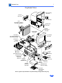
1
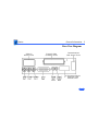
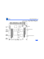
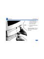
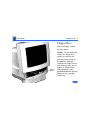
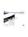
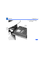
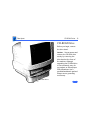
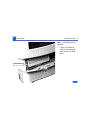
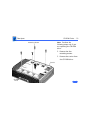
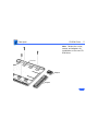
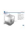
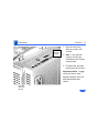
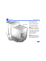
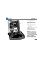
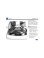
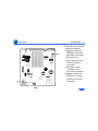
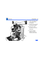
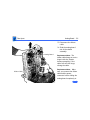
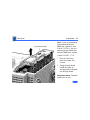
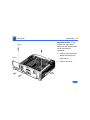
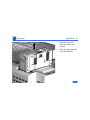
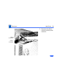
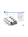
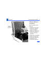
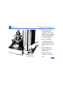
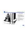
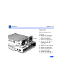
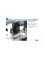
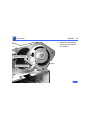
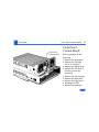
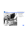
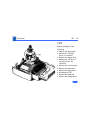
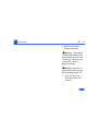
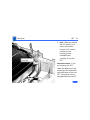
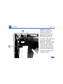
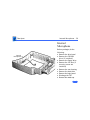
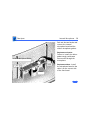
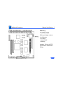
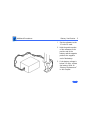
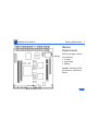
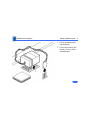
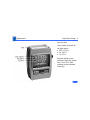
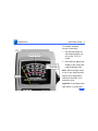
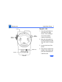
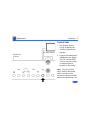
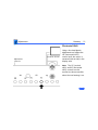
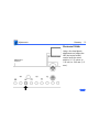
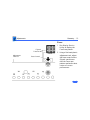
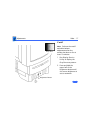
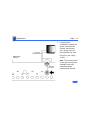
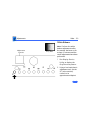
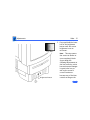
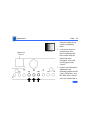
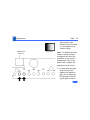
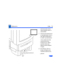
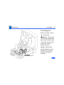
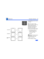
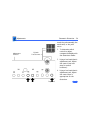
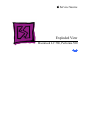
K Service Source
Macintosh LC 580/
Performa 580CD
K Service Source
Basics
LC580/Performa 580CD
Basics
General Information - 1
General Information
Overview
These computers are higher-performance versions of the
Macintosh LC 575. Each features a 33 MHz 68040 logic
board with 4 MB of soldered DRAM (expandable to 52 MB
with two 72-pin SIMMs, 80 ns or less).
Macintosh LC 580
The Macintosh LC 580 supports various options, including
an IDE hard drive and a trayloading double-speed CD-ROM
drive.
Basics
General Information - 2
Performa 580CD
Performa versions of Macintosh products include specific
bundles of software and hardware configurations.
The Performa 580CD is bundled with a 500 MB IDE hard
drive and a trayloading double-speed CD-ROM drive.
The information in this manual is applicable to both the
Macintosh and Performa versions unless specified
otherwise.
Basics
General Information - 3
Rear View Diagram
Video-In
Access Cover
External Video
Connector Cover
Communications
Card Access Cover
LC Processor-Direct
Expansion Card
Access Cover
Basics
General Information - 4
External Video
Connector Slot
Video-In
Slot
SIMMs
Single or
Double
Bank Slot
SIMMs
Single
Bank Slot
Cudo
Reset
Button
Logic Board Diagram
Battery
Communications
Slot
LC Processor-Direct
Slot
K Service Source
Specifications
LC 580/Performa 580CD
Specifications
Processor - 1
Processor
Motorola 68LC040 microprocessor
33 MHz
Built-in memory management unit (MMU)
Specifications
Memory - 2
Memory
RAM
4 MB of dynamic RAM on board
Expandable to 52 MB (fast-paced mode 80 ns DRAM SIMMs)
Two 72-pin SIMM connectors
ROM
1 MB of ROM
PRAM
256 bytes of parameter memory
Long-life lithium battery
VRAM
1 MB of DRAM soldered to logic board
Can display thousands of colors (16-bit)
Specifications
Disk Storage - 3
Disk Storage
Floppy Drive
Built-in 1.4 MB Apple SuperDrive, manual-inject
Hard Drive
Internal IDE hard drive
CD-ROM Drive
Optional internal CD-ROM drive
Specifications
I/O Interfaces - 4
I/O Interfaces
Serial
SCSI
Apple Desktop Bus
Two RS-232/RS-422 serial ports for external modem and
printer
Modem port uses a 9-pin mini-DIN connector
Printer port uses an 8-pin mini-DIN connector
One SCSI port for expansion
Accommodates up to six external SCSI devices
One AppleDesktop (ADB) port for keyboard and mouse
Maximum of three ADB devices recommended
Maximum current draw: 500 mA(Mouse draws 10 mA; keyboard
draws 25 mA.)
Specifications
Sound
I/O Interfaces - 5
Sound-input port for monaural sound input
Sound-output port capable of delivering 8-bit stereo sound
Stereo headphone jack capable of delivering 8-bit stereo sound
Processor-Direct Slot
Internal expansion slot for 114-pin processor-direct expansion
card
Communications
Slot
Internal expansion slot for optional 112-pin fax modem or
Ethernet card
Video-In Slot
Internal, 60-pin video-in slot for optional expansion card that
provides real-time video display, capture, and overlay
External Video
Connector Slot
One 22-pin connector for a second monitor
Specifications
I/O Devices - 6
I/O Devices
Keyboard
Supports all Apple Desktop Bus (ADB) keyboards
Mouse
Apple Desktop Bus Mouse II
Mechanical tracking, optical shaft, or contact encoding
Microphone
Integrated microphone for mono sound input
Speaker
Integrated stereo speakers capable of delivering 8-bit stereo
sound
Specifications
Sound and Video - 7
Sound and Video
Sound Generator
Records at 11 kHz or 22 kHz sample rate
Plays back at 11 kHz or 22 kHz sample rate
Two speakers with enhanced stereo sound
With optional CD-ROM drive, allows playback of ordinary audio
compact discs
Specifications
Video Display
Sound and Video - 8
14-in. diagonal, high-resolution screen (11.5-in. viewable
image)
Gun Configuration: Horizontal inline
Phosphor (aluminized): P22 derivative
Phosphor CIE Coordinates:
Red
x = 0.625 ± 0.020, y = 0.340 ± 0.020
Green x = 0.280 ± 0.020, y = 0.595 ± 0.020
Blue
x = 0.155 ± 0.015, y = 0.070 ± 0.015
Dot Pitch: 0.28 mm dot pitch shadow mask
Vertical Frequency: 66.7 Hz
Active Raster Size (nominal): 9.5 in. by 7.3 in. (240 mm by 180
mm)
White Point: 9300° K
Shipping Brightness (nominal): 30 ± 5 foot lamberts
Specifications
Video Timings
Horizontal Timing
Vertical Timing
Sound and Video - 9
640 x 480 Resolution @ 66.67 Hz
Back Porch: 96 dots
H SYNC: 64 dots
Front Porch: 64 dots
1 dot: 33.06878 ns
1 H: 28.5714 µs
1/dot: 30.24 MHz
Back Porch: 39 H
V SYNC: 3 H
Front Porch: 3 H
1 H: 28.5714 µs
1/H: 35.000 kHz
1 V: 15.000 ms
Specifications
External Video
Connector
(Optional)
Sound and Video - 10
Supports video mirroring on the following external monitors (at
product introduction):
• 640 x 480 resolution: Macintosh 12” Color Display, Apple
Color Plus 14” Display, Apple Performa Plus Display, Apple
Multiple Scan 15 Display, Apple Multiple Scan 17 Display,
Apple Multiple Scan 20 Display
• 800 x 600 resolution: Apple Multiple Scan 15 Display, Apple
Multiple Scan 17 Display, Apple Multiple Scan 20 Display, and
SVGA monitors
Specifications
Physical and Electrical - 11
Physical and Electrical
Dimensions
Weight
Power Supply
Height: 17.9 in. (45.5 cm)
Width: 13.5 in. (34.4 cm)
Depth: 16.5 in. (42.0 cm)
40.5 lb. (18.4 kg)
Voltage: 90 to 264 V rms
Frequency: 50–60 Hz, plus or minus 3 Hz, single phase
Surge Voltage: 300 V rms for 100 ms
Peak Inrush Current: 40 amps pk
Current: 2.0 amps maximum for all line and load conditions
Power: 120 W maximum for all line and load conditions
Line voltage: 100–240 VAC; RMS automatically configured
Specifications
Audio Amplifier
Physical and Electrical - 12
Amplifier drives a 16-ohm speaker
Audio Input Voltage: 0.707 V rms
Audio Input Impedance: 10 K ohms
Output Power at 1 kHz: 250 mW
Bandwidth 3 dB: 200 Hz to 15 kHz
Total Harmonic Distortion: ≤ 1%
Specifications
Environmental - 13
Environmental
Temperature
Operating: 50–104° F (10–40° C)
Transit: (72 hours): -40° F to +149° F (-40° C to +65° C)
Storage (6 months): -40 to 116.6° F (-40 to 47° C)
Relative Humidity
20–95% noncondensing
Operating Altitude
0–10,000 ft. (0–3,000 m)
K Service Source
Troubleshooting
LC 580/Performa 580CD
Troubleshooting
General/ - 1
General
The Symptom Charts included in this chapter will help you
diagnose specific symptoms related to your product. Because cures
are listed on the charts in the order of most likely solution, try
the first cure first. Verify whether or not the product continues to
exhibit the symptom. If the symptom persists, try the next cure.
(Note: If you have replaced a module, reinstall the original module
before you proceed to the next cure.)
If you are not sure what the problem is, or if the Symptom Charts
do not resolve the problem, refer to the Flowchart for the product
family.
For additional assistance, contact Apple Technical Support.
Troubleshooting
First Checklist/ - 2
First Checklist
Important: Read this checklist before you replace a module. Avoid
needless module replacement.
Do you know that...
• The CRT raster will not always resemble a perfect rectangle.
CRT tolerances allow for some distortion. Additional distortion
can be caused by magnetized metal objects (desks, file
cabinets, etc.). Move the unit to a different location if you
notice raster bowing or bent raster edges.
• Jitter, faint lines, or screen movement can be caused by
external interference such as electronic devices and
fluorescent lights. Move the unit to another room or building to
help determine if external interference is the source of the
problem.
• A misadjusted screen can mimic the same symptoms as analog
Troubleshooting
First Checklist/ - 3
board or CRT failures. By performing the adjustment
procedures, you might determine if one or more of the
adjustments is the cause of the problem.
• CRTs rarely fail. Needless CRT replacements can be prevented
by checking display adjustments, checking the possibility of
other defective modules, and accepting small imperfections in
screen display.
If you have any doubts about whether a CRT needs replacement,
contact Apple Technical Support.
Troubleshooting
Symptom Charts/Audio - 4
Symptom Charts
Audio
Sound distortion with
MPEG board installed
Replace MPEG board with modified MPEG board. A modified board
should have a jumper present from U5 Pin 2 to D1 Pin 1.
Troubleshooting
Symptom Charts/Video - 5
Video
Screen is black, too
dark, or too bright;
audio and drive
operate
1
2
3
4
5
6
Screen is bright and
audio is present, but
no video information
is visible
1
2
Adjust contrast button on front bezel.
Adjust brightness button on front bezel.
Check yoke cable connection.
Perform video adjustments. Refer to “Video” in Adjustments
chapter.
Replace analog board.
Replace CRT.
Perform video adjustments. Refer to “Video” in Adjustments
chapter.
Replace analog board.
Troubleshooting
Symptom Charts/Video (Continued) - 6
Video (Continued)
Screen is completely
black except for
single vertical or
horizontal line
displayed
1
2
3
Predominant color
tint or color cannot be
adjusted
Perform video adjustments. Refer to “Video” in Adjustments
chapter.
Picture breaks into
diagonal lines, or
picture rolls
vertically or
horizontally
1
2
Check yoke cable connection with power off.
Replace analog board.
Replace CRT.
Perform geometry adjustments. Refer to “Geometry” in
Adjustments chapter.
Replace analog board.
Troubleshooting
Symptom Charts/Video (Continued) - 7
Video (Continued)
Out of convergence
(color bleeds from
text or lines)
1
2
Black screen spots
(burnt phosphors)
Perform convergence adjustment. Refer to “Convergence” in
Adjustments chapter. Note that some misconvergence is
normal, especially around edges of screen. Contact Apple
Technical Support if you’re uncertain whether the
misconvergence is within specification.
Replace analog board.
Replace CRT.
Troubleshooting
Symptom Charts/Video (Continued) - 8
Video (Continued)
Screen jitters or
flashes
1
2
3
Out of focus
1
2
3
Refer to “First Checklist” in this chapter. Move electrical
devices (other monitors, scanners, etc.) away from monitor.
Temporarily shut off all fluorescent lights in area.
Move unit to another room or building and check if symptom
persists.
Replace analog board.
Perform focus adjustment. Refer to “Focus” in Adjustments
chapter. Note that misconvergence can also produce an outof-focus symptom.
Check for proper screen luminance. If luminance is off,
perform cutoff and white balance adjustments. Refer to
“Video” in Adjustments chapter.
Replace analog board.
Troubleshooting
Symptom Charts/Video (Continued) - 9
Video (Continued)
Raster size too short/
tall or narrow/wide
1
Linearity bad (size of
text/graphics differs
at top, bottom, or
sides of screen)
Replace analog board.
2
Perform geometry adjustment. Refer to “Geometry” in
Adjustments chapter.
Replace analog board.
Troubleshooting
Symptom Charts/Video (Continued) - 10
Video (Continued)
Raster tilted or
shifted
1
2
3
4
Raster distorted
(barrel-shaped,
corners not square,
stretched or
compressed at top of
display, or sides not
perpendicular)
1
2
3
Refer to “First Checklist” in this chapter. Move metal
objects away from monitor.
If symptom appears immediately after CRT replacement,
reinstall CRT and align it according to CRT guidelines in the
Take Apart chapter
Perform appropriate geometric adjustments (see
Adjustments chapter).
Replace analog board.
Refer to “First Checklist” in this chapter. Move metal
objects away from monitor.
Perform appropriate geometric adjustments (see
Adjustments chapter).
Replace analog board.
Troubleshooting
Symptom Charts/Video (Continued) - 11
Video (Continued)
Raster not centered
1
2
Adjust horizontal or vertical shift control. Refer to
Adjustments chapter.
Refer to “First Checklist” in this chapter.
Troubleshooting
Symptom Charts/Floppy Drive - 12
Floppy Drive
Audio and video are
present, but internal
floppy drive does not
operate
1
2
3
Replace bad disk with known-good disk.
Replace floppy drive.
Replace logic board. Retain customer’s SIMMs.
Disk ejects; display
shows icon with
blinking “X”
1
2
3
Replace bad system disk with known-good system disk.
Replace floppy drive.
Replace logic board. Retain customer’s SIMMs.
Unable to insert disk
all the way
1
To eject previously inserted disk, insert opened paper clip
into hole beside floppy drive.
Switch off system and hold mouse button down while
switching system on (to complete eject cycle).
Replace floppy drive.
2
3
Troubleshooting
Symptom Charts/Floppy Drive (Continued) - 13
Floppy Drive (Continued)
Does not eject disk
Internal floppy drive
runs continuously
1
2
3
Insert opened paper clip into hole beside floppy drive.
Switch off system and hold mouse button down while
switching system on (to complete eject cycle).
Replace floppy drive.
1
2
3
Replace bad disk with known-good disk.
Replace floppy drive.
Replace logic board. Retain customer’s SIMMs.
Troubleshooting
Symptom Charts/Hard Drive - 14
Hard Drive
Internal or external
hard drive does not
operate
1
2
3
4
5
Verify that SCSI loopback card is not attached.
Verify that external drive is properly terminated.
Replace hard drive.
Replace logic board. Retain customer’s SIMMs.
Replace hard drive.
Troubleshooting
Symptom Charts/CD-ROM Drive - 15
CD-ROM Drive
CD-ROM drive does
not accept disc
1
2
Replace disc (if dirty or damaged).
Replace CD-ROM drive mechanism.
Volume control does
not operate correctly
1
2
3
4
Reseat CD adapter connector.
Replace CD adapter connector.
Replace CD-ROM drive.
Replace chassis harness assembly.
Macintosh cannot
mount CD-ROM drive
1
2
Reseat CD adapter connector.
Check SCSI ID setting. (Internal CD-ROM was originally set
to 3 at factory.)
Test CD-ROM drive on known-good Macintosh; if CD-ROM
drive doesn’t work, replace it.
Replace chassis harness assembly.
3
4
Troubleshooting
Symptom Charts/CD-ROM Drive (Continued) - 16
CD-ROM Drive (Continued)
When an internal and
external SCSI device
are present, only one
powers up
1
2
3
Verify that SCSI device ID switch setting on external device
is higher than 0. Verify that ID switch setting on external
SCSI device does not duplicate ID switch settings on other
external SCSI devices.
Replace terminator on external SCSI device.
Replace SCSI select cable.
Troubleshooting
Symptom Charts/CD-ROM Drive (Continued) - 17
CD-ROM Drive (Continued)
A Macintosh LC 580
starts up from a
backup CD-ROM disc,
but won’t eject the
disc and gives a -50
error. Or the
computer starts up
from backup CDROM, but won’t mount
discs after restart.
Early Macintosh LC 580 computers shipped with AppleCD 300i
plus CD-ROM drives. Later LC 580 computers shipped with
AppleCD 600i CD-ROM drives. Using a backup CD-ROM intended
for the AppleCD 300i in an AppleCD 600i (or vice versa) will
cause these symptoms.
• Identify the backup CD-ROM discs by their part numbers.
Backup discs for AppleCD 300i have the part numbers
691-0462-B or 691-3305-A. Backup discs for AppleCD
600i have the part number 691-0793-A.
• Identify the CD-ROM drive installed in the Macintosh LC
580. Remove any CD-ROM disc present in the drive. Open
the PC Exchange control panel and click Options. You will
see the product code CR-8004x if the drive is a 300i or
the code CR-8005x if the drive is a 600i.
• Use only 300i backup CD-ROM discs in 300i drives, and
only 600i backup discs in 600i drives.
Troubleshooting
Symptom Charts/Peripheral - 18
Peripheral
Cursor does not move
Cursor moves, but
clicking mouse
button has no effect
1
2
3
4
Check mouse connection.
If mouse was connected to keyboard, connect it to rear ADB
port instead. If mouse works, replace keyboard.
If mouse does not work in any ADB port, replace mouse.
Replace logic board. Retain customer’s SIMMs.
1
2
Replace mouse.
Replace logic board. Retain customer’s SIMMs.
Troubleshooting
Symptom Charts/Peripheral (Continued) - 19
Peripheral (Continued)
Cannot double-click
to open application,
disk, or server
1
2
4
5
Remove extra system files on hard drive.
Clear parameter RAM. Hold down <Command> <Option> <P>
<R> keys during system startup but before “Welcome to
Macintosh” appears.
If mouse was connected to keyboard, connect it to rear ADB
port instead. If mouse works, replace keyboard.
If mouse does not work in any ADB port, replace mouse.
Replace logic board. Retain customer’s SIMMs.
1
2
3
4
Check keyboard connection to ADB port.
Replace keyboard cable, if detachable.
Replace keyboard.
Replace logic board. Retain customer’s SIMMs.
3
No response to any
key on keyboard
Troubleshooting
Symptom Charts/Peripheral (Continued) - 20
Peripheral (Continued)
Known-good
ImageWriter or
ImageWriter II does
not print
1
2
Known-good
LaserWriter does not
print
1
2
3
4
3
Make sure that Chooser and Control Panel are set correctly.
Replace printer driver and system software with knowngood.
Replace printer interface cable.
Replace logic board. Retain customer’s SIMMs.
Make sure that Choose and Control Panel are set correctly.
Replace printer driver and system software with knowngood.
Troubleshoot by referring to Apple Service Guide for
Networking and Communications.
Troubleshooting
Symptom Charts/Peripheral (Continued) - 21
Peripheral (Continued)
When an internal and
external SCSI device
are present, only one
powers up
1
2
3
Verify that SCSI device ID switch setting on external device
is higher than 0. Verify that ID switch setting on external
SCSI device does not duplicate ID switch settings on other
external SCSI devices.
Replace terminator on external SCSI device.
Replace SCSI select cable.
Troubleshooting
Symptom Charts/Global Village Modem “Busy Serial Port” - 22
Global Village Modem “Busy Serial Port”
Using modem gives
message: “Can’t find
or can’t access a
modem to use for
registration. Make
sure you have Global
Village software
installed correctly,
reboot your
computer, and try
again. If you want to
use a specific modem
for registration,
select it from
Chooser.”
The TelePort Control Panel becomes corrupted when a Performa
580CD is restarted while AppleTalk is set to “Inactive” in the
Chooser or LocalTalk is not the selected AppleTalk Connection in
the Network Control Panel. Follow these steps;
1
2
3
4
5
6
Obtain GlobalFax 2.5.2P Update.
Restart the computer with extensions off.
Double-click Performa GlobalFax 2.5.2 Update icon.
Click Update button and watch for update confirmation
window.
Restart computer.
Customer should keep backup copy of 2.5.2 Update program
and run it after reinstalling software from backup CD.
Troubleshooting
Symptom Charts/Global Village Modem “Busy Serial Port” - 23
Global Village Modem “Busy Serial Port”
Resetting modem in
TelePort Control
Panel gives message:
“The current port is
busy and cannot be
opened. Quit any open
communication
application, or turn
off AppleTalk in the
Chooser (if the
modem is connected to
the Printer port),
and then reopen the
TelePort control
panel.”
Here’s an alternative fix that doesn’t require GlobalFax 2.5.2P
Update:
1
2
Replace corrupted control panel in System Folder with
uncorrupted copy of TelePort Control Panel found in Control
Panels folder on backup CDs.
Set AppleTalk to “Active” and select LocalTalk as the
AppleTalk Connection in Network Control Panel.
Troubleshooting
Symptom Charts/Miscellaneous - 24
Miscellaneous
Clicking, chirping,
or thumping sound
1
2
Replace analog board.
Replace logic board. Retain customer’s SIMMs.
Smoke/odor
Replace analog board.
No video, no audio, and
no drive operation
1
2
3
4
5
Connect power cord.
Switch power on.
Replace power cord.
Replace analog board.
Replace logic board. Retain customer’s SIMMs.
“Sad Macintosh” icon
1
2
3
Replace bad disk with known-good disk.
Replace RAM SIMMs on logic board.
Replace logic board. Retain customer’s SIMMs.
Troubleshooting
Symptom Charts/Miscellaneous (Continued) - 25
Miscellaneous (Continued)
Screen shows “Sad
Macintosh” icon and
black vertical lines;
screeching sound
1
2
Replace RAM SIMMs on logic board.
Replace logic board. Retain customer’s SIMMs.
Headphone jack does
not operate correctly
1
2
3
Verify that headphone jack is seated properly.
Replace front panel control board.
Replace chassis harness assembly.
No sound from
external speakers
1
Check that volume is turned on (manually or through Control
Panel).
Verify that headphones are unplugged.
Verify that speaker connectors are properly connected.
Test speakers with known-good Macintosh; if speakers do not
work, replace them.
Replace logic board.
2
3
4
5
K Service Source
Take Apart
LC 580/Performa 580CD
Take Apart
Drive Bezel - 1
Drive Bezel
No preliminary steps are
required before you begin
this procedure.
Caution: Review ESD
precautions in Bulletins/
Safety.
Drive
Bezel
Take Apart
Drive Bezel - 2
1
Note: Place the unit
near the edge of the work
table.
Insert a flat-blade
screwdriver into the
opening on the bottom of
the drive bezel.
Drive
Bezel
Take Apart
Drive Bezel - 3
2
Drive
Bezel
3
Push the blade away
from you, twisting it to
release the interior
latch on the bezel.
Pull the bezel down and
remove it.
Replacement Note: Slide the
bezel up and firmly snap it
into place.
Take Apart
Floppy Drive - 4
Floppy Drive
Before you begin, remove
the drive bezel.
Floppy
Drive
Caution: You can access and
remove the floppy drive
merely by removing the
drive bezel at the front of
the machine. Although
replacing the floppy drive is
now extremely easy, do not
neglect to follow proper
ESD precautions: Use a
grounded workbench pad and
always wear a grounding
wriststrap.
Take Apart
Floppy Drive - 5
1
Floppy
Drive
Latch
Push up the latch and
pull out the floppy drive.
Take Apart
Floppy Drive - 6
2
Floppy
Drive
Floppy
Drive
Cable
Disconnect the floppy
drive cable.
Take Apart
Floppy Drive - 7
Mounting Screw
Note: Perform the following
steps only if you are
replacing the floppy drive.
3
Carrier
4
Floppy
Drive
Note: Notice the
placement of the carrier
and screws before
removing them. Retain
the carrier and screws
and install them on the
new floppy drive.
Remove the four
mounting screws.
Remove the carrier from
the floppy drive.
Take Apart
CD-ROM Drive - 8
CD-ROM Drive
Before you begin, remove
the drive bezel.
Caution: You can access and
remove the CD-ROM drive
merely by removing the
drive bezel at the front of
the machine. Although
upgrading the CD-ROM drive
is now extremely easy, do
not neglect to follow proper
ESD precautions: Use a
grounded workbench pad and
always wear a grounding
wriststrap.
CD-ROM Drive
Take Apart
CD-ROM Drive - 9
Note: A CD-ROM drive is
optional.
1
CD-ROM Drive
Using a screwdriver,
push up the latch and
slide out the CD-ROM
drive.
Take Apart
CD-ROM Drive - 10
Note: Perform the
following steps only if you
are replacing the CD-ROM
drive.
Mounting Screw
2
3
Carrier
CD-ROM
Drive
Remove the four
mounting screws.
Remove the carrier from
the CD-ROM drive.
Take Apart
CD-ROM Drive - 11
Note: Retain the carrier,
screws, and adapters for
installation on the new CDROM drive.
Carrier
Adapter
Adapter
Take Apart
I/O Door - 12
I/O Door
No preliminary steps are
required before you begin
this procedure.
Caution: To prevent ESD
damage to components, wear
a grounding wriststrap.
Review ESD precautions in
Bulletins/Safety.
I/O Door
Take Apart
I/O Door - 13
Tab
Tab
1
Optional
Optional
Security
Security
Screw
Screw
2
3
Place the unit facedown on a clean, soft
surface.
Note: If the optional
security screws are
installed on the I/O door,
remove them.
Pull down the two tabs
and remove the I/O door.
Replacement Note: Engage
the three interior tabs
along the bottom of the I/O
door and snap the door
closed.
Optional
Security
Screw
Take Apart
Rear Housing - 14
Rear Housing
Rear Housing
Before you begin, remove
the I/O door (if security
screws are installed)
Warning: This product
contains high voltage and a
high-vacuum picture tube.
To prevent serious injury,
review CRT safety in
Bulletins/Safety.
±
Never use a
grounding wriststrap until
after discharging the CRT.
±Warning:
Take Apart
Rear Housing - 15
1
Mounting
Screw
I/O Door
Foot
Foot
Rear Housing
Foot
Note: If the I/O door is not
secured by screws, leave it
in place and it will
automatically be removed
with the rear housing.
2
Foot
Place the unit facedown on a clean, soft
surface.
3
Using a Torx
screwdriver, remove
the five mounting
screws.
Pry open the unit with a
case cracker and lift off
the rear housing.
Take Apart
Rear Housing - 16
Replacement Note: If the
feet on the rear housing are
worn, replace them.
Take Apart
Fan - 17
Fan
Fan
Before you begin, remove
the following:
• I/O door (if security
screws are installed)
• Rear housing
Warning: This product
contains high voltage and a
high-vacuum picture tube.
To prevent serious injury,
review CRT safety in
Bulletins/Safety.
±
Take Apart
Fan - 18
Latch
Never use a
grounding wriststrap until
after discharging the CRT.
±Warning:
Push the latches outward and
remove the fan assembly.
Latch
Take Apart
Analog Board - 19
Analog Board
Analog Board
Before you begin, do the
following:
• Remove the I/O door (if
security screws are
installed)
• Remove the rear housing
• Discharge the CRT
• Remove the anode cap
This product
contains high voltage and a
high-vacuum picture tube.
To prevent serious personal
injury or equipment
damage, discharge the CRT
and remove the anode cap.
±Warning:
Take Apart
Analog Board - 20
Review CRT safety in
Bulletins/Safety. Unlike
other monitors, the LC 580
monitor must be face-down
when the CRT is discharged.
Ground
Cable
Ground
Cable
Never use a
grounding wriststrap until
after discharging the CRT.
±Warning:
1
2
Caution: Place the unit
face down on a clean, soft
surface. This will
prevent stress on the
front bezel, which could
cause the bezel to crack.
Disconnect the two
ground cables.
Take Apart
Analog Board - 21
3
BP2
Disconnect the following
analog board cables:
• Degauss cable from
BP2(Black and white,
with white connector)
• CRT cable from
BD1(Long and multicolored, with gray
connector)
• Microphone cable
from BD8 (Gray,
with white connector)
• Speaker cable from
SSI(Short and multi
colored, with brown
connector)
Take Apart
Analog Board - 22
4
CRT/
Video
Board
Connector
CRT/Video
Board
Remove the degauss
wires from the cable
retainer, located at
HLD3.
Replacement Note: If you
are replacing the analog
board, remove the cable
retainer and reinstall it on
the new board.
5
Caution: Twisting,
bending, or applying
force to the CRT/video
board could damage the
neck of the CRT. Be sure
Gray
to pull the CRT/video
Epoxy
board straight off the
CRT.
Take Apart
Analog Board - 23
Note: If gray epoxy
secures the CRT/video
board, cut and peel it off
before removing the
board.
Analog Board Guide
Analog
Board
Guide
6
7
Release
Tab
Remove the CRT/video
board from the neck of
the CRT.
Disconnect the small,
pink CRT/video board
connector.
Note: The analog board
is supported by a plastic
guide on each side.
Take Apart
Analog Board - 24
8
9
Push in the release tab
on one of the analog
board guides.
Grasp the fence and pull
the board up slightly.
10 Perform the same
procedure on the other
release tab.
11 Pull up the board
slightly to expose a
connector and a cable.
Power
Connector
Take Apart
Analog Board - 25
12 Disconnect the white
power connector.
Power
Connector
Replacement Note: Move
aside the loose analog board
cables so they do not extend
below the board as you slide
it in.
Replacement Note: Push the
power connector cables fully
into the EMI shielding.
Failure to do so could cause
the wires to wear.
Take Apart
Analog Board - 26
13 Disconnect the ribbon
cable.
Analog Board
Ribbon Cable
14 Slide the analog board
out of the chassis
assembly.
Replacement Note: The
ribbon cable hangs on a wire
hinge inside the chassis
harness assembly. If the
cable falls off this hinge,
rehang the cable.
Replacement Note: Make
sure you connect the ribbon
cable and the power
connector before sliding the
analog board completely in.
Take Apart
Analog Board - 27
Replacement Note:
Perform the cutoff
adjustment whenever you
replace the analog board. See
“Video” in the Adjustments
chapter.
Take Apart
Logic Board - 28
Logic Board
Before you begin, remove
the I/O door.
Logic
Board
Caution: You can access and
remove the logic board
merely by removing the I/O
door at the rear of the
machine. Although upgrading
the logic board is now
extremely easy, do not
neglect to follow proper
ESD precautions: Use a
grounded workbench pad,
and always wear a
grounding wriststrap.
Take Apart
Logic Board - 29
Logic Board Handle
Note: If you are replacing a
logic board that has one
SIMM slot, replace it with
P/N 661-0158. If you are
replacing a logic board that
has two SIMM slots, replace
it with P/N 661-1114.
1
2
Place the unit facedown on a clean, soft
surface.
Swing the logic board
handle out from its
storage position and pull
out the logic board.
Replacement Note: Snap the
handle into its slot.
Take Apart
Logic Board - 30
Replacement Note: If you
replace the logic board,
make sure the battery cable
on the new board is
connected.
Screw
3
Fence
4
Logic
Board
Remove the screws that
attach the fence to the
logic board.
Remove the fence.
Take Apart
Logic Board - 31
Replacement Note: If the
logic board rails are
damaged, replace them. You
will need to remove the rear
housing in order to access
the rails.
Logic Board Rail
Chassis Harness
Assembly
Take Apart
Hard Drive - 32
Hard Drive
Before you begin, remove
the I/O door.
Caution: You can access and
remove the hard drive
merely by removing the I/O
door at the rear of the
machine. Although upgrading
the hard drive is now
extremely easy, do not
neglect to follow proper
ESD precautions: use a
grounded workbench pad,
and always wear a
grounding wriststrap.
Hard Drive
Take Apart
Hard Drive - 33
1
2
Place the unit facedown on a clean, soft
surface.
Push the latch and slide
out the hard drive.
Take Apart
Hard Drive - 34
3
Ribbon
Connector
Power
Connector
Disconnect the ribbon
connector and the power
connector.
Take Apart
Hard Drive - 35
Mounting Screw
Carrier
Note: Perform the following
steps only if you are
replacing the hard drive.
Note: Notice the placement
of the carrier and screws
before removing them.
Retain the carrier and
screws and install them on
the new hard drive.
4
5
Hard Drive
Remove the four screws.
Remove the carrier from
the hard drive.
Take Apart
Hard Drive - 36
Replacement Caution: Some
hard drives have jags near
the cable connector that can
rub and, therefore, damage
the cable. When reinstalling
one of these drives, fold the
cable and slide it in so that it
precedes the drive into the
chassis harness assembly.
Take Apart
Chassis Harness Assembly - 37
Chassis Harness
Assembly
Chassis
Harness
Assembly
Before you begin, do the
following:
• Remove the drive bezel
• Remove the CD-ROM
drive (if installed)
• Remove the floppy drive
• Remove the I/O door (if
security screws are
installed)
• Remove the rear housing
• Remove the hard drive
• Remove the logic board
• Discharge the CRT
• Remove the anode cap
Take Apart
Chassis Harness Assembly - 38
• Remove the analog board
This product
contains high voltage and a
high-vacuum picture tube.
To prevent serious injury,
review CRT safety in
Bulletins/Safety.
±Warning:
Never use a
grounding wriststrap until
after discharging the CRT.
±Warning:
Take Apart
Chassis Harness Assembly - 39
Caution: Place the unit face
down on a clean, soft
surface. This will prevent
stress on the front bezel,
which could cause the bezel
to crack.
Note: A chassis guide and a
plastic tab secure each side
of the chassis to the front
housing. Before lifting off
the chassis, you must
remove the guides and
release the tabs.
Top Opening
Chassis Guide
Chassis Guide
Take Apart
Chassis Harness Assembly - 40
1
2
3
Using a flat-blade
screwdriver, press in
the bottom of the chassis
guide and release its
latch.
Without removing the
screwdriver, place a
finger in the top opening
and firmly slide the
guide up and off.
Perform the same
procedure on the other
chassis guide.
Take Apart
Chassis Harness Assembly - 41
4
5
6
Chassis Opening
for Interior Tab
7
Slide your hand from
the far side of the
assembly to the section
closest to you. Locate the
plastic tab hidden inside
the chassis opening.
Insert a flat-blade
screwdriver into the
chassis opening. Push in
and release the interior
tab.
Pull the chassis up
slightly and hold it in
that position.
Perform the same
procedure on the other
side.
Take Apart
Chassis Harness Assembly - 42
8
Lift off the chassis
harness assembly.
Replacement Note: To
prevent the speaker cable
from getting caught beneath
the chassis, move the cable
to the side.
Replacement Note: Align the
chassis opening with the
plastic tab on the front
housing.
Chassis Opening
and Interior Tab
Take Apart
Chassis Harness Assembly - 43
Analog Board Guide
Replacement Note: If the
analog board guides are
damaged, replace them.
Before removing them,
notice how they are
installed, since there is a
left-side and a right-side
guide. Insert a flat-blade
screwdriver under the
analog board guide and push
the guide up. Slide the guide
forward and remove it.
Take Apart
Speakers - 44
Speakers
Speaker
Speaker
Before you begin, do the
following:
• Remove the drive bezel
• Remove the CD-ROM
drive (if installed)
• Remove the floppy drive
• Remove the I/O door (if
security screws are
installed)
• Remove the rear housing
• Remove the hard drive
• Remove the logic board
• Discharge the CRT
• Remove the anode cap
• Remove the analog board
Take Apart
Speakers - 45
2
• Remove the chassis
harness assembly
Note: Perform the following
steps on each speaker.
1
1
Remove two screws from
the speaker.
Take Apart
Speakers - 46
2
Speaker
Disconnect the speaker
connectors and remove
the speaker.
Take Apart
Front Panel Control Board - 47
Front Panel
Control Board
Front Panel
Control Board
Before you begin, do the
following:
• Remove the drive bezel
• Remove the CD-ROM
drive (if installed)
• Remove the floppy drive
• Remove the I/O door (if
security screws are
installed)
• Remove the rear housing
• Remove the hard drive
• Remove the logic board
• Discharge the CRT
• Remove the anode cap
Take Apart
Front Panel Control Board - 48
• Remove the analog board
• Remove the chassis
harness assembly
Front Panel
Control Board
1
2
Screw
Remove the screw.
Lift off the front panel
control board.
Take Apart
Front Panel Control Board - 49
3
Shield
Note: Notice how the
shield is installed—with
the lip covering the
cable—before removing
it.
Remove the shield from
the board and disconnect
the cable.
Cable
Replacement Note: Make
sure you connect the cable
before installing the shield.
Lip
Shield
Replacement Note: Slide the
board onto the two front
metal tabs on the chassis.
Push the board firmly into
place and install the screw.
Take Apart
CRT - 50
CRT
Before you begin, do the
following:
• Remove the drive bezel
• Remove the CD-ROM
drive (if installed)
• Remove the floppy drive
• Remove the I/O door (if
security screws are
installed)
• Remove the rear housing
• Remove the hard drive
• Remove the logic board
• Discharge the CRT
• Remove the anode cap
• Remove the analog board
Take Apart
CRT - 51
• Remove the chassis
harness assembly
This product
contains high voltage and a
high-vacuum picture tube.
To prevent serious injury,
review CRT safety in
Bulletins/Safety.
±Warning:
Never use a
grounding wriststrap until
after discharging the CRT.
±Warning:
1
Place the unit facedown on a clean, soft
surface.
Take Apart
CRT - 52
2
CRT
Metallic Tie
Metallic Tie
Degauss
Coil
Metallic
Tie
Metallic Tie
Degauss Cable
Unhinge the four
metallic ties and remove
the degauss coil.
Replacement Note: Replace
the degauss coil so that its
cable hangs on the left side.
Replacement Note: R e hinge the metallic ties
snugly so they hold the CRT
firmly in place.
Take Apart
CRT - 53
3
Mounting Screw
Assembly
Note: When you remove
the CRT, place it on a
clean, soft surface.
Using a 5/16 ratchet,
remove the four
mounting screw
assemblies and
carefully lift out the
CRT.
Replacement Note: If you
are replacing the CRT,
retain the degauss coil and
mounting screw assemblies
and install them on the new
CRT. These parts are not
packaged with the new CRT
Take Apart
CRT - 54
and are not available
individually.
Replacement Note: If the
rubber washers on the
front housing are worn,
replace them.
Replacement Note: Before
installing the CRT, be sure
the microphone cable is not
caught under the CRT.
Replacement Note: Make
sure the CRT is replaced
correctly, with the anode
cap near the top of the front
bezel.
Take Apart
CRT - 55
Front Bezel
CRT
Rib
Replacement Caution:
Failure to install the CRT
correctly will make it
difficult to perform video
adjustments. To align the
CRT, push it against the
second rib in the front bezel
top. Next, slide the CRT
against the second rib in the
bezel side. Holding the CRT
firmly in place, install a
mounting screw assembly,
which will partially secure
the CRT to the bezel. Install
mounting assemblies in the
remaining corners.
Take Apart
Internal Microphone - 56
Internal
Microphone
Internal
Microphone
Before you begin, do the
following:
• Remove the drive bezel
• Remove the CD-ROM
drive (if installed)
• Remove the floppy drive
• Remove the I/O door (if
security screws are
installed)
• Remove the rear housing
• Remove the hard drive
• Remove the logic board
• Discharge the CRT
• Remove the anode cap
Take Apart
Internal Microphone - 57
• Remove the analog board
• Remove the chassis
harness assembly
• Remove the CRT
This product
contains high voltage and a
high-vacuum picture tube.
To prevent serious injury,
review CRT safety in
Bulletins/Safety.
±Warning:
Never use a
grounding wriststrap until
after discharging the CRT.
±Warning:
Take Apart
Internal Microphone - 58
Push out the two latches and
remove the internal
microphone board and the
rubber microphone gasket.
Replacement Caution:
Failure to install the rubber
gasket snugly could cause
excess noise through the
microphone.
Internal Microphone Board
Gasket
Replacement Note: Install
the microphone board so the
cable is on the correct side
of the front bezel.
Take Apart
Front Bezel - 59
Front Bezel
To remove the front bezel,
do the following:
• Remove the drive bezel
• Remove the CD-ROM
drive (if installed)
• Remove the floppy drive
• Remove the I/O door (if
security screws are
installed)
• Remove the rear housing
• Remove the hard drive
• Remove the logic board
• Discharge the CRT
• Remove the anode cap
• Remove the analog board
Take Apart
Front Bezel - 60
• Remove the chassis
harness assembly
• Remove the CRT
• Remove the internal
microphone
K Service Source
Additional Procedures
LC 580/Performa 580CD
Additional Procedures
Battery Verification - 1
Battery
Verification
Before you begin, remove
the following:
• I/O door
• Logic board
• Battery
Caution: Review the ESD
precautions in Bulletins/
Safety.
Additional Procedures
Battery Verification - 2
1
2
3
Set the voltmeter to the
10 volts DC scale.
Hold the positive probe
of the voltmeter to the
positive end of the
battery and the negative
probe to the negative
end of the battery.
If the battery voltage is
below 3.0 volts, replace
the battery. Refer to
“Battery Replacement”
in this chapter.
Additional Procedures
Battery Replacement - 3
Battery
Replacement
Before you begin, remove
the following:
• I/O door
• Logic board
• Battery
Caution: Review the ESD
precautions in Bulletins/
Safety.
Additional Procedures
Battery Replacement - 4
1
2
Pull up and disconnect
the connector.
Pull up and remove the
battery from its hookand-loop base.
K Service Source
Adjustments
LC 580/Performa 580CD
Adjustments
Light Meter Setup - 1
Light Meter Setup
This topic covers setup for
three light meter models:
R77, L-248, and 246.
Model R77 (Apple part
number 076-0310) is the
newest model available.
Model R77
The R77 light meter is
capable of reading luminance
from 10 to 1,000
footcandles (fc).
Before you begin, remove
the 10X multiplier plate
Adjustments
Light Meter Setup - 2
from the lens.
Three scales are shown on
the light meter:
• 200-1000 fc
• 50-250 fc
• 10-50 fc
Because display screen
luminance typically ranges
from 10 to 50 fc, take
readings from the bottom
scale only.
Adjustments
Light Meter Setup - 3
To measure a display
screen’s luminance,
1
2
Set the scale switch to
the bottom position (to
set up the 10-50 fc
scale).
Place the lens against the
middle of the screen and
read the bottom scale.
Note: When the light meter
is not in use, slide the scale
switch to its top position,
and store the meter in its
protective case.
Important: If you suspect the
light meter is giving false
Adjustments
Light Meter Setup - 4
readings, verify the
readings with a known-good
light meter or photometer.
Also check the age of the R77
light meter by its four-digit
manufacturing date stamp
(such as 0398 for March
1998).
Caution: Dropping the
meter can permanently
damage its accuracy. A
shock-damaged meter might
read incorrectly or its
pointer may not drop to
zero.
Adjustments
Light Meter Setup - 5
Lens
Side
Switch
Model L-248
1
Read
Button
2
3
Red Area
Scale
4
Press the red button on
the back of the light
meter. If the reading is
out of the red area,
replace the battery.
Move the side switch to
its lower position so that
the scale reads 2 through
10.
Uncover the lens of the
meter.
Place the lens against the
middle of the screen and
press the read button to
read the scale.
Adjustments
Light Meter Setup - 6
Model 246
Lens
Swivel Head
1
2
3
Scale
4
Remove the metal slide,
if installed, from the
top of the light meter.
Install the white lens
with the red dot.
Rotate the swivel head
so the lens of the meter
faces the monitor.
Place the lens against the
middle of the screen and
read the scale.
Adjustments
Geometry - 7
Geometry
Before you begin, remove
the rear housing.
This product
contains high voltage and a
high-vacuum picture tube.
To prevent serious injury,
review CRT safety in
Bulletins/Safety.
±Warning:
Adjustment
Controls
Caution: When placed
upright without the rear
housing, the front bezel
becomes vulnerable to
breakage. Avoid
High Voltage Areas
Adjustments
Geometry - 8
overhandling the unit in this
condition.
Note: The controls on this
monitor require a small
hex-head plastic tool to
make adjustments. If the tool
is long, it will be too
flexible, which will make
fine adjustments difficult.
Use a short hex-head
plastic tool to minimize
flexing.
Do not use
metal alignment tools—they
are a shock hazard.
±Warning:
Adjustments
Geometry - 9
Vertical Shift
1
Adjustment
Controls
All-White Screen
2
Run Display Service
Utility to display the
All-White Screen test
pattern.
Using a hex-head plastic
adjustment tool, adjust
the VS (vertical shift)
control until the raster
is centered (top to
bottom) in the screen.
Note: The VS (vertical
shift) and HS (horizontal
shift) controls on this
monitor are also accessible
when the rear housing is on.
Adjustments
Geometry - 10
Horizontal Shift
Adjustment
Controls
All-White Screen
Using a hex-head plastic
adjustment tool, adjust the
HS (horizontal shift)
control until the raster is
centered (side to side) in the
display area.
Note: The VS (vertical
shift) and HS (horizontal
shift) controls on this
monitor are also accessible
when the rear housing is on.
Adjustments
Geometry - 11
Vertical Height
1
Adjustment
Controls
All-White Screen
2
Using a hex-head plastic
adjustment tool, adjust
the VH (vertical height)
control until the raster
height is 7-1/8 inches
(± 1/8 inch) or 180
mm (± 2 mm).
Verify this height. If it
is off, repeat the
vertical height
adjustment and, if
necessary, the vertical
shift adjustment.
Adjustments
Geometry - 12
Horizontal Width
Adjustment
Controls
All-White Screen
Using a hex-head plastic
adjustment tool, adjust the
HW (horizontal width)
control until the raster
width is 9-1/2 inches (±
1/8 inch) or 240 mm (± 2
mm).
Adjustments
Geometry - 13
Focus
1
Flyback
Transformer
Adjustment
Controls
Focus Control
Focus
2
Run Display Service
Utility to display the
Focus test pattern.
Using a flat-head plastic
adjustment tool, adjust
the focus control on the
flyback transformer
until the Focus test
pattern reaches the best
center-of-screen
performance.
Adjustments
Video - 14
Video
Before you begin, remove
the rear housing.
This product
contains high voltage and a
high-vacuum picture tube.
To prevent serious injury,
review CRT safety in
Bulletins/Safety.
±Warning:
Adjustment
Controls
High Voltage Areas
Adjustments
Video - 15
Because
adjustments are made from
the rear of the monitor,
position a mirror to view
the monitor screen. Do not
reach around the monitor to
adjust the controls.
±Warning:
Caution: When placed
upright without the rear
housing, the front bezel
becomes vulnerable to
breakage. Avoid
overhandling the unit in this
condition.
Adjustments
Video - 16
Note: Perform the cutoff
adjustment prior to
adjusting the white balance.
Replacement Note: Perform
the cutoff adjustment
whenever you replace the
CRT or the analog board.
Adjustments
Video - 17
Cutoff
Gray Bars
Note: Perform the cutoff
and white balance
adjustments after the
monitor has been on for at
least 10 minutes.
1
2
Brightness Button
Run Display Service
Utility to display the
Gray Bars test pattern.
Press and hold the
upper half of the
brightness button until
the screen brightness is
set to maximum.
Adjustments
Video - 18
3
Adjustment
Controls
Gray Bars
4
Using a hex-head plastic
adjustment tool, set the
SC (sub-contrast)
control to maximum
(turn clockwise).
Set the RB (red bias),
GB (green bias), and BB
(blue bias) controls to
their minimum
(counterclockwise)
positions.
Note: Setting the bias
controls to minimum
causes the three leftmost
bars to darken or turn
completely black.
Adjustments
Video - 19
5
Adjustment
Controls
Flyback
Transformer
Gray Bars
Screen
Control
Using a plastic
screwdriver, adjust the
screen control on the
flyback transformer
very slowly until the
third darkest bar from
the left is just faintly
visible.
Note: The screen control
is now set correctly and
shouldn’t have to be
readjusted unless
inadvertently altered.
Adjustments
Video - 20
White Balance
Adjustment
Controls
Gray Bars
Note: Perform the white
balance adjustments after
the monitor has been on for
at least 10 minutes and the
cutoff adjustments have been
performed.
1
2
Run Display Service
Utility to display the
Gray Bars test pattern.
Using a hex-head plastic
adjustment tool, set the
SC (sub-contrast)
control to its
approximate midpoint.
Adjustments
Video - 21
3
Gray Bars
Brightness Button
Press and hold the lower
half of the brightness
button until the screen
brightness is set to
minimum.
Note: This step causes
the screen to darken or
turn completely black.
As you begin the
following adjustments to
the bias controls, notice
how each control changes
its particular hue as
well as the screen’s
overall luminance.
Increase any of the bias
controls as long as the
Adjustments
Adjustment
Controls
Video - 22
Gray Bars
4
5
leftmost (darkest) bar
remains completely
black.
If the screen shows a
predominant color,
start by adjusting the
bias control that will
offset that color.
Otherwise, start with
the GB (green bias)
control.
Using a hex-head plastic
adjustment tool,
alternately adjust the RB
(red), GB (green), and
BB (blue) bias controls
until the leftmost bar is
Adjustments
Adjustment
Controls
Video - 23
Gray Bars
black and the eight
darkest bars are neutral
in color (appear to be
shades of gray).
Note: The darkest bar must
remain completely black
throughout the rest of the
procedure. If you notice a
predominant color in the
darkest bar, readjust the
appropriate bias control.
6
In most cases the eight
brightest bars will
appear to be shades of
gray. If not, adjust the
BG (blue gain) and GG
(green gain) controls
Adjustments
Video - 24
All-White Screen
7
8
Brightness Button
until the color of the
eight brightest bars is
neutralized.
Check to see that there is
no predominant color in
the eight darkest bars.
If there is predominant
color, adjust the bias
controls until the
leftmost bar is black
and the other bars
display neutral shades
of gray.
Run Display Service
Utility to display the
All-White Screen test
pattern.
Adjustments
Video - 25
9
Hold a light meter or
photometer against the
center of the screen.
10 Press the upper half of
the brightness button to
increase the brightness
until the screen
luminance measures:
• 24 on the bottom
scale of light meter
Model R77
• 10 on the 2 through
10 scale of light
meter Model L-248
• 24 footcandles on the
red scale of light
meter Model L-246
Adjustments
Video - 26
• 30 fL (foot lamberts)
on a photometer
Adjustment
Controls
All-White Screen
11 To reach the correct
luminance level, you
might need to adjust the
SC (sub-contrast)
control as well. If so, set
the SC (sub-contrast)
control higher (turn
clockwise).
12 Check the resulting
screen by running
Display Service Utility
to display the Gray Bars
test pattern.
Adjustments
Convergence - 27
Convergence
Before you begin, remove
the rear housing.
This product
contains high voltage and a
high-vacuum picture tube.
To prevent serious injury,
review CRT safety in
Bulletins/Safety.
±Warning:
Adjustment
Controls
Caution: When placed
upright without the rear
housing, the front bezel
becomes vulnerable to
breakage.
High Voltage Areas
Adjustments
Convergence - 28
Avoid overhandling the unit
in this condition.
Important: Two types of
CRTs can be used in this
product, so you can adjust
the convergence one of two
ways. To determine the
correct procedure, check the
number of convergence
controls on the yoke of the
CRT.
Adjustments
Convergence - 29
Convergence Control
One Control
Crosshatch I
If the CRT yoke has one
convergence control,
1
2
Run Display Service
Utility to display the
Crosshatch I test
pattern.
Using a flat-head plastic
adjustment tool, adjust
the convergence control
for best convergence of
the horizontal lines at
the top of the screen and
the horizontal lines at
the bottom of the screen.
Adjustments
Convergence - 30
Two Controls
Crosshatch I
If the CRT yoke has two
convergence controls,
1
2
3
Start up the unit and
allow it to warm up for
at least 15 minutes.
Run the Display Service
Utility and select the
Crosshatch I test
pattern.
Using a flat-head plastic
adjustment tool, adjust
the control labeled YCH
or VR1 for the best
convergence of the
horizontal lines at the
Adjustments
Convergence - 31
4
Crosshatch I
top and bottom of the
screen.
Using a flat-head plastic
adjustment tool, adjust
the control labeled TLV
or VR2 for the best
convergence of the
vertical lines on the left
and right sides of the
screen.
Adjustments
Geometric Distortion - 32
Geometric
Distortion
Before you begin, remove
the rear housing.
This product
contains high voltage and a
high-vacuum picture tube.
To prevent serious injury,
review CRT safety in
Bulletins/Safety.
±Warning:
Adjustment
Controls
High Voltage Areas
Caution: When placed
upright without the rear
housing, the front bezel
becomes vulnerable to
breakage. Avoid
Adjustments
Geometric Distortion - 33
overhandling the unit in this
condition.
Crosshatch I
Keystone
Trapezoid
Note: The raster, when
adjusted properly, might not
appear to be a perfect
rectangle. CRT tolerances
allow for some raster
bowing and unstraight edges.
1
Warning: The entire yoke
assembly has very high
voltage. To prevent
electrical shock, do not
±
Horizontal
Bow
Run Display Service
Utility to display the
Crosshatch I test
pattern.
Adjustments
Geometric Distortion - 34
touch the yoke assembly, the
anode wire, or the yoke
wires.
2
Adjustment
Controls
Flyback
Transformer
Crosshatch I
3
4
Trapezoid
To determine which
control to adjust,
compare the display with
the distortions shown.
Using a hex-head plastic
adjustment tool, adjust
the control (see next
step for control
locations).
Using a hex-head plastic
adjustment tool, adjust
the control that is
appropriate for the
distortion.
Adjustments
Geometric Distortion - 35
5
Analog
Board
6
7
If the display is so
distorted that you can’t
tell which adjustments
to make, perform the
adjustments in the
following sequence:
• KS (Keystone)
• Trapezoid (last
unlabeled opening)
• PB (Horizontal Bow)
If the display is still
distorted, repeat all
three adjustments.
Note: Some geometric
distortion is normal.
Before replacing the
analog board, contact
Adjustments
Geometric Distortion - 36
Apple Technical Support
if you’re uncertain if the
distortion is within
specification.
If you can’t correct the
distortion, replace the
analog board. See
“Analog Board” in the
Take Apart chapter.
K Service Source
Exploded View
Macintosh LC 580, Performa 580
Exploded View
1
Exploded View
Rear Housing
922-1615
I/O Door
922-1461
Fan
922-1803
CRT
661-0945 (N. Hemis.)
661-0947 (EQ/POL)
Rubber Feet
922-1693
Analog Board
661-0940
Hard Drive
661-0068 (350 MB)
661-0146 (500 MB)
Internal
Microphone
922-1802
Front Bezel
922-1474
Hard Drive
Carrier
922-1124
Drive Door
922-1464
Logic Board
661-1114
661-1115
(International Only)
Floppy
Drive
661-0121
Analog Board
Guide Rails
922-1478
922-1477
Chassis
Harness
Release Tabs
Chassis
Assembly
922-1460
Floppy
Drive
Carrier
922-1124
Control
Speakers
Board
922-1472
922-1459
CD-ROM Drive
661-0913 (600i)
CD-ROM
Drive Carrier
922-0850
This is a generic representation of a product family. Configurations may vary.