1
77-104XL
Owners Guide
40 Channel mobile citizens band transceiver
40 Channel mobile citizens band transceiver........................ 1
Midland 77-104XL CB Operating controls.............................. 3
How to install your Midland mobile CB.................................. 3
Installation and operating accessories furnished with your Midland
CB: ................................................................................................... 3
Where to locate your CB transceiver................................................ 3
Mechanical mounting. ...................................................................... 4
Power wiring ( negative ground only). .............................................. 4
Installation of microphone hanger. ................................................... 5
Antenna: ................................................................................... 5
How to select, position install and tune the right one for you. .......... 5
Antenna installation. ......................................................................... 6
Tuning your antenna. ....................................................................... 6
Factors affecting CB range ..................................................... 6
Noise: ........................................................................................ 6
FRONT PANEL CONTROLS .................................................... 8
BACK PANEL ........................................................................... 8
HOW TO OPERATE YOUR TRANSCEIVER ............................ 9
TECHNICAL SPECIFICATIONS ............................................... 9
GENERAL ........................................................................................ 9
TRANSMITTER ................................................................................ 9
SERVICE ................................................................................. 10
LIMITED WARRANTY............................................................. 11
Midland 77-104XL 40 Channel mobile citizens band
transceiver
For your protection, the space below is provided for you to record the Serial
Number of this product, which is located on the rear of the radio. After
recording this number, keep this record for future reference along with the
sales receipt. The sales receipt is needed should your radio ever need
service.
FCC I.D. MMA77104XL
Serial Number:____________________
Welcome to the world
of Midland electronics
2
Congratulations. You have just purchased a state of the art mobile CB radio.
In the years ahead, you can expect to realize-time and again the real
reasons and meaning of the front running position Midland holds among CB
users everywhere. You will come to know that Midland power is more than
just a slogan, but the heading of long list of hearable, seeable benefits. As
your Midland CB experience unfolds and grows we hope you will remember
that CB is only one kind of electronic excellence available under the Midland
name.
Your 40 channel CB represents the state of the art in high tech engineering.
The unit incorporates microprocessor controlled PLL circuitry for precise
tuning.
Midland 77-104XL CB Operating controls
{2 pictures like corresponding old page}
How to install your Midland mobile CB
{picture as in corresponding old page}
This transceiver may be installed in any 12-volt negative groundsystem car or truck. Most current U.S. and foreign vehicles use a negative
system, but some older models and some newer large trucks may have a
positive ground.
Check the requirements for your vehicle before you begin
installation.
Generally, you have a negative-ground system if the minus ( - )
battery terminal is connected to the motor block. Contact your dealer in the
event you are unable to determine your vehicle’s polarity system.
Installation and operating accessories furnished with your
Midland CB:
1. Easy removal mounting bracket system.
2. Microphone bracket system.
3. All main-unit and microphone mounting hardware needed for normal
installation.
4. Plug-in microphone with coil cord.
5. FCC part 95, Subpart D.
6. Owner’s Manual.
Where to locate your CB transceiver.
3
Your new Midland CB is designed to be installed under the dash or
vertically on a console of your vehicle.
Safety and convenience are the primary considerations in deciding
exactly where to locate your radio.
Caution: Be sure that the unit is located so that it does not interfere with the
driver, supplemental restraint systems (air bags), or impair access to any
controls. Connecting cables must be routed and secured in such a manner
as not to interfere with the operation of the brake, accelerator or other
controls. Interference from either the unit or connecting cables may
contribute to the loss of control of the vehicle.
Mechanical mounting.
Step 1: Heeding the caution, use the mounting bracket as a template for
marking the location of screw holes under the dash. Use an awl, nail or
other sharp pointed object to mark the metal.
Step 2: Drill a 1/8” hole for each screw hole in the mounting bracket. Attach
the bracket to the dash with the Phillips head sheet metal screws provided.
, Extreme care should be exercised when drilling into the dash to avoid damage to
under-dash electronic ignition, cruise control, instrument and / or accessory
wiring.
Step 3: Position the main unit between the bracket arms in line with the
retention knobs. Set the angle for optimum operating comfort and
accessibility.
Step 4 Tighten the retention knobs
Power wiring ( negative ground only).
Step 1: If you have not determined whether your vehicle has a negative or
positive ground, do so now. Then disconnect the negative lead from the
battery to prevent short circuits that can occur during wiring. Do not connect
this transceiver to positive ground electrical systems.
Step 2: With negative ground
A.connect the positive (RED WIRE) the one with in-line fuse holder to either
the ( a ) fuse block, ( b ) cigarette lighter, or ( c ) directly to the positive post
on your battery.
4
Usually, the fuse block is the most convenient connecting point. It is also
possible to connect to the Accessory terminal on the fuse block or ignition
switch, so that your CB automatically goes off when the ignition goes off.
B. Connect memory lead (ORANGE WIRE) to a constant on 12 volt supply.
If none is found, connect to the positive post on your battery.
C. Then tightly connect the ground (BLACK WIRE)directly to the vehicle’s
metal frame. A good direct metal-to-metal ground is essential for optimum
performance.
, Installations using the cigarette lighter socket for power require an extra ground
wire from the radio chassis to the vehicle if the radio is not fastened to a
grounded part of the vehicle.
Installation of microphone hanger.
Mounting holes are provided on the microphone hanger bracket. The
bracket can be attached to the vehicle dash, or other convenient location.
Antenna:
How to select, position install and tune the right one for you.
Basically, you may choose from two types of mobile CB antennas full-length whip and loaded whip - and a variety of of mounts (depending on
where you locate your antenna).
Midland markets a broad line of high-performance antennas. The dealer who
sold you your Midland CB can advise which type is best for you.
Where you locate your antenna does make a difference.
Some general rules for antenna location that can aid CB performance:
1. Put your mount as high on the vehicle as possible.
The higher the proportion of antenna length that is above the roof, the better.
2. If possible, mount the antenna in the center of whatever surface you
choose.
3. Keep antenna cables away from noise sources, such as the ignition
system, gauges, etc.
4. Make sure you have a solid metal - to - metal ground.
5. Exercise care to prevent cable damage.
5
Essentially, you have five location choices: the roof, gutter, rear deck, front
cowl or rear bumper. Where you decide to locate your antenna will
determine the type of antenna you install. Again consult your Midland CB
dealer for advice and guidance, and measure your needs against the
attributes of the various Midland antenna models he carries.
Antenna installation.
Follow the manufacturer’s installation instructions carefully.
, Warning: Never operate your CB radio without attaching an antenna or with a
broken antenna cable. This will result in damage to transmitter circuitry.
Tuning your antenna.
Some antennas are factory tuned. However, performance can usually be
improved by slightly lengthening or shortening its length, using a Standing
Wave Radio (SWR) meter. For the exact procedures to be used refer to the
antenna manufacturer’s installation manual.
You can buy an SWR meter separately or have your antenna checked by
your Midland CB Dealer’s service department.
Factors affecting CB range
Essentially, they are the same influences that optimize or limit AM and FM
broadcast signals.
Terrain: Hills, valleys and buildings naturally interrupt and shorten CB
signals. In short, any thing that is between you and the person you want to
talk to can shorten your CB range. You can expect to maintain maximum
transmitting/receiving performance in flat, open country.
Weather: You can expect that CB range will be reduced – perhaps
drastically – in times of atmospheric disturbance, such as in a thunder storm
or heavy snow. Sunspots too are known to adversely affect CB performance.
Noise:
A very common source of excessive noise is the ignition system. In many
vehicles today the electric fuel pump is another possible source of noise. If
you suspect this is true, turn off the ignition. With the CB in receive mode the
noise is no longer present this is a source of the noise. In some cases the
noise can be reduced or eliminated by making sure the CB radio chassis is
grounded. This is in addition to the power cord. In extreme cases additional
grounding of components might be necessary.
6
7
FRONT PANEL CONTROLS
ON/OFF VOLUME: In the off position your transceiver power is off. Turn
this control clockwise to switch on the unit and adjust the volume.
SQUELCH CONTROL: Adjust this control until background noise just
disappears. If the control is adjusted too far clockwise it may cause
muting of weaker signals.
ANL/OFF Switch: When turned on it operates in the receiver to reduce
atmospheric and ignition noise.
PA/CB Switch: When in PA it causes your voice to operate the optional
external PA speaker. In CB the microphone operates the transmitter.
MICROPHONE CONNECTOR: Plug in the supplied microphone to this
connector.
CHANNEL KNOB: This easy to operate control allows changing of CB
channel, either up or down.
CHANNEL INDICATOR: The LED displays the channel number.
TX LED: indicator for showing the unit is transmitting.
RX LED: indicator for showing the radio is in receive mode.
Push-To-Talk bar: Press this bar to cause the radio to transmit. Hold the
microphone about 2ninches from your mouth and speak in a normal voice.
BACK PANEL
ANTENNA CONNECTOR: Connect a standard 50-ohm CB antenna to this
connector.
EXT SP: When a speaker is connected to this jack the internal speaker
is by-passed. All received signals will be heard through the
external speaker. The speaker connected to the “EXT” jack
should be rated at 8 ohms and 5 watts.
PA JACK An optional PA speaker may be attached to your transceiver
through the PA output jack on the back panel. This allows you to
communicate with pedestrians or other vehicles through your CB
microphone.
8
DC 13.8V Power cord. With in line 2 amp fuse.
HOW TO OPERATE YOUR TRANSCEIVER
You should become familiar with the controls and complete the preceding
installation instructions before attempting operation of your CB.
1. Rotate the on/off volume control clockwise to turn the unit on
2. Adjust the squelch control fully counter-clockwise so noise is heard.
3. Adjust the volume for a normal listening level.
4. Rotate the squelch control until the noise just disappears.
5. Select the desired channel by rotating the channel selector.
6. To transmit press the PTT bar on the side of the microphone. Hold the
microphone 2 to 3 inches from your lips and speak in a normal voice.
7. To receive simply release the PTT bar.
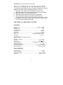
TECHNICAL SPECIFICATIONS
GENERAL
Frequency range ..........................................................................26.965-27.405 MHz
Channels ..............................................................................................................40
Modulation type ...................................................................................................AM
Antenna impedance .......................................................................................50 Ohm
Loudspeaker ...................................................................................................8 Ohm
Microphone ...............................................................................................…..Electret
Power Supply ....................................................................13.8 VDC negative ground
Size ……………………………………………………4-7/8”(W) x 6-1/2”(D) x 1-1/2”(H)
Unit Weight…………………………………………………………………….1 lb. 10 oz.
RECEIVER ( CB, 26.965-27.405 MHz )
Sensitivity at 10db S/N......................................................................................0.7 uV
Selectivity ...........................................................................................45 dB + 10 kHz
Squelch range ......................................................................................0.5 uV-500 uV
Audio output power ..................................................3.0 W @ 8 Ohm ( 10% distortion)
Distortion at 1000 mV ............................................................................................3%
Audio frequency response ........................................................................400-2400 Hz
Intermediate frequency .......................................................I ° 10.635 MHz II ° 455 kHz
Spurious response ................................................................ .............more than 45 dB
TRANSMITTER
RF Output Power ................................................................................................4.0 W
Frequency Tolerance .........................................................................................0.005%
Harmonic Suppression ..........................................................................More than 60 dB
Modulation ...........................................................................................AM 90% ( ± 5%)
9
SERVICE
If it ever becomes necessary to return your unit for service:
Pack the unit in its original box and packing, Improper packing may result in damage during
shipment. Be sure to remove the microphone from the radio before packing.
Include a full description of any problems. Include a DAY TIME telephone number in the event
we need more information.
Include a Money Order, Chashiers Check or Master Card, Visa for $ 7.50 to cover shipping and
handling.
You do not need to return accessory items (brackets, screws, power cord, antenna, etc.) unless
they may be directly related to the problem.
Include a photocopy of the bill of sale or other proof of purchase showing the date of sale. (credit
card statements are not acceptable)This information must be included before warranty service
can be considered.
A flat rate charge of 45 dollars will apply to radios not covered by the Warranty. Master Card,
Visa or Money Order will be accepted for payment only. Personal checks will not be accepted
and will delay the repair of your radio until we receive payment by approved methods.
Midland Consumer Radio inc.
Hereby certifies that this unit has
been designed, manufactured,
FCC type accepted and certified
in accordance with part 95 and
Part 15, Subpart C of the current
FCC rules and regulations as of
the date of manufacture.
10
LIMITED WARRANTY.
Midland Consumer Radio will repair or replace, at its option without charge, your 77-104XL CB
transceiver which fails due to a defect in material or workmanship within one year following the
initial consumer purchase.
This warranty does not include the cost of labor for removal or re-installation of the product in a
vehicle or other mounting.
Performance of any obligation under this warranty may be obtained by returning the warranted
product, freight prepaid, along with a readable copy of the original dated sales receipt, to
Midland Consumer Radio, Warranty Service Department 1670 North Topping, Kansas City,
Missouri 64120, or to the place of purchase (if a participating dealer).
This warranty gives you specific legal rights, and you may also have other rights which vary from
state to state.
Note:
The above warranty applies only to merchandise purchased in the United States of
America or any of the territories or possessions or from U.S. military exchange
MIDLAND
CONSUMER RADIO
1670 N. Topping
Kansas City, Mo. 64120
Phone 816-241-8500
E-mail: [email protected]
Printed in China
11