1
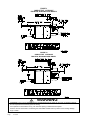
INSTALLATION INSTRUCTIONS
WALL MOUNTED GAS/ELECTRIC
Models:
W24G2-A
W24G2-B
W24G2-C
W30G2-A
W30G2-B
W30G2-C
W36G2-A
W36G2-B
W36G2-C
W42G2-A
W42G2-B
W42G2-C
W48G2-A W60G2-A
W48G2-B W60G2-B
W48G2-C W60G2-C
WARNING
READ ALL INSTRUCTIONS CAREFULLY BEFORE
BEGINNING THE INSTALLATION.
THE INSTALLATION MUST COMPLY WITH THESE
INSTRUCTIONS AND THE REQUIREMENTS OF
ALL GOVERNING CODES AND ORDINANCES FOR
THE INSTALLATION LOCATION.
IT IS THE RESPONSIBILITY OF INSTALLER
TO KNOW AND UNDERSTAND ALL OF THESE
REQUIREMENTS.
FAILURE TO DO SO COULD CREATE A HAZARD
RESULTING IN PROPERTY DAMAGE, BODILY
INJURY, OR DEATH.
Bard Manufacturing Company, Inc.
Bryan, Ohio 43506
www.bardhvac.com
Manual No.: 2100-590C
Supersedes:2100-590B
Date:2-11-15
Page
1 of 67
CONTENTS
Page
Page
Getting Other Information and Publications............... 4
W**G Series Model Nomenclature............................ 5
Ventilation Options................................................. 5
Air Conditioning Module Options.............................. 6
1. Important...................................................... 10
2. Application.................................................... 10
3. Duct Work...................................................... 10
4. High Altitude Applications............................... 11
5. Transportation Damage.................................... 11
6. Installation.................................................... 11
7. Wall Mounting................................................ 11
8. Mounting the Unit.......................................... 11
9. Clearances..................................................... 17
10.Vent Terminal and Combustion Inlet Hood......... 18
11.Optional Vertical Venting................................. 18
12.Vent Resizing Instructions............................... 19
13.Fresh Air Intake.............................................. 19
14. Condensate Drain........................................... 19
15.Wiring – Main Power....................................... 20
16.Wiring – Low Voltage Wiring............................. 21
17. Thermostats................................................... 21
18.Gas Supply & Piping....................................... 26
19.Manifold Pressure Adjustment......................... 27
0.Checking Gas Input Rate......................... 27 & 28
2
21.Standard Orifice Sizing & High
Altitude Derate............................................... 29
22.Conversion of Gas Input BTUH From High
to Low Rating................................................. 32
23.Measuring Air Temperature Rise....................... 32
24. Filters........................................................... 33
25.Compressor Control Module..................... 33 & 34
26.Lighting & Shutdown Instructions.................... 35
27.Service Agency Procedures.............................. 36
28.Maintaining Unit in Good Working Order... 36 & 37
29. Replacement Parts......................................... 37
30.Sequence of Operation – Heating..................... 38
31.Sequence of Operation – Cooling..................... 38
32.Indoor Blower Operation.................................. 39
33.Pressure Service Ports.................................... 47
34. Refrigerant Charge.......................................... 48
35.Fan Blade Setting Dimensions......................... 48
36.Low NOx Burner Assembly "N" Suffix
Models Only – U.S. Installations Only............... 48
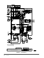
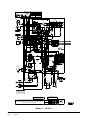
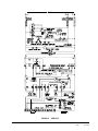
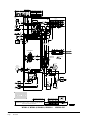
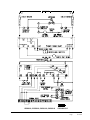
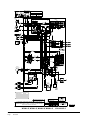
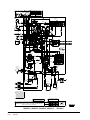
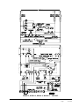
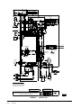
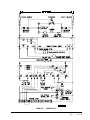
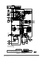
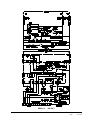
Index – Wiring Diagrams........................................ 49
Wiring Diagrams............................................50 – 67
Manual2100-590C
Page
2 of 67
CONTENTS
Page
FIGURES
Figure 1
Figure 2
Figure 2A
Figure 3
Figure 3A
Figure 4
Figure 5
Figure 6
Figure 7
Figure 8
Figure 9
Figure 10
Figure 11
Figure 12
Figure 13
Figure 14
Figure 15
Figure 16
Figure 17
Figure 18
Figure 19
Figure 20
Figure 21
Figure 22
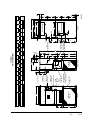
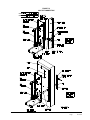
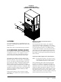
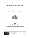
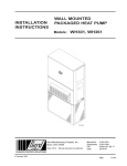
Unit Dimensions................................... 9
Mounting Instructions – W24-36G........ 12
Mounting Instructions – W42-60G........ 13
Combustible Clearance – W24-36G ...... 14
Combustible Clearance – W42-60G....... 14
Wall Mounting Instructions................... 15
Wall Mounting Instructions................... 15
Common Wall Mounting Installations..... 16
Location of Vent Terminal in Shipping... 17
Vent Terminal & Combustion
Air Intake........................................... 18
Fresh Air Damper................................ 19
Installation of Flexible Conduit............. 21
Low Voltage Wiring-No Vent Pkg............ 22
Low Voltage Wiring.............................. 23
Low Voltage Wiring-EIFM Econo............ 24
Gas Pipe Connection............................ 25
Proper Piping Practice......................... 26
Access Internal Filter through
Upper Service Door.............................. 33
Lighting & Shutdown Instruction Label.. 35
Top View of Gas Control....................... 36
Sequence of Operation – Electronic
Blower Control.................................... 38
Furnace Control Board &
Blower Control.................................... 39
Fan Blade........................................... 48
Low NOx Insert................................... 48
Page
TABLES
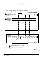
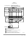
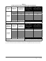
Table 1 Specifications – W24-36G Models............ 7
Table 1A Specifications – W42-60G Models............ 8
Table 2 Minimum Installation Clearances............ 17
Table 3 Thermostat Wire Size............................. 21
Table 4 Wall Thermostat.................................... 21
Table 5 Length of Standard Pipe Threads............ 26
Table 6 Gas Pipe Sizes – Natural Gas................. 26
Table 7 Natural Gas Derate Capacities
For All Models...................................... 29
Table 8 Natural Gas Orifice Tables – W24-36G.... 30
Table 8A Natural Gas Orifice Tables – W42-60G.... 31
Table 9 Motor Speed Taps................................. 39
Table 10 W24G Indoor Blower Performance.......... 40
Table 11 W30G Indoor Blower Performance.......... 41
Table 12 W36G Indoor Blower Performance.......... 42
Table 13 W42G Indoor Blower Performance ......... 43
Table 14 W48G Indoor Blower Performance.......... 44
Table 15 W60G Indoor Blower Performance.......... 45
Table 16 Integrated Furnace & Blower
Control Operation.................................. 46
Table 17A W24G2-W36G2
Cooling Pressure Table........................... 47
Table 17B W42G2-W60G2
Cooling Pressure Table........................... 47
Table 18 Fan Blade Dimension............................ 48
Manual2100-590C
Page
3 of 67
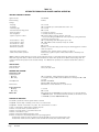
Getting Other Information and Publications
These publications can help you install the furnace.
You can usually find these at your local library or
purchase them directly from the publisher. Be sure
to consult current edition of each standard.
National Fuel Gas Code.....ANSI Z223.1 / NFPA 54
National Electrical Code............... ANSI / NFPA 70
Standard for the Installation ...... ANSI / NFPA 90A
of Air Conditioning and Ventilating Systems
Standard for Warm Air ............... ANSI / NFPA 90B
Heating and Air Conditioning Systems
Standard for Chimneys, ........................NFPA 211
Fireplaces, Vents, and Solid Fuel Burning
Appliances
Load Calculation for ......................ACCA Manual J
Residential Winter and Summer Air Conditioning
Duct Design for Residential ......... ACCA Manual D
Winter and Winter Air Conditioning and Equipment
Selection
Canadian Electrical Code......................CSA C22.1
FOR MORE INFORMATION, CONTACT THESE
PUBLISHERS:
ACCA
Air Conditioning Contractors of America
1712 New Hampshire Avenue, NW
Washington, DC 20009
Telephone: (202) 483-9370
ANSI
American National Standards Institute
11 West Street, 13th Floor
New York, NY 10036
Telephone: (212) 642-4900
Fax: (212) 302-1286
ASHRAE
American Society of Heating Refrigerating, and Air Conditioning Engineers, Inc.
1791 Tullie Circle, NE.
Atlanta, GA 30329-2305
Telephone: (404) 636-8400
Fax: (404) 321-5478
NFPA
National Fire Protection Association
Batterymarch Park
P.O. Box 9101
Quincy, MA 02269-9901
Telephone: (800) 344-3555
Fax: (617) 984-7057
CSA
Canadian Standards Association
178 Rexdale Boulevard
Rexdale, Ontario
Canada. M9W 1R3
Telephone: (416) 447-4044
Canadian Installation Code…………CAN/CGA B149
BARD MANUFACTURING COMPANY, INC.
BRYAN, OHIO 43506 USA
Manual2100-590C
Page
4 of 67
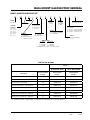
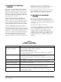
WALL MOUNT GAS/ELECTRIC GENERAL
MODEL NUMBER NOMENCLATURE
W
42 MODEL
Wall Mount
COOLING
CAPACITY
24 – 2 ton
30 – 2½ ton
36 – 3 ton
42 – 3½ ton
48 – 4 ton
60 – 5 ton
G 2 –
A
X
C
REVISION
GAS/ELECTRIC
X
EMISSIONS
X=Standard
N= NOx Certified
X
X
X
COLOR
X – Beige
(Standard)
4 – Gray
VENT
(See table
below)
VOLTAGE
A – 230/208-60-1
B – 230/208-60-3
C – 460-60-3
FEATURE
(-) – Standard
D – Dehumidification
C – Canadian Approval
X
X
CONTROL OPTIONS
(See table page 6)
COIL OPTIONS
X – Standard
1 – Phenolic coated evaporator
2 – Phenolic coated condenser
3 – Phenolic coated both coils
FILTER
X – 2" Pleated (Standard)
W – 1" Washable
OUTLET
X – Front (Standard)
T – Top
HEATING INPUT
2 - 3 Ton
3.5 - 5 Ton
A – 45,000
B – 75,000
B – 67,500
C – 100,000
C – 90,000
D – 125,000*
*125,000 BTU input model is not NOx certified.
VENTILATION OPTIONS
Models
W24G, W30G, W36G
W42G, W48G, W60G
Factory Installed
Code No.
Field Installed
Part No.
Field Installed
Part No.
Barometric Fresh Air Damper
X
WGBFAD-3
WGBFAD-5
Blank-Off Plate
B
WGBOP-3
WGBOP-5
Motorized Fresh Air Damper
M
WGMFAD-3A
WGMFAD-5A
Commercial Ventilator – Spring Return
V
WGCRVS-3A
WGCRVS-5A
Commercial Ventilator – Power Return
P
WGCRVP-3A
WGCRVP-5A
Economizer - Fully Modulating
E
WGEIFM-3C
WGEIFM-5C
Energy Recovery Ventilator – 230 Volt
R
WGERV-A3B
WGERV-A5B
Energy Recovery Ventilator – 460 Volt
R
WGERV-C3C
WGERV-C5C
Description
Low ambient control is required with economizer for low temperature compressor operation.
Manual2100-590C
Page
5 of 67
AIR CONDITIONING MODULE OPTIONS
CCM
STD
HPC
STD
LPC
STD
LAC
SK
•
•
Factory Installed
Code
Field Installed
Part
H
CMA-29
Field Only
SK111 or CMC-15
STD – Standard equipment.
CCM Compressor control module has adjustable 30 second to 5 minute delay-on-break timer. On initial power up, or any
time the power is interrupted, the delay-on-make will be 2 minutes plus 10% of the delay-on-break setting. There is no
delay-on-make during routine operation of the unit. The module also provides the lockout feature (with 1 retry) for high
and/or low pressure controls, and a 2-minute timed bypass for low pressure control.
HPC High pressure control is auto reset. Always used with compressor control module (CCM) which is included. See Note
.
LPC Low pressure control is auto reset. Always used with compressor control module (CCM) which is included. See Note .
LAC Low ambient control permits cooling operation down to 0°F. (Includes fan cycling control + Freeze Stat)
SK CMC-15 is PTCR Start Kit can be used with all -A single phase models. Increases starting torque 2-3X. Not used for -B
or -C 3-phase models. Do not use if SK111 is used.
SK
SK111 Start Capacitor and Potential Relay Start Kit can be used with all -A single phase models. Increases starting
torque 9x. Not used for -B or -C 3-phase models. Do not use if CMC-15 is used.
Manual2100-590C
Page
6 of 67
Manual2100-590C
Page
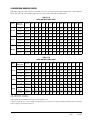
7 of 67
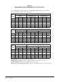
16
21
30
Minimum Circuit Ampacity
** Delay Fuse or Circuit Breaker Max.
58
64
1/4
156
2400
1.8
230/208-60-1
156
1.5
230/208-60-1
1/5
2.2
230/208-60-1
8.3
6.4/7.1
9.9/10.9
12.8
230/208-3
25
230/208-1
* 75 degree C Copper wire size
** Maximum time delay fuse or circuit breaker
Full Load Amps
Volts
Horsepower
Blower Motor
CFM
Full Load Amps
Volts
Horsepower
Fan Motor
Full Load Amps (3-motors)
Volts
Energy Recovery Ventilator
Lock Rotor Amps
Branch Circuit Selection Current
Rated Load Amps
Volts
Compressor
197-253
197-253
Operating Voltage Range
230/208-3
230/208-1
Electrical Rating - 60 Hz
W24G2-B
W24G2-A
Models
0.8
460-60-1
156
0.8
460-60-1
28
5.1
3.9
460-3
15
9
414-506
460-3
W24G2-C
1/5
2.2
230/208-60-1
71
9.0
7.5/8.2
230/208-3
25
17
197-253
230/208-3
W30G2-B
1/4
240
2400
2.2
230/208-60-1
240
1.5
230/208-60-1
77
14.1
11.8/12.9
230/208-1
35
23
197-253
230/208-1
W30G2-A
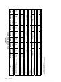
TABLE 1
SPECIFICATIONS
W24G, W30G AND W36G MODELS
1.1
460-60-1
240
0.8
460-60-1
38
5.6
4.7
460-3
15
10
414-506
460-3
W30G2-C
1/5
2.2
230/208-60-1
110
15.6
13.3/14.6
230/208-3
40
25
197-253
230/208-3
W36G2-B
1/4
246
2400
2.2
230/208-60-1
246
1.5
230/208-60-1
112
17.9
15.3/16.7
230/208-1
45
28
197-253
230/208-1
W36G2-A
1.1
460-60-1
246
0.8
460-60-1
44
6.0
5.1
460-3
15
11
414-506
460-3
W36G2-C
Manual2100-590C
Page
8 of 67
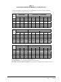
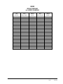
23
31
50
Minimum Circuit Ampacity
** Delay Fuse or Circuit Breaker Max.
83.1
109
1/3
156
3050
3.4
230/208-60-1
156
2.5
230/208-60-1
1/3
2.2
230/208-60-1
13.1
10.2/11.5
15.5/17.5
19.9
230/208-3
35
230/208-1
* 75 degree C Copper wire size
** Maximum time delay fuse or circuit breaker
Full Load Amps
Volts
Horsepower
Blower Motor
CFM
Full Load Amps
Volts
Horsepower
Fan Motor
Full Load Amps (3-motors)
Volts
Energy Recovery Ventilator
Lock Rotor Amps
Branch Circuit Selection Current
Rated Load Amps
Volts
Compressor
197-253
197-253
Operating Voltage Range
230/208-3
230/208-1
Electrical Rating - 60 Hz
W42G2-B
W42G2-A
Models
1.5
460-60-1
156
1.3
460-60-1
41
6.1
4.8
460-3
15
11
414-506
460-3
W42G2-C
1/3
2.2
230/208-60-1
98
14.5
13.1/14.5
230/208-3
35
25
197-253
230/208-3
W48G2-B
1/3
240
3050
3.4
230/208-60-1
240
2.5
230/208-60-1
135
21.4
19.3/21.4
230/208-1
50
34
197-253
230/208-1
W48G2-A
TABLE 1A
SPECIFICATIONS
W42G, W48G AND W60G MODELS
1.5
460-60-1
240
1.3
460-60-1
55
6.4
6.4
460-3
15
12
414-506
460-3
W48G2-C
1/3
2.2
230/208-60-1
110
15.6
12.8/14.7
230/208-3
40
28
197-253
230/208-3
W60G2-B
1/3
246
3050
3.4
230/208-60-1
246
2.5
230/208-60-1
134
26.3
21.6/24.7
230/208-1
60
40
197-253
230/208-1
W60G2-A
1.5
460-60-1
246
1.3
460-60-1
52
7.8
7.8
460-3
20
14
414-506
460-3
W60G2-C
Manual2100-590C
Page
9 of 67
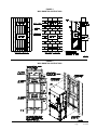
G
F
S
12 - 7 HOLES
16 - 6 HOLES
UNIT
W24G-W30G-W36G
W42G-W48G-W60G
FRONT
CONDENSER
AIR OUTLET
W
A
7.88
9.88
UNIT
W24G-W30G-W36G
W42G-W48G-W60G
U
2.88
3.88
C
13.88
15.88
N
VENT OPTION
PANEL
CIRCUIT BREAKER/
DISCONNECT ACCESS
PANEL (LOCKABLE)
CONTROL
PANEL DOOR
FILTER
SERVICE
DOOR
FRONT DOOR
COMBUSTION
AIR INTAKE
COMBUSTION
AIR EXHAUST
VESTIBULE
DOOR
V
22.9
24.9
D
24.25
27.25
4 DEG. PITCH IN TOP
3.75
T
B
27.88
29.88
P
W
38
42
RIGHT SIDE
DD
Y
4.44
8.44
CONDENSER
AIR INLETS
D
X
17.84
17.34
E
F
G
40
25.63
14.88
43.81
31.63
J
L
M
2.25
Z
H
81.63
87.5
Z
U
K
C
I
A
FF
GG
HH
AA
11.44
12.19
30
I
FIGURE 1
UNIT DIMENSIONS
H
CC
9
10
LOW VOLTAGE
ENTRANCES
HIGH VOLTAGE
ENTRANCES
GAS
ENTRANCES
3.25
BB
V
Y
AA
X
Q
II
7.25
DD
FF
GG
EE
E
1.25
B
O
HH
2
2.75
4.5
P
B
BACK
RETURN OPENING
BB
SUPPLY OPENING
1.13
CC
EE
36.25
40.25
J
K
L
M
N
O
27.38 27.5
39.25
14.12 15.44 15.31
33.38 28.75
42.88
II
0.38
0.44
2.5
Q
R
MIS-3239
T
S
S
S
S
S
R
5.88
3.75
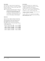
CAUTION
During the initial firing of the burners there will probably be some amount of smoke issued to the
circulating air stream as the result of residual oil burning off of the heat exchanger tubes. This oil
is required during the forming process of the stainless steel heat exchanger tubes to facilitate the
bending. OSHA or the National Toxicology Program does not list the oil as a carcinogen. In vapor
form this may be irritating to the eyes or could cause headaches. This is a one-time occurrence,
and ventilation of the space may be required depending upon the space being conditioned.
1.IMPORTANT
The equipment covered in this manual is to be installed
by trained, experienced service and installation
technicians. All duct work or portions thereof not in the
conditioned space should be properly insulated in order
to both conserve energy and prevent condensation or
moisture damage.
2. APPLICATION
This is a fan-assisted forced air gas furnace with electric
air conditioning for outdoor installation. A fan-assisted
furnace is equipped with an integral mechanical means
to draw products of combustion through the combustion
chamber and heat exchanger. The furnace installation
must conform with local building codes and ordinances
or, in their absence, with the National Fuel Gas Code
ANSI Z223.1 or CAN/CGA-B149.1, latest edition,
and the National Electrical Code ANSI/NFPA-7 or CSA
C22.1, latest edition. It is the personal responsibility
and obligation of the purchaser to contact a qualified
installer to assure that installation is adequate and is in
conformance with governing codes and ordinances.
3. DUCT WORK
The unit is designed for use with or without duct
work. See Warning on Page 10. Flanges are provided
for attaching the supply and return ducts. These
instructions explain the recommended method to install
the air cooled self-contained electric air conditioning
and gas heating unit and the electrical wiring
connections and gas piping to the unit. The refrigerant
system is completely assembled and charged. All
internal wiring is complete.
These instructions and any instructions packaged with any
separate equipment required to make up the entire heating/
cooling system should be carefully read before beginning
the installation. Note particularly “Starting Procedure” and
any tags and/or labels attached to the equipment.
All duct work, supply and return, must be properly sized
for the design airflow requirement of the equipment.
Air Conditioning Contractors of America (ACCA) is an
excellent guide to proper sizing.
Refer to Tables 10, 11, 12, 13, 14 and 15 in this Manual
for maximum static pressure available for duct design.
Manual2100-590C
Page
10 of 67
WARNING
In all cases, there must be a metal duct
connection made to the supply air flange, and
a one inch clearance to combustibles must be
maintained to this duct connection.
For free blow applications, a metal sleeve
must be used in the wall opening itself, again
maintaining a one inch clearance to combustibles.
Failure to use the sheet metal can cause fire
resulting in property damage, injury, or death.
See Figure 3 and clearance information in Section 9
and Table 2 for additional information.
Design the duct work according to methods given by
the Air Conditioning Contractors of America (ACCA).
When duct runs through unheated spaces, it should be
insulated with a minimum of one-inch of insulation.
Use insulation with a vapor barrier on the outside of the
insulation. Flexible joints should be used to connect
the duct work to the equipment in order to keep the
noise transmission to a minimum.
A one-inch clearance to combustible material for the
first three feet of duct attached to the outlet air frame
is required. See Wall Mounting Instructions and
Figures 2, 2A, 3 and 3A for further details.
Ducts through the walls must be insulated and all joints
taped or sealed to prevent air or moisture entering the wall
cavity.
Some installations may not require any return air duct.
A metallic return air grille is required with installations
not requiring a return air duct. The spacing between
louvers on the grille shall not be larger than 5/8 inch.
Any grille that meets with the 5/8 inch louver criteria
may be used. It is recommended that Bard Return Air
Grille or Return Filter Grille be installed when no return
duct is used. Contact distributor or factory for ordering
information. If using a return air filter grille, filters must be
of sufficient size to allow a maximum velocity of 400 fpm.
NOTE: If no return air duct is used, applicable
installation codes may limit this cabinet to
installation only in a single story structure.
4. HIGH ALTITUDE APPLICATIONS
8. MOUNTING THE UNIT
Ratings of gas utilization equipment are based on sea
level operation and need not be changed for operation
at elevations up to 6,000 feet. For operation at
elevations above 6,000 feet and in the absence of
specific recommendations from the local authority
having jurisdiction, equipment ratings shall be reduced
as specified in Section 21.
1. These units are secured by wall mounting brackets
which secure the unit to the outside wall surface at
both sides. A bottom mounting bracket is provided
for ease of installation but is not required.
5. TRANSPORTATION DAMAGE
All units are packed securely in shipping container.
All units should be carefully inspected upon arrival for
damage. In the event of damage, the consignee should:
1. Note on delivery receipt of any damage to
container.
2. Notify carrier promptly, and request an inspection.
3. In case of concealed damage, the carrier must be
notified as soon as possible within 15 days after
delivery.
4. Claims for any damage, apparent or concealed,
should be filed with the carrier, using the following
supporting documents:
A. Original Bill of Lading, certified copy, or
indemnity bond.
B. Original paid freight bill of indemnity in lieu
thereof.
C.
Original invoice or certified copy thereof showing
trade and other discounts or deductions.
D. Copy of the inspection report issued by
carrier’s representative at the time damage is
reported to carrier.
6.INSTALLATION
Size of unit for proposed installation should be based
on heat loss/heat gain calculations made according to
methods of Air Conditioning Contractors of America
(ACCA). The air duct should be installed in accordance
with the Standards of the National Fire Protection
Association for the Installation of Air Conditioning and
Ventilating Systems of Other Than Residence Type,
NFPA No. 90A, and Residence Type Warm Air Heating
and Air Conditioning Systems, NFPA No. 90B. Where
local regulations are at a variance with instructions,
installer should adhere to local codes.
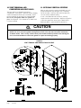
7. WALL MOUNTING INFORMATION
1. Two holes for the supply and return air openings
must be cut through the wall as detailed in Figure 4.
2. On wood-frame walls, the wall construction must
be strong and rigid enough to carry the weight of
the unit without transmitting any unit vibration.
3. Concrete block walls must be thoroughly inspected
to insure that they are capable of carrying the
weight of the installed unit.
CAUTION
If the bottom bracket is used, be certain the
bracket is secured to the outside wall surface
in a way sufficient to support the entire
weight of the unit during installation until side
mounting brackets are secured.
2. The W42G, W48G and W60G models are suitable
for 0 inch clearance on the installation mounting
wall and to the top. For all models the supply
air duct flange and the first 3 feet of supply air
duct require a minimum of 1-inch clearance to
combustible material. The W24G, W30G and
W36G models are suitable for 0 inch clearance
on the installation mounting wall, but require
1-inch clearance to the top if combustible material
overhang projects above the unit. See Figures 3
and 3A. If a combustible wall, use a minimum
of Figure 1 “A” dimension plus 2 inches and “B”
dimension plus 2 inches. See Figures 4 and 5 for
details.
WARNING
Failure to provide the one inch clearance
between the supply duct and a combustible
surface for the first three feet of duct can result
in fire causing damage, injury or death.
3. Locate and mark lag bolt locations and bottom
mounting bracket location.
4. Mount bottom mounting bracket.
5. Hook top rain flashing under back bend of top.
Top rain flashing is shipped secured to the right
side of the back.
6. Position unit in opening and secure with 5/16 lag
bolts; use 7/8 inch diameter flat washers on the
lag bolts. Use lag bolts long enough to support
the unit’s weight when mounted to the structure.
This length may be dependant on the type of
construction.
7. Secure rain flashing to wall and caulk across entire
length of top. See Figure 3.
8. On side-by-side installations, maintain a minimum
of 20 inches clearance on right side to allow
access to control panel and burner compartment,
and to allow proper airflow to the outdoor coil.
Additional clearance may be required to meet local
or national codes.
Manual2100-590C
Page
11 of 67
Manual2100-590C
Page
12 of 67
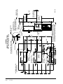
12"
29 3/4"
39 3/16"
UNIT SUPPORT
5 9/16"
Ø2 3/4" HIGH
VOLTAGE
(OPTIONAL) 2 15/16"
12"
12"
RETURN
AIR DUCT
Ø2" LOW VOLTAGE
(OPTIONAL)
Ø2 3/4" GAS
OPENING
(OPTIONAL)
12"
4 11/16"
30"
SUPPLY
AIR DUCT
4 9/16"
2"
8 5/8"
(12) FLANGE
SCREWS
29"
5 1/16"
12"
12"
4 9/16"
OUTSIDE WALL WITH
UNIT REMOVED
2 1/4"
7/16"
4 1/2"
2 15/16"
2 1/4"
FOAM AIR SEAL
TOP
27"
CONTROL
15" PANEL
28 5/16"
10"
VESTIBULE
DOOR
WALL
STRUCTURE
(OUTSIDE)
1" MIN.
RIGHT SIDE
VIEW WITH UNIT
RETURN
AIR DUCT
MIS-1681
NO CLEARANCE
NECCESSARY
SUPPLY
AIR DUCT
1" CLEARANCE ON ALL
FOUR SIDES OF SUPPLY
AIR DUCT IS REQUIRED FROM
COMBUSTABLE MATERIALS
RAIN FLASHING
SUPPLIED
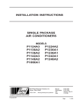
NOTE: IT IS RECOMMENDED THAT A BEAD
OF SILICONE CAULKING BE PLACED BEHIND
THE SIDE MOUNTING FLANGES AND UNDER
TOP FLASHING AT TIME OF INSTALLATION
WALL
11 5/16"
17 15/16"
18 15/16"
SEAL WITH BEAD OF CAULKING
ALONG ENTIRE LENGTH OF TOP
FIGURE 2
MOUNTING INSTRUCTIONS
FOR W24G, W30G AND W36G
Manual2100-590C
Page
13 of 67
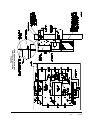
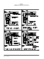
FIGURE 2A
MOUNTING INSTRUCTIONS
FOR W42G, W48G AND W60G
FIGURE 3
COMBUSTIBLE CLEARANCE
FOR W24G, W30G AND W36G MODELS
FIGURE 3A
COMBUSTIBLE CLEARANCE
FOR W42G, W48G AND W60G MODELS
WARNING
A minimum of one (1) inch clearance must be maintained between the supply air duct and combustible materials.
This is required for the first three (3) feet of ducting.
It is important to insure that the one (1) inch minimum spacing is maintained at all points.
Failure to do this could result in overheating the combustible material and may result in a fire causing damage,
injury or death.
Manual2100-590C
Page
14 of 67
FIGURE 4
WALL MOUNTING INSTRUCTIONS
FIGURE 5
WALL MOUNTING INSTRUCTIONS
Manual2100-590C
Page
15 of 67
FIGURE 6
COMMON WALL MOUNTING INSTALLATIONS
Manual2100-590C
Page
16 of 67
9.CLEARANCES
Minimum clearances, as specified in Table 2, must
be maintained from adjacent structures to provide
adequate fire protection, adequate combustion air, and
room for service personnel.
While minimum clearances are acceptable for safety
reasons, they may not allow adequate air circulation
around the unit for proper operation in the cooling
mode. Whenever possible, it is desirable to allow
additional clearance, especially around the condenser
inlet and discharge openings. DO NOT install the unit
in a location that will permit discharged air from the
condenser to recirculate to the condenser inlet.
WARNING
TABLE 2
MINIMUM INSTALLATION CLEARANCES
Outlet Duct
(from combustible materials)
1 inch first 3
feet
Vent Terminal
(from combustible materials)
* 17 inches
Condenser Inlet
20 inches
Top
See Figure 3
Burner Service
20 inches
Combustible Base (Wood or Class A,
B or C roof covering material)
0 inches
* See Figures 3 and 3A
Clearances from combustible materials
must be maintained as specified. Failure to
maintain clearances could cause fire resulting
in property damage, injury, or death.
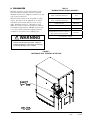
FIGURE 7
LOCATION OF VENT TERMINAL IN SHIPPING
Manual2100-590C
Page
17 of 67
10.VENT TERMINAL AND
COMBUSTION AIR INLET HOOD
The vent terminal is shipped in the burner
compartment. See Figure 7. Remove the two shipping
screws and separate the two-piece assembly. Install
the vent terminal by using the four screws provided.
Do not cut or trim gasket. Make sure gasket is in
place. See Figure 8. The combustion air intake hood
is factory installed.
11.OPTIONAL VERTICAL VENTING
With the optional vertical venting kit (VVK-5) this unit
may be vented vertically through a roof or overhang.
The kit includes a stainless steel transition drain tee,
silicone sealant, and drain tubing.
If unit is installed with vertical vent kit, annually
inspect the vent system and drain. Replace any portion
of the vent system that shows signs of deterioration.
Make sure drain is open and free of obstruction.
CAUTION
Vent terminal must be installed as shown in Figure 8 for proper operation of the heating system.
NOTE: The inner vent hood gasket is designed to stretch over and seal around the combustion
air blower outlet. This is a very critical seal to prevent water and flue products from entering the
unit. Care must be taken to insure this gasket is in place and sealing properly.
FIGURE 8
VENT TERMINAL AND COMBUSTION AIR INTAKE
Manual2100-590C
Page
18 of 67
12.VENT RESIZING INSTRUCTIONS
13.FRESH AIR INTAKE
When an existing furnace is removed from a venting
system servicing other appliances, the venting system
is likely to be too large to properly vent the remaining
attached appliances.
All units are built with fresh air inlet slots punched in
the service panel.
The following steps shall be followed with each of
the appliances remaining connected to the common
venting system, placed in operation one at a time
while the other appliances remaining connected to the
common venting system are not in operation.
1. Seal any unused openings in the venting system.
2. Inspect the venting system for proper size and
horizontal pitch, as required in the National
Fuel Gas code, ANSI Z223.1 or the CAN/CGA
B149 Installation Codes and these instructions.
Determine that there is no blockage or restriction,
leakage, corrosion and other deficiencies which
could cause an unsafe condition.
3. In so far as is practical, close all building doors
and windows and all doors between the space
in which the appliance(s) connected to the
venting system are located and other spaces of
the building. Turn on clothes dryers and any
appliances not connected to the venting system.
Turn on any exhaust fans, such as range hoods
and bathroom exhausts, so they will operate
at maximum speed. Do not operate a summer
exhaust fan. Close fireplace dampers.
4. Follow the lighting instructions. Place the
appliance being inspected in operation. Adjust
thermostat so appliance shall operate continuously.
5. Test for draft hood equipped appliance spillage at
the draft hood relief opening after 5 minutes of
main burner operation. Use the flame of a match
or candle.
If the unit is equipped with a fresh air damper
assembly, the assembly is shipped already attached
to the unit. The damper blade is locked in the
closed position. To allow the damper to operate, the
maximum and minimum blade position stops must be
installed. See Figure 9.
All capacity, efficiency and cost of operation
information as required for Department of Energy
“Energyguide” Fact Sheets is based upon the fresh
air blank-off plate in place and is recommended for
maximum energy efficiency.
The blank-off plate is available upon request from the
factory and is installed in place of the fresh air damper
shipped with each unit.
One of several other ventilation options may be
installed. Refer to model number and/or supplemental
installation instructions.
14.CONDENSATE DRAIN
A plastic drain hose extends from the drain pan at
the top of the unit down to the unit base. There are
openings in the unit base for the drain hose to pass
through. In the event the drain hose is connected to
a drain system of some type, it must be an open or
vented type system to assure proper drainage.
FIGURE 9
FRESH AIR DAMPER
6. After it has been determined that each appliance
connected to the venting system properly vents
when tested as outlined above, return doors,
windows, exhaust fans, fireplace dampers and
any other gas-burning appliances to their previous
conditions of use.
7. If improper venting is observed during any of the
above tests, the venting system must be corrected.
Manual2100-590C
Page
19 of 67
15.WIRING – MAIN POWER
WARNING
For your personal safety, turn off electric
power at service entrance panel before
making any electrical connections. Failure to
do so could result in electric shock or fire.
Refer to unit rating plate for wire sizing information and
maximum fuse or circuit breaker size. Each outdoor
unit is marked with a “Minimum Circuit Ampacity”.
This means that the field wiring used must be sized to
carry that amount of current. All models are suitable
only for connection with copper wire. Each unit and/
or wiring diagram will be marked - “Use Copper
Conductors Only”. These instructions must be adhered
to. Refer to the National Electrical Code (NEC) for
complete current carrying capacity data on the various
insulation grades of wiring material. All wiring must
conform to NEC and all local codes.
The electrical data lists fuse and wire sizes (75° C
copper) for all models.
The unit rating plate lists a “Maximum Time Delay
Relay Fuse” or circuit breaker that is to be used with
the equipment. The correct size must be used for
proper circuit protection and also to assure that there
will be no nuisance tripping due to the momentary high
starting current of the compressor motor.
The disconnect access door on this unit may be locked
to prevent unauthorized access to the disconnect. To
convert for the locking capability bend the tab located
in the bottom left hand corner of the disconnect
opening under the disconnect access panel straight
out. This tab will now line up with the slot in the door.
When shut, a padlock may be placed through the hole
in the tab preventing entry.
See “Start Up” section for important information on
three phase scroll compressor start ups.
WARNING
Failure to provide an electrical power supply
shut off means could result in electric shock
or fire.
Manual2100-590C
Page
20 of 67
Electrical Grounding
When installed, the furnace must be electrically
grounded in accordance with local codes or in the
absence of local codes, with the National Electrical
Code, ANSI/NFPA 70, or Canadian Electrical Code,
CSA22.1, latest edition. Use a copper wire from green
ground wire on the furnace to a grounded connection
in the service panel or a properly driven and electrically
grounded ground rod. See Tables 1 and 1A for proper
ground wire size.
WARNING
Failure to provide a proper electrical ground
could result in electric shock or fire.
Field Installed Equipment
Wiring to be done in the field between the furnace
and devices not attached to the furnace, or between
separate devices which are field installed and located,
shall conform with the temperature limitation for
Type T wire {63 degrees F rise (36 degrees C)} when
installed in accordance with the manufacturer’s
instructions.
Installation of Flexible Conduit Through Return Air
Opening
NOTE: To allow proper clearance between the control
panel and any vent options, 90° conduit
fittings must be used on the back of the
control panel.
Installing Conduit (See Figure 10.)
1. Remove conduit access panel if required to gain
access to area behind control panel.
2. Remove low voltage and high voltage knockouts
located in rear of control panel.
3. Run low voltage conduit through 7/8 bushing
located in conduit entrance plate and secure to low
voltage opening in rear of control panel.
4. Run high voltage conduit through 1-3/4 bushing
located in conduit entrance plate and secure to
high voltage opening in rear of control panel.
5. Replace conduit access panel if required to
complete installation.
6. Seal around conduit in conduit entrance plate.
FIGURE 10
INSTALLATION OF FLEXIBLE CONDUIT
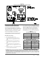
16.WIRING – LOW VOLTAGE WIRING
Low Voltage Connection
These units use a 24-volt AC low voltage circuit.
The “R” terminal is the hot terminal and the “C”
terminal is grounded.
“G” terminal is the fan input.
“Y1” terminal is the compressor input.
“R” terminal is 24 VAC hot.
“C” terminal is 24 VAC grounded.
“A” terminal is the ventilation input. This terminal
energizes any factory or field installed vent option.
“W1” terminal is the heat input.
Direct Digital Controls (DDC)
For total and proper control using DDC, a total of 5
controlled outputs are required (4 if no ventilation is
installed).
LOW VOLTAGE CONNECTIONS FOR DDC CONTROL
Fan Only
Cooling Mode
Heating Mode
Ventilation
Tap
Range
240
253 – 206
208
220 – 187
NOTE: The voltage should be measured at the field
power connection point in the unit and while
the unit is operating at full load (maximum
amperage operating condition).
460 Volt Units
All models are equipped with single primary voltage
transformers and no rewiring is required.
G
G, Y1
W1
G, A
17.THERMOSTATS
TABLE 3
THERMOSTAT WIRE SIZE
230/208 Volt Units
All models are equipped with dual primary voltage
transformers. All equipment leaves the factory wired
on 240V tap. For 208V operation, reconnect from
240V to 208V tap. The acceptable operating voltage
range for the 240V and 208V taps are:
Energize
Energize
Energize
Energize
Transformer
VA
55
FLA
2.3
Wire Gauge
20
18
16
14
12
Maximum
Distance
in Feet
gauge
gauge
gauge
gauge
gauge
45
60
100
160
250
TABLE 4
WALL THERMOSTAT
Thermostat
Predominant Features
8403-057
TH3110D1040
1 Stage Cool; 1 Stage Heat
System: heat-off-cool Fan: on-auto
Electronic Non-Programmable
8403-058
TH5220D1151
2 Stage Cool; 2 Stage Heat
Electronic Non-Programmable
HP or Conventional
Auto or Manual changeover
8403-060
1120-445
3 Stage Cool; 3 Stage Heat
Programmable/Non-Programmable Electronic
HP or Conventional
Auto or Manual changeover
Manual2100-590C
Page
21 of 67
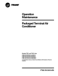
FIGURE 11
LOW VOLTAGE WIRING
Low Voltage Wiring - No Ventilation Package
Thermostat Subbase
Thermostat
Part #8403-057
TH3110D1040
C
W
Thermostat
Part #8403-060
(1120-445)
C
W1/E
A
R
W2
D/YO
C
W1
A
R
W2
E
1
2
Unit 24V
Terminal
Block
R
B
Y
G
Y2
Y1
G
O/B
Y2
Y1
G
1
RC
Y
O
L
3
2
F
Factory Installed Jumper
Unit Control Panel
1
SET SWITCH ON THERMOSTAT TO "GAS-OIL"
2
CONFIGURE THERMOSTAT FOR HEAT/COOL
MIS-2774
Manual2100-590C
Page
22 of 67
FIGURE 12
LOW VOLTAGE WIRING
Low Voltage Wiring -
MOTORIZED FRESH AIR DAMPER,
COMMERCIAL ROOM VENTILATOR-SPRING,
COMMERCIAL ROOM VENTILATOR-POWER
Thermostat Subbase
Thermostat
Part #8403-057
(TH311DD1040)
1
Thermostat
Part #8403-060
(1120-445)
2
C
W
C
W1/E
A
R
W2
D/YO
C
W1
A
R
W2
E
R
RC
B
Y
G
Y2
Y1
G
O/B
Y2
Y1
G
1
O
L
(MUST BE CONFIGURED
FOR HEAT/COOL)
Unit 24V
Terminal
Block
Y
3
2
F
5
Factory Installed
Jumper
4
3
ORANGE
RED/WHITE
BROWN/WHITE
BLUE
BLACK/WHITE
Unit Control Panel
VENT PACKAGE
WIRING PLUG
1
SET SWITCH ON THERMOSTAT TO "GAS-OIL"
2
CONFIGURE THERMOSTAT FOR HEAT/COOL
3
MUST INSTALL JUMPER FOR 8403-057 OR OTHER THERMOSTAT THAT DOES NOT
HAVE OCCUPANCY OUTPUT.
4
INSTALL IF YOU REQUIRE VENTILATION ANYTIME BLOWER IS ON.
5
CONNECT ORANGE WIRE TO "G" TERMINAL IF OCCUPENCY-BASED THERMOSTAT
OR CO2 CONTROLLER FOR DEMAND VENTILATION CONTROL IS APPLIED.
MIS-2775 A
Manual2100-590C
Page
23 of 67
FIGURE 13
LOW VOLTAGE WIRING
Low Voltage Wiring - EIFM ECONOMIZER
Thermostat
Part #8403-058
(TH5220D1151)
1
Thermostat
Part #8403-060
(1120-445)
1
Unit 24V
Terminal
Block
C
W
C
W1/E
C
W1
Thermostat Subbase
R
W2
RC
Y2
Y
G
A
R
W2
D/YO
Y2
Y1
G
O/B
A
R
W2
E
Y2
Y1
G
1
Y
L
3
2
F
Factory Installed Jumper
Unit Control Panel
WGSEIFM-5
WIRES
FROM
PLUG
BLACK
BLUE
PINK
YELLOW
PURPLE
ORANGE
RED
RED
1
Manual2100-590C
Page
24 of 67
CONFIGURE THERMOSTAT FOR HEAT/COOL
THERMISTOR
MIS-2777
FIGURE 14
GAS PIPE CONNECTION
W24G - W36G
W42G - W60G
Manual2100-590C
Page
25 of 67
18.GAS SUPPLY AND PIPING
General Recommendations
1. Be sure the gas line complies with the local codes
and ordinances, or in their absence with the
National Fuel Gas Code, ANSI Z223.1, or Natural
Gas Installation Code, CAN/CGA B149.1, or
Propane Installation Code B149.2, latest edition.
2. A sediment trap or drip leg must be installed in the
supply line to the furnace.
3. A ground joint union shall be installed in the gas
line adjacent to and upstream from the gas valve
and downstream from the manual shut off valve.
4. An 1/8” NPT plugged tapping accessible for test
gauge connection shall be installed immediately
upstream of the gas supply connection to the
furnace for the purpose of determining the supply
gas pressure. This can be omitted if local codes
permit use of plugged tapping in gas valve inlet.
5. Install listed manual shut off valve in the supply
gas line external to and immediately upstream of
the furnace. See Figure 14.
6. Use steel or wrought iron pipe and fittings.
7. DO NOT thread pipe too far. Valve distortion or
malfunction may result from excess pipe within
the control. Use pipe joint compound resistant to
the action of liquefied petroleum gases on male
threads only. DO NOT use Teflon tape. See Table
5 and Figure 15.
TABLE 5
LENGTH OF STANDARD
PIPE THREADS (INCHES)
Pipe Size
Effective Length
of Thread
Overall Length of
Thread
3/8
1/2
9/16
3/4
1/2 - - 9/16
13/16
1
9/16
1
FIGURE 15
PROPER PIPING PRACTICE
8. Refer to Table 6 for Gas Pipe Sizes for natural
gas. If more than one appliance is supplied from a
single line size, capacity must equal or exceed the
combined input to all appliances, and the branch
lines feeding the individual appliances properly
sized for each input.
THIS PRODUCT MUST BE GAS PIPED
BY A LICENSED PLUMBER OR GAS
FITTER IN THE COMMONWEALTH OF
MASSACHUSETTS.
TABLE 6
GAS PIPE SIZES – NATURAL GAS
Pipe Capacity BTU per Hour Input Pipe Size
Length
of Pipe Feet
1/2"
3/4"
10
132,000
278,000
1"
1-1/4"
520,000 1,050,000
20
92,000
190,000
350,000
730,000
30
73,000
152,000
285,000
590,000
40
63,000
130,000
245,000
500,000
50
56,000
115,000
215,000
440,000
60
50,000
105,000
195,000
400,000
70
46,000
96,000
180,000
370,000
80
43,000
90,000
170,000
350,000
100
38,000
79,000
150,000
305,000
Checking the Gas Piping
Before turning gas under pressure into piping, all
openings from which gas can escape should be closed.
Immediately after turning on gas, the system should be
checked for leaks. This can be done by watching the
1/2 cubic foot test dial and allowing 4 minutes to show
any movement, and by soaping each pipe connection
and watching for bubbles. If a leak is found, make the
necessary repairs immediately and repeat the above test.
The furnace must be isolated from the gas supply piping
system by closing the manual shut off valve on the
combination gas control valve during pressure testing
of the gas supply piping system at pressures up to 1/2
PSIG. The furnace and its individual shut off valve must
be disconnected from supply piping and supply piping
capped during any pressure testing of supply piping
system at test pressures in excess of 1/2 PSIG.
Defective pipes or fittings should be replaced and
not repaired. Never use a flame or fire in any form to
locate gas leaks; use a soap solution.
MIS-897
Manual2100-590C
Page
26 of 67
After the piping and meter have been checked
completely, purge the system of air. DO NOT bleed air
inside the furnace. Be sure to check and relight all
the gas pilots on other appliances that may have been
extinguished because of interrupted gas supply.
PROPANE (LP) GAS CONVERSION
This unit may be converted in the field for
use with Propane (LP) gas. Propane gas
conversion kit number WGCK-1 is designed
for conversions of units installed from
0 – 6,000 feet elevations. Propane gas
conversion kit number WGCK-2 is designed
for conversions of units installed from 6,001
– 10,000 feet elevations. These kits may be
purchased from your local distributor.
WARNING
When converting from propane (LP) gas to
natural gas, the gas orifice spuds and gas
valve spring must be replaced and the gas
valve regulator pressure must be adjusted
correctly. Failure to do so can result in fire,
injury or death. Refer to Tables 8 and 8A for
proper orifice sizing.
Natural gas spring kit, Part number 5603007, can be purchased through your local
distributor.
19.MANIFOLD PRESSURE
ADJUSTMENT
You will need a 0 to 15 inch water manometer with 0.1
inch resolution and a 1/8” NPT manual shut off valve
to measure actual manifold pressure.
WARNING
Correct manifold pressure is necessary for
proper ignition and burner operation. Failure
to accurately adjust pressure could cause
heat exchanger failure.
1. Turn off gas at equipment shut off valve in gas
supply line just ahead of furnace.
2. Remove plug from outlet pressure tap in gas
control or gas manifold.
3. Install 1/8” NPT manual shut off valve in hole
vacated by plug. Make sure shut off valve is in off
position.
4. Attach manometer to 1/8” NPT manual shut off
valve just installed.
5. Slowly open equipment shut off valve in gas supply
line just ahead of furnace. Start furnace following
“Operating Instructions” on front door.
6. Slowly open 1/8” NPT manual shut off valve
leading to manometer.
7. Read manifold pressure on manometer.
8. Adjust manifold pressure by turning gas control
regulator adjusting screw clockwise to increase
pressure or turning counterclockwise to decrease
pressure. Manifold pressure must be within
allowable range as follows:
•
Natural gas manifold pressure must be
between 3.2 and 3.8 inches W.C. Rated
pressure is 3.5 inches.
•
Propane gas (LP) manifold pressure must be
between 9.7 and 10.3 inches W.C. Rated
pressure is 10 inches.
NOTE: For natural gas, if gas flow rate can’t be
properly set within these pressure ranges
then you must change main burner orifices to
obtain proper gas flow rate.
9. Shut off furnace. Turn off gas at equipment shut off
valve in gas supply line just ahead of furnace. Install
outlet pressure tap plug in gas control. Turn on gas.
10.Check regulator adjustment cover screw and gas
control plug for gas leaks. Use a commercial soap
solution made for leak detection.
20.CHECKING GAS INPUT RATE
It is the installer’s responsibility to see that the
BTU input rate of the furnace is properly adjusted.
Under-firing could cause inadequate heat, excessive
condensation or ignition problems. Overfiring could
cause sooting, flame impingement or overheating of
heat exchanger.
WARNING
Failure to adjust furnace to the proper firing
rate could cause heat exchanger failure.
Depending on your local gas heating value and
elevation, you may need to adjust manifold pressure
or change orifices to get proper gas input rate. Check
with your local gas supplier to determine heating value
(BTU/cu. ft.) of natural gas in your area.
NOTE: If furnace is being installed at an altitude of
more than 6,000 feet above sea level, you
must derate the furnace. See Section 21
“Standard Orifice Sizing and High Altitude
Derate”.
Manual2100-590C
Page
27 of 67
Natural Gas Input Rate
Natural gas heating value (BTU/cu. ft.) can vary
significantly. Before starting natural gas input check,
obtain gas heating value at your location from local
supplier. You will need a stopwatch to measure actual
gas input.
9. If you left water heater, dryer or range pilots on,
allow for them in calculating correct furnace gas
input. A quick way is to allow 1,000 BTU per hour
for a water heater, 500 BTU per hour for dryer and
500 BTU per hour for each range burner pilot.
Example:
1. Gas supply pressure must be between 5 and 7
inches W.C. for natural gas.
If you left gas water heater, dryer, two range burner
pilots and one oven pilot on, allow:
2. Turn off all other gas appliances. You may leave
pilots on.
Water heater pilot
Dryer pilot
2 range burner pilots
1 range oven pilot
1,000 BTU per hour
500 BTU per hour
1,000 BTU per hour
500 BTU per hour
3,000 BTU per hour
3. Start furnace following “Operating Instructions” on
front door.
4. Let furnace warm up for 6 minutes.
5. Locate gas meter. Determine which dial has the
least cubic feet of gas and how many cubic feet
per revolution it represents. This is usually onehalf, one or two cubic feet per revolution.
6. With stopwatch, measure time it takes to consume
two cubic feet of gas.
• If dial is one-half cubic foot per revolution,
measure time for four revolutions.
• If dial is one cubic foot per revolution,
measure time for two revolutions.
• If dial is two cubic feet per revolution,
measure time for one revolution.
7. Divide this time by two. This gives average time
for one cubic foot of gas to flow through meter.
Example: If it took 58 seconds for two cubic feet
to flow, it would take 29 seconds for one cubic foot
to flow.
8. Calculate gas input using this formula:
Gas Heating Value (BTU/cu. ft.)
x 3,600 sec/hr
Gas input =
= BTU/hour
Time (Seconds for one
cubic foot of gas)
Example:
Assume it took 29 seconds for one cubic foot of
gas to flow and heating value of 1,000 BTU/cu. ft.
1,000 x 3,600
Gas input =
29
= 124,138 BTU
If you left no other pilots on, this is the furnace gas
input.
Subtracting 3,000 BTU per hour from 124,138
BTU per hour measured above equals 121,138
BTU per hour. This would be the correct furnace
gas input after allowing for pilots left on.
10. Manifold pressure may be adjusted within the
range of 3.2 inches W.C. to 3.8 inches W.C. to
get rated input ± 2 percent. See Section 19,
“Manifold Pressure Adjustment”. If you cannot
get rated input with manifold pressure within the
allowable range, you must change orifices.
Propane (LP) Gas Input Rate
WARNING
Propane (LP) gas installations do not have
gas meters to double check input rate.
Measure manifold pressure adjustment with
an accurate manometer. Failure to accurately
adjust pressure could cause heat exchanger
failure, asphyxiation, fire or explosion,
resulting in damage, injury or death.
1. Make sure you have proper main burner orifices.
2. Gas supply pressure must be between 11 and 13
inches W.C. for propane (LP) gas.
3. Start furnace following “Operating Instructions” on
front door.
4. Let furnace warm up for 6 minutes.
5. Adjust manifold pressure to 10.0 W.C. ± 0.3
inches W.C. See Section 19, “Manifold Pressure
Adjustment”.
WARNING
Do not set Propane (LP) manifold pressure
at 11.0 inches W.C. It could cause heat
exchanger failure.
Manual2100-590C
Page
28 of 67
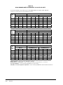
21.STANDARD ORIFICE SIZING AND
HIGH ALTITUDE DERATE
This furnace is shipped with fixed gas orifices for use
with Natural Gas and sized for 1000 BTU/cubic foot
gas. Make sure actual gas input does not exceed rating
plate input. You may need to change orifices to get
correct gas input. Whether you do or not depends on
input, and your gas heat value at standard conditions
and elevation. Consult your local gas supplier for gas
heat value and any special derating requirements. See
Section 20 for more information.
At higher altitudes, the density of the air is reduced.
Therefore, for proper combustion, the quantity of gas
burned in the furnace must also be reduced. This
is called derating. This unit must be derated when
installed at altitudes greater than 6,000 feet above
sea level. A high altitude pressure switch must also be
installed for operation above 6,000 feet. High Altitude
Pressure Switch Kit number 8620-189 is designed for
this application.
It is the installer’s responsibility to see that the
furnace input rate is adjusted properly. Derating
must be achieved by reducing the size of the main
burner orifices. Derating the furnace by adjusting the
manifold pressure lower than the range specified in
the Section 19, “Manifold Pressure Adjustment” is
considered to be an improper procedure.
Above 6,000 feet elevation orifice changes are
required, and capacity reductions are a function of
altitude impact and orifice change. Pressure switch
change is required above 6,000 feet elevation. For
Natural Gas see the Altitude Table 7 below and the
Orifice Tables 8 and 8A on following pages.
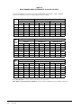
TABLE 7
NATURAL GAS DERATE CAPACITIES
FOR ALL MODELS
WG Rated
Input
Sea Level
41,000
45,000
40,500
45,000
39,204 37,908 36,612 35,640 34,992 34,182 33,696 33,048 32,643 32,076
43,560 42,120 40,680 39,600 38,880 37,980 37,440 36,720 36,270 35,640
61,000
68,000
60,750
67,500
58,806 56,862 54,918 53,460 52,488 51,273 50,544 49,572 48,965 48,114
65,340 63,180 61,020 59,400 58,320 56,970 56,160 55,080 54,405 53,460
75,000
81,000
75,000
81,000
72,600 70,200 67,800 66,000 64,800 63,300 62,400 61,200 60,450 59,400
78,408 75,816 73,224 71,280 69,984 68,364 67,392 66,096 65,286 64,152
90,000
100,000
90,000
100,000
87,120 84,240 81,360 79,200 77,760 75,960 74,880 73,440 72,540 71,280
96,800 93,600 90,400 88,000 86,400 84,400 83,200 81,600 80,600 79,200
113,000
125,000
112,500 108,900 105,300 101,700 99,000 97,200 94,950 93,600 91,800 90,675 89,100
125,000 121,000 117,000 113,000 110,000 108,000 105,500 104,000 102,000 100,750 99,000
1000
2000
3000
4000
5000
6000
7000
8000
9000
10,000
Manual2100-590C
Page
29 of 67
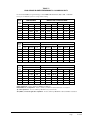
TABLE 8
NATURAL GAS ORIFICE TABLES FOR MODELS W24G, W30G AND W36G
Factory Standard
Input
Gas Heat* Value
BTU/Cu. Ft.
25000 BTU
Per Burner
Up to 6,000 Feet No
Changes Except
for BTU Content
6,001 to 8,000 Feet
Requires Pressure Switch
Change and Orifice
Change Based on BTU
Content
8,001 to 10,000 Feet
Requires Pressure Switch
Change and Orifice Change
Based on BTU Content
700-749
2.75
2.70
2.60
750-799
2.70
2.60
2.50
800-849
2.60
2.50
2.45
850-899
2.50
2.45
2.35
900-949
2.45
2.35
(2.30)
950-999
2.35
(2.30)
2.25
1000-1049**
(2.30)
2.25
[2.20]
1050-1100
2.25
[2.20]
2.15
Pressure Switch
Standard (.55)
Order 8620-189 High Altitude Pressure Switch Kit (.42)
(2.30) is the standard factory installed orifice size
[2.20] orifices are shipped with the unit for field installed
optional 10% derate
Optional
10% Field
Converted Derate
6,001 to 8,000 Feet
Requires Pressure Switch
Change and Orifice
Change Based on BTU
Content
Gas Heat* Value
BTU/Cu. Ft.
20250 BTU
Per Burner
Up to 6,000 Feet No
Changes Except
for BTU Content
8,001 to 10,000 Feet
Requires Pressure Switch
Change and Orifice Change
Based on BTU Content
700-749
2.60
2.50
2.45
750-799
2.50
2.45
2.40
800-849
2.45
2.40
(2.30)
850-899
2.40
(2.30)
2.25
900-949
(2.30)
2.25
[2.20]
950-999
2.25
[2.20]
2.15
1000-1049**
[2.20]
2.15
2.10
1050-1100
2.15
2.15
2.10
Pressure Switch
Standard (.55)
Order 8620-189 High Altitude Pressure Switch Kit (.42)
[2.20] orifices are shipped with the unit for field installed optional
(2.30) is the factory installed orifice size for full rated input
10% input rate
* At standard conditions: 30.00 inches Mercury, 60F, saturated, .60 specific gravity.
** All Natural Gas factory orifice sizing and standard input ratings based on nominal 1025 BTU/cu ft gas and sea level conditions
All other orifice sizes shown are available as individual items. See Orifice tables below for part numbers and number required.
Bard Part No.
9010-092
9010-088
9010-087
9010-086
9010-082
9010-085
9010-079
9010-084
9010-093
9010-094
9010-095
9010-096
9010-097
9010-098
Orifice Size (mm)
2.10
2.15
2.20
2.25
2.30
2.35
2.40
2.45
2.50
2.60
2.70
2.75
2.80
2.90
Manual2100-590C
Page
30 of 67
Orifice Diameter
0.0826
0.0846
0.0866
0.0885
0.0905
0.0925
0.0945
0.0964
0.0984
0.1024
0.1063
0.1082
0.1102
0.1142
No. of Orifices Required Based
on Unit Input Rating
41,000 (2)
45,000
61,000
68,000
75,000
81,000
90,000
100,000
113,000
125,000
(2)
(3)
(3)
(3)
(4)
(4)
(4)
(5)
(5)
TABLE 8A
NATURAL GAS ORIFICE TABLES FOR MODELS W42G, W48G AND W60G
Factory Standard
Input
25000 BTU
Per Burner
Gas Heat* Value
BTU/Cu. Ft.
Up to 6,000 Feet No
Changes Except
for BTU Content
6,001 to 8,000 Feet
Requires Pressure Switch
Change and Orifice
Change Based on BTU
Content
8,001 to 10,000 Feet
Requires Pressure Switch
Change and Orifice Change
Based on BTU Content
700-749
2.90
2.80
2.70
750-799
2.80
2.70
2.60
800-849
2.70
2.60
2.50
850-899
2.60
2.50
2.45
900-949
2.50
2.45
(2.40)
950-999
2.45
(2.40)
2.35
1000-1049**
(2.40)
2.35
[2.30]
1050-1100
[2.30]
2.25
2.20
Pressure Switch
Standard (.55)
Order 8620-189 High Altitude Pressure Switch Kit (.42)
(2.40) is the standard factory installed orifice size
[2.30] orifices are shipped with the unit for field installed
optional 10% derate
Optional
10% Field
Converted Derate
6,001 to 8,000 Feet
Requires Pressure Switch
Change and Orifice
Change Based on BTU
Content
22250 BTU
Per Burner
Gas Heat* Value
BTU/Cu. Ft.
Up to 6,000 Feet No
Changes Except
for BTU Content
8,001 to 10,000 Feet
Requires Pressure Switch
Change and Orifice Change
Based on BTU Content
700-749
2.75
2.70
2.60
750-799
2.70
2.60
2.50
800-849
2.60
2.50
850-899
2.50
2.45
(2.40)
900-949
(2.40)
2.35
[2.30]
950-999
2.35
[2.30]
2.25
1000-1049**
[2.30]
2.25
2.20
1050-1100
2.25
2.25
2.20
Pressure Switch
Standard (.55)
Order 8620-189 High Altitude Pressure Switch Kit (.42)
[2.30] orifices are shipped with the unit for field installed optional
(2.40) is the factory installed orifice size for full rated input
10% input rate
* At standard conditions: 30.00 inches Mercury, 60F, saturated, .60 specific gravity.
** All Natural Gas factory orifice sizing and standard input ratings based on nominal 1025 BTU/cu ft gas and sea level conditions
All other orifice sizes shown are available as individual items. See Orifice table on Page 30 for part numbers and number required.
Manual2100-590C
Page
31 of 67
22.CONVERSION OF GAS INPUT BTUH
FROM HIGH TO LOW RATING
2. Set balancing dampers in supply duct system.
All the derated WG series units are produced with
maximum BTUH input orifices installed. To field
convert input, a change to main burner orifices is
required.
4. Make sure filters are clean and in place.
NOTE: No change to air orifices is necessary. A set
of low input orifices is shipped with every
unit. They will be found packaged in a bag
behind the burner door. Refer to the unit
rating plate to confirm the proper orifice size.
Proper installation of the orifices is detailed as
follows:
A. Shut off electrical supply to the unit.
B. Shut off gas supply to the unit.
3. Check duct work for obstructions or leaks.
5. Place one thermometer in supply air plenum
approximately 2 feet from furnace. Locate
thermometer tip in center of plenum to insure
proper temperature measurement.
6. Place second thermometer in return air duct
approximately 2 feet from furnace. Locate
thermometer tip in center of duct to insure proper
temperature measurement.
7. Set room thermostat on highest temperature
setting. Operate furnace 10 minutes. Record
supply air and return air temperatures.
C. Remove burner access panel.
8. Calculate air temperature rise by subtracting return
air temperature from supply air temperature.
D. Disconnect gas valve from gas supply piping.
•
If air temperature rise is above the
temperature rise range on rating plate, furnace
is overfired or has insufficient airflow. Check
gas input following the instructions in Section, “Checking Gas Input Rate”. If air temperature
rise is still above temperature rise range
specified, more heating airflow is needed.
Check duct work and grilles to make sure all
are properly sized.
•
If air temperature rise is below the
temperature rise range on rating plate,
furnace is underfired or has too much airflow.
Check gas input following the instructions in
Section, “Checking Gas Input Rate”. If air
temperature rise is still below temperature rise
range specified, less heating airflow is needed.
Adjust dampers or grilles as needed.
•
After making adjustments, you must check
air temperature rise to verify that resulting
air temperature rise is within allowable
range. If air temperature rise is still outside
the temperature rise range specified on
rating plate, check duct system design with
a qualified heating engineer. It may be
necessary to re-size the duct work. Recheck
air temperature rise after revising duct
systems.
E. Disconnect the two wires from the gas valve.
F. Remove the manifold assembly so that orifices are now accessible and remove orifices.
G. Apply a modest amount of pipe compound to the new orifices and screw them into the manifold.
H. To assemble burner reverse steps A through G.
WARNING
Failure to follow these instructions could
create a hazard resulting in property damage,
bodily injury, or death.
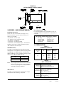
23.MEASURING AIR TEMPERATURE RISE
Air temperature rise (supply air temperature minus
return air temperature) must be within allowable air
temperature rise range specified on furnace rating
plate.
You will need two thermometers with 1° resolution
capable of reading up to 200° F. Check thermometers
to make sure they agree, or compensate accordingly.
Follow this procedure:
1. Open supply air registers and return air grilles.
Make sure the registers and grilles are free of
obstruction from rugs, carpets, drapes or furniture.
Manual2100-590C
Page
32 of 67
9. Set room thermostat to desired setting.
10.Remove thermometers and seal duct work holes.
NOTE: Failure to seal holes could result in reduced
system performance.
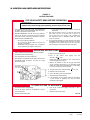
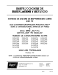
FIGURE 16
ACCESS INTERNAL FILTER
THROUGH UPPER SERVICE DOOR
FILTER
FILTER
SERVICE
DOOR
MIS-3237
24.FILTERS
A 2” thick throwaway filter is supplied with each unit.
This filter is installed by opening the filter service door.
(See Figure 16.)
Replacement filters are available through your dealer.
25.COMPRESSOR CONTROL MODULE
The compressor control module is standard on models
covered by this manual. The compressor control is
an anti-short cycle/lockout timer with high and low
pressure switch monitoring and alarm relay output.
High Pressure Switch and Lockout Sequence
(Standard Feature)
If the high pressure switch opens, the compressor
contactor will de-energize immediately. The lockout
timer will go into a soft lockout and stay in soft lockout
until the high pressure switch closes and the delayon-make time has expired. If the high pressure switch
opens again in this same operating cycle the unit will
go into manual lockout condition and the alarm circuit
will energize. Recycling the wall thermostat resets the
manual lockout.
Low Pressure Switch, Bypass and Lockout Sequence
Adjustable Delay-on-Make and Delay-onBreak Timer
On initial power up or any time power is interrupted to
the unit, the delay-on-make period begins, which will
be 2 minutes plus 10% of the delay-on-break setting.
When the delay on make is complete and the high
pressure switch (and low pressure switch, if employed)
is closed, the compressor contactor is energized. Upon
shutdown, the delay-on-break timer starts and prevents
restart until the delay-on-break and delay-on-make
periods have expired.
During routine operation of the unit with no power
interruptions the compressor will operate on demand
with no delay.
NOTE: The low pressure switch is an optional control
and the bypass and lockout sequence are part
of the standard compressor control module.
If the low pressure switch opens for more that 120
seconds, the compressor contactor will de-energize
and go into a soft lockout. Regardless the state of the
low pressure switch, the contactor will reenergize after
the delay-on-make time delay has expired. If the low
pressure switch remains open or opens again for longer
than 120 seconds the unit will go into manual lockout
condition and the alarm circuit will energize. Recycling
the wall thermostat resets the manual lockout.
Manual2100-590C
Page
33 of 67
Alarm Output
Phase Monitor
Alarm terminal is output connection for applications
where alarm signal is desired. This terminal is powered
whenever compressor is locked out due to HPC or LPC
sequences as described.
All units with three phase scroll compressors are
equipped with a three phase line monitor to prevent
compressor damage due to phase reversal.
NOTE: Both high and low pressure switch controls are
inherently automatic reset devices. The high
pressure switch and low pressure switch cut
out and cut in settings are fixed by specific
air conditioner or heat pump unit model. The
lockout features, both soft and manual, are a
function of the Compressor Control Module.
Adjustments
Adjustable Delay-on-Make and Delay-on-Break Timer
The potentiometer is used to select Delay-on-Break
time from 30 seconds to 5 minutes. Delay-onMake (DOM) timing on power-up and after power
interruptions is equal to 2 minutes plus 10% of Delayon-Break (DOB) setting:
0.5
1.0
2.0
3.0
4.0
5.0
minute
minute
minute
minute
minute
minute
(30 seconds) DOB
(60 seconds) DOB
(120 seconds)DOB
(160 seconds)DOB
(240 seconds)DOB
(300 seconds)DOB
Manual2100-590C
Page
34 of 67
= 123
= 126
= 132
= 138
= 144
= 150
second
second
second
second
second
second
DOM
DOM
DOM
DOM
DOM
DOM
The phase monitor in this unit is equipped with two
LEDs. If the “Y” signal is present at the phase monitor
and phases are correct, the green LED will light.
If phases are reversed, the red fault LED will be lit and
compressor operation is inhibited.
If a fault condition occurs, reverse two of the supply
leads to the unit. Do not reverse any of the unit factory
wires as damage may occur.
26.LIGHTING AND SHUTDOWN INSTRUCTIONS
FIGURE 17
INSTRUCTION
LABEL
BEND & PEEL
“HERE” TO REMOVE
LABEL LINER
FOR YOUR SAFETY READ BEFORE OPERATING
WARNING: If you do not follow these instructions exactly, a fire or
explosion may result causing property damage, personal injury or loss of life.
A.
This appliance does not have a pilot. It is equipped with
an ignition device which automatically lights the burner.
Do NOT try to light the burner by hand.
B.
BEFORE OPERATING smell all around the appliance
area for gas. Be sure to smell next to the floor because
some gas is heavier than air and will settle on the floor.
* If you cannot reach your gas supplier; call the fire
department.
C.
Use only your hand to push in or move the gas control
lever. Never use tools. If the lever will not push in or
turn by hand, don’t try to repair it, call a qualified service technician. Force or attempted repair may result
in a fire or explosion.
D.
Do not use this appliance if any part has been under water.
Immediately call a qualified service technician to inspect
the appliance and to replace any part of the control system and any gas control which has been under water.
WHAT TO DO IF YOU SMELL GAS
* Do not try to light any appliance.
* Do not touch any electric switch; do not use any
phone in your building.
* Immediately call your supplier from a neighbor’s
phone. Follow the gas supplier’s instructions.
OPERATING INSTRUCTIONS
1.
STOP! Read the safety information above on this label.
2.
Set the thermostat to lowest setting
3.
Turn off all electric power to the appliance.
4.
This appliance is equipped with an ignition device which
automatically lights the burner. Do NOT try to light
the burner by hand.
GAS CONTROL
KNOB SHOWN
IN “OFF” POSITION
5. Remove control access panel.
6. Push in
clockwise
gas
control
to “OFF”.
knob
slightly
and
turn
NOTE: Knob cannot be turned to “OFF” unless knob is
pushed in slightly. Do not force.
7. Wait five (5) minutes to clear out any gas. Then smell
for gas, including near the floor. If you smell gas, STOP!
Follow “B” in the safety information above on this label.
If you don’t smell gas, go to the next step.
8. Turn gas control knob counterclockwise
to “ON”.
9. Replace control access panel.
GAS
INLET
10. Turn on all electric power to the appliance.
11. Set thermostat to desired setting.
12. If the appliance will not operate, follow the instructions
“To Turn Off Gas To Appliance” and call your service
technician or gas supplier.
TO TURN OFF GAS TO APPLIANCE
1.
Set the thermostat to lowest setting.
4.
2.
Turn off all electric power to the appliance if service
is to be performed.
Push in gas control lever slightly and move to “OFF”.
Do not force.
5.
Replace control access panel.
3.
Remove control access panel.
7961-509
Manual2100-590C
Page
35 of 67
27.SERVICE AGENCY PROCEDURES
FIGURE 18
TOP VIEW OF GAS CONTROL
CAUTION
Label all wires prior to disconnection when
servicing controls. Wiring errors can cause
improper and dangerous operation. Verify
proper operation after servicing.
WARNING
Follow these procedures before inspecting
furnace.
• Turn room thermostat to its lowest or off setting.
• Turn off manual gas shut off valve.
• Wait at least 5 minutes for furnace to cool
if it was recently operating.
• Turn off furnace electrical power; failure
to do so could result in injury or death.
Main Burner
Observe the main burners in operation. The flame
should be mostly “blue” with possibly a little orange
(not yellow) at the tips of the flame. The flames
should be in the center of the heat exchanger tubes
and not impinging on the heat exchanger surfaces
themselves.
Observe the fire until the blower starts (there is a
normal delay period until the heat exchanger warms
up). There should be no change in the size or shape
of the flame. If there is any wavering or blowing of
the flame on blower start-up, it is an indication of a
possible leak in the heat exchanger.
MIS-165
Burners/Heat Exchanger/Flue Gas Passage Ways
The burners, heat exchanger and interior flue gas
passages may be inspected using a light on small
mirror or an extension handle. Remove the screws
securing the inducer and collector box. Now inspect
the upper tubes of the heat exchanger.
Check the exterior of the heat exchanger and
the interior flue gas passages for any evidence of
deterioration due to corrosion, cracking or other
causes. If signs of sooting exist, remove the burners
and clean the heat exchanger, as required.
28.MAINTAINING UNIT IN GOOD
WORKING ORDER
The unit should be inspected annually by a qualified
service agency.
WARNING
Use replacement parts listed in the
Replacement Parts list only. The use of
incorrect parts could cause improper unit
operation, resulting in damage, injury or
death.
Manual2100-590C
Page
36 of 67
WARNING
Disconnect electrical power before servicing
unit. Failure to do so could result in electrical
shock or death.
Annual Maintenance
Routine inspection and maintenance procedures are
the responsibility of the user and are outlined below.
1. Before inspecting unit:
a. Turn room thermostat to lowest or off setting.
b. Turn off equipment gas shut off valve.
c. Wait for unit to cool if it was recently
operating.
d. Turn off electrical power to unit.
2. Inspect the following:
a. Vent terminal and combustion air intake
terminal. Make sure both are free from
obstructions.
b. Vertical Vent Applications – Inspect venting
system. Make sure system has no holes, is
physically sound and free from obstructions.
c. Make sure the supply and return air flange
sleeves or duct work are securely fastened to
unit and physically sound.
d. Supply and return grilles must be open and
free from obstructions.
e. Inspect to make sure the unit is securely
fastened to the wall. Seal any possible
leaks between unit and wall with appropriate
exterior sealing material.
f. Inspect burners, heat exchanger, induced
draft blower, and induced draft blower
collector box. There must be no obvious signs
of deterioration.
g. Inspect all electrical connections and wiring.
h. Check all gas piping for leaks with soap
solution used to detect leaks.
i.
Inspect, clean, and repair as needed the
entire blower assembly, air filters, draft
inducer, cooling coils, and vent options (if
installed).
Routine Maintenance
1. Air Filters – Check the condition at least monthly
when the unit is in use, and replace as necessary.
2. Lubrication Requirements – The indoor circulating
air blower motor and outdoor circulating air fan
motor are permanently lubricated and requires
no re-oiling. The combustion air blower motor
requires no re-oiling.
WARNING
Turn off electrical power supply to prevent
injury from moving parts or electric shock.
Routine Inspection
1. Inspect the physical support of the unit annually to
make sure it is securely fastened to the building.
Also look for any obvious signs of deterioration.
2. Inspect the main burners at the beginning of each
heating season and clean as necessary.
3. Inspect the vent terminal and combustion air
intake hood for any obvious deterioration, to make
sure it is free and clear of any obstructions.
29.REPLACEMENT PARTS
WARNING
Use replacement parts listed in Replacement
Parts list. Failure to do so could cause
improper furnace operation, resulting in
property damage, personal injury, or death.
Replacement parts for the gas/electric units are
available through local distributors.
A replacement parts list manual is supplied with
each unit. When ordering parts or making inquires
pertaining to any of the units covered by these
instructions, it is very important to always supply the
complete model number and serial number of the unit.
This is necessary to assure that the correct parts (or
an approved alternate part) are issued to the service
agency.
Manual2100-590C
Page
37 of 67
30.SEQUENCE OF OPERATION –
HEATING
On a call for heat from the thermostat, the induced
draft blower is energized. Once sufficient draft is
established, the pressure switch contacts close and
the ignition system is energized. The direct spark
ignitor will be energized allowing gas to flow. At the
same time the main valve is energized, a 30-second
blower delay timer is activated.
burner orifices or incorrect manifold pressure,
insufficient combustion air, or installation deficiencies
with respect to return air duct design or sizing.
Once the problem has been resolved, reset the switch
by pressing down on the reset button on top of the
switch. See Figure 19 for additional information.
31.SEQUENCE OF OPERATION –
COOLING
After this delay, the heating speed blower relay
energizes. The blower will begin operating and
remain in operation until the set delay time after the
call for heat has been satisfied. (See Tables 10-15
for selectable blower off time delays.) This timing
sequence guarantees blower on, blower off operation.
On a call for cooling from the room thermostat, the
high speed blower relay will be energized as well as
the compressor contactor. Following termination of the
cooling cycle, the blower motor will continue to run for
one minute.
This unit is equipped with a flame roll-out switch,
which is wired in series with the control circuit. This
is a manual reset switch and is used for the purpose of
preventing possible fire hazard in the event of a system
malfunction. If this switch has opened the control
circuit, there could be a possible system malfunction.
Some of the conditions that might cause a roll-out
to occur are blockage or sooting of primary heat
exchanger, overfiring of furnace due to improper main
The unit may be equipped with a low ambient control
for lower outdoor temperature operation in the cooling
mode. If equipped with this optional control the
condenser fan will not operate immediately upon
compressor start-up, and will cycle on and off until the
condensing pressure remains above 180 PSIG. LAC
energizes the fan motor at 280 PSIG, de-energizes at
180 PSIG.
See Figure 19 for additional information.
FIGURE 19
SEQUENCE OF OPERATION
ELECTRONIC BLOWER CONTROL
Action
System Response
Thermostat calls for heat
(W terminal is energized).
•
•
•
•
•
Thermostat ends call for heat.
• Ignition system is de-energized and gas valve closes.
• Combustion air blower is de-energized after postpurge timing.
• Heat fan off delay timing begins. When timing is complete, the circulating fan is
de-energized.
Thermostat begins call for cool
(G and Y terminals re-energized).
• Cooling contactor is energized.
• Circulating fan is energized on cool speed after cool fan on delay timing.
Thermostat begins call for fan
(G terminal is de-energized).
• Circulating fan is de-energized
Limit (flame rollout) opens.
• Thermostat and ignition system are de-energized and gas valve closes.
• Combustion air blower and circulating fan heat speed are energized.
Limit (auto reset) or flame rollout
(manual reset) circuit closed.
• Combustion air blower remains energized for postpurge timing.
• The circulation fan remains energized for the selected delay off timing.
• Normal operation resumes.
Manual2100-590C
Page
38 of 67
Combustion air blower is energized.
Air proving switch makes. Airflow is established.
Ignition system is energized.
Gas valve opens and main burner lights.
Heat fan on delay timing begins. When timing is complete, the circulating fan is
energized at heat speed.
FIGURE 20
FURNACE CONTROL BOARD AND BLOWER CONTROL
32.INDOOR BLOWER OPERATION
All models have multiple speed direct drive blower
motors. If supply and return ducts are connected to the
unit, the ducts must be of adequate size. Refer to the
appropriate blower tables. See Tables 10, 11, 12, 13,
14 and 15 for maximum static pressures acceptable.
Note the minimum CFM for cooling operation.
If voltage and duct design permit, (see blower tables)
single speed operation can be achieved as follows:
Blower Motor Speed Change
1. Disconnect power supply to unit.
2. Place desired blower motor speed lead wire to
“COOL” terminal of integrated furnace control
board.
If it is desirable to have both HEAT/COOL blower motor
speed at the same speed, install a jumper wire between
“HEAT” and “COOL” terminals of the integrated
furnace control board, and place both unused motor
speed lead wires on the two “UNUSED” terminals on
the integrated furnace control board. (See Figure 20.)
TABLE 9
230 VOLT MOTOR SPEED TAPS
Speeds
3-Speed Blower Motor
Low
Red
Medium
Blue
High
Black
460 VOLT MOTOR SPEED TAPS
3. Place desired blower motor speed lead wire to
“HEAT” terminal of integrated furnace control
board.
Speeds
3-Speed Blower Motor
Low
Red
4. Place unused blower motor speed lead wire to
“UNUSED” terminal of integrated furnace control
board.
Medium
Blue
High
Black
5. Energize the system in cooling and heating modes
to check for proper blower operation.
Isolation *
Orange
Isolation *
Purple
* On 460 Volt motors, there are two motor isolation leads. The orange must connect with the black high
speed blower motor lead wire for medium and low speed blower operation. The purple wire must connect
with the blue medium speed blower motor lead wire for low speed blower operation. This is all automatically
accomplished with blower relays HSBR, MSBR and LSBR, and speed changes are all made by changes at the
integrated furnace control board.
Manual2100-590C
Page
39 of 67
TABLE 10
W24G INDOOR BLOWER PERFORMANCE @ 230 AND 460 VOLTS
Recommended W24G cooling airflow range at rated 800 CFM @ 0.15 ESP (WC) is 700 - 910 CFM
Factory set on Low Speed for cooling and High for heating.
ESP
Inches
H2O
COOLING MODE
Wet Coil
High
Medium
MANUAL FAN and HEATING MODE
90,000 BTU Input
Low
High
Medium
Low
81,000 BTU Input
High
Medium
Low
0.1
---
---
820
1260
1060
---
---
1060
870
0.2
---
950
770
1200
1010
---
1200
1010
---
0.3
---
880
700
1120
---
---
1120
940
---
0.4
---
790
---
1030
---
---
1030
860
---
0.5
910
710
---
---
---
---
950
---
---
0.6
800
---
---
---
---
---
840
---
---
ESP
Inches
H2O
COOLING MODE
Wet Coil
High
Medium
MANUAL FAN and HEATING MODE
68,000 BTU Input
Low
High
Medium
Low
61,000 BTU Input
High
Medium
Low
0.1
---
---
820
1260
1060
870
---
1060
870
0.2
---
950
770
1200
1010
---
---
1010
810
0.3
---
880
700
1120
910
---
1120
940
---
0.4
---
790
---
1030
---
---
1030
860
---
0.5
910
710
---
950
---
---
950
780
---
0.6
800
---
---
---
---
---
840
---
---
COOLING MODE
MANUAL FAN and HEATING MODE
ESP
Inches
H2O
High
Medium
Low
High
Medium
Low
High
Medium
Low
0.1
---
---
820
1260
1060
870
---
1060
870
Wet Coil
45,000 BTU Input
41,000 BTU Input
0.2
---
950
770
1200
1010
810
1200
1010
810
0.3
---
880
700
1120
910
---
1120
940
750
0.4
---
790
---
1030
860
---
1030
860
680
0.5
910
710
---
950
780
---
950
780
---
0.6
800
---
---
840
---
---
840
---
---
Voltage adjustment – Reduce airflow by 100 CFM for 208 Volt
Dehumidification coil adjustment – Reduce airflow by 35 CFM for dehumidification coil installed
Top outlet adjustment – Increase airflow by 50 CFM for top outlet models
SG-3, RG-3, non-ducted application adjustment – Reduce airflow by 100 CFM for SG-3 and RG-3 installations
Manual2100-590C
Page
40 of 67
TABLE 11
W30G INDOOR BLOWER PERFORMANCE @ 230 AND 460 VOLTS
Recommended W30G cooling airflow range at rated 1000 CFM @ 0.35 ESP (WC) is 880 - 1150 CFM
Factory set on Medium Speed for cooling and for heating.
COOLING MODE
MANUAL FAN and HEATING MODE
ESP
Inches
H2O
High
Medium
Low
High
Medium
Low
High
Medium
Low
0.1
---
---
1000
---
1260
1060
---
1260
1060
Wet Coil
90,000 BTU Input
81,000 BTU Input
0.2
---
1160
950
1370
1200
1010
---
1200
1010
0.3
---
1080
880
1290
1120
940
---
1120
940
0.4
1150
990
---
1190
1030
---
1190
1030
860
0.5
1050
910
---
1090
950
---
1090
950
---
0.6
940
---
---
980
---
---
980
840
---
COOLING MODE
MANUAL FAN and HEATING MODE
ESP
Inches
H2O
High
Medium
Low
High
Medium
Low
High
Medium
Low
0.1
---
---
1000
---
1260
1060
---
---
1060
0.2
---
1160
950
---
1200
1010
---
---
1010
0.3
---
1080
880
---
1120
940
---
1120
940
0.4
1150
990
---
1190
1030
860
---
1030
860
0.5
1050
910
---
1090
950
780
1090
950
780
0.6
940
---
---
980
840
---
980
840
660
ESP
Inches
H2O
Wet Coil
68,000 BTU Input
COOLING MODE
Wet Coil
High
MANUAL FAN and HEATING MODE
45,000 BTU Input
Medium
Low
61,000 BTU Input
High
Medium
Low
41,000 BTU Input
High
Medium
Low
0.1
---
---
1000
---
1260
1060
---
---
1060
0.2
---
1160
950
---
1200
1010
---
1200
1010
0.3
---
1080
880
1290
1120
940
---
1120
940
0.4
1150
990
---
1190
1030
860
---
1030
860
0.5
1050
910
---
1090
950
780
1090
950
780
0.6
940
---
---
980
840
660
980
840
660
Voltage adjustment – Reduce airflow by 100 CFM for 208 Volt
Dehumidification coil adjustment – Reduce airflow by 35 CFM for dehumidification coil installed
Top outlet adjustment – Increase airflow by 50 CFM for top outlet models
SG-3, RG-3, non-ducted application adjustment – Reduce airflow by 100 CFM for SG-3 and RG-3 installations
Manual2100-590C
Page
41 of 67
TABLE 12
W36G INDOOR BLOWER PERFORMANCE @ 230 AND 460 VOLTS
Recommended W36G cooling airflow range at rated 1100 CFM @ 0.250 ESP (WC) is 940 - 1250 CFM
Factory set on Medium Speed for cooling and for heating.
COOLING MODE
MANUAL FAN and HEATING MODE
ESP
Inches
H2O
High
Medium
Low
High
Medium
Low
High
Medium
Low
0.1
---
1220
1000
---
1260
1060
---
1260
1060
0.2
---
1160
950
1370
1200
1010
---
1200
1010
Wet Coil
90,000 BTU Input
81,000 BTU Input
0.3
1250
1080
---
1290
1120
940
---
1120
940
0.4
1150
990
---
1190
1030
---
1190
1030
860
0.5
1050
---
---
1090
950
---
1090
950
---
0.6
940
---
---
980
---
---
980
840
---
ESP
Inches
H2O
COOLING MODE
Wet Coil
High
MANUAL FAN and HEATING MODE
68,000 BTU Input
Medium
Low
High
Medium
Low
61,000 BTU Input
High
Medium
Low
0.1
---
1220
1000
---
1260
1060
---
---
1060
0.2
---
1160
950
---
1200
1010
---
---
1010
0.3
1250
1080
---
---
1120
940
---
1120
940
0.4
1150
990
---
1190
1030
860
---
1030
860
0.5
1050
---
---
1090
950
780
1090
950
780
0.6
940
---
---
980
840
---
980
840
660
COOLING MODE
MANUAL FAN and HEATING MODE
ESP
Inches
H2O
High
Medium
Low
High
Medium
Low
High
Medium
Low
0.1
---
1220
1000
---
1260
1060
---
---
1060
Wet Coil
45,000 BTU Input
41,000 BTU Input
0.2
---
1160
950
---
1200
1010
---
1200
1010
0.3
1250
1080
---
1290
1120
940
---
1120
940
0.4
1150
990
---
1190
1030
860
---
1030
860
0.5
1050
---
---
1090
950
780
1090
950
780
0.6
940
---
---
980
840
660
980
840
660
Voltage adjustment – Reduce airflow by 100 CFM for 208 Volt
Dehumidification coil adjustment – Reduce airflow by 35 CFM for dehumidification coil installed
Top outlet adjustment – Increase airflow by 50 CFM for top outlet models
SG-3, RG-3, non-ducted application adjustment – Reduce airflow by 100 CFM for SG-3 and RG-3 installations
Manual2100-590C
Page
42 of 67
TABLE 13
W42G INDOOR BLOWER PERFORMANCE @ 230 AND 460 VOLTS
Recommended W42G cooling airflow range at rated 1300 CFM @ .35 ESP (WC) is 1030 - 1480 CFM
Factory set on Medium Speed for heating and cooling.
COOLING MODE
MANUAL FAN and HEATING MODE
ESP
Inches
H2O
High
Medium
Low
High
Medium
Low
High
Medium
Low
0.1
---
1520
1110
---
1580
1180
---
1580
1180
Wet Coil
125,000 BTU Input
113,000 BTU Input
0.2
---
1450
1050
1880
1510
---
---
1510
1090
0.3
---
1400
---
1760
1460
---
---
1460
---
0.4
1480
1290
---
1670
1340
---
1670
1340
---
0.5
1390
---
---
1560
1240
---
1560
1240
---
0.6
1270
---
---
1430
1130
---
1430
1130
---
COOLING MODE
MANUAL FAN and HEATING MODE
ESP
Inches
H2O
High
Medium
Low
High
Medium
Low
High
Medium
Low
0.1
---
1560
1160
---
1630
1230
---
1630
1230
Wet Coil
100,000 BTU
90,000 BTU Input
0.2
---
1490
1090
---
1560
1160
---
1560
1160
0.3
---
1440
1070
1810
1510
1140
---
1510
1140
0.4
1530
1330
---
1720
1390
---
1720
1390
1020
0.5
1440
1210
---
1610
1290
---
1610
1290
970
0.6
1320
---
---
1480
1180
---
1480
1180
---
COOLING MODE
MANUAL FAN and HEATING MODE
ESP
Inches
H2O
High
Medium
Low
High
Medium
Low
High
Medium
Low
0.1
---
1600
1260
---
1680
1280
---
1680
1280
0.2
---
1530
1190
---
1610
1210
---
1610
1210
Wet Coil
75,000 BTU Input
68,000 BTU Input
0.3
---
1480
1120
1860
1560
1190
---
1560
1190
0.4
---
1360
1100
1770
1440
1070
---
1440
1070
0.5
1490
1280
---
1660
1340
970
1660
1340
970
0.6
1370
---
---
1530
1230
---
1530
1230
---
Voltage adjustment – Reduce airflow by 130 CFM for 208 Volt
Top outlet adjustment – Increase airflow by 65 CFM for top outlet models
SG-5, RG-5, non-ducted application adjustment – Reduce airflow by 170 CFM for SG-5 and RG-5 installations
Manual2100-590C
Page
43 of 67
TABLE 14
W48G INDOOR BLOWER PERFORMANCE @ 230 AND 460 VOLTS
Recommended W48G cooling airflow range at rated 1550 CFM @ .20 ESP (WC) is 1250 - 1780 CFM
Factory set on Medium Speed for cooling and Medium Speed for heating.
COOLING MODE
MANUAL FAN and HEATING MODE
ESP
Inches
H2O
High
Medium
Low
High
Medium
Low
High
Medium
Low
0.1
---
1520
---
---
1580
1180
---
1580
1180
0.2
1710
1450
---
1880
1510
---
---
1510
1110
Wet Coil
125,000 BTU Input
113,000 BTU Input
0.3
1600
1400
---
1760
1460
---
---
1460
1090
0.4
1480
1290
---
1670
1340
---
1670
1340
---
0.5
1390
---
---
1560
1240
---
1560
1240
---
0.6
1270
---
---
1430
---
---
1430
1130
---
ESP
Inches
H2O
COOLING MODE
MANUAL FAN and HEATING MODE
Wet Coil
High
Medium
100,000 BTU
Low
High
Medium
90,000 BTU Input
Low
High
Medium
Low
0.1
---
1560
---
---
1630
1230
---
1630
1230
0.2
1760
1490
---
---
1560
1160
---
1560
1160
0.3
1630
1440
---
1810
1510
1140
---
1510
1140
0.4
1530
1330
---
1720
1390
---
1720
1390
1020
0.5
1440
1210
---
1610
1290
---
1610
1290
970
0.6
1320
---
---
1480
1180
---
1480
1180
---
ESP
Inches
H2O
COOLING MODE
Wet Coil
High
Medium
MANUAL FAN and HEATING MODE
75,000 BTU Input
Low
High
Medium
Low
68,000 BTU Input
High
Medium
Low
0.1
---
1600
---
---
1680
1280
---
1680
1280
0.2
1805
1530
---
---
1610
1210
---
1610
1210
0.3
1680
1480
---
1860
1560
1190
---
1560
1190
0.4
1580
1360
---
1770
1440
1070
---
1440
1070
0.5
1490
1280
---
1660
1340
970
1660
1340
970
0.6
1370
---
---
1530
1230
---
1530
1230
---
Voltage adjustment – Reduce airflow by 130 CFM for 208 Volt
Top outlet adjustment – Increase airflow by 65 CFM for top outlet models
SG-5, RG-5, non-ducted application adjustment – Reduce airflow by 170 CFM for SG-5 and RG-5 installations
Manual2100-590C
Page
44 of 67
TABLE 15
W60G INDOOR BLOWER PERFORMANCE @ 230 AND 460 VOLTS
Recommended W60G cooling airflow range at rated 1650 CFM @ .30 ESP (WC) is 1360 - 1850 CFM
Factory set on High Speed for cooling and Medium Speed for heating.
COOLING MODE
MANUAL FAN and HEATING MODE
ESP
Inches
H2O
High
Medium
Low
High
Medium
Low
High
Medium
Low
0.1
1800
1520
---
---
1580
1180
---
1580
1180
0.2
1710
1450
---
1880
1510
---
---
1510
1110
Wet Coil
125,000 BTU Input
113,000 BTU Input
0.3
1600
1400
---
1760
1460
---
---
1460
1090
0.4
1480
---
---
1670
1340
---
1670
1340
---
0.5
1390
---
---
1560
1240
---
1560
1240
---
0.6
---
---
---
1430
---
---
1430
1130
---
ESP
Inches
H2O
COOLING MODE
MANUAL FAN and HEATING MODE
Wet Coil
High
Medium
100,000 BTU
Low
High
Medium
90,000 BTU Input
Low
High
Medium
Low
0.1
1860
1560
---
---
1630
1230
---
1630
1230
0.2
1760
1490
---
---
1560
1160
---
1560
1160
0.3
1630
1440
---
1810
1510
1140
---
1510
1140
0.4
1530
1330
---
1720
1390
---
1720
1390
1020
0.5
1440
---
---
1610
1290
---
1610
1290
970
0.6
1320
---
---
1480
1180
---
1480
1180
---
COOLING MODE
MANUAL FAN and HEATING MODE
ESP
Inches
H2O
High
Medium
Low
High
Medium
Low
High
Medium
Low
0.1
1910
1600
---
---
1680
1280
---
1680
1280
Wet Coil
75,000 BTU Input
68,000 BTU Input
0.2
1805
1530
---
---
1610
1210
---
1610
1210
0.3
1680
1480
---
1860
1560
1190
---
1560
1190
0.4
1580
1360
---
1770
1440
1070
---
1440
1070
0.5
1490
---
---
1660
1340
970
1660
1340
970
0.6
1370
---
---
1530
1230
---
1530
1230
---
Voltage adjustment – Reduce airflow by 130 CFM for 208 Volt
Top outlet adjustment – Increase airflow by 65 CFM for top outlet models
SG-5, RG-5, non-ducted application adjustment – Reduce airflow by 170 CFM for SG-5 and RG-5 installations
Manual2100-590C
Page
45 of 67
TABLE 16
INTEGRATED FURNACE AND BLOWER CONTROL OPERATION
IGNITION SEQUENCE CONTROL
Ignition Source
24 VAC DSI
Flame Sensing
Remote
Timings
-
Prepurge
Postpurge
Inter-trial purge
Pressure switch proving period
Trials for ignition
Trial for ignition
Ignition sequence lockout
-
Heat blower on - delay
Heat blower off - delay
Cool blower on - delay
Cool blower off - delay
Manual fan operations
- High limit control operation
- Flame rollout switch operation
15 seconds
30 seconds (0 if cycle terminated before valve “on”)
15 seconds
60 seconds
3 per ignition sequence
7 seconds total time to prove flame
60 minutes (after 3 trials for ignition), auto reset
- can be reset during the 60-minute lockout period by opening thermostat
circuit for 3 seconds or more
30 seconds (timing starts when ignitor cycles off)
90, 120, 150 seconds selectable; factory set at 120
7 seconds
60 seconds
Operates on selected heating speed and cycles off during ignition or burner
start-up sequence.
Automatic reset, ignition sequence restart. See Note 1.
Manual reset, igniton sequence initiated after switch is manually reset.
See Note 1.
NOTE 1: After the fourth limit trip on a given call for heat there will be a 1-hour delay before the ignition sequence will restart.
After either high limit switch or flame rollout switch actuation the inducer will operate for the 30-second post purge and the
comfort air blower will operate for the selected off delay. If on Manual Fan operation, the comfort air blower will continue to
operate.
SAFETY UNITS
High limit/Rollout
Pressure switch
SPST in 24 Volt
SPST, safe start check
COMFORT FAN CONTROL
Heating Speed Fan
Normal operation
- ON delay
- OFF delay
Flame Sense
30 seconds fixed. Timing starts when igniter de-energized.
3 selectable timings -120 seconds standard can be changed to 90 or 150
seconds.
ON when limit OPEN
OFF after OFF delay when limit CLOSES
ON if flame is sensed and there is no call for heat.
Cooling Speed Fan
- ON delay
- OFF delay
7 seconds
60 seconds
Limit Operation
Manual Fan
ON continuously on HEATING speed. When call for cool, the fan switches
to COOLING speed. Then when thermostat satisfied, the fan switches back
to HEATING speed after COOLING OFF delay.
DIAGNOSTIC INDICATOR
A red LED is provided to indicate system faults as follows:
Steady ON - Control okay in standby, call for heat, cool or fan modes
Steady OFF - Internal control fault or no power. Also check 3A fuse on control.
1 flash - Lockout due to failed ignition or flame dropouts
2 flashes - Pressure switch open with inducer on
3 flashes - Pressure switch is closed with inducer off
4 flashes - Limit switch is open
5 flashes - Flame detected with gas valve closed
6 flashes - Compressor output delayed from short cycle/staging timer
The flash rate is 0.25 seconds on, 0.25 seconds off with 2.0 seconds pause between flash codes.
The flash rate is 0.25 seonds on, 0.25 seconds off with 2.0 seconds pause between flash codes.
Manual2100-590C
Page
46 of 67
33.PRESSURE SERVICE PORTS
High and low pressure service ports are installed on all units so that the system operating pressures can be observed.
Tables 17A and 17B outline expected pressures at various indoor and outdoor temperatures.
TABLE 17A
COOLING PRESSURE TABLE
Model
W24G2
W30G2
W36G2
Return Air
Temperature
Pressure
60°
65°
70°
75°
80°
85°
90°
95°
100°
75° DB
62° WB
Low Side
High Side
105
227
108
250
111
273
115
296
118
319
121
342
124
364
127
387
129
415
131
442
134
469
136
497
138
524
140
552
80° DB
67° WB
Low Side
High Side
120
235
123
258
126
282
129
305
131
329
134
352
137
376
140
401
142
427
145
456
147
484
149
512
152
540
155
569
85° DB
72° WB
Low Side
High Side
133
245
136
268
139
292
141
316
144
340
147
363
150
387
153
411
156
440
158
469
161
498
164
527
166
556
169
585
75° DB
62° WB
Low Side
High Side
110
238
113
262
116
287
119
311
122
335
125
359
128
383
131
407
133
435
134
463
136
491
138
519
139
547
141
575
80° DB
67° WB
Low Side
High Side
126
246
129
271
131
296
134
321
137
345
139
370
142
395
145
411
146
449
148
477
150
506
152
535
154
564
156
592
85° DB
72° WB
Low Side
High Side
139
257
142
282
145
307
147
332
150
357
153
382
155
407
158
432
160
461
162
491
164
521
166
550
168
580
170
609
75° DB
62° WB
Low Side
High Side
112
256
115
280
117
304
120
328
123
352
125
377
128
401
131
425
132
452
133
480
135
508
136
536
138
563
139
591
80° DB
67° WB
Low Side
High Side
128
265
130
290
132
314
135
339
137
364
139
388
140
413
140
423
143
466
147
495
149
524
150
552
152
581
153
610
85° DB
72° WB
Low Side
High Side
141
276
144
301
146
326
148
351
150
376
153
400
155
425
157
450
159
480
161
509
162
539
164
568
166
597
168
627
105° 110° 115° 120°
105° 110° 115° 120°
125°
TABLE 17B
COOLING PRESSURE TABLE
Model
W42G2
W48G2
W60G2
Return Air
Temperature
Pressure
60°
65°
70°
75°
80°
85°
90°
95°
100°
75° DB
62° WB
Low Side
High Side
107
231
109
254
112
277
115
299
118
322
121
345
123
368
126
391
128
417
130
444
132
470
133
497
135
523
137
550
80° DB
67° WB
Low Side
High Side
122
239
124
262
127
286
129
309
132
333
134
356
137
380
139
403
141
430
143
458
145
485
147
512
149
539
151
567
85° DB
72° WB
Low Side
High Side
134
249
137
272
139
296
142
320
144
343
147
367
149
391
152
415
154
443
156
471
159
499
161
527
163
555
165
583
75° DB
62° WB
Low Side
High Side
104
241
107
264
110
287
113
311
116
334
119
358
122
381
125
404
126
433
128
462
130
490
132
519
133
548
135
576
80° DB
67° WB
Low Side
High Side
118
249
121
273
124
297
126
321
129
345
132
369
135
393
140
425
140
446
141
476
143
505
145
535
147
565
149
594
85° DB
72° WB
Low Side
High Side
131
259
133
283
136
308
139
332
142
356
144
381
147
404
150
429
152
459
154
489
156
520
159
550
161
581
163
611
75° DB
62° WB
Low Side
High Side
108
241
111
267
114
292
116
318
119
343
122
369
125
394
127
420
129
447
130
475
132
503
133
531
135
559
137
587
80° DB
67° WB
Low Side
High Side
123
249
126
275
128
302
131
328
133
354
136
380
138
406
142
422
142
461
144
490
145
519
147
548
149
576
151
605
85° DB
72° WB
Low Side
High Side
136
260
139
286
141
313
144
339
146
366
149
392
151
418
154
445
155
474
157
504
159
534
161
563
163
593
164
622
125°
Low side pressure ± 4 PSIG
High side pressure ±10 PSIG
Tables based upon rated CFM (airflow) across the evaporator coil.
If there is any doubt as to correct operating charge being in the system, the charge should be reclaimed, system evacuated
and recharged to serial plate instruction.
Manual2100-590C
Page
47 of 67
34.R-410A REFRIGERANT CHARGE
This unit was charged at the factory with the quantity
of refrigerant listed on the serial plate. AHRI capacity
and efficiency ratings were determined by testing with
this refrigerant charge quantity.
The following pressure tables show nominal
pressures for the units. Since many installation
specific situations can affect the pressure readings,
this information should only be used by certified
technicians as a guide for evaluating proper system
performance. They shall not be used to adjust charge.
If charge is in doubt, reclaim, evacuate and recharge
the unit to the serial plate charge.
35.FAN BLADE SETTING DIMENSIONS
Shown in Figure 21 is the correct fan blade setting
dimension for proper air delivery across the outdoor
coil.
36.LOW-NOX BURNER ASSEMBLY “N”
SUFFIX MODELS ONLY –
U.S. INSTALLATIONS ONLY
Natural Gas Models Only
Model numbers designated with an “N” are designed
for low NOx emissions which comply with all California
Air Quality Management District regulations for
nitrogen oxide emission levels. Refer to Figure 22 for
NOx insert information.
* * IMPORTANT * *
For propane (LP) conversions the NOx
reduction screen inserts shown below must be
removed. This is accomplished by removing
the burner box assembly and removing the
NOx screens. Reassemble unit properly
before firing. Failure to remove the NOx
screens can result in improper operation and
malfunction of the burner system.
FIGURE 21
FAN BLADE
FIGURE 22
LOW NOX INSERT
AIRFLOW
"A"
MIS-1724
TABLE 18
FAN BLADE DIMENSION
Model
Dimension A
W24G
1.25
W30G
1.25
W36G
1.25
W42G
1.75
W48G
1.75
W60G
1.75
Manual2100-590C
Page
48 of 67
INDEX
WIRING DIAGRAMS
and LADDER DIAGRAMS
Unit
Model No.
Basic
Wiring Diagram
Manual
Page No.
Basic
Ladder Diagram
Manual
Page No.
W24G2-A
4085-159B
50
4085-160
51
W24G2-B
4085-257B
52
4085-258
53
W24G2-C
4085-380B
54
4085-381
55
W30G2-A
4085-161B
56
4085-162
57
W30G2-B
4085-259B
58
4085-260
59
W30G2-C
4085-382B
60
4085-383
61
W36G2-A
4085-161B
56
4085-162
57
W36G2-B
4085-259B
58
4085-260
59
W36G2-C
4085-382B
60
4085-383
61
W42G2-A
4085-161B
56
4085-162
57
W42G2-B
4085-259B
58
4085-260
59
W42G2-C
4085-382B
60
4085-383
61
W48G2-A
4085-161B
56
4085-162
57
W48G2-B
4085-259B
58
4085-260
59
W48G2-C
4085-382B
60
4085-383
61
W60G2-A
4085-163B
62
4085-164
63
W60G2-B
4085-261B
64
4085-262
65
W60G2-C
4085-384B
66
4085-385
67
Manual2100-590C
Page
49 of 67
Freeze (ODT) Indoor Fan
Capacitor
thermostat
Evaporator Section
Black
Black
RED
INTEGRATED FURNACE CONTROL 13
LOW
VOLTAGE
STRIP 11
BLUE
32
34
BROWN
64
YELLOW
32
YELLOW
A
32
BLACK
BLUE
RED
BLACK
32
HIGH
MEDIUM
LOW
YELLOW
PRIMARY
LIMIT
RED
BLOWER SPEED COLOR CODE
Indoor
Fan Motor
Brown
Brown
RED/WHITE
A
32
RED
32
ORANGE
FUSE
PINK
FLAME
ROLLOUT
10 11 12
7 8 9
4 5 6
1 2 3
SPARK IGNITOR
120
150
BLUE
BLACK
RED
32
32
39
38
RED
42
MOVE RED WIRE TO
208V TAP FOR 208V
OPERATION
208V
C
BLACK
COM
L1
20
YELLOW/RED
BLACK/WHITE
RED
PL1
1
T2
RED
BLACK
37
PINK
36
YELLOW
32
TERM. BLOCK
(OPT.)
1
BLACK
YELLOW
2
LPC LPC
BLACK
C
Y
3
32
FAN
A
MINUTES
4
5
CC
ALR
R
HPC
RED/WHITE
YELLOW
44
A
35
16 COMPRESSOR
CONTROL
MODULE
LOW AMBIENT
CONTROL (OPT.)
Compressor
RED
RED
C
BLUE
BLUE
HIGH
PRESSURE
SWITCH
23 CAPACITOR
35
40
2
BR
T1
40
L2
15 GROUND TERMINAL
COMPRESSOR
CONTACTOR
L2
39
BLACK/WHITE
32
35
35
43
38
RED
240V
208/230-60-1
CIRCUIT 21
BREAKER
RM
HE
R
BLACK
BROWN
BLACK/WHITE
18
32
32
INDUCED
DRAFT BLOWER
L1
RED
TRANSFORMER
C
PURPLE
YELLOW
PURPLE
RED/WHITE
MV
GAS
VALVE
32
MV
NO
BLUE
32
BLACK
C
BLUE
PRESSURE
SWITCH
35
59
BLACK
FLAME SENSOR
135
P3
SPEED
37
BLACK/WHITE
GRAY
R
S
OUTDOOR
FAN
MOTOR
LOW
PRESSURE
SWITCH
Model C. Breaker Capacitor
W24G2-A
30A
40+5/440
USE COPPER CONDUCTORS
SUITABLE FOR AT LEAST 75° C
IF ANY ORIGINAL WIRE AS SUPPLIED WITH THE APPLIANCE MUST BE
REPLACED, IT MUST BE REPLACED WITH WIRING MATERIAL HAVING A
TEMPERATURE RATING OF AT LEAST 105° C EXCEPT THE IGNITION CABLE
WHICH IS 250°C HIGH VOLTAGE CABLE
W24G2-A
Manual2100-590C
Page
50 of 67
99
Wire Identification numbers
for Bard use only.
Factory Field Optional
High Voltage
Low Voltage
230/208-60-1
A
WIRES CONNECT
IF OPTION
NOT USED
4085-159 B
W24G2-A
230/208-60-1
Manual2100-590C
Page
51 of 67
Freeze (ODT) Indoor Fan
Thermostat
Capacitor
Black
Evaporator Section
Black
HIGH
MEDIUM
LOW
RED
BLACK
BLUE
32
LOW
VOLTAGE
STRIP 11
32
34
BROWN
64
YELLOW
YELLOW
A
32
BLACK
BLUE
RED
INTEGRATED FURNACE CONTROL 13
YELLOW
PRIMARY
LIMIT
RED
BLOWER SPEED COLOR CODE
Indoor
Fan Motor
Brown
Brown
A
RED/WHITE
32
32
RED
32
ORANGE
FUSE
PINK
FLAME
ROLLOUT
10 11 12
7 8 9
4 5 6
1 2 3
SPARK IGNITOR
135
150
BLUE
BLACK
RED
BLACK
32
PURPLE
PURPLE
39
32
41
38
32
L1 L2
42
BLACK
RED
RED/WHITE
BLACK/WHITE
MV
GAS
VALVE
MV
NO
BLUE
32
L3
RED
43
YELLOW
32
32
35
C
BLACK/WHITE
BLACK
L1 L2 L3
BLACK/WHITE
37
YELLOW/RED
BLACK/WHITE
PL1
BLACK
1
16 COMPRESSOR
BLACK
RED
3
LPC LPC
Y
27
TERM. BLOCK
(OPT.)
2
C
A
MINUTES
4
5
ALR
CC
HPC
R
32
31
A
35
RED/WHITE
YELLOW/BLACK
30
YELLOW
23 CAPACITOR
44
YELLOW
1
36
CONTROL
MODULE
LOW AMBIENT
CONTROL (OPT.)
Compressor
RED
RED
BLUE
BLUE
HIGH
PRESSURE
SWITCH
35
YELLOW
YELLOW
PINK
28
BLACK
T1 T2 T3
RED
25
20
18
BLACK
PHASE MONITOR
COMPRESSOR
CONTACTOR
39
TRANSFORMER
40
29
35
MOVE RED WIRE TO
208V TAP FOR 208V
OPERATION
COM
40
2
BR
RED
38
RED
240V
208V
INDUCED
DRAFT BLOWER
27
BROWN
R
GROUND TERMINAL
15
YELLOW/BLACK
32
32
208/230-60-3
CIRCUIT 21
BREAKER
YELLOW
C
BLUE
PRESSURE
SWITCH
35
59
BLACK
FLAME SENSOR
120
P3
SPEED
37
BLACK/WHITE
GRAY
T2
T1
T3
OUTDOOR
FAN
MOTOR
LOW
PRESSURE
SWITCH
Model C. Breaker Fan Capacitor
W24G2-B
25A
5/370
USE COPPER CONDUCTORS
SUITABLE FOR AT LEAST 75° C
IF ANY ORIGINAL WIRE AS SUPPLIED WITH THE APPLIANCE MUST BE
REPLACED, IT MUST BE REPLACED WITH WIRING MATERIAL HAVING A
TEMPERATURE RATING OF AT LEAST 105° C EXCEPT THE IGNITION CABLE
WHICH IS 250°C HIGH VOLTAGE CABLE
W24G2-B
Manual2100-590C
Page
52 of 67
99
Wire Identification numbers
for Bard use only.
Factory Field Optional
High Voltage
Low Voltage
230/208-60-3
A
WIRES CONNECT
IF OPTION
NOT USED
4085-257 B
W24G2-B
230/208-60-3
Manual2100-590C
Page
53 of 67
Evaporator Section
Freeze (ODT) Indoor Fan
Thermostat
Capacitor
Black
Black
YELLOW
RED
BLACK
32
RED
INTEGRATED FURNACE CONTROL 13
BLUE
ORANGE
PURPLE
Black
PRIMARY
LIMIT
BLOWER SPEED COLOR CODE
HIGH
BLACK
MEDIUM
BLUE
LOW
RED
AUX
PURPLE/ORANGE
Indoor
Fan
Motor
Brown
Brown
34
32
32
A
32
LOW
VOLTAGE
STRIP 11
BROWN
64
YELLOW
A
RED/WHITE
YELLOW
32
RED
32
ORANGE
FUSE
10 11 12
7 8 9
4 5 6
1 2 3
BLUE
2
57
54
YELLOW
YELLOW/BLACK
R
460V
32
35
C
COM
32
27
RED
38
RED
35
L1 L2 L3
BLACK
COMPRESSOR
CONTACTOR
39
20
BLACK
T1 T2 T3
35
RED
31
PINK
36
37
YELLOW/RED
A
27
BLACK
1
16 COMPRESSOR
BLACK
RED
LPC LPC
Y
3
32
TERM. BLOCK
(OPT.)
2
C
A
MINUTES
4
5
CC
ALR
R
HPC
RED/WHITE
YELLOW/BLACK
23 CAPACITOR
44
YELLOW
PL1
40 BLACK
BLACK/WHITE
3
YELLOW
YELLOW
INDUCED DRAFT 45
BLOWER RELAY
1
30
YELLOW
2
2
28
BROWN
BLACK/WHITE
4
1
57
BROWN/WHITE
35
CONTROL
MODULE
LOW AMBIENT
CONTROL (OPT.)
Compressor
RED
RED
BLUE
BLUE
HIGH
PRESSURE
SWITCH
29
BLACK/WHITE
40
PHASE MONITOR
25
48
56
BR
GROUND TERMINAL
15
RED
18 TRANSFORMER
32
32
DISCONNECT 21
YELLOW
RED
45
460-60-3
BLACK
3
LOW SPEED
BLOWER
RELAY
57
43
55
49
L2
L3
42
RED
2
RED/WHITE
BLACK/WHITE
3
PURPLE
1
L1
41
3
1
6
48
RED
54
2
32
48
53
BLACK
MED. SPEED 45
BLOWER RELAY
HIGH
SPEED
BLOWER
RELAY 46
32
4
PURPLE
MV
120
55
32
PURPLE
INDUCED
DRAFT BLOWER
58
57
37
50
32
5
GAS
VALVE
MV
NO
BLUE
35
47
1
C
BLUE
PRESSURE
SWITCH
150
SPEED
59
BLACK
FLAME SENSOR
135
P3
28
BLACK/WHITE
BLACK/WHITE
GRAY
SPARK IGNITOR
PINK
FLAME
ROLLOUT
T2
T1
T3
OUTDOOR
FAN
MOTOR
LOW
PRESSURE
SWITCH
Model Fan Capacitor
W24G2-C
5/370
USE COPPER CONDUCTORS
SUITABLE FOR AT LEAST 75° C
IF ANY ORIGINAL WIRE AS SUPPLIED WITH THE APPLIANCE MUST BE
REPLACED, IT MUST BE REPLACED WITH WIRING MATERIAL HAVING A
TEMPERATURE RATING OF AT LEAST 105° C EXCEPT THE IGNITION CABLE
WHICH IS 250°C HIGH VOLTAGE CABLE
W24G2-C
Manual2100-590C
Page
54 of 67
99
Wire Identification numbers
for Bard use only.
Factory Field Optional
High Voltage
Low Voltage
460-60-3
A
WIRES CONNECT
IF OPTION
NOT USED
4085-380 B
W24G2-C
460-60-3
Manual2100-590C
Page
55 of 67
Freeze (ODT)
Thermostat
Indoor Fan
Capacitor
BLACK
Evaporator Section
BLACK
BLOWER SPEED COLOR CODE
Indoor
Fan Motor
Brown
Brown
BLACK
BLUE
RED
INTEGRATED FURNACE CONTROL 13
BLACK
YELLOW
PRIMARY
LIMIT
HIGH
MEDIUM
LOW
RED
BLUE
32
BROWN
64
YELLOW
32
RED
34
32
A
32
LOW
VOLTAGE
STRIP 11
A
RED/WHITE
YELLOW
32
RED
32
ORANGE
FUSE
PINK
FLAME
ROLLOUT
10 11 12
7 8 9
4 5 6
1 2 3
SPARK IGNITOR
120
150
RED
BLACK
32
32
39
38
RED
42
MOVE RED WIRE TO
208V TAP FOR 208V
OPERATION
C
BLACK
L1
20
T1
YELLOW/RED
BLACK/WHITE
RED
PL1
23 CAPACITOR
RED
BLACK
PINK
36
37
YELLOW
A
1
BLACK
YELLOW
BLACK
LPC LPC
3
16 COMPRESSOR
RED
32
TERM. BLOCK
(OPT.)
2
C
Y
HPC
R
32
FAN
A
MINUTES
4
5
CC
ALR
35
RED/WHITE
YELLOW
44
YELLOW
1
40
2
T2
35
40
15 GROUND TERMINAL
COMPRESSOR
CONTACTOR
L2
39
BLACK/WHITE
COM
L2
RM
HE
208V
35
43
38
RED
240V
208/230-60-1
CIRCUIT 21
BREAKER
C
R
BLACK
BROWN
BLACK/WHITE
18
32
35
CONTROL
MODULE
B
LOW AMBIENT
CONTROL (OPT.)
Compressor
RED
RED
C
BLUE
BLUE
HIGH
PRESSURE
SWITCH
L1
RED
TRANSFORMER
32
32
BR
BLACK/WHITE
PURPLE
RED/WHITE
MV
PURPLE
INDUCED
DRAFT BLOWER
52
32
MV
NO
BLUE
32
BLACK
C
BLUE
PRESSURE
SWITCH
GAS
VALVE
59
BLACK
FLAME SENSOR
135
P3
SPEED
37
35
BLUE
GRAY
R
S
OUTDOOR
FAN
MOTOR
LOW
PRESSURE
SWITCH
Model C. Breaker
W30G2-A
30A
W36G2-A
35A
W42G2-A
50A
W48G2-A
50A
Capacitor
45+5/370
45+5/370
45+10/370
70+10/370
A
USE COPPER CONDUCTORS
SUITABLE FOR AT LEAST 75° C
IF ANY ORIGINAL WIRE AS SUPPLIED WITH THE APPLIANCE MUST BE
REPLACED, IT MUST BE REPLACED WITH WIRING MATERIAL HAVING A
TEMPERATURE RATING OF AT LEAST 105° C EXCEPT THE IGNITION CABLE
WHICH IS 250°C HIGH VOLTAGE CABLE
WIRES CONNECT
Wire Identification numbers
IF OPTION
99
for Bard use only.
NOT USED
Factory Field Optional
High Voltage
Low Voltage
W30G2-A, W36G2-A, W42G2-A, W48G2-A
Manual2100-590C
Page
56 of 67
B
WIRE NOT APPLICABLE
TO ALL MODELS
230/208-60-1
4085-161 B
W30G2-A, W36G2-A, W42G2-A, W48G2-A
230/208-60-1
Manual2100-590C
Page
57 of 67
Freeze (ODT) Indoor Fan
Thermostat
Capacitor
Black
Evaporator Section
Black
BLACK
BLACK
BLUE
RED
INTEGRATED FURNACE CONTROL 13
BLUE
RED
32
34
LOW
VOLTAGE
STRIP 11
32
A
32
HIGH
MEDIUM
LOW
YELLOW
PRIMARY
LIMIT
RED
BLOWER SPEED COLOR CODE
Indoor
Fan Motor
Brown
Brown
32
BROWN
64
YELLOW
A
RED/WHITE
YELLOW
32
RED
32
ORANGE
FUSE
PINK
FLAME
ROLLOUT
10 11 12
7 8 9
4 5 6
1 2 3
BLACK/WHITE
BLACK
120
150
BLACK
32
PURPLE
PURPLE
39
32
38
32
BLACK
RED
RED/WHITE
BLACK/WHITE
MV
GAS
VALVE
32
MV
NO
BLUE
52
41
L1
42
L2
L3
RED
43
208/230-60-3
CIRCUIT 21
BREAKER
YELLOW
C
BLUE
PRESSURE
SWITCH
37
35
59
BLACK
FLAME SENSOR
135
P3
SPEED
RED
SPARK IGNITOR
BLUE
GRAY
GROUND TERMINAL
15
YELLOW
32
YELLOW/BLACK
27
PHASE MONITOR
25
R
BLACK/WHITE
C
L1 L2 L3
20
BLACK/WHITE
18
35
PINK
37
YELLOW/RED
BLACK/WHITE
PL1
RED
BLACK
1
YELLOW
BLACK
RED
16 COMPRESSOR
RED
3
TERM. BLOCK
(OPT.)
BLACK
LPC LPC
Y
27
31
23 CAPACITOR
44
2
C
A
MINUTES
4
5
ALR
CC
HPC
R
32
30
YELLOW
A
35
RED/WHITE
YELLOW/BLACK
28
BLACK
T1 T2 T3
YELLOW
YELLOW
36
CONTROL
MODULE
B
LOW AMBIENT
CONTROL (OPT.)
Compressor
RED
RED
BLUE
BLUE
HIGH
PRESSURE
SWITCH
COMPRESSOR
CONTACTOR
39
TRANSFORMER
40
2
BR
BLACK
COM
40
1
INDUCED
DRAFT BLOWER
35
MOVE RED WIRE TO
208V TAP FOR 208V
OPERATION
208V
32
35
38
RED
240V
RED
BROWN
32
32
29
T2
T1
T3
OUTDOOR
FAN
MOTOR
LOW
PRESSURE
SWITCH
Model C. Breaker Fan Capacitor
W30G2-B
25A
5/370
W36G2-B
35A
5/370
W42G2-B
35A
10/370
W48G2-B
35A
10/370
A
USE COPPER CONDUCTORS
SUITABLE FOR AT LEAST 75° C
IF ANY ORIGINAL WIRE AS SUPPLIED WITH THE APPLIANCE MUST BE
REPLACED, IT MUST BE REPLACED WITH WIRING MATERIAL HAVING A
TEMPERATURE RATING OF AT LEAST 105° C EXCEPT THE IGNITION CABLE
WHICH IS 250°C HIGH VOLTAGE CABLE
99
Wire Identification numbers
for Bard use only.
Factory Field Optional
High Voltage
Low Voltage
W30G2-B, W36G2-B, W42G2-B, W48G2-B
Manual2100-590C
Page
58 of 67
WIRES CONNECT
IF OPTION
NOT USED
B
WIRE NOT APPLICABLE
TO ALL MODELS
230/208-60-3
4085-259 B
W30G2-B, W36G2-B, W42G2-B, W48G2-B
230/208-60-3
Manual2100-590C
Page
59 of 67
Freeze (ODT) Indoor Fan
Thermostat
Capacitor
Evaporator Section
Brown
Brown
Black Black
BLACK
YELLOW
RED
32
INTEGRATED FURNACE CONTROL 13
BLUE
ORANGE
PURPLE
PRIMARY
LIMIT
RED
BLOWER SPEED COLOR CODE
HIGH
BLACK
MEDIUM
BLUE
LOW
RED
AUX
PURPLE/ORANGE
Indoor
Fan
Motor
34
32
BROWN
64
YELLOW
YELLOW 32
A
32
LOW
VOLTAGE
STRIP 11
A
RED/WHITE
32
RED
32
ORANGE
FUSE
10 11 12
7 8 9
4 5 6
1 2 3
57
120
3
43
57
GROUND TERMINAL
15
54
32
27
38
RED
460V
RED
35
C
L1 L2 L3
BLACK
COM
COMPRESSOR
CONTACTOR
39
20
BLACK
T1 T2 T3
35
RED
PINK
36
37
YELLOW/RED
A
27
1
16 COMPRESSOR
BLACK
RED
LPC LPC
2
C
3
32
Y
R
HPC
RED/WHITE
YELLOW/BLACK
TERM. BLOCK
(OPT.)
BLACK
MINUTES
4
5
CC
ALR
A
YELLOW
40 BLACK
BLACK/WHITE
3
PL1
31
23 CAPACITOR
44
YELLOW
YELLOW
INDUCED DRAFT 45
BLOWER RELAY
1
30
YELLOW
2
2
28
BROWN
BLACK/WHITE
1
4
57
BROWN/WHITE
35
CONTROL
MODULE
LOW AMBIENT
CONTROL (OPT.)
Compressor
RED
RED
BLUE
BLUE
HIGH
PRESSURE
SWITCH
29
BLACK/WHITE
40
PHASE MONITOR
25
48
56
32
35
460-60-3
DISCONNECT 21
YELLOW
2
45
18 TRANSFORMER
R
RED
RED
BLACK
55
49
RED
PURPLE
L2
L3
42
3
LOW SPEED
BLOWER
RELAY
57
L1
41
2
RED/WHITE
BLACK/WHITE
3
6
48
1
32
32
55
2
32
54
BLACK
MED. SPEED 45
BLOWER RELAY
48
1
HIGH
SPEED
BLOWER
RELAY 46
32
YELLOW
YELLOW/BLACK
BR
37
50
BLUE
53
4
PURPLE
INDUCED
DRAFT BLOWER
58
53
32
PURPLE
MV
52
47
5
GAS
VALVE
MV
NO
BLUE
35
32
1
C
BLUE
PRESSURE
SWITCH
150
SPEED
28
59
BLACK
FLAME SENSOR
135
P3
PINK
GRAY
SPARK IGNITOR
BLACK/WHITE
BLACK/WHITE
FLAME
ROLLOUT
T2
T1
T3
OUTDOOR
FAN
MOTOR
LOW
PRESSURE
SWITCH
Model Fan Capacitor
W30G2-C
5/370
W36G2-C
5/370
W42G2-C
15/370
W48G2-C
15/370
USE COPPER CONDUCTORS
SUITABLE FOR AT LEAST 75° C
IF ANY ORIGINAL WIRE AS SUPPLIED WITH THE APPLIANCE MUST BE
REPLACED, IT MUST BE REPLACED WITH WIRING MATERIAL HAVING A
TEMPERATURE RATING OF AT LEAST 105° C EXCEPT THE IGNITION CABLE
WHICH IS 250°C HIGH VOLTAGE CABLE
99
Wire Identification numbers
for Bard use only.
Factory Field Optional
High Voltage
Low Voltage
W30G2-C, W36G2-C, W42G2-C, W48G2-C
Manual2100-590C
Page
60 of 67
A
WIRES CONNECT
IF OPTION
NOT USED
460-60-3
4085-382 B
W30G2-C, W36G2-C, W42G2-C, W48G2-C
460-60-3
Manual2100-590C
Page
61 of 67
Freeze (ODT) Indoor Fan
Thermostat
Capacitor
Evaporator Section
Black
Black
BLOWER SPEED COLOR CODE
HIGH
MEDIUM
LOW
Indoor
Fan Motor
Brown
Brown
INTEGRATED FURNACE CONTROL 13
BLACK
YELLOW
PRIMARY
LIMIT
BLACK
BLUE
RED
RED
BLUE
32
BROWN
64
YELLOW
32
RED
34
YELLOW 32
A
32
LOW
VOLTAGE
STRIP 11
A
RED/WHITE
32
RED
32
ORANGE
FUSE
PINK
FLAME
ROLLOUT
10 11 12
7 8 9
4 5 6
1 2 3
SPARK IGNITOR
RED
BLUE
120
150
BLACK
32
32
39
38
RED
42
R
32
35
C
MOVE RED WIRE TO
208V TAP FOR 208V
OPERATION
BLACK
L1
20
YELLOW/RED
BLACK/WHITE
RED
PL1
1
T2
RED
BLACK
37
PINK
36
YELLOW
1
BLACK
YELLOW
BLACK
LPC LPC
16 COMPRESSOR
RED
32
TERM. BLOCK
(OPT.)
2
C
Y
3
32
FAN
A
MINUTES
4
5
CC
ALR
R
HPC
RED/WHITE
YELLOW
44
A
35
CONTROL
MODULE
LOW AMBIENT
CONTROL (OPT.)
Compressor
RED
RED
C
BLUE
BLUE
HIGH
PRESSURE
SWITCH
23 CAPACITOR
35
40
2
BR
T1
40
L2
15 GROUND TERMINAL
COMPRESSOR
CONTACTOR
L2
39
BLACK/WHITE
COM
35
43
38
RED
240V
208/230-60-1
CIRCUIT 21
BREAKER
RM
HE
32
32
BLACK
BROWN
BLACK/WHITE
18
208V
INDUCED
DRAFT BLOWER
L1
RED
TRANSFORMER
C
PURPLE
YELLOW
PURPLE
RED/WHITE
MV
GAS
VALVE
32
MV
NO
BLUE
32
BLACK
C
BLUE
PRESSURE
SWITCH
35
59
BLACK
FLAME SENSOR
135
P3
SPEED
37
BLACK/WHITE
GRAY
R
S
OUTDOOR
FAN
MOTOR
LOW
PRESSURE
SWITCH
Model C. Breaker Capacitor
W60G2-A
60A
80+10/440
USE COPPER CONDUCTORS
SUITABLE FOR AT LEAST 75° C
IF ANY ORIGINAL WIRE AS SUPPLIED WITH THE APPLIANCE MUST BE
REPLACED, IT MUST BE REPLACED WITH WIRING MATERIAL HAVING A
TEMPERATURE RATING OF AT LEAST 105° C EXCEPT THE IGNITION CABLE
WHICH IS 250°C HIGH VOLTAGE CABLE
W60G2-A
Manual2100-590C
Page
62 of 67
99
Wire Identification numbers
for Bard use only.
Factory Field Optional
High Voltage
Low Voltage
230/208-60-1
A
WIRES CONNECT
IF OPTION
NOT USED
4085-163 B
W60G2-A
230/208-60-1
Manual2100-590C
Page
63 of 67
Freeze (ODT)
Thermostat
Indoor Fan
Capacitor
Evaporator Section
Black
Black
BLOWER SPEED COLOR CODE
HIGH
MEDIUM
LOW
Indoor
Fan Motor
Brown
Brown
INTEGRATED FURNACE CONTROL 13
BLACK
YELLOW
PRIMARY
LIMIT
BLACK
BLUE
RED
RED
BLUE
32
BROWN
64
YELLOW
32
RED
34
32
A
32
LOW
VOLTAGE
STRIP 11
A
RED/WHITE
YELLOW
32
RED
32
ORANGE
FUSE
PINK
FLAME
ROLLOUT
10 11 12
7 8 9
4 5 6
1 2 3
SPARK IGNITOR
RED
BLUE
120
150
BLACK
BLACK
32
PURPLE
PURPLE
39
32
38
32
BLACK
RED
RED/WHITE
BLACK/WHITE
MV
GAS
VALVE
MV
NO
BLUE
32
41
L1
42
L2
L3
RED
43
208/230-60-3
CIRCUIT 21
BREAKER
YELLOW
C
BLUE
PRESSURE
SWITCH
35
59
BLACK
FLAME SENSOR
135
P3
SPEED
37
BLACK/WHITE
GRAY
GROUND TERMINAL
15
YELLOW
32
YELLOW/BLACK
27
PHASE MONITOR
25
32
32
R
BLACK/WHITE
C
20
BLACK/WHITE
TRANSFORMER
28
BLACK
T1 T2 T3
35
37
YELLOW/RED
A
23 CAPACITOR
1
YELLOW
BLACK
RED
16 COMPRESSOR
RED
27
BLACK
LPC LPC
3
32
Y
R
HPC
RED/WHITE
YELLOW/BLACK
TERM. BLOCK
(OPT.)
2
C
A
MINUTES
4
5
CC
ALR
35
31
BROWN
PINK
30
YELLOW
YELLOW
RED
BLACK
BLACK/WHITE
PL1
40
36
CONTROL
MODULE
LOW AMBIENT
CONTROL (OPT.)
Compressor
RED
RED
BLUE
BLUE
HIGH
PRESSURE
SWITCH
COMPRESSOR
CONTACTOR
39
YELLOW 44
2
BR
L1 L2 L3
18
40
1
INDUCED
DRAFT BLOWER
BLACK
COM
29
35
MOVE RED WIRE TO
208V TAP FOR 208V
OPERATION
208V
32
35
38
RED
240V
RED
T2
T1
T3
OUTDOOR
FAN
MOTOR
LOW
PRESSURE
SWITCH
Model C. Breaker Fan Capacitor
W60G2-B
40A
10/370
USE COPPER CONDUCTORS
SUITABLE FOR AT LEAST 75° C
IF ANY ORIGINAL WIRE AS SUPPLIED WITH THE APPLIANCE MUST BE
REPLACED, IT MUST BE REPLACED WITH WIRING MATERIAL HAVING A
TEMPERATURE RATING OF AT LEAST 105° C EXCEPT THE IGNITION CABLE
WHICH IS 250°C HIGH VOLTAGE CABLE
W60G2-B
Manual2100-590C
Page
64 of 67
99
Wire Identification numbers
for Bard use only.
Factory Field Optional
High Voltage
Low Voltage
230/208-60-3
A
WIRES CONNECT
IF OPTION
NOT USED
4085-261 B
W60G2-B
230/208-60-3
Manual2100-590C
Page
65 of 67
Evaporator Section
YELLOW
34
32
32
A
32
LOW
VOLTAGE
STRIP 11
BROWN
64
YELLOW
RED/WHITE
YELLOW
32
RED
FUSE
10 11 12
7 8 9
4 5 6
1 2 3
GRAY
SPARK IGNITOR
57
120
3
BLUE
43
RED
2
45
R
460V
32
35
C
COM
460-60-3
DISCONNECT 21
57
GROUND TERMINAL
15
54
32
27
48
RED
38
RED
L1 L2 L3
BLACK
COMPRESSOR
CONTACTOR
39
20
4
1
BLACK
T1 T2 T3
35
PINK
YELLOW/RED
A
27
1
16 COMPRESSOR
BLACK
RED
LPC LPC
2
C
3
32
Y
R
HPC
RED/WHITE
YELLOW/BLACK
TERM. BLOCK
(OPT.)
BLACK
MINUTES
4
5
CC
ALR
A
YELLOW
36
37
YELLOW
RED
40 BLACK
BLACK/WHITE
PL1
INDUCED DRAFT 45
BLOWER RELAY
1
31
23 CAPACITOR
YELLOW 44
3
2
30
YELLOW
2
57
28
BROWN
BLACK/WHITE
BLACK/WHITE
BROWN/WHITE
35
CONTROL
MODULE
LOW AMBIENT
CONTROL (OPT.)
Compressor
RED
RED
BLUE
BLUE
HIGH
PRESSURE
SWITCH
29
35
56
40
PHASE MONITOR
25
18 TRANSFORMER
32
32
RED
49
YELLOW
1
LOW SPEED
BLOWER
RELAY
57
55
PURPLE
L2
L3
42
RED
48
L1
41
YELLOW
YELLOW/BLACK
BR
53
2
3
6
RED/WHITE
BLACK/WHITE
MV
1
32
MED. SPEED 45
BLOWER RELAY
48
55
BLACK
2
PURPLE
53
HIGH
SPEED
BLOWER
RELAY 46
32
4
PURPLE
INDUCED
DRAFT BLOWER
58
54
32
5
GAS
VALVE
47
37
50
32
MV
NO
BLUE
35
3
C
BLUE
PRESSURE
SWITCH
28
59
1
FLAME SENSOR
150
SPEED
135
P3
BLACK
32
ORANGE
FLAME
ROLLOUT
A
PINK
RED
BLACK
32
RED
INTEGRATED FURNACE CONTROL 13
BLUE
ORANGE
PURPLE
PRIMARY
LIMIT
BLACK
Black
Brown
Brown
Black
BLOWER SPEED COLOR CODE
HIGH
BLACK
MEDIUM
BLUE
LOW
RED
AUX
PURPLE/ORANGE
Indoor
Fan
Motor
BLACK/WHITE
BLACK/WHITE
Freeze (ODT) Indoor Fan
Thermostat
Capacitor
T2
T1
T3
OUTDOOR
FAN
MOTOR
LOW
PRESSURE
SWITCH
Model Fan Capacitor
W60G2-C
15/370
USE COPPER CONDUCTORS
SUITABLE FOR AT LEAST 75° C
IF ANY ORIGINAL WIRE AS SUPPLIED WITH THE APPLIANCE MUST BE
REPLACED, IT MUST BE REPLACED WITH WIRING MATERIAL HAVING A
TEMPERATURE RATING OF AT LEAST 105° C EXCEPT THE IGNITION CABLE
WHICH IS 250°C HIGH VOLTAGE CABLE
W60G2-C
Manual2100-590C
Page
66 of 67
99
Wire Identification numbers
for Bard use only.
Factory Field Optional
High Voltage
Low Voltage
460-60-3
A
WIRES CONNECT
IF OPTION
NOT USED
4085-384 B
W60G2-C
460-60-3
Manual2100-590C
Page
67 of 67