1
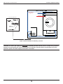
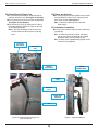
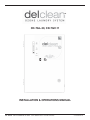
TM CD-7GL-30, CD-7GV-11 INSTALLATION & OPERATIONS MANUAL DEL OZONE · SAN LUIS OBISPO, CA 93401 · USA · 800-676-1335 · Fax: 805-541-8459 4-1513-01 Rev. C TABLE OF CONTENTS SECTION 1 SECTION 4 General Information Replacement Parts & Order Info 1A. Description ...........................................................1 1B. Specifications .......................................................1 4A. Ordering Information ............................................4 4B. Standard Replacement Parts List ........................4 SECTION 2 Warranty ..................................................................5 Operation Appendix 2A. Initial System Start-Up .........................................1 2B. Normal Operation.................................................1 2C. System Shut-Down ..............................................1 Appendix A: Venturi Installation Instructions ...............6 Appendix B: Pressure Installation Instructions ...........9 Appendix C: Safety .....................................................14 SECTION 3 Maintenance & Service 3A. System Electromechanical Overview ...................2 3B. PM Schedule ........................................................2 3C. Troubleshooting ....................................................3 3D. Contact Information ..............................................4 ALL Genesis CD Ozone Generators are NSF Listed. IMPORTANT SAFETY INSTRUCTIONS READ AND FOLLOW ALL INSTRUCTIONS. · Read this manual completely before attempting installation. · Install at least five (5) feet from tub water using nonmetallic plumbing. Install ozone generator no less than one (1) foot above the maximum water level to prevent water from contacting electrical equipment. Install in accordance with the installation instructions. · Connect to a grounded, grounding type receptacle only. · Do not bury cord. · Warning - To reduce the risk of electrical shock, replace damaged cord immediately. · Follow all applicable electrical codes. · Electric shock hazard. Be sure to turn power OFF and disconnect from power source before any service work is performed. Failure to do so could result in serious injury or death. · Warning - Short term inhalation of high concentrations of ozone and long term inhalation of low concentrations of ozone can cause serious harmful physiological effects. DO NOT inhale ozone gas produced by this device. · For your safety, do not store or use gasoline, chemicals or other flammable liquids or vapors near this or any other appliance. · A spontaneous and violent ignition may occur if oil, grease or greasy substances come in contact with oxygen under pressure. These substances must be kept away from oxygen regulators, cylinder valves tubing and connections, and all other oxygen equipment. SAVE THESE INSTRUCTIONS! DEL Clean Ozone Laundry Systems Installation & Operations Manual SECTION 1 SECTION 2 General Information Operation 1A. Description 2A. Initial System Start-Up The DEL Clean™ Ozone Laundry System described in this manual is designed to provide the benefits of ozonated water in an environmentally safe and effective manner. DEL Clean™ generators are National Sanitation Foundation (NSF) listed. The high quality, specially engineered components ensure efficient ozone output and reliable performance. 1. 2. 3. 4. 5. The DEL Clean™ Ozone Laundry System is safe and harmless to your equipment if installed properly. 6. 7. 8. 1B. Specifications Ozone output (+10%) Flow rate (max): % weight O3: 0-7 g/hr 7 scfh 3% Power Requirements: Domestic: 120VAC, 60 Hz, 1Ø, 6.0 Amp Upon completing all of the generator system connections as outlined in the appendix, you are ready to begin start up procedures. Check plumbing fittings. Check for proper voltage. Start Wash Cycle. Check for leaks. (CD-7GL-30 only) With the ozone isolation valve closed, adjust injector bypass valve to flow water through the injector. Open ozone isolation valve. Plug Ozone Generator into electrical outlet. (CD-7G-11 only) Verify that the “Ozone” light is on by the time the washer gets to the “Low Fill” level. Note: (CD-7GL-30 only) Your Injector Assembly is equipped with a bypass valve, close the valve by turning the handle clockwise until the proper suction is indicated as described in Section 2B. 2B. Normal Operation Once the Ozone Generator is plugged in and proper suction is applied, the cooling fan, air compressor, and oxygen concentrator will begin operating. Shipping Weight: Approx. 61 pounds / 27.5 kg Location Requirements: Mounting: Wall mount in a clean, protected area. Floor mounting kit optional. Ambient Temp: 40°F - 100°F (5°C - 40°C) Ventilation: Room should provide 6 air changes per hour minimum. Clearance: Provide a minimum of 4" clearance around unit. During the cold water fill the green 'Power' indicator and green 'Ozone' indicator will be illuminated. When the cold water fill cycle is completed, the red 'Vacuum' indicator will illuminate and the 'Ozone' indicator will turn off. Upon loss of suction the ozone will immediately shut off and the generator will go into a timed shut down mode. If proper suction is not reestablished within the pre-set time (normally 10 minutes) the generator will go into stand-by mode. In stand-by mode, the power and vacuum lights will be illuminated. Protection from weather elements must be provided for outdoor installations. Operating outside of the recommended temperature ranges may result in damage not covered under the manufacturer’s warranty. If the indicator lights are OK and the flowmeter is reading the proper flow (6-7 scfh)*, then the ozone generator is producing ozone. *Note: The CD-7G-11 will flow 10-20% less Note: Do not exceed the max flow rate specification as indicated in the specification sticker. If you experience complications see TROUBLESHOOTING section 3D or contact DEL technical support (See Section 3E). 1 DEL Clean Ozone Laundry Systems Installation & Operations Manual 7. Ventilation Fan: Provides fresh air and removes heat from the internal components. 8. Intake Screens: Easily removable screens keep debris from entering the enclosure. See figure 3. 9. Time Delay Relay: Provides delayed signal to shut down the Compressor/Oxygen system after extended loss of vacuum. The potentiometer on the relay adjusts delay from 1/2 minute to 10 minutes. 10. Dual Pole 25A Relay: Closes the circuit to the Ozone system and/or triggers the Time Delay Relay based on signal from the Vacuum switch. 11. Single Pole 30A Relay: Closes the circuit to Compressor/Oxygen system based on a signal from Time Delay Relay. 2C. System Shut-Down The following sequence of steps must be followed for servicing or for storage. 1. Close the ozone isolation valve on the ozone supply line. 2. Unplug the ozone generator. SECTION 3 Maintenance and Troubleshooting 3A. System Electromechanical Overview Refer to Figure 4 for component locations. 3A-1. Indicator Lights 1. Power: Green light indicates that power is being supplied to the ozone generator (Cabinet door must be closed). Generator will not start until proper vacuum is established (CD-7GL-30 only) or enough water is in the washer (CD-7G11 only). 2. Ozone: Green light indicates that power is being supplied to the high voltage Corona Discharge, ozone producing circuits. 3. Vacuum (CD-7GL-30 only): Red light indicates that vacuum is not being applied to the ozone generator. When sufficient suction is being supplied from the venturi injector during cold water fill, the red light will turn off. Note: The red light will be illuminated during normal operation when cold water is not filling the washer. 3A-2. Internal Components 1. Corona Discharge (CD) Module: The Generator module consists of a High Voltage electrode wrapped around a Teflon core inserted in a ceramic insulating tube. The assembly is encased in a thermally protected aluminum heat sink. 2. Power Supply: The fuse protected, selfregulated, High Voltage High Frequency Power Supply provides the ideal electrical signal for efficient ozone production. 3. Air Compressor: Produces and supplies compressed air to oxygen concentrator. 4. Oxygen Concentrator: Supplies concentrated, dry, oxygen feed gas to the ozone generator. 5. Lo Limit Vacuum Switch (CD-7GL-30 only): If the vacuum in the ozone output supply line falls below 2 in. Hg the switch will open causing the system to shut down. 6. High Sensitivity Pressure Switch (CD-7G-11 only): If the pressure in the actuating line goes above 4 inches of water, the switch will close, turning on the system. Figure 3: Intake Screen Replacement 3B. Preventive Maintenance Schedule The DEL Clean™ Ozone Laundry System requires very little maintenance beyond general housekeeping practices. DAILY: 1. Check ozone generator for proper operation. 2. Make sure green ozone light is illuminated during cold water fill cycles. 3. Make sure flow meter is indicating proper air flow. (~7 scfh). MONTHLY (or as buildup occurs): 1. Clean intake screens. 2. Perform general cleaning of cabinet interior. 3. Visually inspect compressor filter element. Replace as required. 4. Visual inspection of all plumbing, mechanical, and wiring in system. ANNUALLY: 1. Rebuild/replace ozone supply line check valve. 2. Replace oxygen supply line check valve. 3. Replace vacuum switch. 4. Verify oxygen output. Every 8750 hours of operation: 1. Rebuild air compressor. 2 DEL Clean Ozone Laundry Systems Installation & Operations Manual 15.6 DOOR SWITCH INDICATOR LIGHTS OXYGEN CHECK VALVE ( FLOW) FAN FLOWMETER AUXILLARY FUSE (CD-7GV ONLY) OXYGEN CONCENTRATOR PRESSURE SWITCH VACUUM SWITCH (CD-7GL-30) OR HIGH SENSITIVITY PRESSURE SWITCH (CD-7GV-11) DOOR LATCH HV POWER SUPPLY OZONE CELL ASSEMBLY AIR FILTER OZONE ACTUATION PORT 27.5 PRESSURE RELIEF VALVE (BACK SIDE OF COMPRESSOR) OZONE OUT DOOR LATCH COMPRESSOR MAIN FUSE/FUSEHOLDER OZONE CHECK VALVE SINGLE POLE 30 AMP RELAY DUAL POLE 25 AMP RELAY TIME DELAY RELAY Figure 4: Component Locations cold water fill. b. Check injector bypass valve and adjust if necessary to reestablish suction. Symptom: CD Module is not operating. Ozone output has dropped. 1. No power to the generator module from the power supply: a. Check fuse. b. Check H.V. cables for breaks or loose connections, replace if necessary. c. Check for power at input terminals of the H.V. transformers.* *CAUTION: HIGH VOLTAGE. Symptom: No air flow through the generator. The air flow meter indicates 0 scfh flow. 1. Injector not set properly (CD-7GL-30 only). a. Adjust injector bypass valve until proper air flow is indicated (~7 scfh). 2. Air compressor is not operating properly. a. Listen for air compressor operation. b. Check all tubing connections from the air compressor through the system for leaks. 3. Ozone supply tubing damaged. a. Check tubing for blockage or kinks. b. Check for loose or damaged fittings. 3C. Troubleshooting Knowledge of electrical applications is required for troubleshooting. Contact a certified electrician if you are unsure of your ability to service the equipment. Improper servicing will void generator warranty. If any condition persists, Contact DEL technical support for assistance. (See section 3E.) Symptom: “Power” light out when system is on. 1. No power to the generator module from the power source: a. Check circuit breaker at the power distribution box. b. Check for loose connections or wiring breaks from the power distribution box to the generator. 2. G.F.C.I. has tripped.* a. Check power cord and reset G.F.C.I. *If G.F.C.I. or breaker continues to trip after reset, call for technical assistance. Symptom: “Ozone” indicator light out. 1. Ozone power fuse is bad. a. Check fuse and replace if necessary. 2. Loss of Vacuum (CD-7GL-30 only). a. Check red vacuum indicator light. If light is on refer to corresponding symptom and corrective action below. Symptom: “Vacuum” indicator light is on indicating out of range vacuum being supplied (CD-7GL-30 only). 1. Injector not supplying adequate suction. a. Ensure water is flowing through injector during 3 DEL Clean Ozone Laundry Systems Installation & Operations Manual 3D. Contact Information: For Technical assistance: Call: (800) 676-1335 x213 E-mail: [email protected] Or visit or web site: www.delozonelaundry.com SECTION 4 Replacement Parts and Order Information 4A. Ordering information: For replacement parts call DEL at 1-800-676-1335 x213 Be prepared with the following information: -Customer Name -Customer Address -DEL Model # -DEL Serial Number -Date Purchased -Proof of Purchase 4B. Standard replacement parts list: 1. 2. 3. 4. 5. 6. 7. 8. 9. 10. 11. 12. Compressor Air Filter Element Compressor rebuild kit Check valve (external, on ozone supply line) Check valve (internal, on oxygen supply line) CD Ozone Cell (one required) O-rings for Ozone Cell Vacuum Switch Air intake screen Replacement door key Installation & Operations Manual Ozone tubing, 3/8" Teflon Ozone tubing, 1/4" Teflon 7-1120 2-0923-01 8-0330 7-1140-01 9-0927 7-0461 5-1748-01 8-0928-01 2-0015/KEY 4-1513-01 7-0126 7-0741 4 DEL Clean Ozone Laundry Systems Installation & Operations Manual DEL OZONE COMMERCIAL PRODUCT LIMITED TWO YEAR WARRANTY The limited warranty set forth below applies to products manufactured by DEL OZONE – 3580 Sueldo Street, San Luis Obispo, California 93401, and sold by DEL OZONE or its authorized dealers. This limited warranty is given only to the first retail purchaser of such products and is not transferable to any subsequent owners or purchasers of such products. Systems sized 65 grams or greater require factory commissioning and startup to maintain warranty as set forth below. DEL OZONE warrants that DEL or DEL authorized dealers will repair or replace, at DEL’s option, any part of such products proven to be defective in materials or workmanship within two (2) years of the date of receipt. Parts are covered under the two (2) year warranty when and only when the stated maintenance requirements are met. Contact tanks and degas valves have a ninety (90) day warranty. Compressor(s) must be maintained per operation and maintenance manual. Required maintenance includes a compressor rebuild after one (1) year or every 8,760 hours, which ever is reached first. Warranty does not include parts for compressor(s) rebuild kit(s), or other consumable items. See owner’s manual for complete maintenance details. This Warranty specifically excludes any components not manufactured by DEL OZONE that are external to the products covered, such as pumps, air compressors, monitors, tanks, or related components. DEL OZONE will assist with warranty claims for such components purchased through DEL OZONE; limited to the extent of the manufacturer’s standard warranty. ANY REPAIR OR REPLACEMENT WILL BE WARRANTED ONLY FOR THE BALANCE OF THE ORIGINAL TWO (2) YEAR WARRANTY PERIOD . NOTE: USE ONLY DEL AUTHORIZED DEL REPLACEMENT PARTS. USE OF ANY OTHER PART(S) WILL VOID THIS WARRANTY. Any replaced parts must be returned to DEL OZONE for warranty evaluation. THIS LIMITED WARRANTY DOES NOT INCLUDE ANY OF THE FOLLOWING: (a) (b) (c) (d) (e) (f) Any labor charges for troubleshooting, removal, or installation of such parts. Any repair or replacement of such parts necessitated by faulty installation, improper maintenance, improper operation, misuse, abuse, negligence, accident, fire, flood, repair materials, and/or unauthorized accessories. Any such products installed without regard to required local codes and accepted trade practices. Damage to unit caused by water backflow; Any implied warranty of merchantability or implied warranty of fitness for particular purpose, and such warranties are hereby disclaimed. DEL Ozone shall not be liable under any circumstances for loss of use of such product, loss of profits, direct damages, indirect damages, consequential damages, and / or incidental damages. This warranty gives you specific legal rights. You may have other rights which vary from state to state. Extended Warranties and Service Agreements are available. Contact DEL for additional details. TO OBTAIN WARRANTY SERVICE: DEL OZONE 3580 Sueldo, San Luis Obispo, CA 93401 Customer Service Number: (800) 676-1335 Fax Number: (805) 541-8459 E mail [email protected] PROVIDE: 1. Project, contact name, mailing address and telephone. 2. Installer/Mechanical Contractor. 3. Unit Part Number, Serial Number, and date of purchase. 4. The date of failure. 5. A description of the failure. After this information is provided, DEL Ozone may release a RETURN GOODS AUTHORIZATION (RGA) NUMBER. After receiving the RGA number the part in question must be returned to DEL Ozone, freight prepaid, with the RGA number clearly marked on the outside of the package. All preauthorized defective parts must be returned to DEL Ozone within thirty (30) days. Under no circumstances may any product be returned to DEL Ozone without prior authorization. Returns without the assigned RGA number on the outside of the package will be refused and shipped back to the sender at their expense. Upon receipt of preauthorized returned goods, DEL Ozone will repair or replace, at DEL Ozone’s option, the defective product(s) and return them (freight prepaid for products under warranty). Buyer’s acceptance of the product and use thereof constitutes acceptance of these terms. 4-1370-01_Rev.D 5 DEL Clean Ozone Laundry Systems Installation & Operations Manual APPENDIX “A” VENTURI INSTALLATION INSTRUCTIONS - CD-7GL-30 6 DEL Clean Ozone Laundry Systems Installation & Operations Manual A1.1.1.2. Refer to Figure 5. Mark the locations for the four mounting bolts and install anchors appropriate for the mounting surface. A1.1.1.3. Install the four mounting bolts through the Wall Mounting Brackets and into the anchors. A1.1.2. Floor Mounting (optional) The enclosure can be floor mounted to a solid, flat surface using the optional Floor Mounting Kit Part Number 9-5004. A1. Location The Ozone Generator is designed for wall mounting. See Figure 5. Mount generator in a clean, protected area, either indoors or outdoors. (See LOCATION REQUIREMENTS section 1B) It can also be mounted to the floor or deck with optional feet. (See REPLACEMENT PARTS section 5B) Locate generator out of reach of sprinklers or drainage spouts. Allow sufficient access for maintenance and all tubing and electrical wires. Ozone generator should be installed no less than one foot above the maximum water level. A1.2. Electrical A1.2.1. Main power circuit: The Ozone Generator is supplied with a standard power cord. Plug the cord into a standard 120V grounded, grounding type receptacle only. NOTE: The circuit must be protected by a ground-fault circuit interrupter (GFCI) installed in accordance with electrical codes. (A transformer is required for export power requirements). A1.1. Mounting A1.1.1. Wall Mount A1.1.1.1. Attach the Wall Mounting Brackets to the base and top of the enclosure using the four 1/4" x 1" long bolts and washers provided. 12.63 26.50 12.63 Figure 5: Wall Mount 7 DEL Clean Ozone Laundry Systems Installation & Operations Manual A2. Plumbing MPT-to-compression fitting (contained in parts bag) onto check valve. Insert one end of ozone tubing into the fitting, hold the tubing in place and tighten the fitting. Note: use a back-up wrench when tightening all fittings. A2.2.2. The injector assembly is also equipped with a Compression fitting. Connect the other end of ozone tubing to the injector suction port as described in step 1. See Figure 6. Ozone gas is introduced to the incoming cold water line using a venturi injector. Suction developed by the venturi allows the CD generator to operate safely under vacuum. A2.1. Injector Assembly: Plumb the Injector and/ or Degas Assembly into the water line according to the installation instructions for that assembly. A2.2. Ozone Gas Line A2.2.1. Install the ozone check valve (contained in parts bag) into the ozone output fitting on the generator. Apply Teflon tape, Mil T-27730A or equivalent, to threads. Flow direction is away from the generator. Install elbow or straight WARNING: The ozone gas supply line must have a back flow prevention device (such as a check valve) installed between the ozone generator cabinet and the point of injection to prevent water from backing up into the generator system. An ozone supply check valve is included. CHECK VALVE INSTALLATION Figure 6: Ozone Installation Line Drawing - Venturi 8 DEL Clean Ozone Laundry Systems Installation & Operations Manual APPENDIX “B” PRESSURE INSTALLATION INSTRUCTIONS - CD-7G-11 9 DEL Clean Ozone Laundry Systems Installation & Operations Manual B1. Location B2.2. Floor Mounting (optional) B2.2.1. The enclosure can be floor mounted to a solid, flat surface using the optional Floor Mounting Kit Part Number 9-5004. The Ozone Generator is designed for wall mounting. See figure 7. Mount generator in a clean, protected area, either indoors or outdoors. It can also be mounted to the floor or deck with optional feet. Locate generator out of reach of sprinklers or drainage spouts. Allow sufficient access for maintenance and all tubing and electrical wires. Ozone generator should be installed no less than one foot above the maximum water level. B3. Electrical B3.1. Main power circuit: The Ozone Generator is supplied with a standard power cord. Plug the cord into a standard 120V grounded, grounding type receptacle only. NOTE: The circuit must be protected by a ground-fault circuit interrupter (GFCI) installed in accordance with electrical codes. (A transformer is required for export power requirements). B2. Mounting B2.1. Wall Mount B2.1.1. Attach the Wall Mounting Brackets to the base and top of the enclosure using the four 1/4" x 1" long bolts and washers provided. B2.1.2. Refer to Figure 7. Mark the locations for the four mounting bolts and install anchors (not included) appropriate for the mounting surface. B2.1.3. Install the four mounting bolts through the Wall Mounting Brackets and into the anchors. 12.63 26.50 12.63 Figure 7: Wall Mount 10 DEL Clean Ozone Laundry Systems Installation & Operations Manual B4. Plumbing B4.2.4. Wrap Teflon tape around the male threads of the compression fitting. Then, screw the compression fitting into the stainless steel adapter. Note: Use a backup wrench when tightening fitting. B4.3. Ozone Gas Line B4.3.1. Install the ozone check valve (contained in parts bag) into the ozone output fitting on the generator. Apply Teflon tape, Mil T-27730A or equivalent, to threads. Flow direction is away from the generator. Install elbow or straight MPT-to-compression fitting (contained in parts bag) onto check valve. Insert one end of ozone tubing into the fitting, hold the tubing in place and tighten the fitting. Note: use a back-up wrench when tightening all fittings. B4.3.2. Connect the other end of the ozone tubing to the compression fitting of the thruwall ozone fitting installed in the sump. See Figure 8. Ozone gas is bubbled into the sump of the washer through the ozone supply line. B4.1. Ozone External Trigger Line: Tee into the washer pressure line using the supplied plastic B4.2. Through-wall Ozone Fitting: Well Nut Washer Stainless Steel Adapter Compression Fitting B4.1.1. Drill a 0.75” Dia. hole in the wall of the sump. See Figure 8 for reference location B4.2.2. Insert the well nut through the 0.75”Ø hole. B4.2.3. Insert the washer onto the stainless steel adapter then screw the stainless steel adapter into the well nut. Tighten down. 0.75" Ø Hole Figure 8: Through-wall Fitting Hole example 11 DEL Clean Ozone Laundry Systems Installation & Operations Manual Ozone External Trigger Line Cold Water In Pressure switch Cold Fill Valve Hot Water In Hot Fill Valve CHECK VALVE INSTALLATION Ozone Supply Line Figure 9: Ozone Installation Line Drawing - Pressure WARNING: The ozone gas supply line must have a back flow prevention device (such as a check valve) installed between the ozone generator cabinet and the point of injection to prevent water from backing up into the generator system. An ozone supply check valve is included. 12 DEL Clean Ozone Laundry Systems Installation & Operations Manual B5. Ozone External Trigger Line B6. Ozone gas destruct B5.1. Locate the pressure line inside the washer/ extractor electrical area. See Figure 10 (left top) B5.2. Cut pressure line and install the tee provided. See Figure 10 (left bottom) B5.3. Connect the 3/16”I.D. tubing from the tee to the Ozone External Trigger Line port on the side of the ozone generator. B5.3.1. Be sure the tubing is free of kinks and will not come into contact with any moving parts. Pressure Transducer B6.1. Using a length of EPDM rubber hose, connect the vent destruct to the 3” PVC vent port on the back of the washer. See Figure 11. B6.1.1. Secure the destruct to the vent with hose clamps. B7. Installation Completion B7.1. Run a test cycle to check for leaks and ozone functionality. B7.1.1. When the washer has filled, the ozone light on the front of the ozonator unit should illuminate green until the washer drains. B7.1.2. Refer to the troubleshooting section of the manual for any problems. Pressure Line Washer Front Panel EPDM Rubber Hose 3" PVC Vent Pressure Line Ozone Vent Destruct Tee Figure 10: Installing the Ozone Trigger Line in the Pressure Line Figure 11: Carbon Vent Destruct 13 DEL Clean Ozone Laundry Systems Installation & Operations Manual APPENDIX “C” SAFETY 14 DEL Clean Ozone Laundry Systems Installation & Operations Manual HEALTH HAZARDS OF OZONE FIRST AID Detection Levels General Ozone can be detected in air by its distinctive odor at concentrations of about 0.02 ppm. Although each nose varies, olfactory fatigue occurs quickly. As a result, DO NOT RELY ON ODOR AS A WARNING OF HIGH OZONE CONCENTRATIONS. First Action 1. If exposure to ozone causes headache or shortness of breath, immediately remove the patient to a fresh air environment. Second Action 1. Workers who have been exposed to low concentrations of ozone should be given oxygen to breathe while under the observation of trained personnel. 2. If exposure is sever, send for medical assistance immediately. The permissible exposure level (PEL) or time weighted concentration for ozone to which workers may be exposed os 0.1 ppm averaged over 8 hours, 5 days a week (OSHA). The short term exposure limit is 0.3 ppm average over 15 minutes. The concentration of 10 ppm ozone in air is generally accepted as immediately Dangerous to Life or Health (DLH). Inhalation First Action 1. Assess patient's breathing. 2. All unconscious patients must be placed in the drainage position (on their sides), so that fluids can drain from the airways once breathing has been restored. 3. Check pulse. Second Action 1. If breathing has ceased, start artificial respiration (rescue breathing is the most effective) method until breathing has been restored. 2. Send for medical assistance immediately. 3. If absent, begin cardiopulmonary resuscitation (CPR). Effects on Humans Ozone acts as a primary irritant, affecting mainly the eyes, upper respiratory tract and the lungs. Onset of pulmonary edema (fluid buildup in the lungs) may be delayed for a few hours after exposure. Inhaling ozone at concentrations of 50 ppm for 30 minutes can be fatal. Many people exposed to airborne ozone rapidly develop a headache, which often disappears after a few minutes in fresh air. Reduction in lung function due to scar tissue forming in the lung may occur due to long-term exposure to ozone at concentrations above 0.2 ppm, or a single high exposure. Although medical studies show no evidence of ozone causing cancer or lung allergies or harming the unborn, there is some evidence that the oxidizing power of ozone could lead to premature aging of the body as a whole. Eye Contact First Action 1. Effective irrigation should start immediately. Eyes should be irrigated for 30 minutes by the clock with running tap water or preferably normal saline. Second Action 1. Effective irrigation must be continued while en route to hospital. The owner of any ozone installation should advise any person who may be exposed to ozone that those with a history of heart or respiratory disease should take every precaution to avoid exposure to ozone. Precautions Workers with a previous cardiopulmonary (heart and lung) condition must consult their physician prior to working in an area in which they may be exposed to ozone. Significant alterations in cardiopulmonary functions have been documented when such workers have been exposed to low concentration of ozone. END OF DOCUMENT. 15 DEL Clean Ozone Laundry Systems Installation & Operations Manual OZONE Material Safety Data Sheet SECTION I: MATERIAL IDENTIFICATION IDENTITY: OZONE (Gaseous) FORMULA: O3 ISSUED: February, 1992 REVISED: March, 2009 Description (origin/uses): Occurs in atmosphere from UV light action on oxygen at high altitude. Commercially obtained by passing air between electrodes carrying a high voltage alternating current. Also found as a by-product in welding areas, high voltage equipment, or UV radiation. Ozone is used as an oxidizing agent in air and water disinfection: for bleaching textiles, oils, and waxes; organic synthesis as in processing certain perfumes, vanillin, camphor; for mold and bacteria control in cold storage. Cautions: A powerful oxidizing agent, ozone generally exists as a gas and is highly chemically reactive. Inhalation produces various degrees of respiratory effects from irritation to pulmonary edema (fluid in lungs) as well as affecting the eyes, blood, and central nervous system. Manufacturer/Supplier: On-site generation, equipment available from various suppliers, including: DEL Ozone Phone: (805) 541-1601 3580 Sueldo Street FAX: (805) 541-8459 San Luis Obispo, CA 93401 SECTION II: INGREDIENTS AND HAZARDS Ozone, CAS No. 10028-15-6: NIOSH RTECS No. RS8225000 1991 OSHA PELs 8-hr TWA: 0.1 ppm vol. (0.2 mg/m3) 15-min STEL: 0.3 ppm vol (0.6 mg/m3) 1991-1992 ACGIH TLV Ceiling: 0.1 ppm (0.2 mg/m3) 1990 IDLH 10 ppm 1990 DFG (Germany) MAK TWA: 0.1 ppm (0.2 mg/m3) Category 1: Local Irritant Peak Exposure Limit: 0.2 ppm 5 min momentary value, 8 per shift 1990 NIOSH REL Ceiling: 0.1 ppm vol. (0.2 mg/m3) Other Designations: Triatomic oxygen: CAS No. 10028-15-6, NIOSH RTECS No. RS8225000 SECTION III: PHYSICAL DATA Boiling Point: . . . . . . . Vapor Pressure: . . . . . Vapor Density (AIR = 1): Solubility in Water: . . . -169q F Melting Point: . . . . . . . . % Volatile by Volume: . . Molecular Weight: . . . . . pH: . . . . . . . . . . . . . . . . Critical Temperature: . . >1 ATM 1.6 0.49 ml @ 32q F (0q C), 3 ppm @ 20 q C -315.4q F (-193q C) 100% 48 Grams/Mole Not Listed 10.22q F (-12.1q C) Appearance and Odor: Colorless to blue gas (greater than -169q F): characteristic odor often associated with electrical sparks or lightning in concentrations of less than 2 ppm and becomes disagreeable above 1-2 ppm. CAUTION: Olfactory fatigue develops rapidly, so do not use odor as a preventative warning device. SECTION IV: FIRE AND EXPLOSION HAZARD DATA Flash Point: . . . . . . . . Extinguishing Media: . Nonflammable Use large amounts of water spray or fog to put out fires involving ozone. Use appropriate fire-fighting techniques to deal with surrounding material. Special Fire Fighting Procedures: Wear a self contained breathing apparatus with full face pieces operated in a pressuredemand or other positive-pressure mode. Unusual Fire/Explosion Hazards: Decomposition of ozone into oxygen gas, (O2), can increase strength of fire. SECTION V: REACTIVITY DATA Stability: Ozone is not stable. Hazardous polymerization cannot occur. Chemical Incompatibilities: Ozone is chemically incompatible with all oxidizable materials, both organic and inorganic. Conditions to Avoid: Ozone is unstable at room temperatures and spontaneously decomposes to oxygen gas. Avoid ignition sources such as heat, sparks, and open flame. Keep away from strong reducing agents and combustible materials such as grease, oils, and fats. Products of Hazardous Decomposition: Ozone spontaneously decomposes to oxygen gas, even at room temperatures. 4-0697_ Rev.B 16 DEL Clean Ozone Laundry Systems Installation & Operations Manual SECTION VI: HEALTH HAZARD DATA Carcinogenicity: Ozone is not listed as a carcinogen by the NTP, IARC, or OSHA. Primary Entry: Inhalation Target Organs: Respiratory system, eyes, blood. Summary of Risks: There is no true threshold limit and so no exposure (regardless of how small) is theoretically without effect from ozone’s strong oxidative ability. Ozone passes straight to the smallest bronchioles and alveoli and is not absorbed by mucous membranes along the way. Initial small exposure may reduce cell sensitivity and/or increase mucous thickness producing a resistance to low ozone levels. Short exposure to 1-2 ppm concentrations causes headache as well as irritation to the respiratory tract. but symptoms subside when exposure ends. High concentrations of ozone produce severe irritation of the eyes and respiratory tract. Exposure above the ACGIH/OSHA limits produce nausea, chest pain, coughing, fatigue, reduced visual acuity, and pulmonary edema. Symptoms of edema from excessive exposure can be delayed one or more hours. Inhalation of >20 ppm for an hour or more (>50 ppm for 1/2 hour) can be fatal. Acute Effects: Acute damage from ozone appears to be mainly from its oxidizing effect on contact with tissue. Chronic Effects: Respiratory disease. Deleterious effects on lungs and acceleration of tumors have been reported. Medical Conditions Generally Aggravated by Long-Term Exposure: History of respiratory or heart disorders. First Aid: Remove from ozone containing air, get prompt medical help*, administer oxygen if necessary. Eye Contact - Gently lift eyelids and flush eyes continuously with flooding amounts of water for 15 minutes or until transported to a medical facility*. Inhalation - Remove exposed person to fresh air, support breathing, administer humidified oxygen as needed, get medical help*. Ingestion - Highly unlikely since ozone is a gas until -169q F, * GET MEDICAL ASSISTANCE = APPROPRIATE IN-PLANT, PARAMEDIC, or COMMUNITY. Get prompt medical assistance for further treatment, observation, and support after first aid. SECTION VII: PRECAUTIONS FOR SAFE HANDLING AND USE Steps to be Taken in Case of Spill/Leak: 1. 2. 3. 4. Discontinue production Isolate and vent area Immediately notify personnel Deny entry 5. Follow applicable OSHA regulations Disposal: Provide ventilation to dilute and disperse small amounts of ozone (below OSHA PELs) to outside atmosphere. Follow federal, state, and local regulations. Handling/Storage Precautions: Ensure proper personnel training and establish emergency procedures. SECTION VIII: CONTROL MEASURES Respiratory Protection: High Level (>10 ppm) - Self Contained Breathing Apparatus: MISH/NIOSH approved. Low Level (0.3 - 10 ppm) - Canister Type (carbon) respirator may be used. Eye Protection: Wear chemical safety goggles if necessary to work in high ozone (>10 ppm). Skin Protection: Effects of ozone on skin are minimal to non-existent. Ventilation: Provide general and local exhaust ventilation to dilute & disperse small amounts of ozone into outside atmosphere. SECTION IX: SPECIAL PRECAUTIONS AND COMMENTS Storage Segregation: Prevent ozone from coming into direct physical contact with strong acids or bases or with strong oxidizing/reducing agents. Engineering Controls: Install ventilation systems capable of maintaining ozone to concentrations below the ACGIH/OSHA exposure limits (see sect. II). Install ambient ozone monitor(s) configured to shut down ozone equipment and turn high speed ventilation on. 4-0697_ Rev.B 17