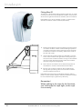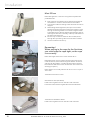
1
Windlass Systems Installation and user manual Rev3.2 is rd th a p bo ee n K lo ua an m ! SLEIPNER MOTOR AS P.O. Box 519 N-1612 Fredrikstad Norway Tel:+47 69 30 00 60 Fax:+47 69 30 00 70 www.side-power.com [email protected] Made in Norway EN Side-Power Engbo MAXI 31/32/33/34/40/43/44 © Sleipner Motor AS 2014 Content Introduction of MAXI- series...........................................................................................................................................................................3 User guide..........................................................................................................................................................................................................4 Before installation..............................................................................................................................................................................................6 Installation .........................................................................................................................................................................................................8 Fitting MAXI31.................................................................................................................................................................................................10 Fitting MAXI 32................................................................................................................................................................................................11 Fitting MAXI 33................................................................................................................................................................................................13 Fitting MAXI 34................................................................................................................................................................................................14 Fittting MAXI 40...............................................................................................................................................................................................17 Fitting MAXI 43/44..........................................................................................................................................................................................18 Fitting of auto stopp and fitting the stop indicator/brass wire..................................................................................................................19 Wiring diagram...............................................................................................................................................................................................21 Electrical installation.......................................................................................................................................................................................22 Electrical wiring...............................................................................................................................................................................................22 Fitting control box...........................................................................................................................................................................................23 Dimensions......................................................................................................................................................................................................25 Maintenance and service...............................................................................................................................................................................28 Technical data..................................................................................................................................................................................................31 Troubleshooting .............................................................................................................................................................................................32 Notes ...............................................................................................................................................................................................................33 2 SP ENGBO MAXI 31 32 33 34 40 43 44 Rev3.2July_2014 Introduction Congratulations on your new windlass and thank you for selecting a Side-Power Engbo windlass. We hope your windlass will meet your expectations. Please note that this requires that the windlass will be installed and used in accordance with this manual in an environment with the correct conditions for proper operations. This includes the necessary voltage capacity for the windlass motor as well as correct placement of the windlass, rope, anchor and anchor bracket. Introduction of MAXI 31, 32, 33, 34, 40, 43, 44 Side-Power Engbo MAXI windlasses are a generic term for Side-Power Engbo windlass with 1000 or 1500 W, 12 or 24V. Some of the models is suitable for mounting stern, some on the bow and some both stern and bow. Side-Power Engbo MAXI is intended for boats larger than approx. 25 feet. These windlasses, except MAXI 33, is an true freefall windlass, it means that the anchor falls out and down to the bottom immediately after the switch to “drop anchor” (down) has been pressed. It is the anchor’s weight on the outside of the anchor bracket that determines how quickly it falls out. It is therefore important to avoid unnecessary friction between the ropes and hull, rolls or rope guides. IMPORTANT! This manual contains information you need to know before installing the windlass. Therefore, please read it carefully. General procedure for use of Side-Power Engbo windlasses Read the operating manual carefully before installing and using the windlass. Please note that strong forces are involved, so please use the windlass carefully and make sure, for example, that: • • • • • • • • • • • • • You do not get your fingers caught up in the rope, chain, anchor, rollers or sheaves. The rope/chain is always under observation when the anchor is being raised. Everyone on board has been informed of how the windlass is working. You always operate the winch from a place that provides an unobstructed view of the anchor while it is being raised. This will help prevent “unpleasant surprises” that may damage the boat and persons. You muat release the switch for a little while if the windlass is straining to raise the anchor. When the boat has started moving backwards, you can start the windlass again. This will make it easier for the windlass to operate, and it will use less power. If the anchor is stuck on the seabed: Release some rope and tie it up to a cleat on the boat. Then use the boat engine to free the anchor. Once the anchor has been freed, use the windlass in the usual manner. The windlass can run for max. 3 minutes at normal load. The anchor must always be secured to the boat while the boat is travelling. Use the security line. Disconnect the power to the windlass once the boat is sailing. Children must not operate the windlass. The windlass is operated with care to avoid unnecessary damage/injury. The windlass features an mainswitch unit with an miniature circuit breaker that turns off when overloaded. If the windlass overloads rapidly, wait 5 minutes and try again. Sleipner Motor AS is not responsible for injury or damage as a result of the use of the windlass system. IMPORTANT! Always keep the boat’s motor running when operating the windlass. Always turn off the power to the windlass when it is not being operated. The anchor must always be secured to the boat while the boat is sailing. Use the security line. Always use original Side-Power Engbo anchor line. Always make sure the anchor has hit the sea bottom before pushing the “up” button. Windlass and accessories must be installed and used in a manner that will not result in damage or injury to human beings, boats or surroundings. • The installation must be done or controlled by people with expert knowledge of high current and low voltage. • Do not mount any windlass parts in areas where there may be flammable or explosive gases. • Electronic devices and cables must not be exposed to moisture • • • • • • SP ENGBO MAXI 31 32 33 34 40 43 44 Rev3.2July_2014 3 User guide Docking with remote control 1. 2. 3. 4. 5. Make sure the boat engine is running during anchoring. Decide where you want to drop anchor. Check that the safety line on the anchor has been loosened. Turn ON the main switch of the windlass. When the main switch for the windlass has been switched off, you must press down both ON buttons on the remote, before pressing DOWN button to release the anchor. Docking with fixed switch panel 1. 2. 3. 4. Press the down button for at least 1 sec. The anchor will drop. The windlass is now released and the rope will run out in step with the progress of the boat towards land. Tie up the boat Note! If you are using a free-fall chain windlass, the high weight of the chain may result in the full length of the chain being pulled out. If so, make sure to take up the slack once you have tied up the boat. Note!The windlass will always wind in slowly before it switches to full speed. Departing 1. 2. 3. 4. 5. Start the boat engine to charge the battery. Turn on the main switch of the windlass. Release the mooring from land. Activate the windlass. Keep the up button depressed, and the windlass will pull the boat away from land. The windlass will pull the anchor up at full speed until the first auto stop is activated. After the first auto stop: 1. 2. 3. 4. 5. 6. Release the up button, press again and keep depressed. The windlass will continue to raise the anchor slowly until the second auto stop is activated, stopping the windlass completely. The anchor will then be correctly seated in the anchor bracket. Attach the safety line to the anchor. Turn off the main switch of the windlass. Have a pleasant sailing! Note! This ONLY applies for rope windlasses and requires the anchor rope to be correctly fitted with brass wire markers. Important! Keep an eye on the anchor when it leaves the water and seats in the anchor bracket. This will allow you to stop the windlass and prevent damage if the anchor pulls up foreign objects from the seabed. Note! If the windlass is straining while raising the anchor, it would be a good idea (and save power) to run the windlass in periods. Once the boat has begun to move backwards, you can release the up button and then run the windlass in periods. 4 SP ENGBO MAXI 31 32 33 34 40 43 44 Rev3.2July_2014 User guide Wireless remote control RC-11E The remote is waterproof and floats if dropped into the water. It has under normal conditions an radio range of 15m. See own manual for more information. Note! Remote and receiver is normally connected and ready to use. • • Remote control is turned ON by pressing both ON buttons.F To ensure a long lifetime, the remote control switches off automatically 4 min. after the last button was pressed. Anchor DOWN • • When the remote control is switched on, you can drop the anchor by pressing the “down” button. Keep this button depressed for at least 1 second to drop the anchor. The windlass will then run out slowly in the beginning to ensure the correct release function. Down Anchor UP • Up IMPORTANT! • • When the anchor has dropped to the seabed, press the “up” button to tighten the slack. The windlass will continue to winch in as long as you keep the “up” button depressed. If the remote control has switched off automatically (i.e. if you have not pressed a button for more than 4 min) you must first switch ON, and then immediately press UP start to wind in the anchor rope/chain. The windlass always starts to operate at reduced speed before increasing to full speed. Always turn off the power to the windlass when it is not being operated. The anchor must always be secured to the boat while the boat is sailing. Use the safety line supplied. SP ENGBO MAXI 31 32 33 34 40 43 44 Rev3.2July_2014 5 Before installation • • • • • Remember! Make sure to have all necessary tools ready Unpack and organize all components Prepare and control the areas where the different parts can be mounted. Follow the mounting instructions When winching the rope for the first time after mounting, make sure the rope is tight, so the rope is pulled inn correctly. Placing the parts You must plan the placement of the following parts: • Winch/motor • Brackets for anchor and windlass • Cables • Switch panel • Controlbox • Line guide • Main switch/ miniature circuit breaker General The windlass should be positioned as high as possible to allow maximum space for the rope that will be stored below the windlass. The height from the bottom of the wall where the rope is stored to the bottom edge of the line wheel should be at least 50 cm, and the area should be at least 40 x 40 cm to allow room for 50 m x 16 mm anchor rope. This will prevent the rope from bunching under the windlass and assure sufficient friction between the line wheel and the rope. See the specific descriptions for the separate windlass models. Note! Remember to attach the end of the rope somewhere inside the boat. 6 SP ENGBO MAXI 31 32 33 34 40 43 44 Rev3.2July_2014 Before installation Anchor bracket Fit the windlass so that the rope is wound up in line with the anchor bracket (see pictures 1 and 2) – a numerous different models are available. The anchor bracket is working as a guide for the rope when the anchor is on the seabed and as a “seating point” for the anchor once it has been raised. Use of anchor bracket The bracket for the rope must be installed with the rollers outside the platform to ensure the anchor/rope run untouched of the platform. Standard platform roller or hinged platform roller 1 2 If the windlass is fitted low in relation to the bathing platform, so the angle between the bathing platform and the rope is too small ,and if you are using a Bruce anchor, you should use an Side-Power Engbo hinged platform roller. Hull conduit / Line guide It will often be necessary to install a hull implementation with a roller that guides the rope with low friction through the hull. Rope Side-Power Engbo supplies original woven anchor rope with a lead core in the whole length of the rope along with a fine special thimble that will not snag on the pulley or bracket when the anchor is dropped. This rope has been specially designed for Side-Power Engbo anchor windlasses and is a precondition for problem-free operation of the system. Supplied in various lengths and dimensions. The SP Engbo Maxi range generally uses 16 mm line. If the available space for storing the line is limited, 14mm line could be an alternative. Safety line Once the anchor is seated in the anchor bracket, it must be secured with the safety line supplied. This prevents the anchor from dropping unintentionally. Auto stop Side-Power Engbo MAXI winches for anchor lines feature an advanced electronic auto stop switch that stops the windlass automatically, twice. The first stop comes just before the anchor reaches the anchor bracket. The windlass can then only be operated at low speed until it stops for the second time once the anchor is seated correctly in its bracket – ready to be dropped next time. SP ENGBO MAXI 31 32 33 34 40 43 44 Rev3.2July_2014 7 Installation General Position the windlass as high as possible so that there is plenty of space for the rope under it. The bottom edge of the line wheel should be at least 50 cm above the surface on which the rope (or chain) is to lie. This will leave room for 50 m of 16 mm woven Robline anchor rope or approx. 30 m of chain. If the height is less than 50 cm, check that the rope (or chain) does not bunch up against the underside of the windlass. If this is the case, use a shorter rope (or chain). We recommend side position of the windlass. Avoid any conflict between the anchor and the side wave that turns in directly behind the boat. Note! Remember to attach the end of the rope somewhere inside the boat. Placing the platform roller Fit the anchor bracket with the rollers beyond the edge of the platform so that the anchor/rope clears the platform when the anchor is raised. Line guide in the stern Check that the opening in the hull for the rope is correct in relation to the direction of the rope. To prevent unnecessary wear, the rope should not touch the edge of the opening either vertically or horizontally. The opening must be oval (from top to bottom) to accommodate the friction in the rope roller when the windlass is used. Line guide If it is difficult to lead the rope directly from the line wheel to the anchor roller, it is a good idea to use a hull conduit/line guide with rollers, for instance 39-76000 or the simple 39-79000 to lead the rope through the hull. The line guide may be installed with studs as shown in picture. 8 SP ENGBO MAXI 31 32 33 34 40 43 44 Rev3.2July_2014 Installation Anchor brackets Standard platform roller, long Hinged platform roller Tilt bracket Anchor davit SP ENGBO MAXI 31 32 33 34 40 43 44 Rev3.2July_2014 9 Installasjon Fitting Maxi 31 The Maxi 31 is designed for fitting outside on the stern or inside on the stern side of a vertical bulkhead. The Maxi 31 has the line wheel on the right-hand side of the windlass, seen from behind. Note! Make sure to fit the windlass correctly in relation to the direction of rotation of the line wheel. (See sketch) 1. Position the windlass as high as possible on the stern. Draw around the windlass. Use the enclosed drilling template to mark the screw holes on the supporting surface. Use bolts to attach the windlass. If necessary, reinforce the inside of the hull with a plate. 2. If the surface where the windlass is to be fitted is not even so the entire windlass rests against the hull/supporting surface, the surface must be evened out using an intermediate layer to prevent damage to the hull and/or the windlass when the fixing bolts are tightened. 3. Drill a hole for the cables and run these through the hull. Use Sikaflex or similar to seal the hole for the cables. 4. Run the rope via the line wheel on the windlass, down through the rope/chain guide and under the line wheel. Use the windlass to wind it up. Note! We recommend using an adapted container made of plastic or other weather-resistant material beneath the windlass to ensure that the rope is gathered up efficiently. Remember! When pulling in the rope for the first time, you must keep the rope tight, so the rope run correctly. 10 SP ENGBO MAXI 31 32 33 34 40 43 44 Rev3.2July_2014 Installasjon Fitting Maxi 32 The Maxi 32 is designed for fitting outside on a rope box or outside/inside on a horizontal surface. The Maxi 32 has the line wheel on the right-hand side of the windlass, seen from behind. Note! Make sure to fit the windlass correctly in relation to the direction of rotation of the line wheel. (See sketch) 1. 2. 3. 4. 5. Remove the four 8 mm fixing bolts from the bottom of the windlass. Position the enclosed template correctly, so that the line wheel is on the correct side. Mark the position of the holes for the fixing bolts, the hole for the part of the winch that is to pass through the deck, and the opening for the rope. Align the winch and the roller to each other. Then use four of the enclosed bolts to secure the windlass firmly in position. Fit the windlass so that there is at least 50 cm of free height from the underside of the line wheel to the bottom of the well where the rope or chain is to lie. The area where the rope or chain is to be stored should measure at least 40 cm x 40 cm. Note! This space is normally sufficient for 50 m x 16 mm rope or 30 m chain. Remember! When pulling in the rope for the first time, you must keep the rope tight, so the rope run correctly. SP ENGBO MAXI 31 32 33 34 40 43 44 Rev3.2July_2014 11 Installation Maxi 32 box Note! SP Engbo line / chain box is supplied complete with predrilled holes. 1. 2. 3. 4. 5. Drill a hole for the cables and run these through the hull. Use Sikaflex or similar to seal the hole for the cables. Connect the cables according to the electrical connection diagram. When fitting the fibreglass box, the open end must be fitted to the shape of the stern and fixed in position using through-and-through bolts to connect the angle bracket supplied directly to the hull. Adjust the brackets to the correct angle and fix them internally, at the top and bottom of the side panel of the box. Run the rope via the line wheel on the windlass, down through the rope/chain guide and under the line wheel. Use the windlass to wind it up. Remember! When pulling in the rope for the first time, you must keep the rope tight, so the rope run correctly. Note! The length of the box must be at least 40 cm. Note! Remember to secure the end of the rope/chain to the inside of the box. (Drill a hole through the bottom of the box and through the platform, and then fit the bracket supplied. Remember to drill holes in each of the lower stern corners for drainage purposes.) Note! The box is normally sufficient for 50 m x 16 mm rope or 30 m chain. Tilt bracket mounted on a box. Standard box roller (65-00001) Fixed to the angled surface on the stern end of the box. Fit the box roller with the angled side of the bracket down. Tilt bracket 61-30006/61-30007 Fixed to the angled surface on the stern end of the box. 12 SP ENGBO MAXI 31 32 33 34 40 43 44 Rev3.2July_2014 Installation Fitting Maxi 33 The Maxi 33 is designed for horizontal installation on the fore or aft deck. Note! Make sure to fit the windlass correctly in relation to the direction of rotation of the line wheel. 1. 2. 3. 4. 5. Start by locating the correct position for the windlass, so that the direction of the chain is in line with the anchor bracket. Then mark the centre of the windlass. In most cases, it is simplest to use the windlass fixing plate as a template. Place the fixing plate on the boat and mark the screw holes, the centre hole for the gear, and the runthrough hole for the chain. Remember to round off the edge of the run-through hole for the chain so that the chain does not catch on sharp edges. To ensure the chain does not come into conflict with the motor on the inside, the gear should be mounted so that the motor points in a different direction than the runthrough hole. Then run the chain around the line wheel and down into the hole. Remember! When pulling in the rope for the first time, you must keep the rope tight, so the rope run correctly. SP ENGBO MAXI 31 32 33 34 40 43 44 Rev3.2July_2014 13 Installation Fitting Maxi 34G The Maxi 34-G is designed for fitting vertically on a longitudinal bulkhead with the line wheel outside and the windlass itself inside. The Maxi 34-G is available with the line wheel on the right or left-hand side of the windlass, as seen from the rear. Note! Make sure to fit the windlass correctly in relation to the direction of rotation of the line wheel. (See sketch) 1. Place the enclosed template on the surface where the winch is to be fitted – ideally as high as possible – and mark the drilling holes. 2. Alternatively, you can use the windlass fixing plate as a template. If you choose to do so, remove the white plastic cover and remove the line wheel and spring so that the fixing plate is free of fitted parts. Remove the six screws that hold the fixing plate to the gear. 3. Place the fixing plate on the surface where the windlass is to be fitted and mark the screw holes, the centre hole for the gear, the hole for the auto stop switch (on the lower stern side edge of the fixing plate), and the run-through hole for the rope. The simplest way to position the run-through hole for the rope is to drill the fitting holes for the fixing plate and then use a couple of screws to fasten this plate temporarily to the boat. Position the plastic cover, make sure that the cover overlaps the hole by approx. 5 mm at the bottom, and then mark the lower edge of the cover on the fitting surface. Then make the holes with an appropriate drill and hole-cutter. Remember to round off the outside upper edge and the inside lower fore edge of the run-through hole to prevent the rope from catching on sharp edges. 4. Then fasten the fixing plate to the boat. Remember to draw the auto stop switch from the lower stern side hole of the fixing plate before fitting the gear. To prevent the rope becoming entangled with the motor on the inside of the boat, fit the gear so that the motor is pointing directly forward, facing slightly up or slightly down. 5. Then fit the anchor bracket and check that the anchor fit correctly on the rollers. 6. Fit the sheaves and covers, the rope guard, the rope guide and the spring (pos 52, 54 and 58). Then fit the auto stop switch in the hole in the rope guard and adjust it so that the reciprocal part sticks approx. 1 mm out from the outside of the bracket, towards the rope. 7. Then pull the rope through the hole in the cover and run it between the line wheel and the rope guide. 8. Put the white plastic cover in position. Mark the run-through hole for the rope in the cover. Make an oval hole – approx. 40 mm vertical and 20 mm horizontal – in the cover. (for instance, cut 2 holes in towards each other with a 20 mm hole-cutter. Then remove the material between the holes.) Remember! When pulling in the rope for the first time, you must keep the rope tight, so the rope run correctly. 14 SP ENGBO MAXI 31 32 33 34 40 43 44 Rev3.2July_2014 Installation Drawing - Maxi 34-G – line wheel, rope guide, rope guard and fixing plate Note! The bolt (pos 17) that attaches the line wheel to the axle must be secured with contact adhesive (e.g. Locktite or similar). Recommened torque for bolts, 20Nm. SP ENGBO MAXI 31 32 33 34 40 43 44 Rev3.2July_2014 15 Installation Fitting Maxi 34-D The Maxi 34-D is designed for horizontal installation on the fore or aft deck. Note! Make sure to fit the windlass correctly in relation to the direction of rotation of the line wheel. (See sketch) 1. 2. 3. 4. 5. 6. 7. 8. 9. Start by locating the correct position for the windlass, so that the direction of the rope is in line with the anchor bracket. Then mark the centre of the windlass. In most cases, it is easy to use the windlass fixing plate as a template. Remove the white plastic cover and remove the line wheel, rope guides and spring so that the fixing plate is “clean”. Remove the six screws that hold the fixing plate to the gear. Place the fixing plate on the boat and mark the screw holes, the centre hole for the gear, the hole for the auto stop switch (on the front port side edge of the fixing plate), and the run-through hole for the rope. The easiest way to position the run-through hole for the rope is to drill the fitting holes for the fixing plate and then use a couple of screws to fasten this plate temporarily to the boat. Put the plastic cover on and mark the forward edge of the cover on the contact surface. Use an appropriate hole-cutter and make sure that the cover overlaps the outer edge of the hole by around 5 mm. Then make the holes with an appropriate drill and holecutter. Remember to sand the upper aft edge and the lower fore edge of the run-through hole for the rope, to prevent the rope from catching on sharp edges. Then screw the fixing plate firmly in place on the boat. Remember to draw the auto stop switch from the front port side hole of the fixing plate before screwing the gear firmly in place. To prevent the rope becoming entangled with the motor on the inside of the boat, fit the gear so that the motor is pointing directly forward, facing the port or starboard side. Then fit the anchor bracket and check that the anchor fit correctly on the rollers. Fit the sheaves and covers, the rope guard, the rope guide and the spring. Then fit the auto stop switch in the hole in the rope guard and adjust it so that the sensor face protrudes approx. 1 mm towards the rope. Then pull the rope through the hole in the cover, run it between the line wheel and the rope guide and down below the deck. Finally, fasten the cover in place. Remember! When pulling in the rope for the first time, you must keep the rope tight, so the rope run correctly. 16 SP ENGBO MAXI 31 32 33 34 40 43 44 Rev3.2July_2014 Installation Fitting Maxi 40 The Maxi 40 is designed for fitting inside on the stern or on the bow side of a vertical bulkhead. The Maxi 40 has the line wheel on the left-hand side of the windlass, seen from behind. Note! Make sure to fit the windlass correctly in relation to the direction of rotation of the line wheel. (See sketch) The drilling template (only applies to the Maxi 40) is designed to lie on the outside of the hull when you mark the holes. For marking inside, you must reverse the template so that the holes in the template match the windlass. 1. Make sure that the opening in the hull for the rope is positioned correctly in relation to the direction the rope takes out through the hull. To prevent unnecessary wear, the rope should not touch the edge of the opening either vertically or horizontally. The opening should be oval (top to bottom) to accommodate the vertical play in the rope when the windlass is used. 2. Position the template correctly, so that the line wheel is on the correct side. Mark the position of the opening for the rope and then drill the hole. Note! Make sure to position the windlass correctly in relation to the rope and anchor bracket so that the windlass line wheel and the roller are in line. 3. 4. 5. 6. 7. Once you have made the opening for the rope in the stern, you can install the windlass. Use a clamp or similar to fit the anchor bracket temporarily to the outside of the boat. Run the anchor rope tightly between the external anchor bracket and the track of the windlass line wheel. Hold the windlass in place inside the boat and adjust the position so that the rope is led correctly through the opening in the stern. Once you have found the correct position, mark around the windlass fixing plate before removing the windlass. Place the drilling template so that it matches the mark you drew on the stern, and mark the holes for the fixing bolts. Use a 9 mm bit to drill the holes, and then fit the windlass. Note! If you are to use a rope conduit/line guide with guide rollers (68-00008), you can use the internal frame of the conduit as the template for the opening. 8. 9. If necessary, use an intermediate panel between the windlass and the hull to adjust the windlass in relation to the direction of pull on the rope. After final adjustment of the windlass position, tighten the bolts. Run the rope via the line wheel on the windlass, down through the rope/chain guide and under the line wheel. Use the windlass to wind it up. Remember! When pulling in the rope for the first time, you must keep the rope tight, so the rope run correctly. SP ENGBO MAXI 31 32 33 34 40 43 44 Rev3.2July_2014 17 Installation Fitting Maxi 43/44 Maxi 43 is made to simplify the fitting process. The bracket can be turned 360 degrees. It ca be mounted hanging, standing or vertically at the bulkhead. The rope guide can be turned seperately to get maximum friction in the line wheel, and also get correct direction against the rope guide. If you want the line wheel on the left side seen from stern, it is a Maxi 44. Note! Make sure that the windlass is mounted in the correct direction regarding the direction of rotation of the line wheel. It is important that the hole pattern in the hull is correctly positioned relative to the direction of the rope through the hull. To avoid unnecessary wear and tear it should not touch the edges of the hole, either vertically or horizontally. Note! If the hull implementation with rollers is (39-76000) to be used, the bracket of the winch must be turned 180 degrees, use the hole template. When holes for pin bolts and the rope are made, the windlass is ready for mounting. If you use a rope guide without a roller (39-74000) or rope guide with one roller (39-75000), you must at first mount the rope guide, then the first half of the mounting bracket and fasten it to the rope guide. Lift/place now the windlass inside with the other half of the mounting bracket. Attach both parts with the included bolts, and just attach the bolts. The windlass is now in place and ready for adjustments. Adjust now the windlass to your wanted/correct angel and tighten the bolts to the mounting bracket. (20NM, 8mm Hex wrench). The windlass is now mounted. Make sure the direction of the windlass compared to the anchor bracket is correct. The line wheel and anchor roller must på aligned. When everything is aligned fasten the anchor bracket temporarily with a clamp or similar. Tighten the anchor rope between anchor bracket and in track of the line wheel of the winch. Then fasten the anchor bracket. Run the rope in place through hull implementation/rope guide, around the line wheel and through the line guide, adjust then the rope with a minimum of 90 degrees around the line wheel. Then tighten the line wheel (6 NM) with a hex wrench (6mm). Then run the rope into the winch. Remember! When pulling in the rope for the first time, you must keep the rope tight, so the rope run correctly. Standard box roller (65-00001) Fixed to the angled surface on the stern end of the box. Fit the box roller with the angled side of the bracket down. Tilt bracket 61-30006/61-30007 Fixed to the angled surface on the stern end of the box. 18 SP ENGBO MAXI 31 32 33 34 40 43 44 Rev3.2July_2014 Installation Autostopp All Side-Power Engbo Maxi windlasses feature an electronic auto stop function. An electronic auto stop switch is positioned below the windlass line wheel and registers the brass wire indicators attached to the rope. When the first brass wire indicator passes the sensor, the windlass will stop. If you release the button on the control panel or remote control and then press it again, the windlass will continue to reel in the anchor at low speed until the second brass wire indicator passes the sensor. The windlass will then stop again. Adjusting the auto stop switch • This feature is normally correctly adjusted on delivery. The flat end should usually protrude approx. 1 mm from the holder towards the rope. If you need to adjust it, loosen the bolt that holds the auto stop switch in place and adjust it to the required position. Then tighten the bolt again. Note! Make sure that the anchor line cannot snag on the inductive sensor. Auto stop – fitting the stop indicator/brass wire 1. 2. 3. 4. 5. 6. 7. 8. An electronic auto stop switch is positioned below the rope guard. This switch triggers the auto stop function when the anchor has been raised. To activate the switch, two brass wire indicators are fitted to the rope to determine when the windlass is to stop. (Cut the enclosed brass wire in two). To position the brass wire indicators in the correct places on the rope, raise the anchor until the thimble is approx. 30 cm below the anchor bracket (raise the anchor slowly during the last stretch) and mark the rope right next to the auto stop switch. Then carefully raise the anchor completely and fit it in the bracket. Make a new mark on the rope by the sensor. Position the wire indicators by the marks (Picture 1) Use an appropriate tool to pierce a hole through the rope (Picture 2). Push the brass wire through the rope and fold it lengthwise along the rope (Picture 3). Wind the free end of the brass wire five times around the rope and over the other end of the wire (Pictures 4–5). Wind the free ends together, cut the twist down to approx. 5 mm and bend it in under the wire wrap so it cannot snag on anything (Pictures 6–9). The outer diameter of the wire wrap should be almost the same as the outer diameter of the rope so that the inductive sensor can detect the brass wire (Picture 10). Note! The brass wire indicators may become worn by the sheave – especially under heavy loads – and you must therefore check them regularly. Replace damaged wire if necessary SP ENGBO MAXI 31 32 33 34 40 43 44 Rev3.2July_2014 19 Installation Note! When you have used the windlass several times, the line may have stretched slightly, resulting it may be lying a little deeper in the line wheel. If the anchor does not seat firmly in the anchor bracket, you may need to post-adjust the brass wire indicator that signals the second auto stop. 20 SP ENGBO MAXI 31 32 33 34 40 43 44 Rev3.2July_2014 Wiring diagram Control panel 8950W (Alternative control panel) 86-00002 Control box 14-0604 / 14-0604C Opt. Side-power remote receiver 4-lead Sidepower control cable For installation of panel 8600002, se own manual E F - BATTERY A Connection to control box : white to terminal 2 green to terminal 3 brown to terminal 4 D + C 1,5 mm2 brown 2 1 4 blue D1 A2 D2 B- 3 BAT Main circuit breaker/fuse Autostop Sensor (Not applicable for chain) Motor Maxi Important! Cable B must go from AUX to A1 on motor AUX B A1 D1 A2 D2 Power supply cable for PCB and relay Cable size A,B,C,D,E and F : If total length A+B+C+D+E+F <6m : 25mm2 A+B+C+D+E+F=6-16m : 35mm2 A+B+C+D+E+F>16m : 50mm2 To change motor direction: Change cables D1 and D2 on motor SP ENGBO MAXI 31 32 33 34 40 43 44 Rev3.2July_2014 21 Electrical installation Electrical wiring All kind of wiring and electrical fixing must be done with Main switch/ miniature circuit breaker turned OFF and no battry cables attached. Connecting switch panel SP 8950W • • • 1 pcs switch panel Cables are optinal and come in various lengths. Kabel is a 4-way Side-Power cable that easy can be attached to contact on controlbox unit. Se Fig 2. Multiple panels can be fixed to the same control unit. • Switch panel 86-00002 1. are connected like this: +V 5: Black (BK) = Signal 6: Blue (BU) = Gnd 4: Brown (BN) = Connecting the auto stop switch Cables • The 3-way cable is connected like this: • White to terminal 2 • Green to terminal 3 • Brown to terminal 4 Connecting switch panel 86-00002 The panel comes with a self-adhesive surface, but if you prefer, you can use the corner holes to screw it firmly in position. 2. Drill an hole (dia. 18 mm) in the place where the panel is to be fitted. 3. Run the panel cable through the hole. 4. Remove the protection tape from the rear surface of the panel and fix the panel firmly to the surface. 5. Run the cable to the electronic control box. 6. Cut off any surplus cable and strip the ends of the three wires that are to be connected to the terminal clips as described in the connection diagram. (See wiring diagram). SP ENGBO MAXI 31 32 33 34 40 43 44 Rev3.2July_2014 22 Electrical installation Fitting controlbox 14-0604/14-0604C The unit is not water restistant and must be placed in a dry area close to the windlass motor. The unit is made with a bracket that makes distance from back of the box and it’s mounting plane. This to avoid moisture developing inside of the box. Control box must be mounted with the fixing points for the cables down. Tightening for the terminal nuts must be max 2,5nm. Note! Make sure the following fixing screws are not too long for the actual mounting plane. fixed to the mounting plane, with the cables down. • • Connecting the motor and battery cables Start off with connecting the cables to the control box before it is Motor cables are allready connected to the motor. All kind of wiring and electrical fixing must be done with Main switch/ miniature circuit breaker turned OFF and no battry cables attached. Those cables must be connected at last. Note! If motor runs reversed, switch cable D1 and D2 on the control box unit. WARNING! Connecting the battery • Check that none of the cables is short-circuited or damaged • Check that all power cables and connection points are tightly before connecting the battery. secured – post-tighten if necessary. • NEVER use washers between cable shoes and connection points in places where high voltage currents passing. • Main switch/ miniature circuit breaker must be fitted to the positive battery cable, as close to the battery as possible. (See the connection diagram). • The windlass must always be connected to the start battery. • Remember to turn off the Main switch/ miniature circuit breaker when the windlass is not in use. SP ENGBO MAXI 31 32 33 34 40 43 44 Rev3.2July_2014 23 Electrical installation Main switch/ miniature circuit breaker 11900001/2 • • • • • • • MUST be used at all time in this installation Works as both MCB and main switch unit. The unit consists of one battery connection and one AUX connection. This is described on the unit. See wiring diagram for correct connection to to battery and control box. Fig 1 shows unit switched ON To switch OFF, press red the button. Fig 2 shows unit switched OFF. To switch ON, move/press pin switch uppwards as shwon on Fig 2. WARNING! Fig1 Wrong, improper use or wrong connection of such high currents components will generate a lot of heat which in worst case can cause fire. OFF button Fig2 24 SP ENGBO MAXI 31 32 33 34 40 43 44 Rev3.2July_2014 Dimensions Maxi 31 A: Height B: Lenth C: Width incl. line wheel D: Width excl. line wheel 200 mm 370 mm 230 mm 160 mm Maxi 32 A:Height above deck B: Length above deck C:Width above deck, incl. line wheel D: Width excl. line wheel E: Height below deck SP ENGBO MAXI 31 32 33 34 40 43 44 Rev3.2July_2014 200 mm 255 mm 230 mm 160 mm 150 mm 25 Dimensions Maxi 33 A: Total width below deck 350 mm B: Total length above deck (cover) 220 mm C: Total width above deck (cover) 160 mm D: Height above deck 90 mm E: Height below deck 160 mm Maxi 34 A: Height above deck B: Length above deck C: Width above deck, incl. line wheel D: Width excl. line wheel 26 SP ENGBO MAXI 31 32 33 34 40 43 44 Rev3.2July_2014 200 mm 271 mm 220 mm 120 mm Dimensions Maxi 43/44 A: Total length B: Total width C: Total height D: Height center wheel incl bracket E: Width bracket F: Length bracket G: Length center wheel incl motor H: Length between holeson bracket SP ENGBO MAXI 31 32 33 34 40 43 44 Rev3.2July_2014 385 mm 219 mm 238 mm 116 mm 86 mm 150 mm 273 mm 100 mm 27 Maintenance and service Winter storage • • • • • Remove the rope from the windlass before every period of winter storage. Soak it in a mild soap solution overnight. Then wash it in water and rinsing fluid to rinse out all the salt residue and dirt. This will keep the rope flexible for many years. At the same time, check the wire thread auto stop indicators and replace them if necessary. Before winter storage, spray the windlass and all electrical points and connections with a moisture repellent spray. Make sure that the windlass is protected against snow and water during winter storage. Do not wrap the windlass, as this may cause condensation to form during winter storage. It is also a good idea to wash the inside of the rope box and remove seaweed, dirt, etc. Changing battery in the remote control • See own manual Line guide – adjusting the tension spring • • The line guide is spring-loaded and intended to press on the rope to ensure sufficient friction between rope and line wheel. If the spring becomes over-stretched, it may be necessary to replace it. (Alternatively, the spring can be shortened slightly). Note! • It is important that the line guide does not press too hard on the rope. Too much friction between the rope guide and the rope may prevent the anchor from dropping at the required speed. • The rope guide should be able to move easily and freely above the hinged bolt when the spring is not fitted. Only then will the spring be able to exert the required pressure on the rope guide. 28 SP ENGBO MAXI 31 32 33 34 40 43 44 Rev3.2July_2014 Maintenance and service Replacing the line wheels 30-series If the line guide spring (see the drawing on this page, pos. 46) is too slack, or if there is not sufficient space for the rope below the windlass, the rope can, in time, slip on the line wheel, resulting the line wheel becoming worn. If you need to replace sheaves (pos. 14 and 15), follow the procedure described below: • • • Loosen and remove the screws and washers (16 and 17). Remove the outer sheav and cover (13 and 15). Loosen and remove the screws (25) and the rope guard/rope guide set(29 and 4) Note! If necessary, remove the auto stop switch (6) by loosening the nuts (61) and pull the switch out to access the screws. • • Remove and replace the inner line wheel. Reverse the process to assemble and fit the new outer sheav. Note! Put contact adhesive (e.g. Locktite) on the screw (17) before tightening it. Note! Recommened torque for bolts, 20Nm SP ENGBO MAXI 31 32 33 34 40 43 44 Rev3.2July_2014 29 Maintenance and service Replacing the line wheels 43/44-series If the line guide spring (see the drawing on this page, pos. 27) is too slack, or if there is not sufficient space for the rope below the windlass, the rope can, in time, slip on the line wheel, resulting the line wheel becoming worn. If you need to replace sheaves (pos. 4 and 13), follow the procedure described below: • • • Loosen and remove the screws and washers (16 and 15). Remove the outer sheav and cover (13 and 14). Loosen and remove the screws (7) and the rope guard/rope guide set(6and 9) Note! If necessary, remove the auto stop switch (5) by loosening the nuts (11) and pull the switch out to access the screws. • • Remove and replace the inner line wheel. Reverse the process to assemble and fit the new outer sheav. Note! Put contact adhesive (e.g. Locktite) on the screw (16) before tightening it. Note! Recommened torque for bolts, 20Nm 30 SP ENGBO MAXI 31 32 33 34 40 43 44 Rev3.2July_2014 Technical data Motor output, nom. SP ENGBO MAXI 31,32,33,34,40,43,44 12V DC/1000W 24V DC/1500W Rope Woven lead rope: dia. 16 mm. Breaking strain: 4000 kg Woven lead rope: dia. 14 mm. Breaking strain: 3300 kg Length: 50 m, weight, 21.7 kg 75 m, weight, 32.0 kg 1 00 m, weight, 43.0 kg Chain (for chain windlasses) 6.5 mm, short link Norwegian std. Breaking strain: 2300 kg 8 mm DIN 766 std. Breaking strain: 4000 kg Pulling power (Electronically governed) Rope windlasses: 1000 W, up to approx. 500 kg 1500 W, up to approx. 650 kg Chain windlasses: up to approx. 850 kg Pulling speed 20–25 m/min with a load of approx. 40 kg Power consumption 80–200 A during normal operation Recommended fuses 1000 W/12V og 1500W/24V, 250 A Recommended min. battery capacity 12V/100Ah 24V/75 Ah Weight: windlass with motor and cables Aprox. 20 kg Weight: electronic unit Aprox. 1kg Auto stop function Yes (NB! Only for rope windlasses) Recommended anchor/ weight Side-Power / Bruce / Spade /10–30 kg Recommended boat size Over 25 feet Fitting/mounting See the separate descriptions for the individual models Standard equipment Windlass and basic mounting parts Supplementary equipment Anchor (Multiple types) Anchor bracket (Multiple types) Mounting brackets Battery cable Lead rope or chain Fuse w/holder Hull conduit for rope or chain Wireless remote control Switch panel Cables Control box unit SP ENGBO MAXI 31 32 33 34 40 43 44 Rev3.2July_2014 31 Troubleshooting Fault symptom: Figure out and/or pay attention to the following: The action leads to: Result NB! You MUST make sure to turn off the main power supply before connecting or disconnecting cables and/or performing mechanical work. The windlass is completely “dead”. Nothing works. Make sure: • the main switch is in the ON position • the fuse is ok • all connection points make contact • all connections are in accordance with the diagrams in the manual • there is a sufficient voltage supply to the windlass motor. (See item 3) The windlass will not drop anchor and only winds in for 3 s. Make sure the connections to D1 and D2 are in accordance with the diagram. Swap D1 and D2, and the motor will run correctly. The windlass does not work or pulls very poorly. IMPORTANT! Our experience shows this is the most common source of error. • • If the windlass does not work at all. If the auto stop function does not work. (ONLY rope windlasses) Check the main power supply: Measure the voltage in the battery cables when the windlass runs, on A2 and B- on the control box. Check auto stop unit: Disconnect 2 of 3 cables. If windlass now runs correctly, the encoder must be replaced. • Disconnect panel cable from control box. • Strip the ends of a loose piece of cable (approx. 10 cm) and make contact between the following points: Cable between points 4 and 2, or 4 and 3. Make sure: • connections of the auto stop are in accordance with the diagram • voltage to the encoder, (blue og brown cable), are more than10 V DC • the auto stop wires are in position. • the auto stop emitter is at the correct distance from the rope. • For the motor to run normally, the voltage should be at least 10.5V when the windlass is operating. • Be aware of that windlass now will not stop automatically. The auto stop encoder must be fixed at correct distance to work correctly. • Disconnects functions normally controlled from the switch panel so that you can “force” the windlass to operate directly from the electronic unit. • • • • If the voltage is lower than 10.5V, find the cause. Check all the connection points, such as the main switch, the fuse, the battery shoes, the battery voltage and, if appropriate, the general condition of the battery. • The switch panel is disconnected. • If the windlass operates normally when you carry out this procedure, it means that the fault is to be found in the cable to the switch panel or in the switch panel itself, which must then be replaced. • If the voltage is OK and the distance between the emitter and the rope is correct but the lamp does not light up, the emitter needs to be replaced. Releases the windlass and drops the anchor. The windlass raises the anchor. The indicator lamp on the emitter should light up when the metal ring on the rope is close to the sensor. If the windlass still does not work normally after you have tried these procedures, the fault is in the windlass itself. Contact your nearest dealer. 32 SP ENGBO MAXI 31 32 33 34 40 43 44 Rev3.2July_2014 Notes SP ENGBO MAXI 31 32 33 34 40 43 44 Rev3.2July_2014 33 34 SP ENGBO MAXI 31 32 33 34 40 43 44 Rev3.2July_2014 SP ENGBO MAXI 31 32 33 34 40 43 44 Rev3.2July_2014 35 Worldwide sales and service www.side-power.com SLEIPNER MOTOR AS P.O. Box 519 N-1612 Fredrikstad Norway Tel: +47 69 30 00 60 Fax:+47 69 30 00 70 www.side-power.com [email protected]