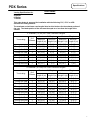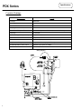
1
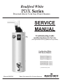
Bradford White
PDX Series
Powered Direct Vent Gas Water Heaters
SERVICE
MANUAL
Troubleshooting Guide
and Instructions for Service
(To be performed ONLY by qualified service providers)
For Bradford White
PDX Series Models:
PDX250T6*F(BN,CX)
PDX265T6*F(BN,CX)
PDX275T6*F(BN,CX)
PDX50S60F(B,C)*(N,X)
PDX65S65F(B,C)*(N,X)
PDX75S70F(B,C)*(N,X)
(*) Denotes Warranty Years
Manual 46925A
Save this manual for future reference
Bradford White
PDX Series
Powered Direct Vent Gas Water Heaters
Table of Contents
Page
TTW Service Procedure
Introduction
4
---
How to use this manual
5
---
Tool required for service
5
---
Specifications
6
---
Control Timings
8
---
Sequence of Operation
9
---
Troubleshooting
12
---
Burner Inspection, Cleaning and Replacement
14
I
Pilot Testing, Cleaning and Replacement
16
II
Pressure Switch Testing and Replacement
17
III
Blower Testing and Replacement
21
IV
Blower Temperature Switch Testing and Replacement
23
V
Gas Control & Thermal well Testing & Replacement
25
VI
Flammable Vapor Sensor Testing & Replacement
29
VII
Safety Circuit Voltage Trace
30
VIII
115VAC Circuit Trace
31
IX
Dip Tube inspection and Replacement
32
X
Anode Inspection and Replacement
33
XI
Flue Baffle Inspection and Replacement
34
XII
Inner Door Removal, Inspection & Replacement
35
XIII
Glossary of Terms
38
---
Parts List
39
---
Page 2
2
PDX Series
WARNING: If the information in these
instructions is not followed exactly, a fire or
explosion may result causing property damage,
personal injury, or death.
FOR YOUR SAFETY
Do not store or use gasoline or other
flammable, combustible, or corrosive vapors
and liquids in the vicinity of this or any other
appliance.
WHAT TO DO IF YOU SMELL GAS
Do not try to light any appliance.
Do not touch any electrical switch; do not use any
phone in your building.
Immediately call your gas supplier from a neighbor's
phone. Follow the gas supplier's instructions.
If you cannot reach your gas supplier, call the fire
department.
Installation and service must be performed by a qualified
installer, service agency or the gas supplier.
WARNING
Water heaters are heat producing appliances. To
avoid damage or injury, do not store materials
against the water heater or vent-air intake system.
Use proper care to avoid unnecessary contact
(especially by children) with the water heater and
vent-air intake components. UNDER NO
CIRCUMSTANCES MUST FLAMMABLE
MATERIALS, SUCH AS GASOLINE OR PAINT
THINNER BE USED OR STORED IN THE VICINITY
OF THIS WATER HEATER, VENT-AIR INTAKE
SYSTEM OR IN ANY LOCATION FROM WHICH
FUMES COULD REACH THE WATER HEATER
OR VENT-AIR INTAKE SYSTEM.
CAUTION
If sweat fittings are to be used DO NOT apply heat to
the nipples on top of the water heater. Sweat the
tubing to the adapter before fitting the adapter to the
water connections. It is imperative that heat is not
applied to the nipples containing a plastic liner.
WARNING
Hydrogen gas can be produced in an operating
water heater that has not had water drawn from the
tank for a long period of time (generally two weeks or
more). Hydrogen gas is extremely flammable. To
prevent the possibility of injury under these
conditions, we recommend the hot water faucet to be
open for several minutes at the kitchen sink before
you use any electrical appliance which is connected
to the hot water system. If hydrogen is present,
there will be an unusual sound such as air escaping
through the pipes as hot water begins to flow. Do
not smoke or have open flame near the faucet at the
time it is open.
CAUTION
Incorrect operation of this
appliance may create a hazard to
life and property and will nullify the
warranty.
DANGER
Do not store or use gasoline or
other flammable, combustible, or
corrosive vapors and liquids in the
vicinity of this or any other
appliance.
IMPORTANT
Before proceeding, please inspect the
water heater and its components for
possible damage. DO NOT install any
water heater with damaged
components. If damage is evident
then please contact the supplier where
the water heater was purchased or the
manufacturer listed on the rating plate
for replacement parts.
WARNING
DO NOT ATTEMPT TO LIGHT ANY GAS APPLIANCE
IF YOU ARE NOT CERTAIN OF THE FOLLOWING:
Liquefied petroleum gases/propane gas and
natural gas have an odorant added by the gas
supplier that aids in the detection of the gas.
Most people recognize this odor as a “sulfur” or
“rotten egg” smell.
Other conditions, such as “odorant fade” can
cause the odorant to diminish in intensity, or
”fade”, and not be as readily detectable.
If you have a diminished sense of smell, or are in
any way unsure of the presence of gas,
immediately contact your gas supplier from a
neighbor's telephone.
Gas detectors are available. Contact your gas
supplier, or plumbing professional, for more
information.
WARNING
FAILURE TO INSTALL AND MAINTAIN A NEW,
LISTED 3/4” X 3/4” TEMPERATURE AND PRESSURE
RELIEF VALVE WILL RELEASE THE
MANUFACTURER FROM ANY CLAIM THAT MIGHT
RESULT FROM EXCESSIVE TEMPERATURE AND
PRESSURES.
CAUTION
Turn off or disconnect the electrical power supply to the
water heater before servicing. Label all wires prior to
disconnection when servicing controls. Wiring errors
can cause improper and dangerous operation. Verify
proper operation after servicing.
Page 3
3
PDX Series
Introduction
The new Bradford White PDX2 and PDX water heaters are designed to provide reliable
performance with enhanced standard features. New design features include reliable spark to
pilot ignition system, enhanced diagnostics, simplified servicing, significantly quieter
operation, additional vent lengths and certified FVIR technology.
Spark to Pilot Ignition System - employing the spark to pilot ignition system promotes
reliable and consistent pilot and main burner ignitions to provide hot water on demand.
Integrated Immersion Thermostat/Gas Control Valve with LED - was developed for ease
of troubleshooting by providing simple diagnostic codes to pinpoint an installation or
component performance issue.
New Powerful Blower - will eliminate problems with difficult venting situations.
Quieter and Cooler Blower Operation - blower noise is significantly reduced for both
interior and exterior environments. Cooler operation increases blower life by reducing bearing
wear and noise.
Rugged Wiring Connections - receptacle type connections promote error free wiring.
Increased Vent Lengths - increased venting performance is achieved while maintaining
Energy Factor & FHSR performance.
The PDX2 and PDX water heaters use a combustion system were flue gases are combined with
dilution air to reduce the flue gas temperature in the blower, combustion air and dilution air are
drawn from outside the building. The diluted flue gases are evacuated to the exterior through
low temperature vent materials. The gas control maintains water temperature, ignition
sequence and regulates gas flow. A safety circuit consisting of a pressure switch and blower
temperature switch verifies proper conditions exist for safe and reliable operation. If a situation
outside of normal operating parameters exists, the gas control diagnostic LED will flash a code
to positively identify an operational issue.
This service manual is designed to facilitate problem diagnosis and enhance service efficiency.
To further promote quicker service times the new gas valve can be removed and replaced
without draining the water heater. A special tool is required and will be provided with each gas
valve kit shipped from our Service Parts department.
Please read the service manual completely before attempting service on this new series of
power vent models.
How the Safety System Works
During normal operation, air for combustion is drawn into the water heater though the vent pipe from outside your
building. The air travels into the closed combustion chamber. The air then mixes with in a normal manner with
supplied gas and its efficiently combusted, producing very low NOx emissions.
In the unlikely event trace amounts of flammable vapors are present in the area surrounding the water heater, the
sealed combustion system prevents the flammable vapors from reaching the ignition source. In addition the
flammable vapors sensor will stop the water heater from operating if a significant amount of flammable vapors are
present.
Page 4
4
PDX Series
How to Use This Manual
It is intended for this manual to be used by qualified service personal for the primary purpose of
troubleshooting and repair of the Bradford White TTW Series water heaters. Understanding the
sequence of operation section of this manual will contribute greatly to troubleshooting the water
heater.
The Honeywell WV4460E Electronic Gas Control will display error codes in the event of abnormal
operation. Error codes are listed in the troubleshooting chart beginning on page 12 of this service
manual. The troubleshooting chart will also indicate the probable cause for the error code and
direct the service professional to a service procedure to properly diagnose the abnormal operation.
In some difficult to diagnose conditions, it may be necessary to isolate the heater from the vent
system to determine the problem.
Contact the Bradford White technical support group immediately if diagnosis can not be made
using the methods described in this service manual.
Tools Required for Service
Manometer:
A liquid “U” tube type or a digital (magna-helic) type can be used. This
device is used to measure gas and/or air pressure and vacuum.
Multi-Meter:
A digital type is strongly recommended. This device is used to measure
electrical values. The meter you select must have the capability to
measure volts AC, volts DC, Amps, micro-amps and ohms.
Electronic Probes:
In some cases, standard multi-meter probes will damage or simply
not be effective to obtain certain voltage and ohm reading. It will be
necessary to have special electronic “pin” type multi-meter probes.
These probes are available at most electronic wholesale outlets.
Thermometer:
Used to measure water temperature. An accurate thermometer is
recommended.
Water Pressure Gage:
Used to measure water supply pressure. Also used to determine tank
pressure by adapting to the drain valve of the heater.
Gas Control Service Tool: BWC part number 239-45991-00. A specialized tool designed to remove
the gas control from gas control thermal well. Available from
your Bradford White parts supplier.
Various Hand Tools:
Pipe wrench, channel locks, open end wrenchs (3/8",7/16",½"),
12" crescent wrench, Allen wrench set, screw drivers (common &
Phillips), ¼" nut driver, pliers (common & needle nose), socket set, side
cutters wire cutters, wire strippers, wire crimpers, torpedo level, small
shop vac, step ladder, and flashlight, 5 gallon pail.
Page 5
5
PDX Series
Specifications
Power supply
Dedicated 115VAC, 60 Hz, 15A
Gas Supply Pipe
Minimum 1/2" NPT (schedule 40 black iron pipe recommended)
Approved Gas Type
Natural or Propane. Unit must match gas type supplied.
Gas Pressure
5.0" W.C. min. for Nat gas, 11.0" W.C. min. for L.P. gas, 14.0" W.C. maximum (Nat. & L.P.)
Venting System
Power vent through the wall or vertical through the roof
Approved Vent Materials
PVC, CPVC or ABS
Minimum Clearance
for Servicing
18" from top, 24" from front, 4" sides and rear.
Water Supply Pressure
150 PSI maximum allowable working pressure. Check local codes for supply pressure
Thermal well TCO Limit
Residential 188°F (87°C), Commercial 199°F (93°C)
Residential Temperature
60°F (16°C) to 160°F (71°C) (Approximate temperatures)
Set Point Range
Commercial Temperature
80°F (27°C) to 180°F (82°C) (Approximate temperatures)
Set Point Range
Blower Temperature
Switch
Pressure switch
Blower
Normally closed, opens @ 165°F (74°C), auto reset @ 130°F (54°C).
Exhaust-Normally open, closes on vacuum increase @ -1.30.
Intake-Normally closed, opens on vacuum increase @ -1.15.
115VAC, 60Hz, 3.1 amps.
Page 6
6
Specifications
PDX Series
Venting Specifications for:
Vent Tables
48 Gallon
65 Gallon
75 Gallon
This water heater is approved for installation with the following PVC, CPVC or ABS
Schedule 40 venting material.
The maximum and minimum vent lengths listed on this label are for the exhaust portion of
the vent. The intake portion of the vent must be equal to or less than the length of the
exhaust.
3" Diameter (7.6 cm) PVC Vent Connector Lengths
Maximum 48, 65 gal.
Maximum 75 gal.
Terminating
# of
Elbows
Through the Wall
Through the Wall
Through the Wall
Through the Wall
1
2
3
4
55 (16.8)
50 (15.2)
45 (13.7)
40 (12.2)
2 (.6)
2 (.6)
2 (.6)
2 (.6)
45 (13.7)
40 (12.2)
35 (10.7)
30 (9.1)
2 (.6)
2 (.6)
2 (.6)
2 (.6)
Through the Roof
Through the Roof
Through the Roof
Through the Roof
0
1
2
3
60 (18.3)
55 (16.8)
50 (15.2)
45 (13.7)
7 (2.1)
7 (2.1)
7 (2.1)
7 (2.1)
50 (15.2)
45 (13.7)
40 (12.2)
35 (10.7)
7 (2.1)
7 (2.1)
7 (2.1)
7 (2.1)
Maximum
Minimum
Maximum
Minimum
Length ft (m) Length ft (m) Length ft (m) Length ft (m)
4" Diameter (10.2 cm) PVC Vent Connector Lengths
Maximum 48, 65 gal.
Maximum 75 gal.
Terminating
# of
Elbows
Through the Wall
Through the Wall
Through the Wall
Through the Wall
Through the Wall
1
2
3
4
5
95 (29.0)
90 (27.4)
85 (25.9)
80 (24.4)
75 (22.9)
10 (3.1)
10 (3.1)
10 (3.1)
10 (3.1)
12 (3.6)
85 (25.9)
80 (24.4)
75 (22.9)
70 (21.3)
65 (19.8)
10 (3.1)
10 (3.1)
10 (3.1)
10 (3.1)
12 (3.6)
Through the Roof
Through the Roof
Through the Roof
Through the Roof
Through the Roof
0
1
2
3
4
100 (30.5)
95 (29.0)
90 (27.4)
85 (25.9)
80 (24.4)
15 (4.6)
15 (4.6)
15 (4.6)
15 (4.6)
15 (4.6)
90 (27.4)
85 (25.9)
80 (24.4)
75 (22.9)
70 (21.3)
15 (4.6)
15 (4.6)
15 (4.6)
15 (4.6)
15 (4.6)
Maximum
Minimum
Maximum
Minimum
Length ft (m) Length ft (m) Length ft (m) Length ft (m)
Page 7
7
Specifications
PDX Series
Control Timings
Ignition State
Timing
Pre-purge
2 Seconds
Trial for Ignition
90 Seconds
Flame Stabilization Period
3 Seconds
Inter-purge
15 Seconds
Flame Failure Response Time
1.5 Seconds (2 second. Maximum; 1 second minimum.)
Post-purge
15 Seconds
PS Fault Delay (failed open/close)
Retry after 2 Minutes
Soft Lockout
Retry after 5 Minutes
TCO Limit Lockout
Indefinite (cycle power to restart)
Verify Resistive Delay
Retry after 2 Minutes (repeats 5 times)
Simulated Resistive Load Lockout
Indefinite (cycle power to restart)
Hardware Error Lockout
Indefinite (self clears if fault clears for at least 15 seconds)
Wiring Diagram
Page 8
8
PDX Series
Sequence of Operation
Power up Sequence
1
Start Up.
Upon power up, the control runs a safe-start check with a typical start-up delay of 1-5 seconds.
2
Flammable Vapor Check.
To assure no outputs are energized if the “Flammable Vapor Sensor” is out of range, the control will test the
the “Flammable Vapor Sensor” for proper operating range. If the “Flammable Vapor Sensor” is within range the
control resumes normal operation with no perceptible delay. If the “Flammable Vapor Sensor” is out of range, the
control LED immediately flashes 7 times with 3 second pause.
Normal Heating Sequence
1
Thermostat calls for heat.
Prior to energizing blower, gas control checks safety circuit to insure the circuit is open. Normal switch positions
in the safety circuit are as follows:
a) Exhaust pressure switch normally open.
b) Blower temperature switch normally closed.
c) Inlet pressure switch normally closed.
If the safety circuit is closed, the control waits 4 seconds, gas control LED flashes 2 times with 3 second pause.
Gas control waits 2 minutes then, blower runs for 30 seconds. This cycle repeats until safety circuit opens.
2
Blower energizes.
3
Blower pre-purge period (2 seconds)
4
Exhaust pressure switch proves blower/vent system operation.
a) If the pressure switch does not close within 30 seconds, the control LED Flashes 3 times with 3 second pause.
The blower runs for 30 seconds every 2 minutes trying to get the pressure switch or blower temperature switch
to close. This cycle repeats as long as there is a call for heat.
b) The normally closed inlet pressure switch allows the system to work as long as the inlet air is not blocked.
5
Trial for pilot ignition (90 seconds).
a) The gas control lights the pilot by activating spark igniter and gas flow to pilot burner.
b) If flame is not sensed within 90 seconds, igniter and gas flow are deactivated, blower will post purge and
control LED flashes 6 times with 3 second pause.
6
Main burner Ignition
After pilot flame is sensed, gas control activates main valve for main burner ignition. The gas control will ignore
flame and pressure switch signals for 3 seconds allowing for main burner to stabilize.
Page 9
9
PDX Series
Sequence of Operation
Normal Heating Sequence (cont.)
7
Steady state operation.
During Steady State Operation the Control Monitors:
Thermostat temperature sensor- When set point temperature is satisfied, gas valve is shut down and
blower will post purge for 15 seconds. Control LED flashes a short flash once every 4 seconds (idle) status
code.
Pressure switch / Blower temperature switch- If either switch opens, pilot valve and main valve is shut
down. The blower continues to runs for 30 seconds attempting to close the circuit. The control LED Flashes
3 times with 3 second pause.
Flame Sense- If flame is lost, pilot & main valve are shut down, blower runs for 15 seconds. Control attempts
to re-light pilot 4 times. If unsuccessful, Blower is shut down and control proceeds to 5 minute lockout. Control
re-attempts to light pilot starting at normal heating sequence #2.
8
Thermostat satisfies.
9
Burner off.
10
Blower post purge (15 seconds).
Abnormal Operation
1. Simulated Resistive Device Fault:
a) If the Flammable Vapor Sensor resistance is greater than 70,000 Ohms - the gas control immediately turns
off all outputs. Control waits and monitors resistance for 30 seconds. If the resistance is greater than 70,000 ohms
after 30 seconds, the gas control proceeds to verify resistive delay for 2 minutes and flashes 7 times with a three
second pause. This process is repeated 5 times until the control either returns to normal operation or proceeds
to a lockout mode flashing 7 times with a 3 second pause.
b) If the Flammable Vapor Sensor resistance is below 3000 ohms - The gas control immediately turns off all
outputs and proceeds to flash 8 times then once with three second pause. The error self clears if the resistance
returns to normal range for at least 15 seconds.
2. Temperature Sensor Fault:
a) Temperature sensor detected open circuit - The gas control Immediately turns off all outputs and proceeds to
flash 8 times then three times with three second pause. The error self clears if the fault clears for at least 15
seconds.
b) Temperature sensors not reading the same temperature within ±5.5 °F - The gas control Immediately turns off
all outputs and proceeds to flash 8 times then three times with three second pause. The error self clears if the fault
clears for at least 15 seconds.
c) Water temperature in excess of TCO (Temperature Cut Off) limit - The gas control immediately turns off pilot &
main valve and proceeds to flash 4 times with 3 second pause. Blower continues to run until gas control is reset.
Power needs to be cycled to remove gas control from TCO lockout.
Page 10
10
PDX Series
Sequence of Operation
Abnormal Operation (cont.)
3. Pressure Switch/Blower Temperature Fault:
a) Pressure switch closed at start of call for heat - The control waits four seconds then, proceeds to flash
2 times with 3 second pause. The control waits 2 minutes and then turns on blower for 30 seconds. The blower
turns off after 30 seconds and the control waits for pressure switch to open. Any time the Pressure switch opens,
the blower turns on (or stays on) and the control proceeds to waiting for pressure switch to close.
b) Pressure switch or blower temperature switch failed open - The control runs the blower for 30 seconds
waiting for the pressure switch and/or blower temperature switch to close. If either switch does not close in 30
seconds, the blower turns off and the control flashes 3 times with 3 second pause. The control waits two
minutes before turning on the blower for another 30 seconds to see the circuit close. This cycle repeats as long as
there is a call for heat or until the circuit closes.
c) Pressure switch or blower temperature switch opens during burner operation - The control turns off the
pilot and main valve, runs blower for 15 seconds (inter-purge) waiting for pressure switch and/or blower
temperature switch to close. If either switch fails to close, the control proceeds as described in 3b above. If the
circuit closes again by the end of the inter-purge, the recycle counter is incremented, if the recycle count has
not reached its limit (4), another trial for ignition begins. If the recycle count has been reached, the control
turns off the blower and flashes 6 times then 2 times with 3 second pause. The control waits 5 minutes before
repeating ignition sequence.
d) Normally closed intake pressure switch opens at start of call for heat-the control runs the blower for 30
seconds waiting for the pressure switch to close. If the switch does not close in 30 seconds, the blower turns off
and the control flashes 3 times with a 3 second pause. The control waits two minutes before turning on the blower
for another 30 seconds to see the circuit close. This cycle repeats as long as there is a call for heat or until the
circuit closes.
4. Trial For Ignition Fault:
a) Pressure switch opens during trial - The control turns off igniter and pilot valve. The gas control proceeds
as described in 3b above. If the pressure switch closes within 30 seconds the gas control will continue with trial for
ignition starting at blower pre-purge.
b) Flame Not Sensed - The control energizes the spark igniter attempting to light the pilot and prove flame. If
flame is not sensed within 90 seconds, the igniter turns off, the pilot valve is closed and the gas control runs the
blower through post purge and flashes 6 times then once with 3 second pause. The control waits 5 minutes before
repeating the ignition sequence.
5. Flame Sensing Fault:
a) Flame lost during run - The control turns off pilot and main valves, runs blower for 15 seconds (inter purge).
The control increments the recycle count, if the recycle count has not reached its limit (4), another trial for
ignition begins. If the recycle count has been reached, the control turns off the blower and flashes 6 times
then 3 times with 3 second pause. The control waits 5 minutes before repeating the ignition sequence.
b) Flame sensed out of sequence - the control only looks for pilot flame when the blower is running. If flame is
present when the pilot valve is not open, the control proceeds to wait for flame loss and flashes 5 times with 3
second pause. This continues until flame is lost, once the flame signal is lost, the control flashes 6 times then 4
times with 3 second pause. The control waits 5 minutes before repeating the ignition sequence.
Page 11
11
Troubleshooting
PDX Series
Green LED
Indicator
Observe green LED indicator on
Electronic gas control. Error flash codes
are displayed with a three second pause
before repeating. Check and repair the
system as noted in the troubleshooting
table below.
LED Status
Control
Status
Probable Cause
None, control LED not
on or flashing
No electrical
power
Control power switch in “OFF” position.
Supply voltage interrupted.
Short flash, once every
four seconds
Stand-by mode,
Waiting for call for
heat (no fault).
Temperature demand is satisfied
“Heartbeat”, alternates
bright/dim
Thermostat calling
Tank temperature below set point of thermostat.
for heat (no fault).
Short flash once per
second
Weak pilot signal
on last call for
heat.
1. Unstable pilot.
2. Pilot tube block or restricted.
3. Oxidation build up on pilot electrode.
4. Wire damage to pilot assembly or bad
connection at gas valve.
Two flash, three
second pause
Pressure switch
not workingclosed position.
1. Pressure switch tubing kinked or blocked.
2. Blocked pressure tap on switch or blower.
3. Faulty pressure switch.
Three flash, three
second pause
1. Vent blockage or improper vent configuration.
2. Pressure switch tubing kinked or blocked.
Pressure switch
3. Faulty pressure switch.
or blower temp.
4. Blower not spinning up to speed.
switch not working
5. Blower temp or exhaust temp too high
-open position.
6. Faulty blower temperature switch.
7. Intake vent length exceeds exhaust vent length.
Service
Procedure
Turn power on
Normal operation.
Adjust thermostat to
temp level
Normal operation.
Adjust thermostat to
temp level
1. Page 14
2-4. Page 16
Page 17
1. Check vent or vent tables.
2 & 3 Page 17
4. Page 21
5 & 6 Page 23
Four flash, three
second pause
Excessive tank
temperature.
System must be
reset.
1. Thermal well sensor out of calibration.
2. Faulty gas control.
3. Plumbing leak
1. Page 25
Five flash, three
second pause
Undesired-false
pilot flame
present.
1. Pilot valve stuck in open position.
Replace gas control,
page 27
2. Replace gas control,
page 27
Page 12
12
Troubleshooting
PDX Series
LED Status
Control
Status
Six-one flash, three
second pause
Failed to light
pilot.
System auto
resets.
1. Unstable pilot.
2. Pilot tube blocked or restricted.
3. Oxidation build up on pilot electrode.
4. Wire damage to pilot assembly or bad
connection at gas valve.
Six-two flash, three
second pause
Pressure switch
or blower temp
switch opened
during burner
operation.
System auto
resets.
1. Vent blockage or improper vent configuration.
2. Pressure switch tubing kinked or blocked.
3. Faulty pressure switch.
4. Vent termination being affected by wind
5. Blower not spinning up to speed.
6. Blower temp or exhaust temp too high
7. Faulty blower temperature switch.
Six-three flash, three
second pause
Pilot flame
extinguished.
System auto
resets.
1. Unstable pilot.
2. Pilot tube blocked or restricted.
3. Oxidation build up on pilot electrode.
4. Wire damage to pilot assembly or bad
connection at gas valve.
5. Insufficient combustion air.
6. Gas pressure is out of specification.
Six-four flash, three
second pause
Undesired-false
pilot flame
sensed.
System auto
resets.
Pilot valve stuck in open position.
Seven flash, three
second pause
WARNING: EXPLOSION HAZARD
* Indicates gasoline vapors were detected at potentially
explosive levels.
Flammable Vapor
* Verify no gasoline vapors are still present
Sensor fault
* Reset the control by cycling power to the appliance or
detected
by cycling the ON/OFF switch.
* Replace the Flammable Vapors Sensor element if a
gasoline spill event occurred.
Page 29
Eight-one flash, three
second pause
* Verify Flammable Vapor Sensor (FVS) resistance is
Flammable Vapor
not below 25 K Ohms.
Sensor out of
* Check wiring to FVS and insure it is not shorted.
specification.
* Replace control if everything above checks out OK.
Page 29
Thermal well
sensor damaged
or unplugged
1. Damage to thermal well wire.
2. Thermal well sensor resistance out of range.
Page 25
Gas valve
electronics fault
detected
1. Control needs to be reset.
2. Control is wet or physically damaged.
1. Interrupt power supply
2. Replace gas control,
page 27
Gas valve fault
detected.
1. Control needs to be reset.
2. Control is wet or physically damaged.
1. Interrupt power supply
2. Replace gas control,
page 27
Eight-three flash, three
second pause
Eight-four flash, three
second pause
Probable Cause
Service
Procedure
1. Page 14
2-4. Page 16
1. Check vent or vent tables.
2 & 3 Page 17
4. Refer to venting section of
installation manual
5. Page 21
6 & 7 Page 23
1. Page 14
2-4. Page 16
5. Refer to installation manual
Replace gas control,
page 27
Page 13
13
PDX SERVICE PROCEDURE I
Burner Operation Inspection,
Adjustment, Cleaning and Replacement
PDX Series
Burner Inspection and Air Shutter Adjustment.
At periodic intervals (every 6 months) a visual inspection should be made of the pilot and main burner for proper
operation and to assure no debris is accumulating.
Pilot flame should be stable, some causes for an unstable pilot flame are:
a) Water heater vent is less than the allowable vent length.
b) Gas pressure is out of specification.
c) Pilot flame not fully engulfing spark/flame sensor.
Main burner should light smoothly from pilot and burn with a blue flame with a minimum of yellow tips.
Steel burner models self adjust air to gas ratio mixture and do not have an adjustable air shutter. Cast iron burner can
have the gas and air mixture properly proportioned by adjusting the air shutter on the mixer face of the main burner
(see cast iron burner adjustment below).
Main burner must be free from any debris accumulation that may effect burner operation (see burner cleaning
procedure on page 14).
Cast Iron Burner Air Shutter Adjustment
WARNING
Inner door and burner components may be HOT when performing this operation. Take
necessary precaution to prevent personal injury.
Step 1.
With main burner in operation, remove outer jacket door remove inner door as described in this manual,
see inner door removal, inspection and replacement section (page 35).
Step 2.
To adjust for proper burning, loosen the air shutter nut, rotate the air shutter to close the opening in the
burner, then slowly rotate the air shutter open until flame becomes as blue as possible with a minimum of
yellow tips. Tighten the air shutter nut.
Too much air will cause the flame to lift off the burner ports and create noisy burner operation.
Too little air will result in soot formation.
Step 3.
Replace inner door as described in this manual, observe burner operation. Burner should operate as
adjusted in step 2. If not, repeat air shutter adjustment compensating for proper burner operation with inner
door closed.
Air Shutter Nut
Air Shutter
Page 14
14
PDX SERVICE PROCEDURE I
Burner Operation Inspection,
Adjustment, Cleaning and Replacement
PDX Series
Burner Cleaning
Step 1.
Position gas control power switch to the “OFF” position and unplug heater from wall
outlet.
Step 2.
Turn off gas supply to water heater.
Step 3.
Remove outer jacket door and inner door per service procedure XIII on page 35.
Step 4.
Disconnect pilot tube (7/16 wrench) and
feedline (¾ wrench) from gas control.
Step 5.
Disconnect igniter/flame sensor wire from gas control.
Step 6.
Remove burner assembly from combustion chamber.
Step 7.
Thoroughly inspect burner surface area and burner port area and
remove any loose debris.
Step 8.
For cast iron burners, inspect for any debris build up inside
burner casting.
Igniter/flame
sense wire
Feedline nut
Pilot tubing nut
Burner
surface area
Burner
port area
Step 9.
Unscrew burner from main burner
orifice. On cast iron burners, loosen
air shutter nut and unscrew feedline
from burner.
Step 10.
Remove main burner orifice from
feedline (½" wrench on steel
burners, 3/8" wrench on cast iron)
inspect orifice, clean or replace if
necessary.
Reassemble burner and reinstall into water heater. Restore gas supply
and check for gas leaks.
Step 11.
Step 12
Main burner
orifice
L.P. Main burner
orifice. Left hand
thread
To resume operation follow the instruction located on the lighting
instruction label or the lighting instruction located in the installation
and operating manual.
Page 15
15
PDX Series
PDX SERVICE PROCEDURE II
Pilot testing, Cleaning and Replacement
Pilot Inspection, Testing and Replacement
Step 1.
Position gas control power switch to the “OFF” position and unplug heater from wall
outlet.
Step 2.
Turn off gas supply to water heater.
Step 3.
Remove outer jacket door and remove inner door per service proceedure XIII on page 35.
Igniter/flame
sense wire
Step 4.
Disconnect pilot tube nut (7/16 wrench) and feedline nut
(¾ wrench) from gas control.
Step 5.
Disconnect igniter/flame sense wire from gas control.
Step 6.
Remove burner assembly from combustion chamber.
Step 7.
Remove pilot assembly from feedline (¼" nut driver).
Step 8.
Visually inspect igniter/flame sense wire for damage. Replace
pilot if damage is found.
Step 9.
With a multi-meter set to the ohms setting, check continuity
through igniter/flame sense wire. Replace pilot if no continuity.
Step 10.
Visually inspect igniter/flame sense electrode for deterioration.
Replace pilot as necessary. Electrode should not be in contact
with pilot hood, If so, carefully adjust electrode to a gap
distance of 3/32" (.09) from pilot hood.
Step 11.
Visually inspect igniter/flame sense electrode for oxidation
build up. Carefully clean any oxidation using very fine emery
cloth.
Step 12.
Visually inspect pilot tubing for kinks or cracks. If damage is
found replace pilot.
Step 13.
Inspect pilot tubing and pilot orifice for blockage:
a) Remove ferrule nut from bottom of pilot assembly (7/16" wrench).
b) Remove pilot tube and pilot orifice.
c) Inspect pilot tubing and pilot orifice for blockage. Clean
or replace as necessary.
Step 14.
Reassemble pilot and install to feedline. Reinstall burner assembly to water heater. Restore gas supply
and check for gas leaks.
Step 15
To resume operation follow the instruction located on the lighting instruction label or the lighting
instruction located in the installation and operating manual.
Feedline nut
Pilot tubing nut
Ferrule
nut
Pilot
tubing
Igniter/flame
sense wire
Pilot
orifice
Pilot
hood
Igniter/flame
sense electrode
Page 16
16
PDX SERVICE PROCEDURE III
Pressure Switch Testing and
Replacement
PDX Series
Exhaust Pressure Switch
Testing
WARNING
120 volt potential exposure. Use caution
making voltage checks to avoid personal injury.
Step 1.
Position power switch on gas control
to the “OFF” position.
Step 2.
Remove the three screws (Phillips screw driver) from control access cover on blower assembly and
remove cover (see photo 1).
Step 3.
Remove tubing and wires from inlet pressure switch.
Step 4.
Carefully remove pressure switch from blower housing (see photo 2)
Exhaust
pressure switch
1
2
Inlet pressure
switch
Pressure Switch
Pressure switch
wire leads
With steps 1,2,3 & 4
complete,
disconnect wire leads from
pressure switch.
Use a multi-meter set to the
ohms setting. With blower off,
check across pressure
switch terminals.
Are switch contacts open?
(no electrical continuity)
Slide pressure switch in direction
of arrow while tilting slightly away
from blower housing.
Check tubing and pressure
tap on switch for blockage.
Is there blockage?
N
N
Replace switch
(see page 18)
Y
Y
Clear blockage
Position gas valve power
switch to the “ON” position
and adjust thermostat
to call for heat,
this will start the blower.
Check with multi-meter, do
pressure switch contacts
close with blower running
with the switch in the
vertical postition?
Y
Switch contacts are OK.
See safety circuit trace
(page 30)
Y
N
Check tubing and
pressure tap on
N
switch for blockage.
Is there blockage?
Y
Is vent
system
blocked
N
Is vent system length
within vent table
Y
specifications
listed on page 7
N
Reconfigure vent
system to be
compliant with
vent tables.
Y
See blower testing
(page 21)
Is blower OK?
N
Correct blower
problem.
Page 17
17
PDX SERVICE PROCEDURE III
Pressure Switch Testing and
Replacement
PDX Series
Exhaust Pressure Switch
Replacement
WARNING
120 volt potential exposure. Use caution
to avoid personal injury.
Step 1.
Position gas control power switch
to “OFF” position.
Step 2.
Remove the three screws (Phillips screw driver) from control access cover on blower assembly and
remove cover (see photo 3).
Step 3.
Disconnect the tubing and wires from inlet pressure switch.
Step 4.
Carefully remove pressure
switch from blower
housing (see photo 4)
Pressure Switch
4
3
Slide pressure switch in direction
of arrow while tilting slightly away
from blower housing.
5
Step 5.
Disconnect tubing from
pressure switch.
(see photo 5)
Step 6.
Disconnect yellow wires
from pressure switch
(see photo 6)
Step 7.
Reconnect wires from step 5 to new pressure switch.
Step 8.
Reconnect tubing to new pressure switch.
Step 9.
Carefully position pressure switch into blower housing.
Step 10.
Reconnect wires and tubing to inlet pressure switch.
Step 11.
Position gas control power switch to “ON” position and verify proper heater operation.
Step 12.
Replace control access cover from step 2.
6
Page 18
18
PDX SERVICE PROCEDURE III
Pressure Switch Testing and
Replacement
PDX Series
Inlet Pressure Switch
Testing
WARNING
120 volt potential exposure. Use caution
making voltage checks to avoid personal injury.
Step 1.
Position power switch on gas control
to the “OFF” position.
Step 2.
Remove the three screws (Phillips screw driver) from control access cover on blower assembly and
remove cover (see photo 7).
Step 3.
Remove wires from inlet pressure switch.
Exhaust
pressure switch
7
Inlet pressure
switch
Inlet pressure
switch wire
leads (found
inside cover)
With steps 1,2 & 3
complete.
Use a multi-meter set to the
ohms setting. With blower off,
check across pressure
switch terminals.
Are switch contacts closed?
Check tubing and pressure
tap on switch for blockage.
Is there blockage?
N
N
Replace switch
(see page 20)
Y
Y
Clear blockage
Position gas valve power
switch to the “ON” position
and adjust thermostat
to call for heat,
this will start the blower.
Check with multi-meter, do
pressure switch contacts
remain closed with blower
running with the switch in
the vertical postition?
Y
Switch contacts are OK.
See exhaust pressure
switch testing (page 17)
Y
N
Check tubing and
pressure tap on
N
switch for blockage.
Is there blockage?
Y
Is vent
system
blocked
N
Is vent system length
within vent table
Y
specifications
listed on page 7
N
Reconfigure vent
system to be
compliant with
vent tables.
Y
See blower testing
(page 21)
Is blower OK?
N
Correct blower
problem.
Page 19
19
PDX SERVICE PROCEDURE III
Pressure Switch Testing and
Replacement
PDX Series
Inlet Pressure Switch
Replacement
WARNING
120 volt potential exposure. Use caution
to avoid personal injury.
Step 1.
Position gas control power switch
to “OFF” position.
Step 2.
Remove the three screws (Phillips screw driver) from control access cover on blower assembly and
remove cover (see photo 8).
Step 3.
Disconnect the tubing from the pressure switch (see photo 9).
8
Step 4.
Remove inlet pressure
switch from blower access
cover. (see photo 10).
Step 5.
Disconnect yellow wires
from pressure switch (see
photo 11).
Step 6.
Attach new inlet pressure
switch to blower control
access cover.
Remove screws
to remove inlet
pressure switch
9
10
Step 7.
Reconnect wires from step 5 to new pressure switch.
Step 8.
Reconnect tubing to new pressure switch.
Step 9.
Replace control access cover from step 2.
Step 10.
Position gas control power switch to “ON” position and verify proper heater operation.
11
Page 20
20
PDX SERVICE PROCEDURE IV
Blower Testing and Replacement
PDX Series
WARNING
115 volt potential exposure. Use caution when
making voltage checks to avoid personal injury.
Blower Testing
Step 1.
Position gas control power switch
to “ON” position and adjust control to call for heat.
Step 2.
Remove the three screws (Phillips Screw driver)
from control access cover on blower assembly and
remove cover (see photo 12).
Does blower energize
Within 2 minutes?
Y
Disconnect vent
system from top of
blower and remove
exhaust vent
adapter.
(see photo 15)
Connect
manometer to
pressure tap of
blower.
(see photo 13)
Disconnect
pressure switch
tubing from blower.
(see photo 13)
N
14
Pressure tap
13
12
With blower running, and exhaust
adapter removed from top of
blower, is there a negative
pressure of -2.30" to -2.60" W.C.?
N
Pressure
switch tubing
N
Determine voltage
problem and correct.
Does blower energize after
2 minutes, run for 30
seconds and shut down?
Y
15
Remove exhaust
adapter
See pressure
switch testing
Page 17 & 19
Is there 115vac across
blue and green wires
(see photo 18)
16
Y
Y
Blower OK
Replace blower
17
N
Disconnect cord set
shown in photo 9. Is
there 115VAC across
terminals shown in
photo 16
Y
Incorrect supply
voltage polarity
N
Determine
power source
problem and
correct.
Y
Check power cord
for damage.
N
Replace blower
Y
N
N
Is there 115 VAC
at wall outlet?
Is there 115VAC
across terminals
shown in photo 17 ?
Y
Repair or replace
power cord
Replace
cord set
Reconnect cord set
shown in photo 9, is
there 115VAC between
blue wire and green
ground wire
(see photo 18)
N
Does cord set
N
have electrical
continuity?
Y
Replace blower
Green ground
wire
Y
18
Blue wire
Replace
gas control
Shown with pressure
switch removed.
Page 21
21
PDX SERVICE PROCEDURE IV
Blower Testing and Replacement
PDX Series
Blower removal
Remove exhaust
adapter and retain for
use on new blower.
Step 1.
Position gas control power switch to the “OFF” position.
Step 2.
Unplug blower power cord from wall outlet.
Step 3.
Disconnect vent system from exhaust adapter on top of
blower.
Step 4.
Remove exhaust adapter from blower (blade screw driver)
and retain for use on new blower
Step 5.
Unplug cord sets from blower.
Step 6.
Remove vertical air intake bracket.
Step 7.
Disconnect vertical air intake from blower.
Step 8.
Remove the three blower mounting screws
(¼" nut driver).
Step 9.
Remove blower with gasket from water heater.
Blower Mounting
Screws
Blower
Cord Sets
Vertical air intake
Vertical air intake
bracket
Blower Installation
Step 10.
Clean any debris from jacket head of water heater.
Step 11.
Set new blower with gasket in place using locating pins on
blower flange to line up with location holes in jacket head.
Be sure not to damage gasket.
Step 12.
Secure blower in place using mounting screws from step 8.
Step 13.
Slide vertical air intake tee onto blower.
Step 14.
Re-install vertical air intake bracket.
Step 15.
Re-install exhaust adapter from step 4.
Step 16.
Reconnect vent system to exhaust adapter.
Step 17.
Reconnect cord sets from step 5.
Step 18.
Plug blower power cord into wall outlet.
Step 19.
Position gas control power switch to the “ON” position.
Step 20.
Verify proper blower operation.
Locating Pins
on blower flange
Pin location holes in
jacket head
Page 22
22
PDX SERVICE PROCEDURE V
Blower Temperature Switch Testing
and Replacement
PDX Series
Blower Temperature Switch
Testing.
WARNING
120 volt potential exposure. Use caution
to avoid personal injury.
Step 1.
Position power switch on gas control
to the “OFF” position.
Step 2.
Remove tubing from inlet pressure tap.
Step 3.
Remove the three screws (Phillips screw driver) from
control access cover on blower and remove cover (see
photo 19).
Step 4.
Locate blower temperature switch (see photo 19)
19
20
Switch Setting
Opens on rise @ approximately 165°F
Auto resets on fall @ approximately 130°F
Blower temperature
switch location
Cool switch to
below 130°F
Air mixing inlet
Disconnect wire leads to
switch. Using a multi-meter
set to the ohms setting, is
there continuity between
the switch terminals?
N
Replace switch
(see page 24)
Y
Reconnect wire leads and
observe heater operation.
Do exhaust gas
temperatures rise to or
above 165°F?
N
Y
Do switch
contacts open?
N
Do switch
contacts open?
Y
Y
Exhaust
temperature is
too hot.
Common causes for
high exhaust temperature
1. Vent length is below minimum allowable.
2. Vent diameter not to specification.
3. Restricted dilution air inlet.
4. Missing or deteriorated flue baffle.
5. Gas pressure is out of specification.
Replace switch
(see page 23)
N
Switch OK
Page 23
23
PDX SERVICE PROCEDURE V
Blower Temperature Switch Testing
and Replacement
PDX Series
Blower Temperature Switch
Replacement.
WARNING
120 volt potential exposure. Use caution
to avoid personal injury.
Step 1.
Position gas control power switch to the “OFF” position
and unplug heater from wall outlet.
Step 2.
Remove tubing from inlet pressure tap.
Step 3.
Remove the three screws (Phillips screw driver) from the
control access cover on blower and remove cover.
(see photo 20)
Step 4.
Locate blower temperature switch (see photo 21)
Step 5.
Disconnect red and yellow wire leads from switch.
Step 6.
With an appropriate tool such as side cutters, snip the
retaining lug from the blower housing to allow removal of
temperature switch (see photo 22).
Step 7.
Remove switch from blower housing.
Step 8.
Install new switch. Be sure switch is properly seated in
mounting area.
Step 9.
Reconnect red and yellows wires to new switch. Wires are
interchangeable with either terminal.
Step 10.
Position gas control power switch to the “ON” position
and verify proper heater operation.
Step 11.
Replace control access cover from step 2.
20
21
22
Blower temperature
switch location
Snip retaining lug
from blower housing
Page 24
24
PDX SERVICE PROCEDURE VI
Gas Control/Thermal Well Testing and
Replacement
PDX Series
Gas Control Testing
See pages 27 & 28 for gas control
input & output testing.
Thermal Well Testing
Disconnect thermal
well wire harness
If Control has gone into TCO lockout due to
excessive tank temperature (four flash, 3 second
pause) reset control by rotating knob of temperature
control to the minimum setting for at least 6 seconds
before returning to desired temperature setting.
Observe heater operation. If control
continues to lockout due to
excessive tank temperature,
proceed to thermal well testing to
determine cause.
19
Thermal well testing
Position gas control power switch to
the “OFF” position and disconnect
thermal well harness from gas
control.
Using a multi-meter set to the
Ohms setting, determine the
resistance of thermal well sensor
(see caution photos 23 & 24)
20
CAUTION
DO NOT use standard multimeter probes for this test.
Doing so will damage connector. Use special pin type
electronic probes or small diameter wire pins inserted
into connector.
Using a multi-meter set to the ohms setting, insert one meter probe (see caution)
into center wire position of thermal well connector, insert the second probe (see
caution) into either of the outside wire positions (see photo 23).
Alternate the probe on the outside position to the opposite outside wire position
(see photo 24).
Once the thermal well resistance values are known, the water
temperature must also be known to determine if the resistance
values are correct. See page 25 to obtain water temperature.
N
Replace thermal well
(see page 27)
Are thermal well resistance values correct?
Y
Replace gas control
(see page 27)
Page 25
25
PDX SERVICE PROCEDURE VI
Gas Control/Thermal Well Testing and
Replacement
PDX Series
WARNING
Stored water may be HOT when performing the following steps in this procedure.
Take necessary precaution to prevent personal injury.
Determine Water Temperature Inside Tank
Note: It is important to understand once the resistance for the thermal well is determined from page 25, water flow
through the heater should not occur. Prior to performing the steps below, turn off the cold water supply to the
water heater. This will prevent cold water flow into the tank affecting the resistance value of thermal well.
Step 1.
Position gas control power switch to “OFF” position.
Step 2.
Draw approximately 4 gallons of water from drain valve into a container and discard. Draw an
additional gallon and immediately measure water temperature using an accurate thermometer. It may
be necessary to open a hot water faucet to allow heater to drain.
Step 3.
Using the chart below, determine correct resistance value for the water temperature from step 2.
Example:
If temperature of water is 84°F, then the resistance through the sensor would be
8449 (see shaded area). NOTE: Sensor resistance increases as the temperature
falls.
Sensor Resistance at Various Temperatures
°F
40
50
60
70
80
90
100
110
120
130
140
150
160
170
180
190
200
0
26109
19906
15314
11884
9299
7333
5827
4663
3758
3048
2488
2043
1688
1402
1170
982
828
1
25400
19383
14925
11592
9078
7165
5697
4562
3679
2986
2439
2004
1656
1376
1150
965
814
2
24712
18876
14548
11308
8862
7000
5570
4464
3602
2925
2391
1966
1625
1351
1129
949
801
3
24045
18383
14180
11032
8653
6839
5446
4368
3527
2866
2344
1928
1595
1327
1110
933
788
In Degrees
4
23399
17905
13823
10763
8449
6683
5326
4274
3453
2808
2298
1891
1566
1303
1090
917
775
F
5
22771
17440
13477
10502
8250
6531
5208
4183
3382
2752
2253
1856
1537
1280
1071
901
762
6
22163
16990
13140
10248
8057
6383
5094
4094
3312
2697
2209
1820
1509
1257
1953
886
749
7
21573
16553
12812
1000
7869
6238
4982
4006
3244
2643
2166
1786
1481
1235
1035
871
737
8
21000
16128
12494
9760
7685
6098
4873
3922
3177
2590
2124
1753
1454
1213
1017
857
725
9
20445
15715
12185
9526
7507
5961
4767
3839
3112
2538
2083
1720
1427
1191
999
842
713
Page 26
26
PDX SERVICE PROCEDURE VI
Gas Control & Thermal Well Testing
and Replacement
PDX Series
Gas Control & Thermal Well Removal From Water Heater
Gas Control
Step 1.
Position gas valve power switch to the “OFF”
position and Unplug Heater from power supply.
Step 2.
Drain heater to a point below the gas
control level.
Step 3.
Turn off gas supply to water heater and
disconnect gas piping from gas control.
Step 4.
Disconnect wire harnesses and burner assembly
from gas control.
Step 5.
Remove gas control & thermal well by rotating flats of Thermal Well counter clockwise (1-5/16"wrench).
Thermal
Well
Gas Control Removal From Thermal Well
Follow the steps below allows removal gas control from thermal well without
removing thermal well from tank.
Step 1.
Position gas control power switch to the “OFF” position and unplug water heater from power supply.
Step 2.
Turn off gas supply to water heater and disconnect gas piping from gas control.
Step 3.
Disconnect wire harnesses & burner assembly from gas control.
Step 4.
Using gas control service tool (239-45991-00) available from your BWC parts supplier, Insert tool into
back of gas control (see photos below)
View from back of
control for clarity
Insert tool from
back of control
Step 5.
Service tool shown
inserted in to back
of control
Pivot tool towards heater as far as possible (see photo below). Lift straight up on gas control. The
control should move about 1/8". Hold control in position and remove tool. Lift straight up on control to
remove completely from Thermal Well.
With service tool inserted, pivot tool back towards water
heater as far as possible. Lift straight up on control,
control will move 1/8". Remove tool and continue to lift
straight up on control to remove from Thermal Well.
Page 27
27
PDX SERVICE PROCEDURE VI
Gas Control & Thermal Well Testing
and Replacement
PDX Series
Gas Control Assembly to Thermal Well
Step 1.
Install threaded end of thermal well into tank. Be sure
thermal well flange is positioned as shown in photo 24
for proper control alignment.
Step 2.
Route wire leads back into relief opening.
(see photo 24)
Step 3.
Align slots located on thermal well flange with tabs
located on back of gas control (see photo 24 & 25)
24
Route wires
through relief
opening
Thermal well
flange slots
Step 4.
Carefully push control back onto thermal well flange
as far as possible towards water heater. Slide control
down to lock into position.
Step 5.
Install burner and connect pilot tubing and feedline nut
to gas control.
25
Gas control Tabs
Igniter/sensor
connection
Step 6.
Reconnect wire harnesses to gas control
per the illustration.
Step 7.
Reconnect gas piping to gas control.
Restore gas supply and check for gas
leaks.
Step 8.
To resume operation, follow the
instruction located on the lighting
instruction label or the lighting instruction
located in the installation and operation
manual.
Ground Wire
connection
5 pin
blower harness connection
3 pin
thermal well connection
Flammable Vapor
Sensor
Page 28
28
PDX SERVICE PROCEDURE VII
Flammable Vapors Sensor Testing
PDX Series
Flammable Vapor Device Testing
Step 1.
Position power switch on gas control to the
“OFF” position.
Step 2.
Disconnect flammable vapor sensor from
gas control.
Step 3.
Using a multi-meter set to the ohms setting
check resistance of flammable vapor sensor.
(see caution below)
Resistance must be within 3,000 ohms and
48,000 ohms. If outside of this range replace
flammable vapor sensor.
Flammable Vapor
Sensor
Multi-meter set to
ohms setting
Electronic
“pin type”
Meter Probes
CAUTION
DO NOT use standard multimeter probes for this test.
Doing so will damage connector. Use special electronic
“pin type” probes or small diameter wire pins inserted
into connector.
Flammable Vapor
Sensor
Page 29
29
PDX SERVICE PROCEDURE VIII
Safety Circuit Voltage Trace
PDX Series
Safety Circuit Voltage
Trace
WARNING
120 volt potential exposure. Use caution
making voltage checks to avoid personal injury.
NOTE: This procedure assumes a cool tank.
27
Step 2.
Remove three screws (Phillips Screw driver) from control
access cover on blower and remove cover (see photo 26).
Position gas control switch to the “ON”
position and adjust thermostat dial to call
for heat, Is there 10 to 13 VAC between
red wire leading to blower temperature N
switch and green ground wire?
Blower must be running during this
voltage check.
(see photo 28)
Y
Is LED on gas valve flashing
Y
the “heartbeat” code
(alternating bright/dim)
N
Verify 120VAC to gas
control (see page 30)
Is there 10 to 13 VAC between yellow
wire leading from pressure switch and
green ground wire?
(see photo 28)
Is there continuity
through blower
temperature switch?
(see page 21)
N
Check for loose or
broken wire
connection at switch
terminals
Determine cause of blower
temperature switch
activation and correct.
Correct igniter/
sensor problem.
N
Check igniter/sensor
(see page 16)
is igniter/sensor OK?
Y
Safety circuit
voltage is OK.
Y
N
Y
Do you hear or can you
see the igniter sparking?
No voltage from gas control,
call for technical support.
Y
Faulty cord set or
gas control.
Green ground wire
28
Red wire leading to
blower temp. switch
If burner does not light,
observe LED flash code
on gas valve and refer to
troubleshooting section
on page 12
Yellow wire
leading from
pressure switch
Page 30
30
PDX SERVICE PROCEDURE IX
120 VAC Trace
PDX Series
WARNING
120 volt potential exposure. Use caution
making voltage checks to avoid personal injury.
120 VAC Circuit Trace
Step 1. Verify 120VAC and proper polarity at wall outlet.
Step 2. With unit plugged in and control power switch in the “ON” position verify LED status.
LED status
None, Control LED not
on or flashing.
LED status
Short flash, once every
four seconds.
LED status
“Heartbeat”, alternates
bright/dim.
LED status
Various flashing error
codes.
Waiting for
call for heat.
Thermostat calling
for heat
Verify error code as
listed on page 12
30
29
31
Disconnect cord set as
shown in photo 29
Using a volt meter set
to volts AC, is there
120VAC across
terminals shown in
photo 30 ?
Check for damage to Y
AC supply power cord.
N
N
Y
Is there 120VAC
across terminals
shown in photo 31 ?
Repair damage
Replace Blower
Y
Reconnect cord set
shown in photo 29.
32
N
Disconnect wire harness
from gas control
(see photo 32).
Incorrect supply
voltage polarity
Wire harness
Locate black & white wires at
connector, It may be necessary to pull
back wire sheath to identify wire colors.
(see photo 33)
33
Wire sheath pulled back to
identify wire colors
Is there 120VAC
across black & white
wires as shown in
photo 33?
N
Y
Replace gas
control.
Check for 120VAC between black & white wires.
-NOTEElectronic meter probes required. Use care not to
damage connector during this check.
Call for technical
support.
Page 31
31
PDX Series
PDX SERVICE PROCEDURE X
Dip Tube
Inspection and replacement
Dip Tube Inspection and Replacement
WARNING
Water Heater components and stored water may be HOT when performing the following
steps in this procedure. Take necessary precaution to prevent personal injury.
Step 1.
Position on/off switch of gas control valve to “OFF” position and unplug water heater from wall outlet.
Step 2.
Turn off cold water supply to water heater. Connect hose to drain valve of water heater and route to an
open drain. Open a nearby hot water faucet to vent heater for draining. Open drain valve of water
heater and allow heater to drain to a point below the inlet connection nipple.
Step 3.
Disconnect inlet nipple from plumbing system.
Step 4
With an appropriate tool such as a pipe wrench, remove inlet nipple/dip tube from the water heater.
Use caution not to damage pipe threads.
Step 5.
Visually inspect inlet nipple/dip tube. Inlet nipple/dip tube should be free of cracks and any blockage.
Hydro-jet slots should be open and free of any blockage.
Any damage such as cracks, restriction due to deformation or unintentional holes are not field
repairable and the inlet nipple/dip tube must be replaced.
Step 6.
Upon completion of inspection or subsequent replacement, reinstall inlet nipple/dip tube into water
heater. Connect nipple to plumbing system, resume water supply and refill with water.
Step 7.
To resume operation follow the instructions located on the lighting instruction label or the lighting
instructions located in the installation and operation manual.
Page 32
32
PDX Series
PDX SERVICE PROCEDURE XI
Anode
Inspection and replacement
Anode Inspection and Replacement
WARNING
Water Heater components and stored water may be HOT when performing the following
steps in this procedure. Take necessary precaution to prevent personal injury.
Step 1.
Position on/off switch of gas control valve to the “OFF” position and unplug water heater from wall
outlet.
Step 2.
Turn off cold water supply to water heater. Connect hose to drain valve of water heater and route to an
open drain. Open a nearby hot water faucet to vent water heater for draining. Open drain valve of
water heater and allow water heater to drain to a point below the outlet connection nipple.
Step 3.
Disconnect outlet nipple from plumbing system.
Step 4
With an appropriate tool such as a pipe wrench, remove outlet nipple/anode from the water heater. Use
caution not to damage pipe threads.
Step 5.
Visually inspect outlet nipple/anode. Outlet nipple/anode should show signs of depletion, this is
normal. If depletion is ½ of the original anode diameter (approximately ¾” diameter), replacement is
recommended. If any of the steel core of the anode is exposed, replacement is recommended.
Step 6.
Upon completion of inspection or subsequent replacement, reinstall outlet nipple/anode into water
heater. Connect nipple to plumbing system, resume water supply and refill with water.
Step 7.
To resume operation, follow the instructions located on the lighting instruction label or the lighting
instructions located in the installation and operation manual.
Page 33
33
PDX SERVICE PROCEDURE XII
Flue Baffle
Inspection and replacement
PDX Series
Remove blower to gain access to
flue baffle
Disconnect vent
system from exhaust
adapter.
Step 1.
Position gas control power switch to the “OFF” position and
unplug blower from wall outlet.
Step 2.
Disconnect vent system from exhaust adapter on top of blower.
Step 3.
Disconnect intake air piping.
Step 4.
Unplug cord sets from blower. (see photo 34).
Step 5.
Remove the three blower mounting screws
(¼" nut driver) (see photo 34).
Step 6.
Remove blower with gasket from water heater.
Step 7.
Remove flue baffle from Heater (see photo 36).
Step 8.
Inspect baffle for deterioration, missing restrictors.
Clean any scale or debris build up. Replace with new baffle as
necessary.
Step 9.
Reinstall baffle into flue tube. Be sure baffle
hanger tabs are inserted into notch location at the
top of the flue tube (see photos 36 & 37).
34
Blower Mounting
Screws
Blower
Cord Sets
Step 10.
Check Burner to insure no scale has accumulated during this
operation. See burner cleaning procedure on page 15.
Step 11.
Reinstall blower on water heater. Connect vent
system and cords set to blower. Plug water heater
into wall outlet.
Step 12.
To resume operation follow the lighting instruction
located on the lighting instruction label or the lighting instruction
located in the installation and operation
manual.
35
Remove support
bracket
36
Flue Baffle
37
38
Baffle shown
installed in flue
tube notch.
Flue tube
notch
Page 34
34
PDX Series
PDX SERVICE PROCEDURE XIII
Inner Door/Gasket Removal, Inspection
Replacement and Reinstallation
Inner Door Removal Procedure.
Step 1. Slide switch of the Electronic Gas Control to the “OFF” position and unplug from wall.
Step 2. Remove outer jacket burner access door.
Step 3. Disconnect wire connections from Electronic Gas Control.
Step 4. Right side Inner Door Removal.
a) Remove wire tie from feedline.
b) Remove (2) 1/4" hex drive screws from right side inner door.
c) Remove (2) 1/4" hex drive screws from flange section of inner door.
d) Remove right side inner door and set aside. Be careful not to damage gasket material on inner door.
¼" Hex Drive Screws shown on
Right Side Inner Door.
¼" Hex Drive Screws at
Flange section of Inner Door
Step 4. Fully inspect inner door gaskets for the following:
>Tears
>Other imperfection that will inhibit proper seal
>Missing Material
>Gasket adhesion to inner door
>Cracks
>Material left on combustion chamber (around opening)
>Dirt or debris
If the gasket is not effected by any of the above, gasket replacement is not required. If replacement is required,
proceed to Inner Door Gasket Replacement Procedure.
Inner Door Gasket Replacement Procedure.
WARNING
If the information in these instructions is not
followed exactly, a fire or explosion may result causing
property damage, personal injury or death.
Step 5.
After inspection of inner door as noted in step 4, completely remove gasket and adhesive residue from right
and left side inner doors as needed.
Step 6.
Use RTV sealant (recommended bead size is 1/8") to secure the inner door gasket to the inner door sections
(right & left). Refer to illustration below for proper application. Note the overlap configuration in the flange
area of the inner door. Set the flange section first, this will help to achieve the proper over lap position.
Page 35
35
PDX Series
Installation of Inner Door With Gasket.
Step 7.
Clean any residual gasket residue or other debris
from combustion chamber surface before installing
the inner door/gasket assembly.
Step 8.
Place the left side inner door into position first.
Firmly position the radiused channel of the inner
door aroundthe feedline. Using the 1/4” hex drive
screws from step 3d, secure left side inner door in
place. DO NOT OVER TIGHTEN SCREWS.
Step 9
Position thermocouple, pilot tube and Piezo wire
against left side inner door flange gasket. DO
NOT ROUTE THROUGH RADIUSED
CHANNEL WITH FEEDLINE.
PDX SERVICE PROCEDURE XIII
Inner Door/Gasket Removal, Inspection
Replacement and Reinstallation
WARNING
Stripped fastener connections may allow
for seal breach of inner door. A seal
breach may result in a fire or explosion
causing property damage, personal
injury or death. Do not over tighten
screws in steps 8, 10 and 11.
If a fastener connection is stripped,
contact the manufacturer listed on the
water heater rating plate.
Igniter wire and pilot tube
shown in proper position.
Radiused Channel
for Feedline
Page 36
36
PDX Series
PDX SERVICE PROCEDURE XIII
Inner Door/Gasket Removal, Inspection
Replacement and Reinstallation
Installation of inner door with gasket (continued from page 36).
Step 10.
Firmly place right side inner door flange against the left side inner door flange and secure with two ¼” drive
screws from step 3c. DO NOT OVER TIGHTEN SCREWS.
Step 11.
Align right side inner door to combustion chamber and verify the fastener holes of the combustion
chamber are aligned with the right side inner door slotted opening. Verify seal integrity around combustion
opening. Secure right side inner door using 1/4” hex drive screws from step 3b. DO NOT OVER TIGHTEN
SCREWS. Verify both left and right sides of the inner door are properly positioned and sealed against the
combustion chamber
Verify threaded hole
alignment with slotted
openings in inner door.
Step 12.
Replace outer jacket burner access door.
Step 13.
To resume operation follow the instructions located on the lighting instruction label or the lighting instructions
located in the installation and operation manual.
Page 37
37
PDX Series
BTU
GPM
Hz
KW/h
LED
NPT
Ohms
PSI
RPM
TCO
VAC
W.C.
°C
°F
Glossary of Terms
British Thermal Units
Gallons per Minute
Hertz
Killo-watts per hour
Light Emitting Diode
National Pipe Thread
Ohms of resistance
Pounds per Square Inch
Revolutions per Minute
Temperature Cut Off
Volts Alternating Current
Inches of Water Column
Degrees Centigrade
Degrees Fahrenheit
NOTES
Page 38
38
Parts List
PDX Series
1. Blower Assembly
2. Blower Temp. Switch
3. Exhaust Pressure Switch
4. Inlet Pressure Switch
5. Blower Gasket
6. Tee and Vent Pipe Assy.
7. Vent Adapter with Term.
8. Intake Terminal
9. Vent Terminal Elbow
10. Exhaust Adapter
11. Condensate Hose Kit
12. Flue Reducer
13. Heat Trap Insert (outlet)
14. Heat Trap Insert (inlet)
15. Hot Water Outlet Anode
16. Cold Water Inlet Diptube
17. Flue Baffle
18. Blower Harness
19. T&P Relief Valve
20. ¾ NPT PLUg
21. Direct Vent Boot
Escutcheon
22. Air Intake Boot
23. Air Intake Boot Gasket
24. Outer Door
25. Right Side Inner Door
26. Left Side Inner Door
27. Screw-#10-12 x ¾ HWH
28. Screw-#8-18 x ¾ HWH
29. Brass Drain Valve
30. Flammable Vapor Sensor
31. Sensor Harness
32. Flammable Vapor Sensor
Clip
33. Thermal Well
34. Gas Control Kit
35. Gas Control Service tool
36. Gas Control
37. Gas Burner Assy (Nat.)
38. Gas BN burner (Nat.)
39. Main Burner Orifice (Nat.)
40. Gas Pilot Assembly (Nat.)
41. Gas Pilot Orifice (Nat.)
42. Gas Feedline (Nat.)
43. Gas Burner Assy (L.P.)
44. Cast Iron Burner (L.P.)
45. Gas Pilot Assy (L.P.)
46. Gas Pilot Orifice (L.P.)
47. Air Shutter (L.P.)
48. LP Gas Feedline (L.P.)
49. Air Shutter Nut (L.P.)
50. Main Burner Orifice (L.P.)
51. Inner Door Gasket
52. Heat Trap Insert kit
53. Mixing Valve
Page 39
39
Email
[email protected]
[email protected]
www.bradfordwhite.com