1
Vlrcstrx
00イ
Vestax Mixing cOnirO!ler
取 扱 説 明 書
P,2∼
OWNEREs MANUAL
P.14∼
Veslax Corporation
1-1$5 Wal6bayashl, Setagaya-hl, Tokyo lsIHDA Japan
Pione (P0412-7011 Fil (F34!2-m13
〒 154● 023
果宗郵世田谷 区若林 卜 18‐ 6
フアックス 03‐ 3412‐ 7013
電話 03-34¬ 2‐ フ011
Web:―
.vestax.com
Web
:
wwu,ves'tax.corn
Vestax Europe Technical SuPPort
Fhelns!213 D5ilililz Bomhelm Cietmany
Plwtg 49{i0@-9$ah7i2 Far 49l0lE2,24$.*7 4
CONGRATULAT10NS!
Thank you for purchasing the Vestax VMC-OO4FXu Mixing Controller. We suggest
that you read through this owner's manual thoroughly so that you may enjoy the full
use of this product safety and in the knowledge of all its special features and
suitably applications.
CONTENTS
C A U tt 1 0 N
IMPORTANT SAFEGUARDS
FE AttU R E S
CONTROLS AND FUNCTIONS
TOP PANEL
FRONT PANEL
REAR PANEL
ABOUT ttHE EFFECTS
‐
………………………………………………………………… 14
………………………………………………………………… 15
-… …………………………―……………………………… 16
‐
………………………………………………………………… 17
…………………………… …………………………………… 17
……………………………………………………………………18
…………………………………………………………………… 19
………… ……………………………… ……… ……… …………‐
―………………20
HOWTO CHANGETHE FADER UNIT -… …………… ………………………………………… ……‐ ―…… ………… 25
CONNECT10N DIAGRAM ………… … ………………………… …………………… …………… ……… 26
SPECIFICA丁 10NS ………………………………………………………………―…………………‐……………27
△△
CAUT10N:丁 O REDUCE THE RISK OF ELttCTRiC SHOCK
DO NOT REMOVE COVER(OR BACK)
NO USER― SERVICEABLE PARTS INSiDE
REFER SttRViCING TO QUALIFl匡 D SERV!CE PERSONNEL
The lightning flash with arrowhead symbol, within an equilateral triangle, is
intended to alert the user to the presence of uninsulated "dangerous voltage"
within the product's enclosure that may be of sufficient magnitude to consitute
risk of electric shock to persons..
a
The exclamation point within an equilateral triangle is intended to alert the user
to the presence of important operating and maintenance (servicing) instructions
in the literatufe accbstpanyin!- the appliance.
TO R[DUCE THE RISK OF FIRE OR ELECTRIC SHOCK, DO NOT
巨XPOSE THIS APPLIANCE TO RAIN OR MOISttURE.
‐
14‐
lMPORttANtt SAFEGUARDS
READ BEFORE OPERATING EQUIPMENT
This product was designed and manufactured to meet strict quality and safety
standards. There are, however, some installalion and operation precautions
which you should be particularly aware of.
1.Read instructions-All the safety and operating
instructions should
be read before
the
appliance is operated.
2.Retain instructions-The safety and operating
instructions should be retained for future
reference.
3.Heed Warnings-All warnings on the appliance
and in the operating instructions should be
adhered to.
4.Follow Instructions-All operating and use
9.This product should never be placed near or
over a radiator or heat register. This product
should not be placed in a built-in installation
such as a bookcase or rack unless proper
ventilation is provided or the manufacturer's
instructions have been adhered to.
10.Power sources-This product should be
operated only from the type of power source
indicated on the marking label. lf you are not
sure of the type of power supply to your
home, consult your appliance dealer or local
power company.
instructions should be followed.
5.Cleaning-Do not use liquid cleaners or
aerosol cleaners. Use a damp cloth for
of this
product during a lightning storm, or when it is
left unattended and unused for long periods
of time, unplug it from the wall outlet. This will
prevent damage to the product due to
lightning and power-line surges.
l l.Lightning-For added protection
cleaning.
6.Attachments-Do not use attachments not
recommended by the product manufacturer
l2.Overloading-Do not overload wall outlets
and extension cords as this can result in a
as they may cause hazards.
T,Water and Moisture-Do not use this product
near water-for example, near a bath tub,
wash bowl, kitchen sink, or laundry tub, in a
wet basement, or near a swimming pool, and
the like.
S.Accessories-Do not place this product on an
unstable cart, stand, tripod, or table. The
product may fall, causing serious injury to a
child or adult, and serious damage to the
appliance. Use only with a cart,. stand,
tripod, bracket, or table recommended by the
manufacturer, or sold with product. Any
mounting of the appliance should follow the
manufacturer's instructions, and should use a
mounting accessory recommended by the
manufacturer.
risk of fire or electric shock.
13.Object and Liquid Entry-Never push objects
of any kind into this product through
openings as they may touch dangerous
voltage points or short-out parts that could
result in a fire or electric shock. Never spill
liquid of any kind on the product.
14.Servicing-Do not attempt to service product
yourself as opening or removing covers may
expose you to dangerous voltage or other
hazards. Refer all servicing to qualified
personnel.
-15-
15.Damage Requiring Service-Unplug this
product from the wall outlet and refer
servicing to qualified service personnel under
the following conditions:
a.When the power-supply cord or plug is
l6.Replacement Parts-When replacement
parts are required, be sure the service
technician has used replacement parts
specilied by the manufacturer or have the
same characteristics as the original parts.
Unauthorized substitutions may result in fire,
electric shock or other hazards.
damaged.
b.lf liquid has been spilled or objects have
fallen into the product.
c.lf the product has been exposed to rain or
water.
d.lf the product dose not operale normally by
following the operating instructions. Adjust
only those controls that are coverd by the
operating instructions as an improper
adjustment of other, controls may result in
damage and will often require extensive
work by a qualified technician to restore the
product to its normal operation.
e.lf the product has been dropped or cabinet
has been damaged.
f. When the product exhibits a distinct change
in performance this indicates need for
17.Safety Check-Upon completion of any
service or repairs to product, ask the service
technician to perform safety checks to
determine that the product is in proper
operating condition.
18.Carts and Stands-The appliance should be
used only with
a cart stand that is
recommended by manufacturer.
19.An appliance and cart combination should
be moved with care. Quick stops, excessive
force, and uneven surfaces may cause the
appliance and cart combination to overturn.
service.
FEATURES
OEffects are assignable separately to the master
section and A & B side of the crossfader.
Easily selectable with the effect assign switch.
OOriginal algorithm developed so that each
effect parameter is adjustable with simple
operation.
On
High-grade 24biv96kHz Digital Sound
Processor (DSP) has been applied to the
VMC-004FXu for better sound quality and less
latency.
OOigitat connection with computers and USB
devices is enabled by installing TUB-1(USB
Board / Sold Separately)to the OPTION
BOARD slot.
OThe TAP button is used to set the delay time
and LFO rate,simply by tapping the button. The
inputted tempo can be switched to 1/4,1/2,3/4
and double of the original tempo instantly with
- to-
the beat select switches.
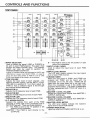
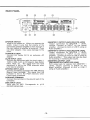
CONttROLS AND FUNC丁10NS
PGM 2
PCM l
一
一
1
」 出 … こ (EDい
に1
1“
3o口
●2
PCM 3
粧
,ho∞
01"`
1:101
′
=慮
五
PCM 4
201"`
⊇
[:1≪
≫
⊂
lm
勇盤
4
日
E■ b cia539n
。C i a8819n
■
=コ
口
。 c,aSSion
① INPUT
SELECTOR
・The
B・・
Used to select the signal(LiNE or PHONO)to
be sentto each PGM channel.The upper rnost
② lNPUT
switch can a:so be used to perform for
USB(Oplcnal, please read REAR PANEL on page19)
③ CROSS
5/USB,both signals wi‖ be mixed in to the channel.
VOLUME
heard with the cross fader set to the right side.
When the crossfader is set in the center, both
the channel without distorting.
MID
AdiustS the M:D frequency level of each PGM.
⑤ :SOLATOR
LOW
AdiustS the LOW frequency level of each PGM.
⑥C.F.ASSIGN
FADER
鵬驀響報 職瑚 鶏1種
『
椰灘『轟聯鰤轟
AdiustS the H:frequency level of each PGM.
LEVEL METER
The LED level rneters indicate the input signal
level of each PGM channel.
and r the input select switch of PGM 3 is set to LINE
④iSOLATOR
LEVEL FADER
channel.
③ :NPUT
※When 2 individuaiinputs are connected to L:NE 5 and
Hl
PGM is sentto the"B"position or right
Used to adiuSt the input level of each PGM
TRANSFORMER SCRATCH.
③ ISOLATOR
(⊂
side ofthe crossfader.
posilon wili select PHONO input. This selector
② TRIM
鮎鵡
一一
¨
一
一
判
競 攣。
器 郷
郡
worn out.
笙 :点 :鷲 %:」
叫
3諸 U8F訛
絆
憎
⑩ MASTER
l LEVEL VOLUME
mpdS mm MASTER l
劉 ギ L縄 繰
出
① MASTER 2 LEVEL VOLUME
鵠 竿書LttLttVd°
SWITCH
'° uゃ uじ frOm MASTER l
LEVEL METER
:s鑑 a貯 肥⑫ MASTER
論総 stti譜 竃
L」 Thξ 雷
The LED level meters indicate the masterЭ
signallevei of each PGM cannel.
RIWヽ鶉ぎL課 l『「a::it
S貯dЮ :'電 貴OPOWER
iNDICATOR
Llghts up whenthe POWER SWITCH ⑩ is On.
e
ttyわ 油
MASttTPtthFさ 需
誕 =木
:「
OUTPUTS.
‐
17-
⑭ CUE
CHANNEL SELECT SWiTCH
ht調 iPh型 ::l淵 :ξ
静摺猟
ilζ .ξ
⑮ MON]TOR
l誦
鐵番
④Depthrsweep volume
lume adiuStS the depth/sweep of each
Thi勇
MIX VOLUME
1認
,8提
聯ポ 」
l柵 調
⑩ Rat(ジ time volume
丁his volume adiustS the rateAime of each ettect.
畠耀 雪
淵「Ч
鯛酌酵
'評
lr°
② Efrect OMOfflndicator
This indicatorlights up when the effectoris(DN.
④ Effect oゴoff bu■ on
This button turns the effector on ON/(DFF.
榔 l乱剛 獄 展
識就朧 朧柵 辟
② Beat Seiect indlcator
AdiustS the headphone monitorlevel.
④ Beat Seiect button
⑮ MON:TOR
⑫ PHONE
辮
This indicator indicates the selected beat
LEVEL VOLUME
JACK
警 品 肝
山 m“
mhthe m山
button.
「Wi13fttξ 鶴 認ぽ例咽
卍瑠J吼 総
ed
3/4,l and 2 ofthe originaltempo.
“
⑬ Effect assign
丁his switch selects the sound source to have
:』 38:Ы
袈燎 tお ムIttd籠 電
鳳e瀾螺dよ
and the Master sound.
⑩Effect select
OTAP button
鷲」
蠍Ъ:L出 魂認綸
虞ミ、
ド
謂響1認 町
'' button.
②TAP:ndicator
This indicator flashes on and off and shows
BPM which set.
This switch se!ects the type of effect you wish to
use.
④ C.R
CURVE SELECT SWETCH
run,:ng FniXeS.
④OPT10N
盤i難漢
BOARD:NSERT
-18‐
REAR PANEL
⑩ POWER
SWiTCH
⑩ MASTER
1 0UTPUT JACK[RCA P:N JACKl
Output conneclon for MASttER l LEVEL
volume.Connect to lNPUT on the power
Used to turn power ono When you operate this
switch, make it sure that the volume of the
connected powered amplifieris how enough or
amplFier.(COnnectto AUX or LINE I using an
the rnain switch of amplifieris turned off. lf you
Audio amplrier。
use other adaptor, may cause damage to the
① POWER:N
JACK
Connect the Vestax AC-14 an exciusive,AC
adaptor.
⑫ LiNEINPUT
JACK
辮T出 :f劉 肥蠍讐
帯帯
路ま
:臨 田
製詭
ゴ
審
馨
鸞
韓
憮
MASTER1 0UTPUT JACK
J『
①
DATs, MDs,etc.Th
equipment is fed to the PGM channels when
Line inputis selected.
⑩ PHONO:NPUT
The s:gnal fronl the
turntable is fed to the PGM channels when
Phono inputis selected.
⑭ GROUND TERMiNAL
Connect this ternlinal to the ground lead of the
turntables.
⑮ M:CINPUT
JACK
lnput jack for MlC. Corresponds
-standarLslerea
p_l
u_9,
_
to
[BALANCED XLR JACK:HOT=PiN2]
習
謂 留
L需 :`税 認 ::デ 1」
:鮒 :Ъ :冗 懸ξLぶ 錦
JACK
Connect turntables equipped wlh MM(Moving
Magnet type)cartridge.
)
単
K_電』
邸l輛器騨幣鵠
mixer.
Q6.3
_
‐19¨
器 3d t°
r冊
腑 〒 号h:
AUX or ttNE I
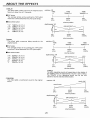
ABOUT ttHE EFFE⊂ TS
① DELAY
丁his effect adds a de!ay sound to the o百
ginal sound.
rateAime VR
TIME
Maximum delay ttme is 2.7seconds.
丁:ME
丁EMPO Xl
TIME
丁EMPO
X4
■丁AP button
丁he average tempo set by pushing the TAP button
min
more than 2 tirnes becomes the LFO cycie tempo.
center
(0%)
(50%)
■ Beat select button
volume pOsition
depth/sweep VR
・1/4" 丁EMPO=(A)× 1/4
DRY
TEMPO=(A)× 1/2
"3た "TEMPO=(A)× 3/4
"1" TEMPO=(A)× 1
"2" TEMPO=(A)× 2
DRY:EFFEC丁 =1:1
"1/2・
center
max
(50%)
(100%)
volume pOsition
②ECHO
丁his effect adds numerous de!ay sounds to the
origina!sound.
rateAime VR
TIME
TIME
TEMPO Xl
T:M匡
TEMPO X4
■丁AP button
The average tempo set by pushing the ttAP button
more than 2 times becomes the LFO cycle tempo.
min
center
(0%)
■ Beat select button
(50%)
volume position
depth/sweep VR
"1/4" 丁EMPO=(A)× 14
"1/2" 丁EMPO=(A)× 1/2
DRY
DRY:EFFEC丁 =1:1
"3/4"丁 EMPO=(A)× 3/4
"1"
"2"
丁EMPO=(A)× 1
丁EMPO=(A)× 2
_
m mw
n
・
i%
center
max
(50%)
(100%)
vo!ume position
XHOLD
③ REVERB
This effect adds a reverbё rant sound to the orig:nai
sound.
The echo repeating sound will repeat play in the rhythm of
the TEMPO when the depth/sweep volume is set io HOLD.
The TEMPO of the repeating sound can be set with
rate/time volume and beat select button.
rate/time VR
reverb hall
m!n
(0%)
center
(50%)
volume position
depth/sweё p
VR
DRY
DRY:EFFECT=1:1
center
(50%)
volume position
=20‐
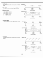
④ FLANGER
This effect adds a tirne‐ shifted sound to the originai
rate/time VR
丁IME
丁lME
sound.
TEMPO×
1
TIME
TEMPO× 4
■ TAP button
The average tempo set by pushing the ttAP button
more than 2 times becomesthe LFC)cycle tempo.
■ Beat select button
"1/4・
TEMPO=(A)×
"1/2" TEMPO=(A)×
"3/4" TEMPO=(A)×
TEMPO=(A)×
丁EMPO=(A)×
center
(0%)
(50%)
volume pOsition
depth/sweep VR
DRY
DRY:EFFEC丁 =1:1
1/4
1/2
3/4
1
n
i
m畔
"1"
・2"
min
2
center
max
(50%)
(100%)
volume position
※ Restarting the LFO
This feature restarts the LFO cycle tO gain the same
LFO effect when adiuSlng the depth/sweep v01ume and
beat select button.
⑤ RING MOD.
丁his effect modulates the original sound with sign
wave patterns.
rateitime VR
mod.freq.
LOW
mod.freq.
MiD
m:n
center
(0%)
(50%)
mod.freq.
HI
volume position
depth/sweep VR
DRY
DRY:EFFEC丁 =1:1
center
(50%)
volume pOsition
⑥ PITCH
SHiFTER
This effect changes the pitch Ofthe originai sound.
rate/time VR
SLOW
m:n
(0%)
center
max
(50%)
(100%)
vo!ume pOsition
depth/sweep VR
DRY
DNIEFFEC丁 =1:1
center
(50%)
voiume pOsition
-21-
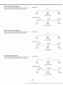
⑦ AUTO PAN
This effect changes the volume balance of lett and
rate/time VR
丁:ME
right.
■丁AP button
丁he average tempo set by pushing the TAP button
more than 2 times becomes the LFC)cycle tempo.
1日
1/4
"1/2" 丁EMPO=(A)× 1/2
"3/4" 丁EMPO=(A)× 3/4
"1"
"2"
TIME
TEMPO× 4
m:n
center
max
(0%)
(50%)
(100%)
Beat select button
"1/4" TEMPO=(A)×
TIME
TEMPO Xl
volume position
depth/sweep VR
DRY
DRY:EFFEC丁 =tl
丁EMPO=(A)× 1
TEMPO=(A)× 2
m:n
center
max
(0%)
(50%)
(100%)
volume position
③ VOCAL
CANCEL
This effect affects the mid frequency and cuts out
the vocal sound.
rate/time VR
cut
cut
M:D― LOW
m:n
(0%)
MiD― H!
center
max
(50%)
(100%)
vo!ume position
depth/sweep VR
DRY
min
(0%)
DRY:EFFEC丁 =1:1
center
max
(50%)
(100%)
volume position
③ VOCODER
This effect changes the originai sound to a robotic
rate/tirne VR
sound.
m:n
(0%)
center
max
(50%)
(100%)
volume position
depth/sweep VR
DRY
min
(0%)
DRY:EFFECT=1:1
center
max
(50%)
(100%)
volume position
‐
22‐
@Low PASS
FTLTER (MANUAL)
The Q changes with the rate/time volume. The
rate/time VR
Q→
←
depth/sweep volume adjusts the filter frequency.
■1:n
center
max
(0%)
(50%)
(100%)
volume position
depth/sweep VR
W
min
(0%)
center
max
(50%)
(100%)
volume pOsition
@eAl.ro PAss FTLTER (MANUAL)
The Q changes with the rate/time volume- The
rate/lme VR
depth/sweep volume adjusts the filter frequency.
Q→
←
min
center
max
(0%)
(50%)
(100%)
volume position
depth/sweep VR
ド千
:菫 上 ―一一一一 三
11笙
L一 ―一―一一 三 :│'W
m:n
center
max
(0%)
(50%)
(100%)
volume position
⑫ HIPASS F:LTER(MANUAL)
丁he Q changes wth the rate/time volume. 丁he
depth/sweep v91ume adiuStS the filterfrequency_
rate/time VFI
←
min
(0%)
Q→
center
(50%)
volume pOsition
depth/sweep VR
min
(0%)
H
ラ
center
(50%)
volume position
-23-
max
(100%)
⑬ LOW PASS FlLTER with LFO
⑭ BAND PASS F:LTER with LFO
⑮ HIPASS F:LIER with LFO
丁he filters frequency changes in the tirne cycle set
wnh the rate/time volume and TAP button.
rate/time vR
■ TAP button
丁he average tempo set by pushing the TAP button
oenter
max
(0%)
(50%)
(100%)
depth/sweep
m mw
1/2
3/4
1
m%
・ 2"
LFO
LFO
center
max
(50%)
(100%)
TEMPO=(A)× 1/4
"1/2" TEMPO=(A)×
"3/4" TEMPO=(A)×
"1" 丁EMPO=(A)×
4
volume position
│IBeat select button
14"
“
丁lME
TEMPO×
min
0
R F
V L
more than 2 times becomes the LFO cycle tempo.
TIME
TEMPO Xl
TIME
TEMPO=(A)× 2
闘e
ゾ
vo!ume position
※ Restarting the LFO
呪諮昴皇:咄 l精 齋圏
」議棚 .attuttnjh私 き
⑮ PHASER
丁his effect adds different phases to the original
rate/time VR
丁lME
T!ME
Xl
丁EMPO
sound.
TIME
TEMPO× 4
■丁AP button
The average tempo set by pushing the ttAP button
more than 2 tirnes becomes the LFC)cycle tempo.
center
(50%)
volume position
│IBeat select button
"1/4" TEMPO=(A)×
"1/2" TEMPO=(A)×
"3/4" TEMPO=(A)×
"1" TttMPO=(A)×
"2"
LFO
aり itude
1/4
1/2
3/4
│
1
min
TEMPO=(A)× 2
center
(0%)
(50%)
volume position
max
(100%)
※ Restarting the LFO
:馳l配思.利
-24‐
ud品
誌鷺諮島塁
よ
:咄 :精 稲 [鼠
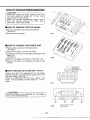
CAUT:ON
'When you change the fader, make it sure that
the main switch is turned off. lf not, may
cause noise or short circuit.
.When you use the screwdriver, make it sure
that you should choose the right side.
Othenruise, may break screws.
■ HOW
TO REMOVETHETOP PANEL.
① Remove a‖ fader knobs and the 4screws.
(See ig.A)
② Remove the top panei.
■
HOW TO CHANGE THE FADER UNIT
① Remove the screws on the fader panel.
(See ig.B)
② Remove the fader unttfrom the mixer.
③ Carefully remove the muki― cable connector from
fader unit.
(See ig.C)
④ Atach muni― cable connectorto new fader unl.
⑤ Poslion the fader unn carefully and secure wtth
screws.
Remove the
Юm
l颯
:nttl
鼈雷:h:昇 :d酔 鳥 ∬5ヽ 品片
∫電
牌 _Pcv u耐 。When“ C「
朧肌 晋ⅧЪ
unl t h鎖 Jbd,sd he swnchピ Pcv"
鷺譜
if猟
figoC
CAUT:ON
朧毬r螺 鶴R贅 胤niThCed,
Remove four scews.
│││││││││
do not loosen
fig.D
‐
25-
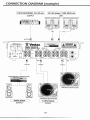
():CF‐ RUS or CF‐ R
◎ :CF‐ PCV
CONNECT10N DIAGMM Iexamplel
TAPE RECORDER,CD′ MD etc
OUTPUT
CD′ MD player′
TAPE DECK etc
LiNE
CDPLAYER IexVESTAX CDX‐ 16]
CDPLAYER[exVESTAX CDX‐
16]
TAPE RECORDER,CD,MD,DAT,etc.
00
ΨIユ紳
MASTER II
Vvestax
③
POWER AMPttF:ER[餞
TURNTABLE〔 ex.VESTAX PDX‐ 3000]
TURNTA3ι [relcvESTAX PDX‐ 3000]
AMPLIFIER
OUTPUT
TURNTABLE
PHONO
‐
26-
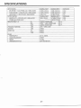
SPECIFICAT10NS
:NPUT SEC■ ON
NOMiNALiNPtrr
MAXIMUM INPUT
:MPEDANCE
MIC IN:PGM‐ 1∼ 2(16.3 PHONE」 ACK/UNBULANCED)
‐
52dBv(2.5Vrrns)
‐
30dBv(32mVrrns)
3.3kΩ
PHONO IN:PGM‐ 1∼ 4(RCA PIN」 ACK/UNBULANCED)
‐
45dBv(5.6VrFnS)
‐
22dBv(80mVmls)
49kΩ
‐
4dBv(1.OV)
+1ldBv(70Vrns)
7kQ
LINE IN:PGM-1∼ 4(RCA PIN」
ACK/UNBULANCED)
OUTPUT SECT10N
MASTER OUT■ ∼2(RCA P:N」ACKノ UNBULANCED)
NOMiNAL INPtrr
MAXlMUM INPU r
IMPEDANCE
OdBv(1.OVrrns)
+17.5dBv(7.5VFnS)
2200
1∞ mW(470102d)
PHONES(16.3 PHONE」 ACK)
:SOLATER(PGM-1∼
4)
:Hl
:MlD
2.5kHz≦
≦250Hz′ B00ST:16dB
CUT:― ∞
S/N RAT:0
:LiNE
70dB≦
CROSS TALK
:C.F.
65dB≦
WttGHT
D:MENS10NS(W× H× D)
∞
CUT:‐
FREQUENCY RESPONSE
:PGM
CUT:‐
250Hz-2.5kHz/800ST:+6dB
:LOW
:日 NE
OTHER
POWER SUPPLY
POWER REQUiREMENT
/B00ST:16dB
>8Ω
∞
20Hz∼ 20KHz± 3dB
65dB≦
AC‐ 14,1500mA
≒20VA
≒4.5kg
264× 105× 260(mm)
-27-
Vestax Corporation
AUG 2007 VMC-004FXu①
P/N:4301‐ 7316● 0
VVestax
mixing controller
嘔ヽ C‐ 002X■ u rCJB
嘔ヽ CE004XLu rCJB
ヽ C‐ 004FXu石 UB
こ
Supplemental Instruction Sheet
Vestax Corpotation
1-186 Wakabayashi, Setagaya-ku, Tokyo 154{023 Japan
Phone 03-341 2.701
I
Fax 03.341 2.701 3
Web : www.vestalcom
Vestax Europe Technical Support
Rheinstr.2l3 D-53332 Bornhelm Germany
P hone 49(0)2222-95-23-7 2 F ax 49(012222-95-23-7 4
Please be sure to completely read this supplementalinstruction sheet along with the useris
manual ofthe following products.(PrOducts iabeled"TUB")
●
●
●
O
VMC-002XLu TUB
VMC-004XLu TUB
VMC-004FXu TUB
HOWTO USE USB
Connect the mixers USB inpuVoutput port to a computers USB port with a USB cable.
Sound InpuVOutput will be enabled simply by connecting via USB, using the OS internal driver.
XUSB board features
. USB1.1(US82.0 compatible) compliant
. USB BUS power operated
The USB POWER LED will light up after the mixer is identified by the computer and the power
has been supplied.
◇
USB PORT CHANNEL ASSIGN
(1)VMC-002XLu ttUB
⇒ Please referto(27),page 13 ofthe VMC‐ 002XLu users manual.
Assigned to:
lNPUT:LINE2/USB ofPGM2
0UTPUT:MASttER OUTPU丁
(2)VMC¨ 004XLu_TUB
⇒ Please refer to(20),page 13 ofthe VMC-004XLu users manual.
Assigned toi
:NPUT:LINE4/USB ofPGM4
0UTPUT:MASTER OUTPU丁
(3)VMC-004FXu_TUB
⇒ Please refer to(29),page 18 ofthe VMC‐ 004FXu users manual.
Assigned to:
INPU丁 :LINE5/USB ofPGM3
0UTPU丁:MASTER OUTP∪ T
υSBノ ArPυ T/oυ TPυ T
PORT
SYSTEM REQUIREMENttS
◇
Minimum System requirement
OOS(Operating System )
Windows:
Windows9S/98SE/Me, 2000/XP
(Windows XP will require the latest USB audio driver available from Windows update website)
Macintosh:
. Mac OS X 9.1 and later versions
. Mac OS X 10.0 English Edition and later versions
. Mac OS X 10.1 Japanese Edition and later versions
(Mac OS X 10,0 Japanese Edition is NOT SUPPORTED)
Allversions before OS X 9.1 is NOT SUPPORTED
X
'
NOTE
The minimum system requirements above are for the mixer. If the minimum system requirement
of the software is higher than the mixers requirement, please prepare an advanced operating
system qualified.
Macintosh CPU accelerator cards are not supported. The computer must have USB connection.
. YAMAHA AC-XG Audio Device does not work with this mixer.
'
*Above are minimum requirements
and does not guarantee performance for all computers and
devices.
O
USB connection confirmation
The USB POWER LED (red) will light up when the mixer is connected to a computer via USB and
indicate that USB inpuVoutput is operating.
Please follow the instructions below to confirm if the computer has identified the mixer via USB
connection.
Windows XP:
To check connection status in Windows XP, view [control panel] > [system] > [hardware] > [device
managerl > inside [sound, video and game controller]find [USB Audio device] .
lf both are displayed and the status is "This device is installed correctly", the mixer and computer
is connected correctly.
Macintosh:
To check the connection status in Macintosh, view [Applications] > [Utilities] > [Audio MlDl setting] >
[MlDl device] and find "Vestax PC-CONTROLER'. The property shall show,
* Device:Vestax PC CONTROLLER
* Manufacturer: Vestax
* Model: Vestax PC-CONTROLLER
The computer and the mixer are connected correctly if the information above is shown.
AUG 2007_VMC■ UB EO
P′ N:4301‐ 7320■
0