1
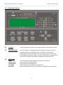
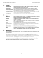
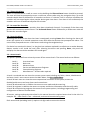
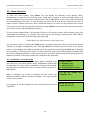
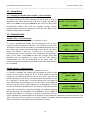
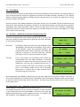
ZERIO PLUS
EDA-Z5008, Z5020 & Z5100
USER MANUAL
ZPControlUserMan_r100
Revision 1.00
EDA-Z5008, Z5020 & Z5100 – User Manual
ZPControlUserMan_r100
_____________________________________________________________________________________________________
0359
Electro Detectors Limited
Electro House
Edinburgh Way
Harlow, Essex
CM20 2EG, UK
14
0359 CPR 00226
DOP_EDA_Z5100 (covers all models)
EN54-2:1997+A1:2006
EN54-4:1997+A1:2002+A2:2006
EN54-25:2008
Control and indicating equipment for fire detection and fire alarm systems for buildings
Models: EDA-Z5008, EDA-Z5020, EDA-Z5100
Optional functions with requirements:
7.8
Output to fire alarm devices
7.9.1 Output to fire alarm routing equipment
7.11 Delays to outputs
7.12 Dependency on more than one alarm signal - Type C dependency
7.13 Alarm counter
8.3
Fault signals from points
9.5
Disablement of addressable points
10.0 Test condition
2
EDA-Z5008, Z5020 & Z5100 –User Manual
ZPControlUserMan_r100
_____________________________________________________________________________________________________
Revision History
V1.00
19/01/2015
User manual first release.
3
EDA-Z5008, Z5020 & Z5100 – User Manual
ZPControlUserMan_r100
_____________________________________________________________________________________________________
Introduction
Electro Detectors has been manufacturing radio fire alarm systems since 1987 and with the
introduction of a harmonised specification for Europe has complemented its range of products to meet
EN54 Part 25. Based on the popular Zerio system, the updated Zerio Plus has been designed to be
capable of handling 240 devices in 100 zones. Typical installations would include small offices, private
houses, HMO’s, guesthouses and small hotels.
This manual contains information to enable a user to operate the Zerio Plus control panel and the
range of Zerio Plus devices. This product should be installed, commissioned and maintained by
qualified service personnel in accordance with codes of practice, statutory requirements and IEE
regulations for electrical equipment in buildings.
4
EDA-Z5008, Z5020 & Z5100 –User Manual
ZPControlUserMan_r100
_____________________________________________________________________________________________________
Contents
1.0
2.0
3.0
4.0
5.0
6.0
7.0
8.0
Front Panel Layout
User Operation
2.1
System Normal
2.2
Fault Conditions
2.3
Silence Buzzer
2.4
Reset a Fault
2.5
Alarm Conditions
2.6
Silence the Alarm
2.7
Re-sound the Sounders
2.8
Reset the Alarm
2.9
Access Levels
Menu Operation
3.1
Quick Menu
Setup Menu
4.1
Time and Date
Disable/Enable Menu
Test Mode
6.1
Test Zone
6.2
Clear Zone In Test
6.3
Lamp and Buzzer Test
Faults
Maintenance
5
EDA-Z5008, Z5020 & Z5100 – User Manual
ZPControlUserMan_r100
_____________________________________________________________________________________________________
1.0 - Front Panel Layout
①
②
③
⑤
④
⑥
①
Fire LEDs
If the panel goes into alarm, these LEDs will flash until the panel is reset.
②
Zone Alarm LEDs
In a fire condition, the appropriate zone LED will illuminate. If the fire
condition exists across multiple zones, multiple zone LEDs will be
illuminated. The zone LEDs will remain lit until the panel is reset. *The
EDA-Z5008 8 Zone panel is shown. The EDA-Z5020 panel is equipped with
20 zone LEDs and the EDA-Z5100 is equipped with 100 zone LEDs.
③
Status LEDs
Supply
Delays Active
Disablements
Test Mode
More Info
This LED will be illuminated when mains power is present.
Illuminated if delays are enabled.
Illuminated for any disablement.
Illuminated if any test modes are operational.
More information on the system condition is available in the event log.
6
EDA-Z5008, Z5020 & Z5100 –User Manual
ZPControlUserMan_r100
_____________________________________________________________________________________________________
④
Fault LEDs
Common Fault
Device or panel has a fault. See main display for details. This LED will
remain lit until the panel has been reset.
System Fault
Fault that affects system performance. See main display for details.
Sounder Flt/Disable If the LED is flashing, there is a fault with one or more sounders. If the
LED is solid, the one or more sounders have been disabled.
Routing Flt/Disable If the LED is flashing, there is a fault with the fire routing relay. If the LED
is solid, the fire routing relay has been disabled.
Routing Active
Illuminated when the fire routing relay has been activated.
⑤
Keys
Menu/Info
Function
Cancel
Enter
Re-sound Alarm
Silence Alarm
Silence Buzzer
Reset
⑥
Press to initiate the menu system. If held down for longer than 2 seconds,
the LEDs will follow a test sequence (lamp test).
This button is disabled by default, though it can be programmed to do a
number of functions.
Used to return to the main screen from a menu or to return to the menu
from a programming screen.
This is used to accept information programmed into the panel.
Following an alarm condition that has been silenced but not reset, this
button will re-sound the alarm.
If the panel is in a fire condition this will silence the sounders.
Silences the panel buzzer for all currently displayed faults or alarms.
Resets the panel from an alarm or fault condition. Note that the system
must be silenced before it can be reset from a fire condition.
Navigation Keys
The navigation keys are numbered 1 to 4. This is to allow the user to enter a 4 digit access code
when prompted.
Use the keys to navigate through the menu structure and programming/status screens. In a
multiple fault or alarm condition, the up and down arrow keys allow the user to scroll through
all the current events. The display will also scroll automatically every 4 seconds.
In the panel menus, use ↑ and ↓ to scroll through the available menu options. Press → to
select the currently highlighted menu. Press ← to go back to the previous menu.
7
EDA-Z5008, Z5020 & Z5100 – User Manual
ZPControlUserMan_r100
_____________________________________________________________________________________________________
2.0 - User Operation
2.1 - System Normal
In normal operation the screen will show either the date and time,
or the supplier/service contact details. The unit can also be
configured to alternate between the two. If configured this way, the
display will change every 4 seconds. Also a single green ‘Supply’ LED
will be illuminated.
Tuesday
01-01-2013
12:04:36
2.2 - Fault Conditions
If a fault occurs, the internal buzzer will sound and a message will
001 Zn:001 VFY FAULT
be displayed. The first line details the current fault number, the
SMOKE DET 001
zone and the type of fault. The second line details the device type
Entrance Hall
and the device number. The third and fourth lines display the device
location text (if programmed). The description has a maximum
length of 40 characters across 2 lines. Appropriate action should be
taken to remedy the fault as this may affect the operation of the fire alarm system. If in doubt, the
system maintenance company should be contacted. If more than one fault exists on the system they
will scroll round every 5 seconds. Pressing the ↑ or ↓ cursor key will display the next or previous fault.
2.3 - Silence Buzzer
If the panel buzzer is sounding following a fault or alarm, it can be silenced with the Silence Buzzer key.
Once the Silence Buzzer button has been pressed the panel assumes that the fault has been
acknowledged and does not re-sound the buzzer, unless a new fault occurs. The LED on the device will
continue to flash until the fault is reset – see below.
2.4 - Reset a Fault
A fault will be displayed on the panel until the system is reset, even
Enter Access Code
if the fault condition has been rectified. Assuming the fault has
been rectified; pressing Reset on the panel and entering an access
---code using the navigation keys will reset the panel and the devices
on which the fault has occurred. The system normal screen will then
be displayed. If the fault is still present or re-occurs, it will be re-displayed. Where there are multiple
faults, all will be reset at the same time. It is not necessary to silence a fault before resetting it. The
particular device or devices in fault will also flash a green LED and beep.
2.5 - Alarm Conditions
In a fire condition, a screen similar to this will be displayed. The fire
001 Zone 001
LEDs will flash and the zones in alarm LED(s) will be illuminated.
SMOKE DET 001
Assuming the system is programmed to do so, the system sounders
Conference Room
will be activated and the routing active LED will illuminate. The first
line of the display shows the event number and the zone number.
The second line details the device type and its number. If the device location has been programmed
into the panel, it will be displayed on the third and fourth lines. Scroll through multiple alarms using
the ↑ and ↓ keys.
8
EDA-Z5008, Z5020 & Z5100 –User Manual
ZPControlUserMan_r100
_____________________________________________________________________________________________________
2.6 - Silence the Alarm
When it is certain that it is safe to return to the building the Silence Alarm button should be pressed.
The user will then be prompted to enter a valid user access code using the navigation keys. Up to 30
seconds should then be allowed for all sounders to silence. If a device is still in an alarm condition the
sounders will not sound again unless another device goes into alarm. If an alarm is left unsilenced, the
sounders will turn off automatically after 30 minutes.
2.7 - Re-sound the Sounders
There may be times when the sounders have been mistakenly silenced – for example if the alarm was
genuine but someone pressed silence. The Re-Sound Alarm button followed by a valid access code will
activate the sounders again.
2.8 - Reset the Alarm
Assuming the cause of the alarm has been investigated; pressing Reset after silencing the alarm will
return the system to its normal operation screen and reset the devices that prompted the alarm. The
user will be prompted to enter a valid access code using the navigation keys.
If a device has remained in alarm (i.e. the glass has not been replaced in a callpoint or a smoke detector
detects smoke is still inside the unit) after silencing the alarm and pressing Reset, the panel will
redisplay the alarm and the sounders will sound again.
2.9 - Access Levels
The panel is protected from misuse by means of four access levels. The access levels are as follows:
Level 1
Level 2A
Level 2B
Level 3A
Level 3B
Level 4
Untrained user
Basic user
Advanced user
Service and Maintenance Engineer
Commissioning Engineer
Manufacturer – Access tools required
Enter Access Code
----
A Level 1 untrained user can view the current system state including any faults, alarms, disablements
and tests. Level 1 users cannot access the Main Menu. See 3.1 – Quick Menu.
A Level 2A basic user can view the current operational condition of the system, access the
disable/enable menu and may silence and reset alarms.
A Level 2B advanced user in addition has access to test mode and the event log.
A Level 3A engineer in addition has access to system and device information and the verify table.
A Level 3B commissioning engineer has access to all system options, including programming and
configuration of devices and hardware.
All menus, settings and options described in this manual show the required access level in the title. For
example: 6.2 – Clear Zone in Test – advanced, service and commissioning users
Each access level (excluding level 1) requires a 4 digit code to access the menus.
9
EDA-Z5008, Z5020 & Z5100 – User Manual
ZPControlUserMan_r100
_____________________________________________________________________________________________________
3.0 - Menu Operation
To enter the menu system, press Menu. This will display an overview of any alarms, faults,
disablements or tests that are currently active, along with an option to access the Main Menu. The
options available on the main menu and sub-menus will be dependent on the access code entered and
its corresponding access level. To scroll through the menu the ↑ and ↓ keys should be pressed. In
order to select a menu option the → key should be pressed. To return to the previous menu screen
from a sub-menu the ← key should be pressed. Pressing Cancel will return to the system screen where
any faults or alarms will be displayed if present.
For every menu option listed in this manual, its place in the menu structure will be shown in grey text
underneath the heading. For example, the event log can be found by selecting the ‘Main Menu’,
followed by ‘View Events’ and selecting ‘View Event Log’.
1.Main Menu>>4.View Events>>2.View Event Log
If a non-menu screen is selected the Cancel button should be pressed to return to the menu without
making any changes. Subsequently, then pressing Cancel for a second time will return to the system
screen. If any changes are made to settings, these are generally saved using the Enter key as detailed
on the display. If an alarm occurs while in menu mode, the menu will be automatically cancelled, and
the alarm message displayed. If a fault occurs while in the menu mode, the fault LED will light but the
display will remain in the menu mode until cancelled in the usual way.
3.1 - Quick Menu – all access levels
Pressing Menu once will display the Quick Menu. Navigate using
the cursor keys. Any active alarms, faults, disablements or tests will
be displayed. No access code is needed to view the events listed.
You will only be prompted to enter an access code if you select ‘1Main Menu’.
When a category (e.g. Faults) is selected, the first screen will
display information such as the device number, zone, type of fault
and any text location.
Pressing the → key will display the time and date that the event
happened.
10
1>Main Menu
2 Alarms(000)
3 Faults(002)
4 Disablements(000)
001 Zn:001 SHORT CCT
CONTROL IP1
Time:12:00:08
Date:25/06/13
EDA-Z5008, Z5020 & Z5100 –User Manual
ZPControlUserMan_r100
_____________________________________________________________________________________________________
4.0 - Setup Menu
4.1 - Changing the system Time and Date – all access levels
1.Main Menu>>1.Setup>>1.Time & Date
To change the time and date settings use the ← and → keys to
navigate to the value, and the ↑ or ↓ keys to select the desired
value. Press Enter to accept or Cancel to exit. The Zerio Plus panel
automatically adjusts the clock for daylight savings. Should
complete power be lost the panel will revert the time back to the
default of 01/01/2013 12:00:00
Time: 12:39:00
Date: 01-01-2013
ENTER to save
5.0 - Disable/Enable
Disable a Zone – all access levels
1.Main Menu>>2.Disable/Enable>>1.Disable>>1.Zone
If a zone is disabled the system will not display any fire or fault
events for devices located in that zone. This includes any call point
activations. Select the zone number to be disabled and press the →
key. Select the timeout period followed by the → key. All access
levels can disable a zone for a period of 1 to 96 hours. A
commissioning user can disable a zone indefinitely by selecting a
time of ‘00’ hours. Press Enter to save the change. ‘Zone XXX
disabled’ will be displayed on screen and the LED marked
‘Disablements’ will now be illuminated on the panel. After the
timeout period has elapsed, the isolated zone(s) will automatically
be re-enabled.
Select Zone 001↕
Use ← → keys
Press ENTER to
Disable Zone 001
Disable a Device – all access levels
1.Main Menu>>2.Disable/Enable>>1.Disable>>2.Device
If a device is disabled the system will not display any fire or fault
Select Device 001↕
events for that device. Using the ↑ or ↓ keys select the device
SMOKE DET
number to be disabled and press the → key. Select the timeout
period followed by the → key. All access levels can disable a zone
Use ← → keys
for a period of 1 to 96 hours. A commissioning user can disable a
zone indefinitely by selecting a time of ‘00’ hours. Press Enter to
save the change. ‘Device XXX disabled’ will be displayed on screen
Press ENTER to
and the LED marked ‘Disablements’ will now be illuminated on the
Disable
Device 001
panel. After the timeout period has elapsed, the isolated device(s)
will automatically be re-enabled. Press Cancel to exit or Enter to
disable more devices. If all devices in a zone are disabled, the zone
is also disabled. If a sounder detector is disabled, only the detector component ceases to function. The
device will still sound in an alarm. If a square sounder is disabled, only the reporting of faults from the
device is disabled – the sounder will still sound in an alarm.
11
EDA-Z5008, Z5020 & Z5100 – User Manual
ZPControlUserMan_r100
_____________________________________________________________________________________________________
Disable Panel Inputs – all access levels
1.Main Menu>>2.Disable/Enable>>1.Disable>>3.Panel Input
The two monitored inputs can each be disabled for a period of time specified by the user, dependent
on their access level. All access levels can disable an input for a period of 1 to 96 hours. A
commissioning user can disable an input indefinitely by selecting a time of ‘00’ hours. Press Enter to
save the change ‘Input XXX disabled’ will be displayed on screen and the LED marked ‘Disablements’
will now be illuminated on the panel. The system will ignore any fire or fault event from that input
within that time. After the timeout period has elapsed any disabled inputs will automatically be
enabled again.
Disable Sounders – all access levels
1.Main Menu>>2.Disable/Enable>>1.Disable>>4.Sounders
The sounders can be disabled for a period of time specified by the user, dependent on their access
level. All access levels can disable a sounder for a period of 1 to 96 hours. A commissioning user can
disable a sounder indefinitely by selecting a time of ‘00’ hours. The sounders will ignore any fire event
from the panel within that time. Both the ‘Disablements’ LED and the ‘Sounder Flt/Disable’ LED will be
illuminated. After the timeout period has elapsed any disabled sounders will automatically be enabled
again. When sounders are disabled, any hard wired sounder circuits will not display short circuit and
open circuit faults.
Disable Fire Routing – all access levels
1.Main Menu>>2.Disable/Enable>>1.Disable>>5.Fire Routing
The fire routing relay can be disabled for a period of time specified by the user, dependent on their
access level. All access levels can disable the relay for a period of 1 to 96 hours. A commissioning user
can disable the relay indefinitely by selecting a time of ‘00’ hours. The relay will ignore any fire event
from the system within that time. The ‘Disablements’ LED and the ‘Routing Flt/Disable’ LED will be
illuminated. After the timeout period has elapsed, the relay (if still disabled) will automatically be
enabled again. When Fire Routing is disabled, open circuit and short circuit faults will not be reported.
Disable Fault Relay – all access levels
1.Main Menu>>2.Disable/Enable>>1.Disable>>6.Fault Relay
The fault relay can be disabled for a period of time specified by the user, dependent on their access
level. All access levels can disable the relay for a period of 1 to 96 hours. A commissioning user can
disable the relay indefinitely by selecting a time of ‘00’ hours. The relay will ignore any fault event from
the system within that time. After the timeout period has elapsed, the relay (if still disabled) will
automatically be enabled again. To comply with EN54, the fault relay should not be disabled.
12
EDA-Z5008, Z5020 & Z5100 –User Manual
ZPControlUserMan_r100
_____________________________________________________________________________________________________
Enable a Zone – all access levels
1.Main Menu>>2.Disable/Enable>>2.Enable>>1.Zone
To enable a previously disabled zone, select it using the ↑ or ↓ keys and press Enter. To enable more
zones press Enter, or Cancel to exit. If all zones have been enabled ‘No Zones to enable’ will be
displayed. If a disabled zone is enabled; and no other isolated devices/zones remain, then the
‘Disablements’ LED will extinguish.
Enable a Device – all access levels
1.Main Menu>>2.Disable/Enable>>2.Enable>>2.Device
This menu allows the user to enable a previously disabled device.
Using the ↑ or ↓ keys select the device number to be enabled and
press Enter. To enable more devices, press Enter, or Cancel to exit.
If all devices have been enabled ‘No Devices to enable’ will be
displayed. If a previously disabled device is enabled; and no other
isolated devices/zones remain, then the ‘Disablements’ LED will
extinguish.
Select Device 001↕
SMOKE DET
Use ← → keys
Press ENTER to
Disable Device 001
Enable Panel Input – all access levels
1.Main Menu>>2.Disable/Enable>>2.Enable>>3.Panel Input
Select this option to enable an input that has previously been disabled. Choose the input from the list
and press Enter to confirm.
Enable Sounders – all access levels
1.Main Menu>>2.Disable/Enable>>2.Enable>>4.Sounders
Select this option to enable sounders if they have been previously disabled.
Enable Fire Routing – all access levels
1.Main Menu>>2.Disable/Enable>>2.Enable>>5.Fire Routing
Select this option to enable the fire routing relay, if it has been previously disabled.
Enable Fault Relay – all access levels
1.Main Menu>>2.Disable/Enable>>2.Enable>>6.Fault Relay
Select this option to enable the fault relay if it has been previously disabled. To comply with EN54, the
fault relay should not be disabled.
13
EDA-Z5008, Z5020 & Z5100 – User Manual
ZPControlUserMan_r100
_____________________________________________________________________________________________________
6.0 - Test Mode
Test mode allows a system to be tested with minimal disruption to the occupants of a building. When a
zone is placed into test mode the engineer can choose to disable sounders, actuators or any output
devices. Should anything happen outside of these selected zones the system will operate as normal
and the sounders will sound.
Once the various Test Mode parameters have been chosen, the Test Mode LED will illuminate on the
main panel. Once selected, the option is also given to save the parameters so that they can be used for
subsequent test mode operations. When a zone has been put into the Test condition, subsequent
alarms from devices in that zone do not appear on the Main Screen as an alarm, but appear as a “FIRE
TEST” event in the event log.
6.1 - Test Zone – advanced, service and commissioning users
1.Main Menu>>3.Test Mode>>1.Test Zone
Scroll to the appropriate zone number using the ↑ or ↓ keys, and
press the → key to select that zone. Follow the on screen prompts
to set the test parameters.
Zone 001↕
Use ← → keys
Sounders:
Timeout:
If sounders within the zone are to be disabled, select
‘NO SOUND’. Alternatively the sounders can be set to
‘6 SEC SOUND’, where any activated sounders will
automatically silence after 6 seconds. This allows the
engineer to perform a one-man walk test, without
the need to return to panel to silence the alarm.
This is the amount of time before the system will
automatically exit test mode operation. A timeout
period of ‘0’ means that the zone will remain in test
indefinitely, until the test is disabled by the user. In
order to operate this panel and comply with EN54
part 2, this setting should not be set to anything
other than ‘0’. It can be set in 1 hour intervals and is
selected using the cursor keys.
Select Tone
NO SOUND↕
Use ← → keys
Timeout (hrs) 001↕
Use ← → keys
Zone 001
in Test
ENTER to continue
Once completed, press Enter to place the zone into test mode with the chosen settings. ‘Zone XXX in
Test’ will be displayed on screen and the ‘Test Mode’ LED will illuminate. Multiple zones can be tested
at the same time, by selecting ‘Enter more Zones’. The zone tests will be visible in the ‘5-Tests’ section
of the quick menu.
6.2 - Clear Zone in Test – advanced, service and commissioning users
1.Main Menu>>3.Test Mode>>2.Clear Zone in Test
This option allows the user to cancel test mode for a zone currently
in test. Select the zone and press Enter. If no zones are in test the
display should show the screen opposite and the ‘Test Mode’ LED
will extinguish. Press Cancel to return to the menu.
14
No Zones in Test
CANCEL to exit
EDA-Z5008, Z5020 & Z5100 –User Manual
ZPControlUserMan_r100
_____________________________________________________________________________________________________
6.3 - Lamp/Buzzer Test – advanced, service and commissioning users
1.Main Menu>>3.Test Mode>>3.Lamp/Buzzer Test
This option will illuminate all the panels LEDs in sequence, to check they are working properly. The
panel buzzer will also sound. A quick lamp test can be performed from any screen by holding down the
Menu button for 2 seconds.
7.0 - Faults
The panel continuously monitors hardware, battery life and
002 Zn:001 REMOVAL
connections across the system. If a fault is found, it will be
SMOKE DET 001
displayed on the panel screen, the buzzer will sound and the
Kitchen
common fault LED will be illuminated. The first line of the display
shows the event number, followed by the zone number and the
type of fault. The second line details the type of device and the
device number. The third line displays any location text (if programmed).
If the panel displays any faults, contact your alarm maintenance or installation company for advice.
8.0 – Maintenance
The Zerio Plus system should be maintained in accordance with the regulations and codes appropriate
to the country of installation. Follow the test schedule recommended by your installer or maintenance
company. This schedule is based on BS5839 codes of practice.
Daily Actions
The user should check that the panel indicates normal operation. If any faults exist, they should be
recorded and the responsible person or maintenance company should be notified.
Weekly Actions
The user should put at least one callpoint or detector in to alarm, checking that the correct device/zone
is indicated on the panel and that the programmed sounders activate. A different device should be
tested this way each week. A lamps test should be carried out and any inactive LEDs reported (refer to
section 8.3).
Quarterly Actions
The maintenance engineer should test at least 25% of detectors and 100% of callpoints. The devices
tested should be varied so that each device will have been tested at some point in any given 12 month
period. The panel battery connections and any relay or input connections should be checked. A visual
inspection of the panel should be carried out. Check that there are no outstanding issues in the
logbook to be addressed. A lamps test should be carried out and any inactive LEDs reported.
Annual Actions
The maintenance engineer should carry out a complete walk test. The panel battery should be tested
(see information below) and replaced if necessary. A dump of the verify table and panel table should
be taken and analysed for any change to previous records. A visual inspection of the panel should be
carried out. A lamps test should be performed and any inactive LEDs reported.
15
Zerio Plus Hardware
Product
EDA-A6000
EDA-A6030
EDA-A6060
EDA-C5000
EDA-D5000
EDA-D6000
EDA-D6030
EDA-R5000
EDA-R6000
EDA-R6030
EDA-T5000
EDA-T5100
EDA-T6080
Description
Radio Sounder
Radio Sounder with LED Beacon
Radio LED Beacon
Radio Callpoint/Break Glass Unit
Radio Heat Detector
Radio Heat Detector with Combined Sounder
Radio Heat Sounder Detector with LED Beacon
Radio Optical Smoke Detector
Radio Optical Smoke Detector with Combined Sounder
Radio Optical Smoke Sounder Detector with LED Beacon
Radio Transmitter Unit
Radio Silence Alarm Button
Radio Input/Output Unit DC
EDA-Y5000
EDA-Z5008
EDA-Z5020
EDA-Z5100
EDA-Z6000
EDA-Z6001
EDA-Z6010
EDA-Z5008FS
EDA-Z5008SS
EDA-Z5008SZ
EDA-Z5000
Dipole Weatherproof Antenna
8 Zone Radio Control Panel
20 Zone Radio Control Panel
100 Zone Radio Control Panel
Radio Booster Panel with I/O
Radio Booster Panel
Wired Intelligent Antenna
8 Zone Flush Mounted Wired Remote Display (Stainless Steel)
8 Zone Surface Mounted Wired Remote Display (Stainless Steel)
8 Zone Standard Enclosure Wired Remote Display
Survey Kit
Battery Type
3 x EDA-Q690
3 x EDA-Q690
3 x EDA-Q690
1 x EDA-Q690
1 x EDA-Q690
2 x EDA-Q690
2 x EDA-Q690
1 x EDA-Q690
2 x EDA-Q690
2 x EDA-Q690
1 x EDA-Q690
1 x EDA-Q690
1 x EDA-Q690
Electro-Detectors Limited
Electro House,
Edinburgh Way,
Harlow,
Essex,
CM20 2EG
Email: [email protected]
Web: www.electrodetectors.co.uk