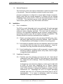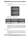
1
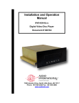
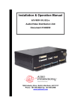
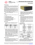
Product Installation
Manual
rL
Digital Video Disc Player
Model #’s: DVD-021-0x-x
Document #540125
7300 Industry Drive, North Little Rock, AR 72117
Phone: 501-955-2929 Fax: 501-955-2988
AUDIO INTERNATIONAL, INC.
11/98
Revision History
Rev. Level
IR
Date
11/98
Description
Initial Release
Applicable Documents
Document
#
N/A
560032
Drawing #
522187
N/A
Description
DVD-021-0x-x Outline Drawing
Operation Guide
2
Document #540125, Rev. IR, Model No.: DVD-021-0x-x
AUDIO INTERNATIONAL, INC.
11/98
Service Bulletin List
Service
Bulletin #
Subject
Manual
Revision #
Manual
Revision
Date
List of Illustrations
Section
No.
Description
3
Document #540125, Rev. IR, Model No.: DVD-021-0x-x
Page #
AUDIO INTERNATIONAL, INC.
11/98
Table of Contents
Section
Description
Page
1.0
1.1
1.2
1.3
1.4
General Information…………………………………………………..
Introduction……………………………………………………………...
Purpose of the Equipment…………………………………………….
Operational Features…………………………………………………..
Optional Equipment…………………………………………………….
5
5
5
5
6
2.0
2.1
2.2
2.3
2.4
2.5
2.6
2.7
2.8
2.9
Installation……………………………………………………………..
Prior to Installation……………………………………………………..
Unpacking & Inspection………………………………………………..
Cautions & Warnings…………………………………………………..
Wiring Requirements…………………………………………………..
Physical Requirements………………………………………………...
Electrical Requirements……………………………………………….
Pinouts / Descriptions………………………………………………….
Connector / Mating Connector Information………………………….
Post Installation Test…………………………………………………..
6
6
6
7
7
8
8
9
9
9
3.0
Operation……………………………………………………………….
9
4.0
Troubleshooting………………………………………………………
10
5.0
5.1
5.2
Specifications and Drawings……………………………………….
Unit Specifications……………………………………………………...
Applicable Drawings……………………………………………………
10
10
11
PROPRIETARY NOTICE: Despite any copyright notice, this data and information disclosed herein is
unpublished and contains confidential, proprietary design owned by Audio International Incorporated.
Neither this data nor the data contained herein shall be reproduced, used or disclosed to anyone
without the written authorization of Audio International Incorporated.
4
Document #540125, Rev. IR, Model No.: DVD-021-0x-x
AUDIO INTERNATIONAL, INC.
11/98
MODEL NO.
DVD-021-0x-x
Digital Video Disc Player
1.0
General Information
1.1
Introduction
This manual contains information for the installation of the Audio
International, Inc. (AI) Digital Video Disc Player, Model No. DVD-021-0x-x.
The “-0x” in the model number represents the specific model number (-01,
-02, 03). The “-x” suffix represents the type of connector utilized.
Information contained within this publication includes relative physical,
mechanical, and electrical characteristics. Also included within this
publication are additional references needed for installation of the unit.
1.2
Purpose of the Equipment
The DVD-021-0x-x is a high-quality video disc player specifically designed
to meet the special requirements of aircraft use. This video disc player
represents a new digital medium with the capacity to incorporate an entire
feature film - up to 133 minutes of brilliant, full-motion video per side on a
5” DVD compact disc. Also, the DVD unit plays standard 5” audio CD’s.
The DVD can be mounted in a cabinet or bulkhead. AI source equipment
can be optionally controlled by infrared remote. Playback options with the
remote control unit include visual search, pause, play, stop, fast forward
and rewind.
1.3
Operational Features
Operational features of the DVD-021-0x-x include hi-fidelity, digital stereo
audio output, video resolution of 720 pixels/horizontal line, operation
directly from 28 VDC, and infrared remote control capacity. These units
are fully compatible with AI’s proprietary RS-485 digital data bus control
systems.
The DVD format offers an array of interactive video features. Each disc
can provide up to eight soundtrack language options and up to 32
subtitles. Digital control enables frame by frame disc advancement, slowmotion video playback, instant jumps to any point in a movie, fastforwarding, or freezing on a single frame. Also, favorite order or random
segments can be programmed. All of the aforementioned interactive
video features are dependent upon manufacturer programming applied to
each DVD disc at the time of release.
5
Document #540125, Rev. IR, Model No.: DVD-021-0x-x
AUDIO INTERNATIONAL, INC.
1.4
11/98
Optional Equipment
The front bezel of the units can be customized to match the interior style
of any aircraft. They can be plated or painted to match any interior.
AI source equipment is configured to accept digital infrared commands.
Digital codes allow the source equipment to interface with an infrared
handheld remote control (AI-RC1-17xxxx) via an infrared receiver, IFR-9A
or IFR-485. This hand-held remote control operates functions such as
visual search, pause, play, stop, fast-forward, and rewind.
2.0
Installation
2.1
Prior to Installation
The DVD is a small, lightweight unit to use and install. All audio input and
output cables on the unit should use twisted shielded pair (22 AWG
minimum) unless otherwise specified. The units must be attached to
conform to the standards designated by the customer, installing agency,
and existing conditions as to the unit location and type of installation. The
following should be carefully considered before installation:
2.1.1 Select a mounting location for the unit where 28 VDC power, video,
and audio signal have been previously installed. Refer to Section
5.0 Specifications and Drawings for location of mounting points.
2.1.2 All headphone amplifiers and line level amplifiers should be located
no more than three feet away from source equipment. Long lowlevel audio runs may introduce noise into the audio signal.
2.1.3 Avoid installing the unit where it will be exposed to excessive heat,
excessive moisture, splashing liquids, dusty areas, direct sunlight,
or angled/inclined installations.
2.2
Unpacking & Inspection
2.2.1 Carefully open the packaging and remove the unit. Verify that all
components have been included in the package per the packing
list. Inspect the unit for damage. Retain the packing materials and
packing list.
If damage has occurred during shipping, a claim must be filed with
AI within 24 hours after unpacking and a “Return Request
Authorization Number” must be obtained from AI. Refer to the front
cover of this manual for address and telephone number of Audio
International, Inc. Repackage the unit in its original packaging
materials and return it to AI following instructions given by the AI
representative. If no return is necessary, retain the packing
materials for storage or reshipment if necessary.
6
Document #540125, Rev. IR, Model No.: DVD-021-0x-x
AUDIO INTERNATIONAL, INC.
2.3
11/98
Cautions & Warnings
2.3.1 All audio and video connections to the unit should be shielded and
properly grounded. Perform a pin-to-pin check to confirm that all
wires terminate in their proper location. It is important to do a
power and ground check on the pin connections. Ensure that
power and ground are applied only where required.
2.3.2 DO NOT connect or disconnect the unit while power is applied.
2.3.3 DO NOT remove any factory-installed screws. Damage to the unit
may result and any warranties will become void.
2.4
Wiring Requirements
2.4.1 The installing agency must supply and fabricate all external cables.
The length and routing of external cables must be carefully studied
and planned before attempting installation of the equipment. Allow
adequate space for installation of cable and connectors. Avoid
sharp bends and placing cables near aircraft control cables.
Maintain a minimum clearance of three (3) inches from any control
cable. If wiring is run parallel to combustible fluid or oxygen lines,
maintain a separation of six (6) inches between the lines.
2.4.2 All power and ground wires must be 22 AWG minimum. All audio
lines require twisted, shielded cable with the cable shields properly
grounded at the source. Power ground wires must be grounded
within twelve (12) inches of the unit. All wires must be in
accordance with MIL-W-22759 or equivalent. Twisted, shielded
cable must be in accordance with MIL-W-27500 or equivalent.
Protect power wires with circuit breakers or fuses located close to
the electrical power source bus.
2.4.3 All video line connections require shielded coaxial cable with the
shield properly grounded at the source.
RG-179 cable or
equivalent is recommended.
2.4.4 The DVD is designed to interface with other AI equipment via AI’s
proprietary RS-485 digital data bus. This is a bi-directional data
bus that allows multiple units to be connected simultaneously. The
lines are daisy-chained between units. Cable designed specifically
for data bus use with 120-ohm nominal impedance should be
utilized. Contact Audio International for recommended cables and
interface to RS-485 data bus connections if further assistance is
needed.
7
Document #540125, Rev. IR, Model No.: DVD-021-0x-x
AUDIO INTERNATIONAL, INC.
2.5
11/98
Physical Requirements
2.5.1 Refer to Section 5.0 for unit dimensions and attachment points.
2.5.2 Allow a minimum of 1” air space around the unit to allow for proper
air circulation to prevent the build-up of internal heat.
2.5.3 The DVD-021-0x-x must not be mounted on its side, at an angle or
in an inclined position.
2.6
Electrical Requirements
2.6.1 The DVD-021-0x-x utilizes one 15-pin connector for electrical
connections. This connector provides 28 VDC, left/right audio
output, data bus control, and infrared input. Refer to section 2.8 for
connector/unit connector information.
2.6.2 Standard configuration requires no strap pins to be connected.
Each different type of AI source equipment can be configured to
accept one of four (4) different sets of infrared codes. To change
the code settings, connect one (1) of the strap pins to the strap
common (never connect more than 1 strap pin to the strap
common). Three (3) strap pins are available to allow the infrared
codes to be configured.
Additionally, the strap pins may be used in the event more than one
unit is to be installed within the same RS-485 digital data bus
system. Refer to the above steps for connection of the strap pins.
Up to four (4) units may be used within the same RS-485 digital
data bus system.
2.6.3 The video output connector (BNC1) allows for proper video output
to the video distribution system.
2.6.4 The infrared input provides a ground reference connection (-). For
optimum infrared signal transmission, this ground reference
connection should connect along with the chassis ground reference
connection (pin 2) to the same ground termination location as that
of the IFR-9A or IFR-485 module being utilized. If this is not
possible, then the infrared ground reference connection for the
DVD-021-0x-x should be made within 12” of the unit.
8
Document #540125, Rev. IR, Model No.: DVD-021-0x-x
AUDIO INTERNATIONAL, INC.
2.7
11/98
Pinouts / Descriptions
The DVD unit connector with respective pin designations and descriptions
are as follows:
Pin #
1
2
3
4
5
6
7
8
9
10
11
12
13
14
15
2.8
Description
+28 VDC Power Input
GROUND
R+ Audio Output
R- Audio Output
L+ Audio Output
L- Audio Output
Data Bus (A)
Data Bus (B)
Infrared Input +
Infrared Input IR Strap 2
IR Strap 3
IR Strap 4
IR Strap Common
Reserved
Connector / Mating Connector Information
Mating connector part numbers are as follows:
Model #
Connector
Mating Connector
DVD-021-0x-1
RD15M10JV30 (Positronic)
RD15F10JVL0
DVD-021-0x-2
DAMA-15P (D-Subminiature )
DAMA-15S
All Models
BNC 1 Video Input
AMPHENOL
equivalent.
2.9
31-71013
or
Post Installation Test
Verify that all audio and video outputs are available to the appropriate
distribution system(s). Load a DVD disc into the video player. Upon
loading a DVD disc, the unit will begin playing the disc automatically.
Check for a picture on the appropriate monitor(s) and verify that the DVD
audio can be heard through the speaker and/or headphone system per
system design.
3.0
Operation
3.1
The video disc player has several front panel controls. To play, insert the
chosen DVD video disc into the unit and press the PLAY button. The
video disc picture will be displayed on the selected monitor screen(s). If
the disc inserted is an audio CD only, then verify that audio is playing
properly as required.
9
Document #540125, Rev. IR, Model No.: DVD-021-0x-x
AUDIO INTERNATIONAL, INC.
4.0
3.2
When the DVD reaches the end of the disc, the DVD will automatically
stop playback. Once the DVD has stopped, the OPEN/CLOSE button on
the front panel must be pressed to unload the disc.
3.3
If power is interrupted (>200 ms) or power drops below 18VDC while a
disc is playing, the player will shut down. If a DVD disc is in the player,
the unit will begin playback from the beginning of the disc automatically. If
an audio CD is in the player, the PLAY button must be pressed on the
front panel or on the infrared remote control before the CD audio can be
heard.
3.4
Refer to the Operation Guide for the specific model number for further
operating instructions.
Troubleshooting
Problem
No sound/No picture
Poor video quality
5.0
11/98
Possible Cause
Unit is improperly installed
Solution
Verify 28 VDC power and
video input is present
No video material in source
unit.
Insert video material in
source unit
Audio system not powered or
active
Poor video disc quality.
Verify audio system is in
active mode.
Replace video material, clean
disc, make sure disc is not
scratched or damaged.
Specifications and Drawings
5.1
Digital Video Disc Player Unit Specifications
Physical Specifications
Housing
Dimensions
Weight
Black Anodized Brushed Aluminum
7.38” L x 11.08” W x 4.60” H
4.48 lbs.
Electrical Specifications
Power
750mA at 28 VDC
Data Bus Type
RS-485
Audio Frequency Response
4 Hz – 20kHz
Audio Output
2V RMS (factory preset) into 330 ohms
Audio Signal to Noise Ratio
>96dB (nominal)
Dynamic Range
>93dB
Video Output
1V p-p into 75-ohms
Infrared Signal Input
5V Digital Logic Level
Video Input/Output Format
DVD-021-01-x Region 1 (NTSC only)
DVD-021-02-x Region 2 (PAL only)
DVD-021-03-x Multi-Regional (NTSC
and PAL only)
Horizontal Resolution
720 Pixels/Horizontal Line
Vertical Resolution
525 Lines
10
Document #540125, Rev. IR, Model No.: DVD-021-0x-x
AUDIO INTERNATIONAL, INC.
5.2
11/98
Applicable Drawings:
5.2.1 The following diagrams show the unit dimensions, mounting hole
locations, and connector locations of the DVD-021-0x-x.
FRONT VIEW
TOP VIEW
11
Document #540125, Rev. IR, Model No.: DVD-021-0x-x
AUDIO INTERNATIONAL, INC.
11/98
BACK VIEW
12
Document #540125, Rev. IR, Model No.: DVD-021-0x-x