1
Installation Guide
Version 4.X and 5.X
Copyright © 1997-2011 by Impact Technologies, Inc. All rights reserved
TRAFFIC ANALYST INSTALLATION GUIDE
Copyright © 1997-2011 by Impact Technologies, Inc. All rights reserved.
Information in this document is subject to change without notice. No part of this document may be
photocopied, reproduced, or translated by any means without the prior written consent of Impact
Technologies, Inc.
Impact Technologies, Inc.
16650 Chesterfield Grove
Chesterfield, MO 63005-1409
Main: (314) 743-1400
Technical Support: (314) 743-1420
Fax: (314) 743-1401
http://www.impacttech.com/
Siemens is a registered trademark of Siemens Enterprise Communications, Inc.
Nortel, Meridian, and SL1 are registered trademarks of Nortel Networks Corp.
Avaya is a registered trademark Avaya Inc.
Microsoft is a registered trademark, and Windows, Windows 7, Vista and Server 2008 are trademarks of
Microsoft Corporation.
InstallShield is a trademark of Stirling Technologies, Inc.
Sybase SQL Anywhere is a trademark of Sybase, inc.
Secure Sentinel is a registered trademark, and Sentinel 2000 is a trademark of ION Networks Inc.
E-COMMS CAB-5 and E-COMMS CAB-6 are trademarks of E-COMMS, Inc.
Western Telematic and PollCat NetLink are trademarks of Western Telematic, Inc.
UDS-10 is a trademark of Lantronix
This product includes code licensed from RSA Security, Inc.
Some portions licensed from IBM are available at http://oss.software.ibm.com/icu4j/
This product includes software developed by the Apache Software Foundation (http://www.apache.org/).
Chilkat Zip Library copyright Chilkat Software Inc., 2000-2010
CUP Parser Generator Copyright Notice, License, and Disclaimer Copyright 1996-1999 by Scott Hudson,
Frank Flannery, C. Scott Ananian - The authors and their employers disclaim all warranties with regard to
this software, including all implied warranties of merchantability and fitness. In no event shall the authors
or their employers be liable for any special, indirect or consequential damages or any damages whatsoever
resulting from loss of use, data or profits, whether in an action of contract, negligence or other tortuous
action, arising out of or in connection with the use or performance of this software.
JANUARY 2011
I M P AC T T E CH N O L OG I ES , I N C
CONFI DENTI AL AND PROPRI ETARY
2
Table of Contents
OVERVIEW
5
SECTION 1:
SWITCH PREPARATION ...................................................................................................................6
1.1. SIEMENS HIPATH 4000 ..................................................................................................................................... 6
1.1.1. Pre-Installation Notes................................................................................................................................. 6
1.2. SIEMENS OPENSCAPE VOICE ............................................................................................................................. 6
1.2.1. Pre-Installation Notes................................................................................................................................. 6
1.2.1.1. Creating Customer IDs for Business Groups (optional)...................................................................... 8
1.3. SIEMENS HIPATH 3000/HICOM 150................................................................................................................... 12
1.3.1. Pre-Installation Action Items...................................................................................................................... 12
1.3.1.1. Configure Call Charges Output Format .............................................................................................. 13
1.4. SIEMENS HICOM 300E AND 9751 MODELS 30 AND 80 ....................................................................................... 15
1.4.1. Pre-Installation Notes................................................................................................................................. 15
1.4.2. Installation Instructions .............................................................................................................................. 15
1.4.2.1. Confirming the Switch Software Release ........................................................................................... 15
1.4.2.2. Obtain Switch/PC Username & Password .......................................................................................... 16
1.4.2.3. Running the AMO Command ............................................................................................................. 16
1.4.2.4. Obtaining a Serial Connection to the Switch ...................................................................................... 16
1.5. SIEMENS 9751 MODELS 10, 40, 50, 70 AND ROLM 9000 .................................................................................. 16
1.5.1. Pre-Installation Notes................................................................................................................................. 16
1.5.2. Installation Instructions .............................................................................................................................. 17
1.5.2.1. Confirming the Switch Software Release ........................................................................................... 17
1.5.2.2. Obtain Switch Username & Password ................................................................................................ 17
1.5.2.3. Obtaining a Serial Connection to the Switch ...................................................................................... 17
1.6. NORTEL SL1 AND M1 – ALL MODELS ............................................................................................................... 18
1.6.1. Pre-Installation Notes (Call Accounting) ................................................................................................... 18
1.6.2. Pre-Installation Notes (Network) ............................................................................................................... 18
1.6.3. Installation Instructions .............................................................................................................................. 18
1.6.3.1. Configuring the Switch ....................................................................................................................... 19
1.6.3.1.1. Choose the Type of Configuration................................................................................................. 19
1.6.3.1.2. Running the Switch Command for LD 2 ....................................................................................... 21
1.7. AVAYA – ALL MODELS ..................................................................................................................................... 22
1.7.1. Pre-Installation Notes................................................................................................................................. 22
1.7.2. Installation Instructions (Call Accounting) ................................................................................................ 22
1.7.3. Installation Instructions (Network)............................................................................................................. 22
1.7.3.1. Configuring ASA (Avaya Site Administration).................................................................................. 22
1.7.3.1.1. Defining A Voice System Connection........................................................................................... 22
1.7.3.1.2. Data Collection Scheduling ........................................................................................................... 33
1.8. CISCO UNIFIED COMMUNICATIONS MANAGER ................................................................................................... 41
1.8.1. Pre-Installation Notes................................................................................................................................. 41
1.8.1.1. Cisco Communication Manager Administration................................................................................. 41
1.8.1.2. Cisco CDR Repository Manager......................................................................................................... 42
SECTION 2:
TRAFFIC ANALYST SOFTWARE INSTALLATION...............................................................................43
2.1. INSTALLING A TRAFFIC ANALYST SERVER OR CLIENT ....................................................................................... 43
2.1.1. Adding Traffic Analyst to the Startup Folder............................................................................................. 54
2.2. INSTALLING WEB APPLICATION ......................................................................................................................... 54
SECTION 3:
INSTALLATION OF ADDITIONAL DEVICES .......................................................................................59
3.1. LANTRONIX DEVICE SERVER ............................................................................................................................. 59
3.2. WORKING WITH BUFFER BOXES ........................................................................................................................ 60
3.2.1. Western Telematic ..................................................................................................................................... 61
3.2.1.1. PollCat NetLink – NetLink Jr ............................................................................................................. 61
3.2.2. Omnitronix ................................................................................................................................................. 63
3.2.2.1. Poll-Safe ............................................................................................................................................. 63
3.2.3. Scannex ...................................................................................................................................................... 64
3.2.3.1. Setting up the Scannex ip.buffer ......................................................................................................... 64
SECTION 4:
JANUARY 2011
APPENDIX ........................................................................................................................................68
I M P AC T T E CH N O L OG I ES , I N C
CONFI DENTI AL AND PROPRI ETARY
3
4.1. CONFIGURING IIS WITH ARR (WINDOWS 7, 2008, VISTA)................................................................................. 68
JANUARY 2011
I M P AC T T E CH N O L OG I ES , I N C
CONFI DENTI AL AND PROPRI ETARY
4
Overview
This document contains sections on everything you need to know to install Traffic
Analyst including estimated time of completion. It is organized into the following
sections:
Section 1: Switch Preparation
Before you can poll, the switch may need to be prepared. Read the sections for those
switch types you are interested in, and if necessary, take the actions required to get them
ready.
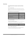
The following table provides a list of the switch types supported by Traffic Analyst and
the approximate time it takes to prepare them for polling.
Switch Type
Estimated Preparation Time
Siemens Hicom 300E and 9751 Models 30 and 80
15 minutes
Siemens 9751 Models 10, 40, 50, 70 and ROLM 9000
15 minutes
Siemens HiPath 3000/Hicom 150
15 minutes
Siemens HiPath 4000
120 minutes
Siemens OpenScape Voice
15 minutes
Nortel SL1 and M1 – All Models
30 minutes
Avaya – All Models
30 minutes
Section 2: Software Installation
This section takes you through installation of Traffic Analyst, which includes the Traffic
Analyst Server and the Web Server Component.
The following table provides the estimated time it takes to install the software.
PC Type
Estimated Preparation Time
Traffic Analyst Server and Web Server Component
10 minutes
Section 3: Installation of Additional Devices
This section covers issues like buffer boxes, FTP Servers and automatically starting
Traffic Analyst. You may be able to skip all of these to Screenshots.
JANUARY 2011
I M P AC T T E CH N O L OG I ES , I N C
CONFI DENTI AL AND PROPRI ETARY
5
T R AF F I C AN AL Y S T I N S T AL L A T I O N G UI D E
Section 1:
Preparation
The preparation required for each type of switch is described in this section.
1.1. Server preparation for the Traffic Analyst Installer
Make sure Internet Information Services (IIS), IIS 7 for windows 2008 is installed on the Traffic Analyst
server.
Make sure .NET Framework 3.5 is installed on the Traffic Analyst server.
Windows 2008 R2 need to “Start” the Application Pool for ASP .NET V2.0 Also “Enable 32-Bit
Applications, this must be set to True. This is set in IIS Application Pool under Advance Settings.
1.2. Siemens HiPath 4000
1.2.1. Pre-Installation Notes
For the Siemens HiPath 4000, Traffic Analyst will pull CDR data from the Unix-side of the
switch. The software will configure the HiPath for data collection. For a list of AMO that
will be configured please contact Impact Technologies Helpdesk. Data collection and switch
configuration uses a TCP/IP connection.
Go to Section 2 titled “Traffic Analyst Software Instructions”. To use this setup you will need
the following:
Access to a PC that is on the same network as the switch
Switch IP Address
Switch Password required
Browser (Microsoft Internet Explorer) on the PC
1.3. Siemens OpenScape Voice
1.3.1. Pre-Installation Notes
For an OpenScape Voice switch, you may need to configure the switch to prepare CDR
data for Traffic Analyst. This is the case if you have more than one OpenScape Voice
switch, or if your OpenScape Voice switch is networked with a HiPath 4000 switch.
Go to your OpenScape Voice Common Management Portal, which you access via a
browser. Log in as “Administrator” with your password. Once you access the software,
go to the OpenScape Voice tab.
Next, select the “Administration” option under the OpenScape Voice tab.
JANUARY 2011
I M P AC T T E CH N O L OG I ES , I N C
CONFI DENTI AL AND PROPRI ETARY
6
T R AF F I C AN AL Y S T I N S T AL L A T I O N G UI D E
From this next tab, choose the “General Settings” option from the list of the left. (If you
have more than one OpenScape Voice switch, choose the appropriate switch and repeat
the following steps for each of the OpenScape Voice.)
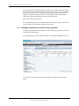
Select the CDR Settings option under General Settings. You will see a Configure CDR
settings window display.
On the Configure CDR settings window, select “Pull” as the “CDR Delivery Method”.
The PISN ID is the same as the Node ID in Traffic Analyst, so you can set those three
fields to anything you wish, but the same three values separated by dashes must be set on
the OpenScape Voice Switch Properties Communication tab in Traffic Analyst for the
Node ID.
JANUARY 2011
I M P AC T T E CH N O L OG I ES , I N C
CONFI DENTI AL AND PROPRI ETARY
7
T R AF F I C AN AL Y S T I N S T AL L A T I O N G UI D E
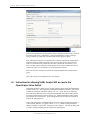
You can check the fields on the Options tab, but they don’t normally need to be changed.
The default of 30 days for the data retention period is good unless you are worried about
disk space and want to lower it. Normally, Traffic Analyst will collect this data daily
regardless, so this data retention period here is only helpful if Traffic Analyst hasn’t
collected for some reason and needs to go back and get older data.
Select “OK” when you are finished.
It is recommended that you set up customer IDs for each business group. For instruction
on how to do this, please continue reading the next section.
1.3.1.1. Creating Customer IDs for Business Groups (optional)
Creating Customer Identification numbers for each business group will allow you to sort
report data by business group.
To edit this information, select “Business Group” from under the OpenScape Voice tab.
Next, select a business group from the list presented by clicking the business group’s
name.
JANUARY 2011
I M P AC T T E CH N O L OG I ES , I N C
CONFI DENTI AL AND PROPRI ETARY
8
T R AF F I C AN AL Y S T I N S T AL L A T I O N G UI D E
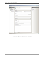
In the
General tab of the Business Group window, find the “Message Detail Records” section at
the bottom of the screen. Complete the “Customer Identification” field by entering a
string of numbers by which you will identify this business group in reports.
Note: Each business group is not required to have a unique Customer ID. Unique IDs are
useful for sorting by business group in reports, however there may be times when you
want two or more business groups tied to the same Customer ID. For instance, if you
have a site that requires using two business groups and you want to identify the site as a
whole in the report, it is acceptable to give both groups the same ID.
Select the “Activate” checkbox to activate the customer identification for this business
group.
Click “OK” when you are finished to save your changes.
1.4. Instructions for allowing Traffic Analyst API access to the
OpenScape Voice Switch
Configuring the OSV to allow access by Traffic Analyst requires using the command line
interface of the OSV. This is started by running the command line interface (CLI) which
is started by running the command “startCli”. Su – srx, sysad. The person following
these instructions must know how to log into the SSH shell of the OSV and have all the
user names and passwords required to use the CLI. Impact Technologies cannot supply
the passwords for a customer site. In the example below, the freeware tool “PUTTY” is
used for the SSH connection.
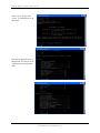
Once a SSH connection is established and the correct user name and password entered, a
system prompt (probably “#”) appears. Enter “su – srx”. Another system prompt then
appears (probablye “$” this time). At this point enter “startCli”. Any entry message with
a “Login:” prompt something like the image below should appear.
JANUARY 2011
I M P AC T T E CH N O L OG I ES , I N C
CONFI DENTI AL AND PROPRI ETARY
9
T R AF F I C AN AL Y S T I N S T AL L A T I O N G UI D E
At the “Login:” prompt, enter
“sysad”. You should then see the
main menu.
Pick option 6,Application-Level
Management. You’ll then see the
Application-Level Management
menu.
JANUARY 2011
I M P AC T T E CH N O L OG I ES , I N C
CONFI DENTI AL AND PROPRI ETARY
10
T R AF F I C AN AL Y S T I N S T AL L A T I O N G UI D E
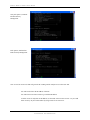
Now pick option 8, Network
Element Security
Management
Pick option 4, Packet Filter
Rules Security Management.
Now we need to create a rule that will given the PC running Traffic Analyst access to the OSV API.
You will need to know the IP address of that PC.
You will also need to enter a mask to go with that IP address.
To allow access for only that one IP address, use the mask value 255.255.255.255. Or you could
allow access by any PC on that subnet by using a mask of 255.255.255.0.
JANUARY 2011
I M P AC T T E CH N O L OG I ES , I N C
CONFI DENTI AL AND PROPRI ETARY
11
T R AF F I C AN AL Y S T I N S T AL L A T I O N G UI D E
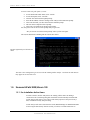
To create a new rule, pick option 1, Create.
• For the Packet Filter Rule Name, enter “Traffic”.
• For the description, enter “TA Rule”.
• Then hit enter at the Remote FQDN prompt.
• Enter the IP address of the PC running Traffic Analyst at the Remote IP prompt.
• Then enter the mask you chose at the Remote NetMask prompt.
• Hit enter at the Transport Protocol prompt.
• Then enter 3 for bothways at the Direction prompt.
You can just hit enter at the rest of the prompt until you get to the
“Do you want to execute this action prompt” where you hit enter again.
The session should look something like the session show below.
Hit enter again and you’ll be back at a
menu.
The OSV is now configured to give access to the PC running Traffic Analyst. Just hit 99 at each menu as
they appear to exit out of the CLI.
1.5. Siemens HiPath 3000/Hicom 150
1.5.1. Pre-Installation Action Items
For these switches, Traffic Analyst does not actually poll the data as in making a
connection to the switch and getting data. Instead the switch constantly sends data that
Traffic Analyst will retrieve. Once a day Traffic Analyst processes the previous day’s
data, in addition to hourly data processing.
Traffic Analyst will retrieve data from the switch, HiPath Manager or HiPath 5000 RSM.
If retrieving the data directly from the switch, you will use a TCP/IP connection. If
JANUARY 2011
I M P AC T T E CH N O L OG I ES , I N C
CONFI DENTI AL AND PROPRI ETARY
12
T R AF F I C AN AL Y S T I N S T AL L A T I O N G UI D E
retrieving the data from HiPath Manager or HiPath 5000 RSM, you may use a TCP/IP
connection or network file access. If you will be retrieving data from HiPath Manager or
HiPath 5000 RSM via TCP/IP, the File Transfer Protocol (FTP) must be used.
If the data is sent via TCP/IP connection, the TCP/IP protocol must be unimpeded. In
particular no router, firewall, or other network device should restrict use. Ask your
network administrator for further details.
Note: Consoles and Console Groups are not supported.
If retrieving data from the switch, HiPath Manager, or HiPath 5000 RSM, there are
settings that must be configured on Hicom Assistant or HiPath Manager or before Traffic
Analyst can poll.
Note: Siemens Hicom 150 is administered by Hicom Assistant or HiPath Manager.
Siemens HiPath 3000 is administered by HiPath Manager.
Note: Only OfficeCom and OfficePro are supported when using Hicom Assistant.
Below are the settings for Hicom Assistant or HiPath Manager.
1.5.1.1. Configure Call Charges Output Format
When configuring the call charges output format, make sure the Format of Call Records section is
filled out as such:
Compressed Output – checked
Last 4 digits suppresses – optional
Log incoming calls – checked
JANUARY 2011
I M P AC T T E CH N O L OG I ES , I N C
CONFI DENTI AL AND PROPRI ETARY
13
T R AF F I C AN AL Y S T I N S T AL L A T I O N G UI D E
Call Duration – checked
On Ringing – checked (option not available in Hicom Assistant)
Output MSN – unchecked
Decimal Format – checked
Display amounts instead of units – unchecked
Outgoing without connection – checked
Output LCR number outgoing or dialed number incoming – unchecked
Next, in the Output format dropdown (located in the CDR systems section of the window), select
LAN-TCP-Client (or None if using HiPath 5000 RSM).
You must click the Apply button to save the changes. (All changes must be sent to the HiPath
before data collection can begin.)
Click the Lan settings… button to access the following display:
The LAN settings must be as follows:
TCP-Client – selected
IP-Addr – IP address of the Traffic Analyst server (or of the HiPath 5000 RSM)
(port) – 27069 (This is the switch port. If this must be something different please contact
Impact Technologies for assistance.)
File format – DOS
JANUARY 2011
I M P AC T T E CH N O L OG I ES , I N C
CONFI DENTI AL AND PROPRI ETARY
14
T R AF F I C AN AL Y S T I N S T AL L A T I O N G UI D E
Separator - ;
You must click the Apply button to save the changes.
If retrieving data from HiPath 5000 RSM, it must be configured to receive CDR data
from the switch.
When the above activities are done, go to the section entitled “Traffic Analyst Software
Installation”.
1.6. Siemens Hicom 300E and 9751 Models 30 and 80
1.6.1. Pre-Installation Notes
Note: For normal data collection, Traffic Analyst will poll the Siemens Hicom 300 switches
and 9751 Model 30 and 80 switches once a day, usually in the early morning hours. Up to ten
days of data may be stored and available on the UNIX partition of the switch.
Note: For CDR data collection, available only with the web-based version of Traffic Analyst
and the purchase of the CDR module, Traffic Analyst will retrieve data from a buffer box
once or more than once per hour.
Note: If the switch is a Siemens 9006.6 there will already be an FTP user name and
password defined. Username = tal and password = tal, and will be used only if Traffic
Analyst will be connecting to the switch using TCP/IP (LAN connection).
Note: Traffic Analyst can alternately connect using TCP/IP to a Siemens 9006.6 switch
under the following conditions:
1.
The switch must have a network daughter board installed and LAN
connectivity configured and enabled.
2.
The TCP/IP protocol must be unimpeded between the Traffic Analyst
system and the Switch. In particular no router, firewall, or other network
device should restrict the use of the well-known FTP ports. Ask your
network administrator for further details.
Note: If previous traffic studies have been run using BELAU, you should delete these
studies before polling with Traffic Analyst. Use the AMO “belin” to delete these studies.
1.6.2. Installation Instructions
As you complete each of the following activities, put a check mark in the box next to
each of the following items:
1.6.2.1. Confirming the Switch Software Release
Software release 9006.3 with SMR6 or a later version must be installed on the switch. The
software release must be installed on the switch before Traffic Analyst can poll. Confirm that
the software is installed on the switch.
JANUARY 2011
I M P AC T T E CH N O L OG I ES , I N C
CONFI DENTI AL AND PROPRI ETARY
15
T R AF F I C AN AL Y S T I N S T AL L A T I O N G UI D E
1.6.2.2. Obtain Switch Username & Password
Obtain the switch user name and password that must be defined and available for Traffic
Analyst to log-on to the switch. The username and password must provide access to the
"UDSC" menu and contain the LTDR (List Traffic Data Retrieval) option. It is OK if other
menu options also appear. Suggested to use the rsca username.
1.6.2.3. Running the AMO Command
The following AMO command should be performed on the RMX side of the switch unless the
switch is a Siemens 9006.6. This command starts up LTDR and the associated traffic
metering on the switch:
exec-xapc:A1,"act.ltdr -save 10";
The number 10 in the above command represents the number of days of traffic data that will
be stored on the Unix partition of the switch. It can be a value from 1 to 10. If there is any
concern that the Unix partition on the switch may be low on disk space, then reduce this
number to 3. Please note that in the above command, there are spaces between “ltdr” and the
“–save”, and again between “-save” and “10”. The command does end with a semi-colon.
If the switch is a Siemens 9006.6, LTDR is automatically on and set to store 10 days by
default.
1.6.2.4. Obtaining a Serial Connection to the Switch
Obtain a Unix switch serial port that will be available for the traffic server to use. If you are using
your switch’s LAN connection, then see below. Traffic can use a dial-up or direct connection.
Traffic will connect with the switch once a day, usually in the early morning, for approximately 20
minutes to an hour. The connection to the Traffic computer can be over a modem (US Robotics
Sportster 56K is recommended), a data line or via direct RS-232 cable. Traffic can work with
LeeMah keys, if they are in place.
Note: When the above activities are done, go to the section entitled “Traffic Analyst
Software Installation”.
1.7. Siemens 9751 Models 10, 40, 50, 70 and ROLM 9000
1.7.1. Pre-Installation Notes
For these switches, Traffic Analyst will poll once a day, usually in the early morning hours
for the previous day’s data. The day’s data consists of interval-by-interval results for 50
intervals. The interval length is defined on the switch and we recommend 1 hour intervals.
Traffic Analyst issues the LIST TRAF ALL ALL PAST ALL command to get the following
data:
•
•
JANUARY 2011
trunk groups
console groups
I M P AC T T E CH N O L OG I ES , I N C
CONFI DENTI AL AND PROPRI ETARY
16
T R AF F I C AN AL Y S T I N S T AL L A T I O N G UI D E
•
•
•
•
•
•
•
•
•
•
consoles
lines
internode or INL
tone senders
DTMF registers
rotary senders
conference bridges
event and peg counts
PhoneMail
system information
After polling, the data is parsed and stored into hourly results in the Traffic Analyst database.
1.7.2. Installation Instructions
As you complete the following activities, put a check mark in the box next to each of the
following items:
1.7.2.1. Confirming the Switch Software Release
Software release 9004.0.38 or later must be installed on the switch. The software release must be
installed on the switch before Traffic Analyst can poll. Confirm that the software is installed on
the switch.
1.7.2.2. Obtain Switch Username & Password
A CLI User name and password must be defined and available for Traffic Analyst to log on
with. It should provide access to the following commands:
LIST TRUNK_GROUP NAME (In Config)
LIST TRAF
LIST ATC_GROUP ALL (optional) (In Config)
1.7.2.3. Obtaining a Serial Connection to the Switch
A serial port on the switch must be made available for the traffic server to log onto. Traffic will
connect with the switch once a day, usually in the early morning, for approximately 20 minutes to
an hour, although large model 70s can take multiple hours. The connection to the Traffic computer
can be over a modem, a data line or via direct RS-232 cable, for Model 70’s we recommend a
direct RS-232 connection. Traffic can work with LeeMah keys, if they are in place.
JANUARY 2011
I M P AC T T E CH N O L OG I ES , I N C
CONFI DENTI AL AND PROPRI ETARY
17
T R AF F I C AN AL Y S T I N S T AL L A T I O N G UI D E
1.8. Nortel SL1 and M1 – All Models
1.8.1. Pre-Installation Notes (Call Accounting)
For CDR data, Nortel switches create CDR files that can be pulled from the switch using FTP.
Alternatively, the CDR data can be streamed to a buffer box, with the data being pulled from
the buffer box using FTP.
The CDR parameters should be set to output the “New” SL-1 CDR format. This corresponds
to setting the FCDR in LD 17 to “NEW”.
NOTE: If CDR has not already been configured on your switch, we recommend you request
support from your switch manufacturer to help set up your switch for CDR output. Or, you
may also want to reference Nortel’s Call Detail Recording System Administration Guide.
1.8.2. Pre-Installation Notes (Network)
For Network data on Nortel switches, data must be polled or captured every interval or it will
be lost. Intervals are defined on the switch and can be an hour or ½ hour in length. Traffic
Analyst can directly poll the switch on an interval-by-interval basis, or it can work with a
variety of buffer boxes to get the data. If buffer boxes are used, multiple days worth of past
data may be available for polling.
Traffic uses Load 2 to get and store the following traffic data reports (the switch report
numbers are in parenthesis):
•
•
•
•
•
•
•
•
•
•
•
•
•
Network (TFC001)
Trunk Group (TFC002)
Console Group (TFC003)
Console Member (TFC004)
Feature (TFC005)
Network Loop (TFS001)
Service (TFS002)
Dial Tone Delay (TFS003)
Processor (TFS004)
Selected Terminal (TFS005)
Junctor (TFS007)
IP Phone Zone Traffic (TFS016)
DSP Peg Count (TFC012)
After polling, the Network data is parsed and stored into hourly results in the Traffic Analyst
database.
1.8.3. Installation Instructions
As you complete the following activities, put a check mark in the box next to each of the
following items:
JANUARY 2011
I M P AC T T E CH N O L OG I ES , I N C
CONFI DENTI AL AND PROPRI ETARY
18
T R AF F I C AN AL Y S T I N S T AL L A T I O N G UI D E
1.8.3.1. Configuring the Switch
Traffic data is the only data that should be configured on the port. CDR, alarms, and
maintenance messages must be output to a separate port from the LD 2 traffic data. The
data streams cannot be sent to the same port.
1.8.3.1.1. Choose the Type of Configuration
1.8.3.1.1.1. Polling Directly from the Switch via Serial Port
If Traffic is polling the switch (rather than a buffer box), and the switch is release 23 or
less, then a serial port must be configured for access and a password must be available for
Traffic to log on with. LD 2 must be accessible from this port. If the switch is release 25
or higher or Succession 3.0, 4.0, 5.0 connection can be made via serial or TCP/IP.
1.8.3.1.1.2. Polling Directly from the Switch via TCP/IP using FTP
If the switch is release 25 or higher or Succession, then Traffic Analyst can communicate
to the switch via TCP/IP using File Transfer Protocol (FTP). Data will be retrieved from
the switch disk. The FTP protocol must be unimpeded and the switch login requires a
Debug username and password. It is required to have DBA-Package 351. Follow the
below commands on the switch.
To enable output of traffic data to the disk (buffer): (Up to 2 MB of data will store
on the disk.)
LD117 ENL BUF TRF
To verify outputs of traffic data is enabled:
LD117 STAT BUF
The below status should reply.
TRF ENL
The switch must then be configured to send the LD2 data.
1.8.3.1.1.3. Polling Directly from the Switch via Rlogin
For rlogin access:
Username: This should be CPSIDnnnn where nnnn are combinations of
zero or ones.
IP or hostname of the switch: Network IP address to the switch.
Note: no password is required
For interactive shell access, Level1 or Level2:
Username
Password
1.8.3.1.1.3.1. Traffic Analyst Interaction
Following is the interaction Traffic Analyst will programmatically have with the Nortel
switch each hour. With the exception of the first and last step, these represent the same
JANUARY 2011
I M P AC T T E CH N O L OG I ES , I N C
CONFI DENTI AL AND PROPRI ETARY
19
T R AF F I C AN AL Y S T I N S T AL L A T I O N G UI D E
steps used by Traffic Analyst with a serial connection or IP connection using a Lantronix
UDS-10 terminal server.
•
•
Establish the rlogin session with the Nortel switch. “rlogin –l CPSIDnnnn
nnn.nnn.nnn.nnn” where the four digits after “CPSID” are a set of ones and zeros,
and nnn.nnn.nnn.nnn is the IP Address of the Nortel switch.
Once the rlogin connection is established enter a <Return> to launch the Nortel
interactive shell. Login using your level 1 or level 2 password:
>LOGI <respond with username>
•
•
•
•
•
•
PASS? <respond with password>
After the log-in confirmation message type a return.
At “>” prompt enter: LD 2
At ”.” prompts invoke Load 2 commands to retrieve traffic data, such as:
. Invc 0 2
. Invc 0 3
. Invs 1
When finished with Load 2 commands type four (4) asterisks “****”.
At “>” prompt type LOGO to logout.
Drop the rlogin connection.
These commands can be performed by hand for confirmation. The first step with require
third party software (such as SecureCRT) to establish the rlogin connection. Depending
on the software used the input sequence of the rlogin process may differ from that shown
above.
1.8.3.1.1.4. Polling Directly from the Switch via SSH
If the switch is Succession 6.0 or higher Traffic Analyst can communicate to the switch
via SSH.
For SSH access:
Username: This should be CPSIDnnnn where nnnn are combinations of
zero or ones.
IP or hostname of the switch: Network IP address to the switch.
Note: no password is required
For interactive shell access, Level1 or Level2:
Username
Password
1.8.3.1.1.4.1. Traffic Analyst Interaction
Following is the interaction Traffic Analyst will programmatically have with the Nortel
switch each hour.
•
JANUARY 2011
Once the SSH connection is established enter a <Return> to launch the Nortel
interactive shell. Login using your level 1 or level 2 password:
>LOGI <respond with username>
I M P AC T T E CH N O L OG I ES , I N C
CONFI DENTI AL AND PROPRI ETARY
20
T R AF F I C AN AL Y S T I N S T AL L A T I O N G UI D E
•
•
•
•
•
PASS? <respond with password>
After the log-in confirmation message type a return.
At “>” prompt enter: LD 2
At ”.” prompts invoke Load 2 commands to retrieve traffic data, such as:
. Invc 0 2
. Invc 0 3
. Invs 1
When finished with Load 2 commands type four (4) asterisks “****”.
Drop the SSH connection.
These commands can be performed by hand for confirmation. The first step with require
third party software (such as SecureCRT) to establish the rlogin connection. Depending
on the software used the input sequence of the SSH process may differ from that shown
above.
1.8.3.1.1.5. Polling from a Buffer Box
If you are using a buffer box, it must be configured properly. The switch must be
configured to output its LD 2 data to the buffer box. The buffer box must be configured
so that Traffic can access the data. Buffer boxes support a variety of connectivity and
output options, from serial (modem) access to TCP/IP using FTP or Telnet support. See
the section entitled “Working With Buffer Boxes” later in this document for a list of
buffer boxes supported and information on configuring them for access by Traffic
Analyst.
1.8.3.1.2. Running the Switch Command for LD 2
To prepare your switch to send the LD2 data to the port, you will need to type the
following at a command prompt on the switch:
SSHS [Enter]
1 1 31 12
the first 2 digits represent the beginning date and the last 2 the
ending date. (1/1 – 12/31 = all year)
0 23 1
the first 2 digits represent the times of storage and the last is the
interval. (Midnight to Midnight and 1 hour intervals)
1234567
these numbers represent the days of the week to be stored.
(Sunday – Saturday)
SSHC [Enter]
JANUARY 2011
1 1 31 12
the first 2 digits represent the beginning date and the last 2 the
ending date. (1/1 – 12/31 = all year)
0 23 1
the first 2 digits represent the times of storage and the last is the
interval. (Midnight to Midnight and 1 hour intervals)
I M P AC T T E CH N O L OG I ES , I N C
CONFI DENTI AL AND PROPRI ETARY
21
T R AF F I C AN AL Y S T I N S T AL L A T I O N G UI D E
1234567
these numbers represent the days of the week to be stored.
(Sunday – Saturday)
Note: When the above activities are done, go to the section entitled “Traffic Analyst
Software Installation”.
1.9. Avaya – All Models
1.9.1. Pre-Installation Notes
Avaya switch CDR data is retrieved either from the switch’s hard disk (called Survivable
CDR) or the CDR may be streamed to a buffer box. CDR parameters should be
configured to output CDR in the “Expanded” format.
NOTE: If CDR has not already been configured on your switch, we recommend you request
support from your switch manufacturer to help set up your switch for CDR output.
Avaya switch Network data is retrieved using the ASA (Avaya Site Administration) tool.
There are 2 steps to prepare the ASA to collect data from the switch, Defining A Voice
System Connection and Data Collection Scheduling. All data is retrieved from the
switch using ASA and stored on the local hard drive or network drive. Traffic Analyst
then uses these files to create data. A decision as to the frequency of when data will be
collected, hourly or daily, needs to be made before switch setup and then Traffic Analyst
will have to be setup accordingly. If data will be polled hourly, the trunk groups need a
flag turned on to allow hourly measurements.
NOTE: ASA must be running at all times for Network data collection from the switch to
occur.
1.9.2. Installation Instructions (Call Accounting)
After CDR data collection is set-up on your switch, you will need to activate retrieval of
it in the Traffic Analyst Administrative Tool. You can do this on the Communications
screen while setting up your switch. On the bottom portion of this screen, you will
designate where the CDR data is being retrieved from. For detailed instructions on setting
up your Avaya switch in Traffic Analyst, please see the section entitled “Avaya Data
Directory Communications” in the Traffic Analyst Administrative Guide.
1.9.3. Installation Instructions (Network)
As you complete the following activities, put a check mark in the box next to each of the
following items:
1.9.3.1. Configuring ASA (Avaya Site Administration)
This configuration has 2 steps, Defining A Voice System Connection and Data
Collection Scheduling (Hourly or Daily).
1.9.3.1.1. Defining A Voice System Connection
Define the connection.
JANUARY 2011
I M P AC T T E CH N O L OG I ES , I N C
CONFI DENTI AL AND PROPRI ETARY
22
T R AF F I C AN AL Y S T I N S T AL L A T I O N G UI D E
JANUARY 2011
1.
Start ASA and select File | New Voice System.
2.
Choose Add New Voice System and select OK.
I M P AC T T E CH N O L OG I ES , I N C
CONFI DENTI AL AND PROPRI ETARY
23
T R AF F I C AN AL Y S T I N S T AL L A T I O N G UI D E
3.
Enter a Voice System Name and select Next.
4.
Choose the type of connection used to communicate with the switch then select
Next.
Modem or data module
Direct serial port connection
Network connection
a)
For Modem or data module connection:
Choose Device from the drop-down list and select Next.
JANUARY 2011
I M P AC T T E CH N O L OG I ES , I N C
CONFI DENTI AL AND PROPRI ETARY
24
T R AF F I C AN AL Y S T I N S T AL L A T I O N G UI D E
Choose the appropriate Port from the drop-down list and select Next.
Choose the appropriate Port Settings for the communication device
and select Next.
JANUARY 2011
I M P AC T T E CH N O L OG I ES , I N C
CONFI DENTI AL AND PROPRI ETARY
25
T R AF F I C AN AL Y S T I N S T AL L A T I O N G UI D E
Enter the Phone Number of the switch to be dialed, making sure to
include any outside access numbers if necessary, then select Next.
Leave this screen at the default values and select Next.
b) For Direct serial port connection:
JANUARY 2011
I M P AC T T E CH N O L OG I ES , I N C
CONFI DENTI AL AND PROPRI ETARY
26
T R AF F I C AN AL Y S T I N S T AL L A T I O N G UI D E
Choose the appropriate Port from the drop-down list and select Next.
Choose the appropriate Port Settings for the communication device
and select Next.
c)
JANUARY 2011
For Network connection:
I M P AC T T E CH N O L OG I ES , I N C
CONFI DENTI AL AND PROPRI ETARY
27
T R AF F I C AN AL Y S T I N S T AL L A T I O N G UI D E
Enter the FQDN or IP address of the switch.
Accept the default TCP/IP Port Number of 23 and select Next.
JANUARY 2011
I M P AC T T E CH N O L OG I ES , I N C
CONFI DENTI AL AND PROPRI ETARY
28
T R AF F I C AN AL Y S T I N S T AL L A T I O N G UI D E
Accept the defaults and select Next.
5.
Choose I want Avaya SA to log me in automatically.
Select Next.
6.
JANUARY 2011
Enter the Login ID (Super-user permissions) and choose either Password or
ASG radio button.
I M P AC T T E CH N O L OG I ES , I N C
CONFI DENTI AL AND PROPRI ETARY
29
T R AF F I C AN AL Y S T I N S T AL L A T I O N G UI D E
Select Next.
JANUARY 2011
I M P AC T T E CH N O L OG I ES , I N C
CONFI DENTI AL AND PROPRI ETARY
30
T R AF F I C AN AL Y S T I N S T AL L A T I O N G UI D E
a)
For Password option:
Enter Password then select Next.
b) For ASG option:
Enter Secret Key and select Next.
JANUARY 2011
I M P AC T T E CH N O L OG I ES , I N C
CONFI DENTI AL AND PROPRI ETARY
31
T R AF F I C AN AL Y S T I N S T AL L A T I O N G UI D E
7.
Review the Summary Screen.
Select Test to attempt the connection with the switch. If test fails, make
appropriate changes to the communications until the test is successful then select
Next.
8.
JANUARY 2011
Select Finish to complete the setup.
I M P AC T T E CH N O L OG I ES , I N C
CONFI DENTI AL AND PROPRI ETARY
32
T R AF F I C AN AL Y S T I N S T AL L A T I O N G UI D E
1.9.3.1.2. Data Collection Scheduling
Data Collection may be scheduled daily or hourly with Traffic Analyst. Data
collection will be scheduled hourly when an hourly alarm is assigned to a switch.
Follow the appropriate instructions below based on how data collection is scheduled
within Traffic Analyst.
1.9.3.1.2.1. Hourly Scheduling
Four reports must be polled from the switch in order to perform Hourly Polling of Traffic
Analyst. They are summarized below:
Traffic Data Reports
Report
aca-parameters
trunk-group summary
Data Description
Trunk Group listing.
Hourly summary of traffic on all trunk groups except Personal
Central Office Line Groups.
Alarm Reports
Report
outage-trunk
lightly-used-trunk
Data Description
Lists a maximum of five trunks in each group that were out of
service when sampled.
Lists the five trunk members with the lowest number of calls.
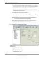
Scheduling Hourly Reports
JANUARY 2011
1.
Open ASA.
2.
If more than one switch is defined select System | Target System.. | <desired switch>
3.
In the Tasks tab, under the Advanced section, click on Report.
I M P AC T T E CH N O L OG I ES , I N C
CONFI DENTI AL AND PROPRI ETARY
33
T R AF F I C AN AL Y S T I N S T AL L A T I O N G UI D E
4.
In the Command(s) field enter:
list measurements trunk-group hourly <group #>;list aca-parameters;list
measurements outage-trunk last-hour;list measurements lightly-used-trunk last-hour;
Note: The first command “list measurements trunk-group hourly <group>;” must be
entered for each trunk group.
Example:
A switch has 5 trunk groups with trunk group number 1,2,3,10,15. The Command(s)
list would be:
list measurements trunk-group hourly 1; list measurements trunk-group hourly
2;list measurements trunk-group hourly 3;list measurements trunk-group
hourly 10;list measurements trunk-group hourly 15;list aca-parameters;list
measurements outage-trunk last-hour;list measurements lightly-used-trunk
last-hour;
The first command “list measurements trunk-group hourly <group #>” must be enter
for each trunk group.
JANUARY 2011
5.
Select Export fields to file then select OK.
6.
Select Append to existing file.
7.
Select Append to existing file always.
I M P AC T T E CH N O L OG I ES , I N C
CONFI DENTI AL AND PROPRI ETARY
34
T R AF F I C AN AL Y S T I N S T AL L A T I O N G UI D E
8.
Select the Browse (…) button next to Export to file field.
9.
Select Append to existing file.
10. Select the Browse (…) button next to Export file field.
11. Change the File name to hourlydata.txt. If multiple switches, either create a
separate folder for each switch or make the filename unique (e.g.
ChicagoHourlyData.txt, BostonHourlyData.txt, etc.).
JANUARY 2011
I M P AC T T E CH N O L OG I ES , I N C
CONFI DENTI AL AND PROPRI ETARY
35
T R AF F I C AN AL Y S T I N S T AL L A T I O N G UI D E
12. Select the target directory from which Traffic Analyst will retrieve the file.
13. Select Open.
14. Select OK.
15. Select OK.
JANUARY 2011
I M P AC T T E CH N O L OG I ES , I N C
CONFI DENTI AL AND PROPRI ETARY
36
T R AF F I C AN AL Y S T I N S T AL L A T I O N G UI D E
16. Enter the desired start date. This should be the first date you want to start doing
Traffic analysis.
17. Enter a 12:10:00 AM for the Time. If your start date is today you will need to
readjust the time of day to be 10 minutes after the next hour. This allows the switch
time generate the data for the previous time interval. So if it is currently 1:40 PM set
the time to 2:10:00 PM.
18. Select Frequent as the Recurrence Pattern.
19. Enter Every 1 hour(s) and 0 minute(s).
20. Select Disconnect from system after task has been processed.
21. Select OK.
1.9.3.1.2.2. Daily Scheduling
Four reports must be polled from the switch in order to perform Daily Polling of Traffic
Analyst. They are summarized below:
Traffic Data Reports
Report
aca-parameters
trunk-group hourly
Data Description
Trunk Group listing.
24 Hour summary of traffic on all trunk groups. Must be run
for each Trunk Group
Alarm Reports
Report
outage-trunk
lightly-used-trunk
JANUARY 2011
Data Description
Lists a maximum of five trunks in each group that were out of
service when sampled.
Lists the five trunk members with the lowest number of calls.
I M P AC T T E CH N O L OG I ES , I N C
CONFI DENTI AL AND PROPRI ETARY
37
T R AF F I C AN AL Y S T I N S T AL L A T I O N G UI D E
Scheduling Daily Reports
1.
Open ASA.
2.
If more than one switch is defined select System | Target System.. | <desired switch>
3.
In the Tasks tab, under the Advanced section, click on Report.
4.
In the Command(s) field enter:
list measurements trunk-group hourly <group#>;list aca-paramenters;list
measurements outage-trunk yesterday;list measurements lightly-used-trunk yesterday
Note: The first command “list measurements trunk-group hourly <group>;” must be
entered for each trunk group.
Example:
A switch has 5 trunk groups with trunk group number 1,2,3,10,15. The Command(s)
list would be:
list aca-parameters;list measurements trunk-group hourly 1;list measurements
trunk-group hourly 2;list measurements trunk-group hourly 3;list
measurements trunk-group hourly 5;list measurements trunk-group hourly
11;list measurements trunk-group hourly 41;list measurements outage-trunk
yesterday;list measurements lightly-used-trunk yesterday
JANUARY 2011
I M P AC T T E CH N O L OG I ES , I N C
CONFI DENTI AL AND PROPRI ETARY
38
T R AF F I C AN AL Y S T I N S T AL L A T I O N G UI D E
5.
Select Export fields to file.
6.
Select Append to existing file.
7.
Select Append to existing file always.
8.
Select Browse (…) next to the Export to file field.
9.
Select Append to existing file.
10. Select Browse (…) next to the Export file field.
JANUARY 2011
I M P AC T T E CH N O L OG I ES , I N C
CONFI DENTI AL AND PROPRI ETARY
39
T R AF F I C AN AL Y S T I N S T AL L A T I O N G UI D E
11. Change File name to dailydata.txt. If multiple switches, either create a separate
folder for each switch or make the filename unique (e.g. ChicagoDailyData.txt,
BostonDailyData.txt, etc.).
12. Select the target directory from which Traffic Analyst will retrieve the file.
13. Select Open.
14. Select OK.
15. Select OK.
16. Enter the desired start date (tomorrow or later). This should be the first date you
want to start doing Traffic analysis.
JANUARY 2011
I M P AC T T E CH N O L OG I ES , I N C
CONFI DENTI AL AND PROPRI ETARY
40
T R AF F I C AN AL Y S T I N S T AL L A T I O N G UI D E
17. Enter 12:15:00 AM for the Time. You will need to adjust the time of day if the
switch is in a different time zone. You will want to poll 15 minutes after midnight on
the switch.
18. Select Weekly for the Recurrence Pattern.
19. Select all days of the week.
20. Select Disconnect from system after task has been processed.
21. Select OK.
1.10. Cisco Unified Communications Manager
1.10.1. Pre-Installation Notes
For a Cisco Unified Communications Manager switch, you need to make sure the switch
is properly configured to prepare CDR data for Traffic Analyst. This involves
configuring the Cisco Communication Manager Administration, as well as the Cisco
CDR Repository Manager.
1.10.1.1. Cisco Communication Manager Administration
Go to the Cisco Communications Manager Administration tool, which you access via a
web browser. Once you access the software, go to System > Service Parameters.
Select a server, if needed, as well as the service Call Manager (active). Note: All
parameters except cluster-wide parameters must be set for each server. If you don’t see
the parameters described below, choose the Advanced button to display the complete list
of Service Parameters.
Under System Parameters, set the CDR Enabled Flag to true.
The CDR Log Calls With Zero Duration Flag can be left set to false, though it can also
be set to true if you want to see these records in your CDR reports.
Under Clusterwide Parameters (Device – General), if Traffic Analyst Call Accounting
reports are licensed, we recommend setting Call Diagnostics Enabled to enabled and
Show Line Group Member DN in finalCalledPartyNumber CDR Fields to true.
The Display FAC in CDR setting is up to the user but only appears in Traffic Analyst if
Call Accounting is licensed.
The Add Incoming Number Prefix to CDR, located under Clusterwide Parameters
(Device – Phone), is also up to the user’s preference but only appears in Traffic Analyst
if Call Accounting is licensed.
Next, from the main Cisco Communication Manager Administration window, select
System > Enterprise Parameters.
CDR File Time Interval should be left at the default value of 1 minute.
JANUARY 2011
I M P AC T T E CH N O L OG I ES , I N C
CONFI DENTI AL AND PROPRI ETARY
41
T R AF F I C AN AL Y S T I N S T AL L A T I O N G UI D E
If you are using Traffic Analyst for more than one cluster, make sure that Cluster ID is
set to a unique string of characters.
The other CDR settings under Enterprise Parameters do not apply to Traffic Analyst’s
CDR processing.
1.10.1.2. Cisco CDR Repository Manager
The Cisco Unified Communication Manager sends CDR files to the Cisco CDR
Repository Manager which then distributes the files to other applications.
To configure the Cisco CDR Repository Manager, open Cisco Unified Serviceability.
Choose Tools > CDR Management.
The General Parameters can be left at their default values.
Under the Billing Application Server Parameters, click on the Add New button to add
a new Billing Application Server.
Enter or modify all the parameters for the FTP server to which you want the CDR files
sent:
• Host Name/ IP Address
• User Name
• Directory Path.
Choose FTP for the Protocol.
Note: Traffic Analyst collects CDR data from a user-supplied FTP server where the
Cisco Communications Manager deposits the files. If you are installing Traffic Analyst
Advanced, the FTP server that is included with Microsoft IIS can be used. For maximum
reliability, we recommend a dedicated FTP server, or even a non-disk based FTP server
such as a Scannex ip.buffer buffer box.
JANUARY 2011
I M P AC T T E CH N O L OG I ES , I N C
CONFI DENTI AL AND PROPRI ETARY
42
T R AF F I C AN AL Y S T I N S T AL L A T I O N G UI D E
Section 2:
Traffic Analyst Software Installation
Before installing the software, the switch(es) should be prepared for polling.
Make sure all required Windows components have been installed. It is advised to double
check for these.
•
.Net Framework 3.5 or greater
•
IIS or IIS 7 if using Windows 2008
Important Note: You must have administrative privileges to successfully install. Log in
to Windows with an administrative user name and password before beginning the
installation.
Traffic Analyst can be licensed as a stand-alone program on a single computer, or it can
be configured for a client-server environment.
In a client-server environment, you install Traffic Analyst on both server and clients, but
there are slightly different installation steps. All switch polling and database storage is
done on the server. Clients have a few of the functionality that can be performed from the
server, but there are some slight delays that occur with real-time updates during switch
polling. You should install the main server first, before any clients.
Before installing the software, the switch(es) should be prepared for polling.
Important Note for Windows 2003, 2008: You must have administrative privileges to
successfully install. Log onto Windows with an administrative user name and password
before beginning the installation.
Important Notes for Windows 7, 2008, Vista: The ISAPI Redirector (provided by
Tomcat) is no longer reliable enough to work on newer releases of IIS 7. Microsoft has
stated that the ISAPI Redirectors should be phased out. Applications that depend on this
feature should use ARR (Application Request Routing) instead. ARR is an extension
module for IIS 7. There are special instructions for configuring TrafficWeb to work with
newer versions of IIS 7, using ARR. See Configuring IIS with ARR (Windows 7, 2008,
Vista) in the Appendix for instructions.
Also, for full functionality, you may need to make sure that install directories are set to
“Full Control.”
2.1. Installing a Traffic Analyst Server or client
Follow the steps below to install a Traffic Analyst configuration. Please note that if the
Setup program finds DLL files on your system that are older than the DLLs it will install,
it asks you if you want to replace them. Select the "Install new and keep old DLL" option
in this event.
Put the CD you received from Impact Technologies in your CD drive. Or, if you are
installing from a network directory, locate the directory where the Impact Technologies
CD has been copied.
JANUARY 2011
I M P AC T T E CH N O L OG I ES , I N C
CONFI DENTI AL AND PROPRI ETARY
43
T R AF F I C AN AL Y S T I N S T AL L A T I O N G UI D E
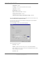
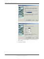
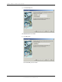
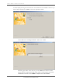
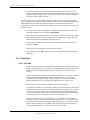
Run the ImpactInstall.exe program. Note: If using Windows Server 2008, right-click
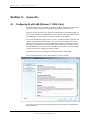
ImpactInstall.exe and select “Run as Administrator.” This is done so that proper
security access is given to the install process.
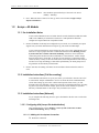
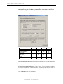
The following windows appears:
Licensed
Application Server
OnTraQ link
Web Server
OnTraQ Application
Server
OnTraQ Client
Network
Console
CDR
OnTraQ
X
X
X
X
X
X
X
X
OnTraQ Application Server must be installed on the same server as CAP Management.
Silent Mode – check if all defaults are preferred
You must select an operating system. 32 bit or 64 bit. If you are not sure go to Start –
Accessories-System Tools – System Information System Type will tell you if 32 bit or
64 bit. X86 based PC = 32 bit
Click on Install for first time installation.
JANUARY 2011
I M P AC T T E CH N O L OG I ES , I N C
CONFI DENTI AL AND PROPRI ETARY
44
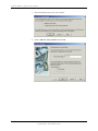
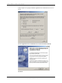
T R AF F I C AN AL Y S T I N S T AL L A T I O N G UI D E
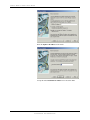
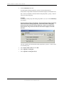
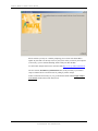
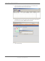
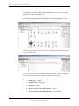
In this example we are going to install the Application Server and Web Service on a 32
bit OS.
Click on Application Server and Web Service, 32 bit OS and click on Install
Click Next
JANUARY 2011
I M P AC T T E CH N O L OG I ES , I N C
CONFI DENTI AL AND PROPRI ETARY
45
T R AF F I C AN AL Y S T I N S T AL L A T I O N G UI D E
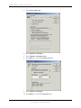
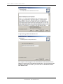
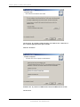
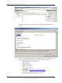
Accept license agreement and click on Next
The computer name will append to the default database name Database-ServerImpact, it is suggested to accept this name and click Next. If you change the name
just make a note of the new name as you can not have two installations with the
same database name.
JANUARY 2011
I M P AC T T E CH N O L OG I ES , I N C
CONFI DENTI AL AND PROPRI ETARY
46
T R AF F I C AN AL Y S T I N S T AL L A T I O N G UI D E
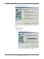
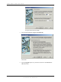
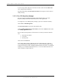
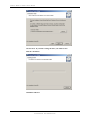
Click on Next. If you need to change the drive you will do so here.
Must be a local drive.
Installation will start.
JANUARY 2011
I M P AC T T E CH N O L OG I ES , I N C
CONFI DENTI AL AND PROPRI ETARY
47
T R AF F I C AN AL Y S T I N S T AL L A T I O N G UI D E
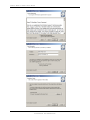
The first step has completed now it will start the application installation.
Click on Next
JANUARY 2011
I M P AC T T E CH N O L OG I ES , I N C
CONFI DENTI AL AND PROPRI ETARY
48
T R AF F I C AN AL Y S T I N S T AL L A T I O N G UI D E
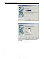
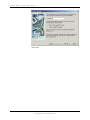
Accept the license agreement and click on Next
Click on Next
JANUARY 2011
I M P AC T T E CH N O L OG I ES , I N C
CONFI DENTI AL AND PROPRI ETARY
49
T R AF F I C AN AL Y S T I N S T AL L A T I O N G UI D E
Click on Next. If you need to change the drive you will do so here. Must select a
drive with the appropriate disk space available.
Must be a local drive.
Default is 512. If you have 2 GB RAM enter 1024, IF 3GB RAM enter in 1536.
Click on Next
JANUARY 2011
I M P AC T T E CH N O L OG I ES , I N C
CONFI DENTI AL AND PROPRI ETARY
50
T R AF F I C AN AL Y S T I N S T AL L A T I O N G UI D E
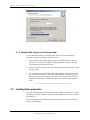
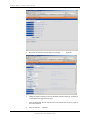
Application server is now completed. See Section 2.2 “Installing Web Application” for
step by step instructions.
The other components selected for installations will start now. When completed the
Install Utility Screen will appear. All installed components are now displayed in “Bold”
letters.
JANUARY 2011
I M P AC T T E CH N O L OG I ES , I N C
CONFI DENTI AL AND PROPRI ETARY
51
T R AF F I C AN AL Y S T I N S T AL L A T I O N G UI D E
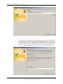
2.1.1. Installing Traffic Analyst Client on Workstation
Before installing the client software you will need to know the database name of the database
installed on Traffic Analyst server. Also IP or Host name of the server where the database is
running.
Copy the TrafficAnlaystClientSetup.msi file from the Install CD to the workstation for
installation.
Follow the install wizard:
JANUARY 2011
I M P AC T T E CH N O L OG I ES , I N C
CONFI DENTI AL AND PROPRI ETARY
52
T R AF F I C AN AL Y S T I N S T AL L A T I O N G UI D E
JANUARY 2011
I M P AC T T E CH N O L OG I ES , I N C
CONFI DENTI AL AND PROPRI ETARY
53
T R AF F I C AN AL Y S T I N S T AL L A T I O N G UI D E
2.1.2. Adding Traffic Analyst to the Startup Folder
You can add Traffic Analyst to the Startup folder so that it starts up automatically
whenever its computer is rebooted. Here are the steps:
1.
Create a shortcut to the Traffic Analyst program file named ta2000.exe. On most
systems, this is found in the c:\Impact Technologies\Traffic Analyst\bin directory.
Copy this shortcut into the Startup Folder.
2.
After the short cut is finished, right click on the shortcut and select "Properties" from
the pop up menu.
3.
Go to the Shortcut Tab. In the Target field add the argument -w60 to the end of the
line. This delays the startup for 60 seconds, which should give enough time for any
other applications you are loading to come up first. Be sure a space exists between
the application file and the command line option. Your target string may appear as
below.
C:\Program Files\ta2000\bin\ta2000.exe -w60
2.2. Installing Web application
Before the Web application can be installed make sure that IIS is installed. Also, if using
a Windows Server 2008, Application Request Routing (ARR) also needs to be installed
and configured.
As the Web installation starts the Install Wizard will appear and start the preparation of
the Java Virtual Machine.
JANUARY 2011
I M P AC T T E CH N O L OG I ES , I N C
CONFI DENTI AL AND PROPRI ETARY
54
T R AF F I C AN AL Y S T I N S T AL L A T I O N G UI D E
Next the License screen will appear Accept license after reviewing and click on Next
A window displays prompting you to accept the default installation directory for Traffic
Analyst Web. Accept the default or browse to select a different location for the
installation, and then click on Next.
JANUARY 2011
I M P AC T T E CH N O L OG I ES , I N C
CONFI DENTI AL AND PROPRI ETARY
55
T R AF F I C AN AL Y S T I N S T AL L A T I O N G UI D E
A window appears asking for the URL (Universal Resource Locator) for your database. If
the web component is being installed on the same machine as the Traffic Analyst Server
(recommended), then the URL is jdbc:sybase:Tds:localhost:2638. If the web component
and Traffic Analyst Server are not installed on the same system, then the URL will be the
same except replace localhost with the computer name of the Traffic Analyst Server.
JANUARY 2011
I M P AC T T E CH N O L OG I ES , I N C
CONFI DENTI AL AND PROPRI ETARY
56
T R AF F I C AN AL Y S T I N S T AL L A T I O N G UI D E
A window displays showing the location and size of the installation. Click on Next to continue. If you
wish to change anything, click on Back to return to the appropriate window.
You will then see an “Installing Traffic Web…Please wait.” window.
When the progress shows 100%, there may be a few minutes before the next window
appears while the configuration finishes. When finished, a window appears showing the
installation as successful. Click on Finish to complete and exit the installation.
JANUARY 2011
I M P AC T T E CH N O L OG I ES , I N C
CONFI DENTI AL AND PROPRI ETARY
57
T R AF F I C AN AL Y S T I N S T AL L A T I O N G UI D E
Please note that you may see a window prompting you to reboot if the install had to
update any files that were already in use on your system. After you restart your computer
(if necessary), you are finished installing Traffic Analyst on this machine.
To start Traffic Analyst Web browser enter the URL http://server ip address/trafficweb/
The next section, Installation of Additional Devices, is only necessary if you need to
setup a Lantronix device or buffer boxes for polling by Traffic Analyst.
If these sections aren't necessary of you, go onto the document entitled Traffic Analyst
Users Guide, found on the Traffic Analyst CD.
JANUARY 2011
I M P AC T T E CH N O L OG I ES , I N C
CONFI DENTI AL AND PROPRI ETARY
58
T R AF F I C AN AL Y S T I N S T AL L A T I O N G UI D E
Section 3:
Installation of Additional Devices
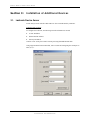
3.1. Lantronix Device Server
Traffic Analyst works with the UDS-10 Device Server manufactured by Lantronix.
Lantronix UDS-10 Setup
To configure the Lantronix, the following Network information is needed:
♦
A static IP address
♦
Subnet Mask IP Address
♦
Gateway IP Address
Connect via PC serial port to UDS-10 serial port using Standard Modem cable.
Using HyperTerminal or ProComm Plus, start a session and configuring the comm port to
9600, 8, N, 1.
JANUARY 2011
I M P AC T T E CH N O L OG I ES , I N C
CONFI DENTI AL AND PROPRI ETARY
59
T R AF F I C AN AL Y S T I N S T AL L A T I O N G UI D E
While powering on the UDS-10, hold down the “x” key on the keyboard until the UDS10 Menu appears.
♦
Hit [Enter] to get to the Change Setup menu.
♦
Hit 0 (zero) and [Enter].
♦
Enter the static IP address that you will be using.
♦
Answer “Y” to Set Gateway.
♦
Enter the gateway address the same way as the IP address.
♦
Netmask: You will need to enter the number of bits that match your network
configuration. Please refer to the IP Addressing section of the Lantronix
Installation Guide that came with the Lantronix Device to determine the correct
setting.
♦
“Change telnet config password” hit N and [Enter]
♦
When back at the Change Setup menu, select 9 and [Enter]. This will save your
settings and disconnect you from the UDS-10.
Connect the UDS-10 to the network via an Ethernet cable. Once connected, the “link”
light should be a steady green (which means that it is connected to the network) and the
“net Tx/Rx” flashing yellow (which shows network traffic).
If everything is configured correctly, connection via the IP Address should be available.
Go to Start…Run and type in “telnet xx.xx.xx.xx 9999” (where x represents the IP
address you assigned the UDS-10). The 9999 after the IP address will signify that we are
going in on the maintenance port.
If the port the Lantronix is connected to will be something other than 9600, 8, N, 1, then
the Channel 1 configuration will need to be changed. From the Main Menu, select option
1 and change the fields to correspond to the correct information.
The device is now ready to connect to the port of the PBX.
To use the Lantronix with Traffic Analyst software you will need to install the Comm
Port Redirector software.
Note:
The IP Port is the port number configured on the Lantronix. IP port number 10001 is the
default and is recommended. Only change the default port number if this has been
changed during the Lantronix setup. Check the option for a Lantronix password if one
has been configured. Then enter the password. See Lantronix Installation Guide for more
information.
3.2. Working with Buffer Boxes
Traffic Analyst works with the following buffer boxes. If you are using a buffer box that
is not on the list, contact Impact Technologies for assistance.
• Western Telematic's PollCat NetLink
• Western Telematic’s PollCat NetLink Jr (NLJ-512)
JANUARY 2011
I M P AC T T E CH N O L OG I ES , I N C
CONFI DENTI AL AND PROPRI ETARY
60
T R AF F I C AN AL Y S T I N S T AL L A T I O N G UI D E
• Scannex
Following is a discussion on setting up these boxes.
3.2.1. Western Telematic
3.2.1.1. PollCat NetLink – NetLink Jr
Traffic Analyst can poll data from Western Telematic's PollCat NetLink via TCP/IP or
modem. It does this once a day, usually just after midnight and before the next day starts.
The PollCat Netlink will accumulate all data for a day and provide it to Traffic Analyst
on request.
Before you start, make sure that you have a Ethernet connection, if polling via TCPIP,
available at the switch since the PollCat must be connected to your network once
configuration is complete. Or if not polling via TCPIP you will need a modem line to
connect to the PollCat.
Once you turn on the PollCat, you should see the Green light above “ON” and a flashing
amber light above “RDY”.
To setup PollCat for TCPIP:
Connect to PollCat via Modem (PollCat has built in internal 56K modem) or Direct
Connect from your PC serial port (comm port) to the Console Port (DCE). These port are
located on the back of the PollCat. You can use ProComm or HyperTerminal for this.
Default settings for Direct Connect are 9600 8, N, 1 and 57600, 8, N, 1 for Modem.
After 3 unsuccessful attempts at the PollCat password, the PollCat will disconnect you.
Once connected, hit [Enter] to get the Main Menu. If you get ERROR instead of the Main
Menu, it is looking for a password. By default, the password is SUPER and is casesensitive.
Once at the Main Menu, type in 22 (Port Configuration) and hit [Enter].
On the Port Configuration Menu, type in 6 (Network Port) and hit [Enter].
The following items need to be changed on the Network Port screen:
1. IP Address – This is a static IP address that your Networking or IT department must
assign.
2. Subnet Mask – This may or may not need to be changed. You will have to check with
your Networking or IT department.
3. Gateway Addr - This is a IP address that your Networking or IT department must
supply you with.
To change these items, select the appropriate number that corresponds to the item you
need to change.
Enter each address as needed and then hit [ESC] to return to the Port Configuration
Menu.
JANUARY 2011
I M P AC T T E CH N O L OG I ES , I N C
CONFI DENTI AL AND PROPRI ETARY
61
T R AF F I C AN AL Y S T I N S T AL L A T I O N G UI D E
This portion will need to be completed if polling with TCPIP or Modem:
Now select PBX Port A, PBX Port B or PBX Port AUX, whichever one that the Traffic
data will be coming in on, and hit [Enter]. For POLLCAT Jr. (NLJ-512), you will only
have a PBX Port A. Settings 1-4 for the PBX Port MUST match the settings to the port
you are going to be using on the PBX, otherwise the PollCat will not be able to
communicate with the switch.
Hit [ESC] until you are back at the Main Menu.
You need to SAVE the parameters to the PollCat otherwise if power is lost to it, the
changes made will be lost.
To save, type 7 (Save Parameters) and hit [Enter]. Answer Y at the “Sure?” prompt and
hit [Enter]. Hit [Enter] after it has saved to return to the Main Menu.
Back at the Main Menu, type 8 (Exit Command Mode) and hit [Enter]. You should get an
on-screen message of “Command Mode Exited”. At this point you can close your
terminal program (HyperTerminal, ProComm, etc…)
Since we have added the TCP/IP address to the PollCat, we need to test it to make sure
that we can communicate with it since Traffic Analyst will only use the TCP/IP
connection to communicate with the PollCat. Make sure you are testing it from the
computer that will have Traffic Analyst installed on it. You will need to use telnet, which
is a standard Windows program. Click on the Start button, then Run or get to a Command
Prompt (DOS prompt). Type in “telnet xx.xx.xx.xx” without the quotes and where “x” is
the IP address of the PollCat that you assigned to it. This should open a new window.
NOTE: If you get a message that says “Cannot connect to xx.xx.xx.xx”, then you either
have the wrong IP address or something is not configured correctly on the PollCat.
You should now see “POLLCAT-NETLINK” on the screen. This does require a
password to access it. By default it is SUPER and is case-sensitive. You will not see the
password as you type it. Make sure you hit [Enter] after you type in the password. You
should now get a READY message. Hit [Enter] to get to the Main Menu. You can now
make future changes using the telnet connection.
Once you have finished configuring the PollCat, you now need to connect it to your
switch. There is a cable supplied with the PollCat that has one end marked as “PBX” and
the other end as “POLLCAT”. There is also a connector that is marked as “Null
Connector” which you need to connect to the “PBX” end of the cable before plugging it
into your PBX.
Once you have plugged in all the cables, including the Ethernet connection, the PollCat
should be ready to accept data from the PBX. You will have to configure your switch to
export the data on the port we are connected to.
To assist in this set-up, here is how Traffic Analyst works with the PollCat NetLink:
1.
JANUARY 2011
Traffic Analyst will try to access the Command Mode of the PollCat through TCP/IP port
#23, using the Host Name or IP Address defined in its Switch Communications settings
or via a modem using the Modem number and baud/parity rate you set up. These settings
need to match what is setup in the PollCat.
I M P AC T T E CH N O L OG I ES , I N C
CONFI DENTI AL AND PROPRI ETARY
62
T R AF F I C AN AL Y S T I N S T AL L A T I O N G UI D E
2.
Traffic Analyst first looks for the prompt "PollCat-NetLink" and if it sees it, Traffic
Analyst sends the password defined in its Switch Communications settings and waits for
a "Ready" prompt to display. (Note: the password is case sensitive, so be careful that it is
entered into Traffic Analyst correctly.)
If Traffic Analyst does not see the "PollCat-Netlink" prompt, it looks for the "Ready" prompt
anyway, and proceeds if it finds it. It also looks for the "Enter Selection" prompt, meaning that the
PollCat menu has been enabled for a network connection, and if found, Traffic proceeds
appropriately. If none of these prompts appear within the timeout time, then Traffic Analyst stops
and logs a failure.
3.
Assuming Traffic Analyst has obtained Command Mode with the PollCat, it issues the
following command to retrieve the data: ^B01,STD,SP
Where SP is PA (port A), PB (port B) or PX (auxiliary), whichever port is used to collect
traffic data and defined in Traffic Analyst's Switch Communication settings. The STD
command segment requests standard (non-alarm) records.
4.
All data up to the END DATA message will be collected. Traffic will then issue this
command: ^B25,Y
This resets all records in the port's current memory partition.
5.
Last, Traffic issues the ^B09 command to exit the Command Mode and discontinue the
connection.
3.2.2. Omnitronix
3.2.2.1. Poll-Safe
Traffic Analyst can poll data from Omnitronix Poll-Safe buffer box PS680 or PS635 via a
modem. It does this once a day, usually just after midnight and before the next day starts.
The Poll-Safe will accumulate all data for a day and provide it to Traffic Analyst on
request.
The size of the buffer box should be able to hold enough records for a full day and maybe
two days if a problem happens when trying to dial into the buffer box. For sizing
recommendation, usually a 2MB unit is large enough but it is a good idea to connect
Impact Technologies if you have questions on which buffer box is right for you.
Please refer to your user manual to setup the buffer box to your switch.
To configure the buffer box you will need to connect to the buffer box using ProComm or
Windows HyperTerminal. You will see the Connect message soon but it may 10 seconds
or so before you see the Answer String of POLLSAFE PS680 or POLLSAFE PS635p.
At this point you should be able to enter commands and see responses from the Poll-Safe.
You will want to type a ^B (hold the Control key down and type a B).
Now you can type STATUS or a question mark (?). You should see a status display
transmitted. Next you will want to go through the SETUP. It is very important to setup
the date and time, the baud rate and parity setting of the input port. This is the port that
will be connected to the port of your PBX. These settings will need to match the port
settings of the PBX exactly. Compress will also need to set to OFF.
JANUARY 2011
I M P AC T T E CH N O L OG I ES , I N C
CONFI DENTI AL AND PROPRI ETARY
63
T R AF F I C AN AL Y S T I N S T AL L A T I O N G UI D E
Once you have finished configuring the Poll-Safe, you now need to connect it to your
switch. The Input port is Configured as DTE port, most PBX ports are configured as
DCE therefore most likely required configuration is a just a straight through cable. If the
PBX port is also DTE you will need a NULL modem adapter also.
Connect the serial cable to the Poll-Safe Input port. When this connection is properly
made, the RXD IN LED should turn GREEN. If the RXD IN LED is RED then
something is not correct and you should try a different cable. If it is neither RED nor
GREEN, then insert the null modem adapter between the Poll-Safe and the cable from the
PBX or you can change the jumpers to the Poll-Safe to be DCE. You will need to
reference your user’s manual for information.
The RDX IN LED will be GREEN and will flicker RED when data is being transmitted
from the PBX.
Since the Poll-Safe PS680 can understand PollCat commands Traffic Analyst will use
those commands for the Poll-Safe. The Poll-Safe PS635 does not understand the PollCat
command so the Poll-Safe commands are used to access the data and clear the buffer
after data collection has occurred.
3.2.3. Scannex
Traffic Analyst can poll data from the Scannex once an hour (or more frequently if
needed).
When you set up Traffic Analyst for use with the Scannex, you will need to enter a user
name and password that the Scannex will recognize. You will also need to enter the
filename of the file Traffic Analyst will retrieve. Consult your Scannex documentation
for this information.
There is a utility available from the Scannex website, SE Discoverer, that you can use to
help you with the Scannex set up. As of this writing, the URL for downloading this
Scannex utility is as follows:
SE Discover program - http://www.scannex.com/tools/setup_sediscover.exe
Please note that this URL can change at any time, so you may have to go to scannex.com
to search for it.
You can also download the IP User Manual at:
http://www.scannex.com/docs/ipbuffer_manual_20080502.pdf
Again, this URL is subject to change.
3.2.3.1. Setting up the Scannex ip.buffer
Assuming you are connecting it to the LAN (with a direct connect serial cable to the
PBX), connect the ip.buffer to your LAN (and the serial cable to the PBX) and connect to
power outlet.
1.
JANUARY 2011
Open up SE Discover program.
I M P AC T T E CH N O L OG I ES , I N C
CONFI DENTI AL AND PROPRI ETARY
64
T R AF F I C AN AL Y S T I N S T AL L A T I O N G UI D E
JANUARY 2011
2.
Click on the Spyglass icon. The ip.buffer should now be seen in the box below.
Single click the buffer and then click the World symbol.
3.
This should now take you to the web browser page of the ip.buffer. Click on the Setup tab and enter the Username (admin) and Password (secret).
4.
Click on Global Settings.
I M P AC T T E CH N O L OG I ES , I N C
CONFI DENTI AL AND PROPRI ETARY
65
T R AF F I C AN AL Y S T I N S T AL L A T I O N G UI D E
JANUARY 2011
5.
Now click on Network (Network & System) settings …………show tab.
6.
Change the fields to match your chosen IP address Subnet & Gateway, and then go
to the bottom of the page and click Save.
7.
Click on Global Date & Time and check to be sure that the time is correct. Click on
Save when satisfied.
8.
Click on Channels ….Channel 1.
I M P AC T T E CH N O L OG I ES , I N C
CONFI DENTI AL AND PROPRI ETARY
66
T R AF F I C AN AL Y S T I N S T AL L A T I O N G UI D E
9.
In Source, the default should be Com 1 Serial, which is correct.
10. In Destination, select the correct output, FTP Server. Then click the Show tab to
adjust the settings to your requirements.
11. In the Autodelete field, make sure that Delete After Download is selected.
12. Note the Username, Password, and Filename in the FTP Server section. This
information needs to be entered in the Traffic Analyst Communication tab for this
switch. It’s the information that Traffic Analyst will use to access the buffer box.
The file name is the name of the file containing the CDR data that Traffic Analyst
will retrieve.
13. When you are finished, click on Save. Your buffer box should be set up properly
now. You may now close the Scannex ip buffer web-browser page.
JANUARY 2011
I M P AC T T E CH N O L OG I ES , I N C
CONFI DENTI AL AND PROPRI ETARY
67
T R AF F I C AN AL Y S T I N S T AL L A T I O N G UI D E
Section 4:
Appendix
4.1. Configuring IIS with ARR (Windows 7, 2008, Vista)
Follow the steps below to ensure that TrafficWeb is properly configured for using IIS to
send Web requests to and from the TrafficWeb application via Tomcat services.
NOTE: If not already on the server, IIS must be installed first, before installing ARR. To
check if IIS is installed, open Administrative Tools from the Control Panel and then open
the IIS Manager. If you are unable to open IIS, it probably is not installed.
First, download and install ARR version 2.0 or later. To find an available download, enter
“Microsoft Application Request Routing” into your favorite search engine. Once this is
downloaded, run the installer. (Note: The ARR installer displays a dialog near the end of
the install - which mentions the location of the log file. Make sure you examine this log
file. The installer does not alert the user of all install errors; therefore, you must manually
read this log file before assuming the installer worked.)
Follow these instructions when using Web Platform Installer to install ARR.
Select the Web Platform tab. Then, under Web Server, select Customize.
Next, select the Application Request Routing option, located under the Common HTTP
Features heading.
JANUARY 2011
I M P AC T T E CH N O L OG I ES , I N C
CONFI DENTI AL AND PROPRI ETARY
68
T R AF F I C AN AL Y S T I N S T AL L A T I O N G UI D E
Click the Install button. Another window will appear. Click “I Accept” to agree to
Microsoft license terms. Note: You may be prompted to reboot your computer after the
installation is complete. If so, reboot your computer and continue with configuration.
When ARR is finished installing, a window will appear informing you that the install was
successful. Select Finish to close this window.
JANUARY 2011
I M P AC T T E CH N O L OG I ES , I N C
CONFI DENTI AL AND PROPRI ETARY
69
T R AF F I C AN AL Y S T I N S T AL L A T I O N G UI D E
After ARR is successfully installed, open the IIS Manager. You are going to configure
IIS with a new ARR “Rewrite URL” rule.
To configure IIS and ARR, click on the main IIS entry in the IIS Manager tree. You
should see an “Application Request Routing” option. Select this option to open ARR.
The following screen appears. Select Server Proxy Settings from the sidebar on the right
to go on to the next step.
A new screen, labeled Application Request Routing, will appear. A sample configuration
for this screen with recommended settings is provided on the next page.
It is important that the following fields are filled out accordingly:
• Enable proxy – checked
• HTTP Version – Pass through
• Keep alive – checked
• Time-out – enter an amount of time; 120 seconds recommended
• Reverse rewrite host in response headers – checked
• Preserve client IP in the following header – X-Forwarded-For
The remaining fields may either be left as the default or changed as needed.
JANUARY 2011
I M P AC T T E CH N O L OG I ES , I N C
CONFI DENTI AL AND PROPRI ETARY
70
T R AF F I C AN AL Y S T I N S T AL L A T I O N G UI D E
Scroll down to see the rest of the fields on this screen.
Once this is configured, click Apply (located on the right sidebar in the Application
Request Routing screen) to save your changes. Then, click on the URL Rewrite…
option, also located in the right sidebar.
The URL Rewrite screen will appear. Select Add Rule(s)… from the right sidebar.
JANUARY 2011
I M P AC T T E CH N O L OG I ES , I N C
CONFI DENTI AL AND PROPRI ETARY
71
T R AF F I C AN AL Y S T I N S T AL L A T I O N G UI D E
An Add Rule(s) dialog box will appear. Under Inbound Rules, select Blank Rule and
click OK.
You are now on the Edit Inbound Rule screen. Designate a name (e.g. TomcatProxy) for
this rule in the Name field and make sure these fields are filled out as follows:
• Requested URL – Matches the pattern
• Using – Wildcards
• Pattern – trafficweb*
• Ignore case – checked
• Action type – Rewrite
• Rewrite URL – http://127.0.0.1:8080/trafficweb/{R:1}
• Append query string – checked
• Stop processing of subsequent rules – unchecked
JANUARY 2011
I M P AC T T E CH N O L OG I ES , I N C
CONFI DENTI AL AND PROPRI ETARY
72
T R AF F I C AN AL Y S T I N S T AL L A T I O N G UI D E
Be sure to click Apply (in the right sidebar) to save your changes.
JANUARY 2011
I M P AC T T E CH N O L OG I ES , I N C
CONFI DENTI AL AND PROPRI ETARY
73