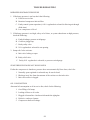
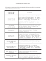
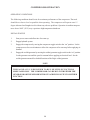
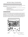
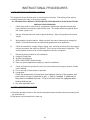
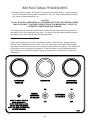
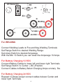
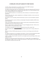
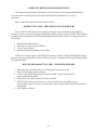
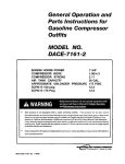
1
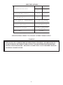
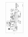
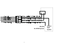
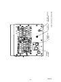
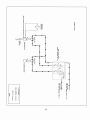
FABCO POWER
845-469-9151
Fax: 845-469-7871
PO BOX 582
CHESTER NY 10918
WWW.FABCOPOWER.COM
Email: [email protected]
EAGLE 6 IN 1 POWER STATION
OPERATORS, MAINTENANCE
AND PARTS MANUAL
P/N: 308276
03/24/2010 CRH
Mfg. of: Vehicle Mounted Generators
Hydraulic Generator Systems
Hydraulic Welders
2
CAUTION
If this System is used in less then 1 ½ Hour
operations
You must change the Air end Hydr.Oil every 30
Days.
Using this System in short periods less than 1
Hour will
create moister in the Hydraulic Oil and will
damage the Air End beyond repair.
By changing the Oil every 30 Days this damage
will be avoided.
Damage to the Air End is NOT covered under
the Warranty.
3
OPERATORS, MAINTENANCE, AND PARTS MANUAL
EAGLE 6 IN 1
Operation & Maintenance Section
TABLE OF CONTENTS
Operation & Maintenance Section
Specifications ...................................................................................................................... 6
Safety .................................................................................................................................. 7
Compressor Terminology .................................................................................................. 11
Description of Components............................................................................................... 12
Inspection, Lubrication, and Maintenance.......................................................................... 15
Troubleshooting ................................................................................................................. 23
Compressor Operation ...................................................................................................... 26
Parts and Illustration Section............................................................................................. 28
Recommended Spare Parts ................................................................................................ 40
Instructional Procedures for Installation ........................................................................... 41
Warranty Section
Warranty Information ........................................................................................................ 46
4
308276
SPECIFICATIONS
CFM
30
PSI
110
GENERATOR MAX OUTPUT
V OLTS
120/240
WELD ER MAX OUTPUT
AMPS
300
C OM P RE S S OR D E L IV E RY
F L UID C A PA C ITY - C OM P RE S S OR
( N O T H YD R A U L IC )
2 . 0 G A L L O N S YS TE M
.75 COMPRESSOR SUMP
H YD R A U L IC D E L IV E R Y
25 GPM @2000 PSI
C O M P O N E N TS S YS TE M
OV E RA L L D IM E NS IONS
(SEE BELOW)
W E IGHT ( W E T)
475LBS.
SPECIFICATIONS SUBJECT T O CHANGE WITHOUT PRIOR NOTICE
WARNING
THE EAGLE 6 IN 1 IS DESIGNED FOR OPERATIONS UTILIZING A GEARED PUMP. IFA
LOAD SENSING PUMP IS BEING USED, CONTACT YOUR DISTRIBUTOR FOR PROPER
INSTALLATION PROCEDURE. FAILURE TO COMPLY WILL CAUSE PROPERTY DAMAGE
OR SERIOUS BODILY INJURY.
5
SAFETY
WARNING
ALL UNITS ARE SHIPPED WITH A DETAILED OPERATORS AND PARTS
MANUAL. THIS MANUAL CONTAINS VITAL INFORMATION FOR THE SAFE
USE AND EFFICIENT OPERATION OF THIS UNIT. CAREFULLY READ
THE OPERATORS MANUAL BEFORE STARTING THE UNIT. FAILURE TO
ADHERE TO THE INSTRUCTIONS COULD RESUL T IN SERIOUS BODILY
INJURY OR PROPERTY DAMAGE.
AIR COMPRESSOR SAFETY PRECAUTIONS
Safety is basically common sense. While there are standard safety rules, each situation has its own
peculiarities that cannot always be covered by rules. Therefore with your experience and common
sense, you are in a position to ensure your safety
. Lack of attention to safety can result in:
accidents, personal injury, reduction of efficiency and worst of all - Loss of Life.Watch for safety
hazards. Correct them promptly. Use the following safety precautions as a general guide to safe
operation:
Do not attempt to remove any compressor parts without first relieving the entire system of
pressure.
Do not attempt to service any part while machine is operating.
DANGER
CHECK THE COMPRESSOR SUMPOIL LEVEL ONLY WHEN THE COMPRESSOR
IS NOT OPERATING AND SYSTEM IS COMPLETELY RELIEVED OF PRESSURE.
OPEN SERVICE VALVE TO ENSURE RELIEF OF SYSTEMAIR PRESSURE WHEN
PERFORMING MAINTENANCE ON COMPRESSORAIR/OIL SYSTEM. FAILURE
TO COMPLY WITH THIS WARNING MAY CAUSE DAMAGE TO PROPERTY
AND SERIOUS BODILY HARM.
Do not operate the compressor at pressure(s) or speed in excess of its rating as indicated in
“Compressor Specifications”.
Periodically check all safety devices for proper operation.
Do not play with compressed air. Pressurized air can cause serious injury to personnel.
Exercise cleanliness during maintenance and when making repairs by covering parts and exposed
openings.
6
SAFETY
DANGER
DO NOT USE FABCOs COMPRESSOR SYSTEMS TO PROVIDE
BREATHING AIR. SUCH USAGE,WHETHER SUPPLIED IMMEDIATELY FROM
THE COMPRESSOR SOURCE, OR SUPPLIED TO BREATHING TANKS FOR
SUBSEQUENT USE, CAN CAUSE SERIOUS BODILY INJURY.
BOSS INDUSTRIES, INC. DISCLAIMSANY AND ALL LIABILITIES FOR DAMAGE
FOR LOSS DUE T O PERSONAL INJURIES, INCLUDING DEATH, AND/OR
PROPERTY DAMAGE INCLUDING CONSEQUENTIAL DAMAGES ARISING OUT
OF ANY BOSS INDUSTRIES, INC. COMPRESSORS USED TO SUPPLY BREATHING
AIR.
Do not disconnect or bypass safety circuit system.
Do not install safety devices other than authorized BOSS INDUSTRIES, INC. replacement
devices.
Close all openings and replace all covers and guards before operating compressor unit.
Tools, rags, or loose parts must not be left on the compressor or drive parts.
Do not use flammable solvents for cleaning parts. This can cause the unit to ignite during operation.
Keep combustibles out of and away from the Compressor/Inlet and any associated enclosures.
The owner, lessor, or operator of the Compressor are hereby notified and forewarned that any
failure to observe these safety precautions may result in damage or injury
.
FABCO POWER expressly disclaims responsibility or liability for any injury or damage
caused by failure to observe these specified precautions or by failure to exercise that ordinary
caution and due care required when operating or handling the Compressor
, even though not
expressly specified above.
7
SAFETY
A compliment of warning decals is supplied with each unit. These decals must be affixed to the
comressor package in the locations noted in this manual. If for any reason a safety decal is
removed it is the owners responsibility to make sure it is replaced.
8
SAFETY
9
COMPRESSOR TERMINOLOGY
AIR/OIL COALESCER - Performs second stage separation of oil from compressed air feeding
air tools. Sometimes referred to as the separator element.
CFM - Refers to the volume of compressed air being produced, expressed as cubic feet of air per
minute.
COMPRESSOR LUBRICANT - DEXRON IIIATF.
GPM - Refers to the amount of gallons per minute of hydraulic fluid flowing through the pump
.
OIL SUMP - The first stage of oil separation from compressed air
. Also serves as reservoir area
for compressor lubricant and sometimes referred to as the receiver tank.
PSI - Refers to the operating pressure the system is set up at, expressed as pounds per square
inch.
SAFETY VALVE - A valve located on the oil sump which opens in case of excessive pressure.
Sometimes referred to as the pop-off or pressure relief valve.
10
DESCRIPTION OF COMPONENTS
COMPRESSOR ASSEMBLY
The FABCO hydraulic drive compressor assembly is a positive displacement, oil
flooded, rotary screw type unit employing one stage of compression to achieve the desired
pressure. Components include a housing (stator), two screws (rotors), bearings, and bearing
supports. Power from the hydraulic motor shaft is transferred to the male rotor through a drive
coupling. The female rotor is driven by the male rotor
. There are five lobes on the male rotor
while the female rotor has six roots.
PRINCIPLES OF OPERATION
In operation, two helical grooved rotors mesh to compress air
. Inlet air is trapped as the male
lobes roll down the female grooves, pushing trapped air along, compressing it until it reaches the
discharge port in the end of the stator and delivers smooth-flowing, pulse-free air to the receiver
.
During the compression cycle, oil is injected into the compressor and serves these purposes:
1. Lubricates the rotating parts and bearings.
2. Serves as a cooling agent for the compressed air
.
3. Seals the running clearances.
LUBRICATION SYSTEM
Oil from the compressor at discharge pressure, is directed into its integral housing, through the
thermal valve and filter, and then out of the integral housing to the oil cooling system, and then back
to the side of the compressor stator, where it is injected into the compressor. At the same time oil
is directed internally to the bearings and shaft seal of the compressor
.
OIL SUMP
Compressed, oil-laden air enters the sump from the compressor
. As the oil-laden air enters the
sump, most of the oil is separated from the air as it passes through a series of baffles and diffusion
plates. The oil accumulates at the bottom of the sump for recirculation. However
, some small
droplets of oil remain suspended in the air and are passed on to the Coalescer
.
11
DESCRIPTION OF COMPONENTS
SAFETY VALVE
The pop safety valve is set at 200 PSI and is located at the top of the air/oil sump. This valve acts
as a backup to protect the system from excessive pressure that might result from a malfunction.
AIR/OIL COALESCER
The coalescer is self-contained within a spin-on housing. When air is demanded at the service line,
it passes through the coalescer which efficiently provides the final stage of oil separation.
OIL RETURN LINE
The oil that is removed by the coalescer accumulates and is returned through an internal oil return
line leading to the compressor.
MINIMUM PRESSURE VALVE
The minimum pressure valve is located at the outlet of the coalescer head and serves to maintain a
minimum discharge pressure of 75 PSIG in operation, which is required to assure adequate
compressor lubrication pressure.
OIL FILTER
The compressor oil filter is a removable and cleanable screen built into the side of the compressor
housing. Screen replacement may be necessary after several cleanings.
COMPRESSOR OIL
Compressor oil temperature is controlled by a thermal valve located down stream of the oil filter
.
The thermal valve maintains the compressor oil temperature at 185ºF
. Cool air is drawn through
the vented end panel and across the cooler.The air is heated by the cooler and the hot air exits out
the end vented panel . Allow for adequate clearance (12”) for the air to exit.Also, the package
location should not be subjected to above ambient air temperatures.
12
DESCRIPTION OF COMPONENTS
INSTRUMENTATION
The FABCO hydraulic drive compressor unit incorporates a gauge panel that monitors
temperature, pressure and hours of operation.
HOURMETER
The hourmeter records the total number of operating hours. It serves as a guide in following the
recommended inspection and maintenance schedule. The hourmeter will only run when there is pressure
in the system.
COMPRESSOR DISCHARGEAIR/OIL TEMPERATURE SWITCHGAUGE
This switchgauge indicates compressor air discharge temperature. The switchgauge ensures safety
shutdown in case of excessive operating temperatures, preventing compressor damage, by stopping
hydraulic flow to the compressor motor.
ELECTRICAL AND SAFETY SYSTEM
The FABCO compressor’s standard electrical system consists of:
-Gauge panel with a temperature switchgauge, hourmeter and discharge pressure switchgauge.
-Compressor and oil cooler fan assembly and relay
.
-3-way pressure switch and relay to control hourmeter and blowdown.
-(2) 12VDC N.O. hydraulic solenoid and relay.
CONTROL SYSTEM
The prime component of the compressor control system is the compressor inlet valve. The control
system is designed to match air supply to air demand and to prevent excessive discharge pressure
when compressor is at idle. Control of air delivery is accomplished by the inlet valve regulation
and modulation as directed by the discharge pressure regulator.
INLET VALVE
The compressor inlet valve is a piston operated disc valve that regulates the inlet opening to control
capacity and serves as a check valve at shutdown.
13
INSPECTION, LUBRICATION, AND MAINTENANCE
This section contains instructions for performing the inspection, lubrication, and maintenance
procedures required to maintain the compressor in proper operating condition. The importance of
performing the maintenance described herein cannot be over emphasized.
The periodic maintenance procedures to be performed on the equipment covered by this manual
are listed below. It should be understood that the intervals between inspections specified are
maximum interval. More frequent inspections should be made if the unit is operating in a dusty
environment, in high ambient temperature, or in other unusual conditions.A planned program of
periodic inspection and maintenance will help avoid premature failure and costly repairs. Daily
visual inspections should become a routine.
The LUBRICATION AND MAINTENANCE CHART lists serviceable items on this compressor
package. The items are listed according to their frequency of maintenance, followed by those
items which need only “As Required” maintenance.
The maintenance time intervals are expressed in hours. The hourmeter shows the
total number of hours your compressor has run. Use the hourmeter readings for determining your
maintenance schedules. Perform the maintenance at multiple intervals of the hours shown. For
example, when the hourmeter shows “100” on the dial, all items listed under “EVERY 10 HOURS”
should be serviced for the tenth time, and all items under “EVERY 50 HOURS” should be
serviced for the second time, and so on.
DANGER
COMPRESSOR MUST BE SHUT DOWN AND COMPLETELY RELIEVED OF
PRESSURE PRIOR TO CHECKING FLUID LEVELS. OPEN SERVICE VALVE TO
ENSURE RELIEF OF SYSTEMAIR PRESSURE. FAILURE TO COMPLY WITH THIS
WARNING MAY CAUSE DAMAGETO PROPERTY AND SERIOUS BODILY HARM.
14
LUBRICATION AND MAINTENANCE CHAR T
INTERVAL
ACTION
PERIODICALLY
DURING
OPERATION
1. Observe all gauge readings. Note any change
from the normal readings and determine the
cause. Have necessary repairs made. (NOTE:
"NORMAL" is the usual gauge reading when
operating at similar conditions on a day to day
basis.)
DAILY
1.
2.
3.
4.
EVERY 25 HOURS
OR MONTHLY
1. Drain water from compressor oil.
EVERY 500
HOURS OR 6
MONTHS
1. Change compressor oil and replace screen
2. Check compressor shaft seal for leakage.
3. Check air filter piping, fittings and clamps.
4. Check compressor supports.
5. Install new air filter element. (Shorter
interval may be necessary under dusty
conditions.)
6. Check sump safety valve.
EVERY 1000
HOURS OR 1
YE A R
1. Change coalescing element.
PERIODICALLY OR
AS REQUIRED
1. Inspect
2. Inspect
element if
3. Inspect
Check
Check
Check
Check
the compressor oil level.
air filter.
for oil and air leaks.
safety circuit switches.
and clean air filter element.
and replace spin-on coalescer
ne c e s s a ry.
and clean oil cooler fins.
NOTE: Compressor oil and filter is to be changed after the first 50 hours of operation After
.
this,
normal intervals are to be followed.
15
LUBRICANT RECOMMENDATIONS
WARNING
IT IS IMPORTANT THAT THE COMPRESSOR OIL BE OF A RECOMMENDED
TYPE AND THAT THIS OIL AS WELL AS THE AIR FILTER, OIL FILTER, AND
COALESCER ELEMENTS BE INSPECTED AND REPLACED AS STATED IN THIS
MANUAL.
THE COMBINATION OF A COALESCER ELEMENT LOADED WITH DIRT AND
OXIDIZED OIL PRODUCTS TOGETHER WITH INCREASED AIR VELOCITYAS A
RESULT OF THIS CLOGGED CONDITION MAY PRODUCE A CRITICAL POINT
WHILE THE MACHINE IS IN OPERATION WHERE IGNITION CAN TAKE PLACE
AND COULD CAUSE A FIRE IN THE OIL SUMP.
FAILURE T O COMPLY WITH THIS W ARNING MAY CAUSE DAMAGE T O
PROPERTY AND SERIOUS BODILY HARM.
The following are general characteristics for a rotary screw lubricant. Due to the impossibility of
establishing limits on all physical and chemical properties of lubricants which can affect their
performance in the compressor over a broad range of environmental influences, the responsibility
for recommending and consistently furnishing a suitable heavy duty lubricant must rest with the
individual supplier if they choose not to use the recommended BOSS INDUSTRIES rotary screw
lubricant. The lubricant supplier’s recommendation must, therefore, be based upon not only the
following general characteristics, but also upon his own knowledge of the suitability of the
recommended lubricant in helical screw type air compressors operating in the particular
environment involved.
CAUTION
MIXING DIFFERENT TYPES OR BRANDS OF LUBRICANTS IS NOT
RECOMMENDED DUE TO THE POSSIBILITY OF A DILUTION OF THE
ADDITIVES OR A REACTION BETWEENADDITIVES OF DIFFERENT TYPES.
16
LUBRICANT RECOMMENDATIONS
LUBRICANT CHARACTERISTICS
1.
2.
3.
4.
5.
Flash point 400°F minimum.
Pour point -40°F.
Contains rust and corrosion inhibitors.
Contains foam suppressors.
Contains oxidation stabilizer.
NOTE
DUE TO ENVIRONMENTAL FACTORS THE USEFUL LIFE OFALL “EXTENDED
LIFE” LUBRICANTS MAY BE SHORTER THAN QUOTED BYTHE LUBRICANT
SUPPLIER. BOSS INDUSTRIES, INC. ENCOURAGES THE USER TO CLOSELY
MONITOR THE LUBRICANT CONDITION AND TO PARTICIPATE IN AN OIL
ANALYSIS PROGRAM WITH THE SUPPLIER.
NOTE
NO LUBRICANT, HOWEVER GOOD AND/OR EXPENSIVE, CAN REPLACE
PROPER MAINTENANCE AND ATTENTION. SELECTAND USE IT WISELY.
17
MAINTENANCE
If some of the maintenance intervals in the schedule outlined in this manual seem to be rather short,
it should be considered that one hour’s operation of a compressor is equal to about 40 road miles
on an engine. Thus, eight hours operation is equal to 320 road miles, 250 hours is equal to 10,000
road miles, etc.
COMPRESSOR OIL SUMP FILL, LEVEL,AND DRAIN
Before adding or changing compressor oil make sure that the compressor is completely relieved of
pressure. Oil is added at the fill cap on the side of the compressor body. A drain valve/hose
assembly is provided at the bottom of the compressor body
. The proper oil level is between the
top and the midpoint of the oil sightglass, when the unit is shut down and has had time to settle.
The truck must be level when checking the oil. DO NOT OVERFILL. The oil sump capacity is
given in “Compressor Specifications”.
DANGER
DO NOT ATTEMPT TO DRAIN CONDENSATE, REMOVE THE OIL LEVEL FILL
PLUG, OR BREAK ANY CONNECTION IN THE AIR OR OIL SYSTEM WITHOUT
SHUTTING OFF COMPRESSOR AND MANUALLY RELIEVING PRESSURE FROM
THE SUMP. FAILURE TO COMPLY WITH THIS WARNING MAY CAUSE DAMAGE
TO PROPERTY AND SERIOUS BODILY HARM.
AIR INTAKE FILTER
The air intake filter is a heavy-duty dry type high efficiency filter designed to protect the
compressor from dust and foreign objects. Optional two-stage available.
Optional filter is equipped with an evacuator cup for continuous dust ejection while operating and
when stopped.
Frequency of maintenance of the filter depends on dust conditions at the operating site. The filter
element must be serviced when clogged (maximum pressure drop for proper operation is 15” of
water). The filter is equipped with a pressure drop indicator
, and the element should be changed
based on its reading first and then by the maintenance intervals outlined.
18
MAINTENANCE
AIR/OIL COALESCER
The air/oil coalescer employs an element permanently housed within a spin-on canister
. This is a
single piece unit that requires replacement when it fails to remove the oil from the discharge air, or
pressure drop across it exceeds 15 PSI. Dirty oil clogs the element and increases the pressure
drop across it.
To replace element proceed as follows:
1.
2.
3.
4.
Shutdown compressor and wait for complete blow down (zero pressure).
Turn element counterclockwise for removal (viewing element from bottom).
Apply a film of fluid directly to seal on the new element.
Rotate element clockwise by hand until element contacts seal (viewing element from
bottom).
5. Rotate element approximately one more turn clockwise with band wrench near the top
of element.
6. Run system and check for leaks.
WARNING
DO NOT SUBSTITUTE ELEMENT. USE ONLY A GENUINE BOSS INDUSTRIES
REPLACEMENT ELEMENT. THIS ELEMENT IS RATED AT 200 PSI WORKING
PRESSURE. USE OFANY OTHER ELEMENT MAY BE HAZARDOUS AND COULD
IMPAIR THE PERFORMANCE AND RELIABILITY OF THE COMPRESSOR,
POSSIBLY VOIDING THE WARRANTY AND/OR RESULTING IN DAMAGE TO
PROPERTY AND SERIOUS BODILY HARM.
COALESCER OIL RETURN
This originates at the bottom of the air/oil coalescer and flows through a special recovery pipe and
venturi nozzle. If the coalescer starts to fill with oil there is a good chance the venturi or pipe has
been plugged. Consult factory for cleaning instructions.
19
MAINTENANCE
OIL FILTER
The compressor oil filter is a throwaway type cartridge. It is designed with a built-in bypass so that
if there is a large restriction, due to cold oil or clogged element, the compressor will still be
lubricated.
To replace filter proceed as follows:
1. Make sure system pressure is relieved.
2. Unscrew with 14mm allen wrench.
3. Remove oil filter from housing.
4. Replace the oil filter screen element.
5. Reinsert oil filter screen into housing and tighten with 14mm allen wrench.
6. Add oil (total system takes one gallon), re-tighten filler cap.
7. Check for leaks in operation.
WARNING
DO NOT SUBSTITUTE ELEMENT. USE ONLY A GENUINE BOSS INDUSTRIES
REPLACEMENT ELEMENT . USE OF ANY OTHER ELEMENT MA Y BE
HAZARDOUS AND COULD IMPAIR THE PERFORMANCE AND RELIABILITY
OF THE COMPRESSOR, POSSIBL Y VOIDING THE WARRANTY AND/OR
RESULTING IN DAMAGE TO PROPERTY AND SERIOUS BODILY HARM.
COMPRESSOR OIL COOLER
The interior of the oil cooler should be cleaned when the pressure drop across it at full flow
exceeds 25 PSI. The following procedure has been recommended by the vendor who supplies the
cooler:
1.
2.
3.
4.
Remove cooler.
Circulate a suitable solvent to dissolve and remove varnish and sludge.
Flush generously with compressor lubricant
Once the coolers are reinstalled, fill the compressor with the proper fluid to
appropriate level.
20
MAINTENANCE
SHAFT SEAL
SHAFT SEAL INSTALLATION INSTRUCTIONS:
1. Remove hydraulic motor, drive coupling and adapter housing from face of compressor
.
2. Remove coupling hub from compressor shaft.
3. Remove 4 screws from shaft seal cover and press seal out.
4. Pull seal wear sleeve off shaft with puller.
5. Clean shaft surface removing all burrs from shaft where the wear sleeve gets installed.
6. Press new wear sleeve on to shaft. Oil heating new wear sleeve to 212°F approximately
aids in the installation of this ring.
7. Press new seal into housing with seal assembly tool, until contact with snapring.
8. Temporarily install new seal installation cone over shaft to protect seal during reinstallation.
9. Reinstall cover.
10. Reinstall coupling hub to compressor shaft.
11. Reinstall adapter housing, drive coupling, and hydraulic motor to face of compressor
.
21
TROUBLESHOOTING
This section contains instructions for troubleshooting the equipment following a malfunction.
The troubleshooting procedures to be performed on the equipment are listed below
. Each
symptom of trouble for a component or system is followed by a list of probable causes of the
trouble and suggested procedures to be followed to identify the cause.
In general, the procedures listed should be performed in the order in which they are listed, although
the order may be varied if the need is indicated by conditions under which the trouble occurred. In
any event, the procedures which can be performed in the least amount of time and with the least
amount of removal or disassembly of parts, should be performed first.
UNPLANNED SHUTDOWN
When the operation of the machine has been interrupted by an unexplained shutdown, check the
following:
1. Check the fuel level and truck dash gauges and indications for possible engine
problems.
2. Check the compressor discharge temperature/switchgauge. If the latching relay circuit
is tripped the 12VDC solenoid will lose power and divert hydraulic oil back to the
reservoir. The compressor blowdown pressure switch and the temperature switchgauge
will not allow power to the hydraulic solenoid until the air has blown down and the
temperature has dropped into its normal operating range and the push button has been
reset. Take compressor in for service once a high temperature shutdown has occurred.
Failure to do so will void your warranty.
3. Check that the compressor oil is at proper level.
4. Check oil cooler for dirt, slush, ice on the fins, or any other obstructions to the cooling
air flow.
5. Make a thorough external check for any cause of shutdown such as broken hose,
broken oil lines, loose or broken wire, etc.
22
TROUBLESHOOTING
IMPROPER DISCHARGE PRESSURE
1. If discharge pressure is too low, check the following:
A. Leaks in service line.
B. Restricted compressor inlet air filter.
C. Faulty control system operation (i.e.N.0. regulated air solenoid is allowing air through
all the time.)
D. Low compressor oil level.
2. If discharge pressure is too high, safety valve blows, or system shuts down on high pressure,
check the following:
A. Faulty discharge pressure switchgauge.
B. Coalescer plugged up.
C. Faulty safety valve.
D. N.O. regulated air solenoid is not opening.
3. Sump relief valve activates:
A. Inlet valve leaking or open.
B. Faulty relief valve.
C. Faulty N.O. regulated air solenoid, or pressure switchgauge.
SUMP PRESSURE DOES NOT BLOW DOWN
If after the compressor is shutdown, pressure does not automatically blow down, check for:
1. Normally open regulated air solenoid may be stuck closed.
2. Blockage in air line from downstream of the coalescer to the inlet valve.
3. Inlet valve orifice is clogged.
OIL CONSUMPTION
Abnormal oil consumption or oil in service line, check for the following:
1.
2.
3.
4.
5.
Over filling of oil sump.
Leaking oil lines or oil cooler.
Plugged oil return line: check nozzle beneath the sightglass.
Defective coalescer element.
Compressor shaft seal leakage.
23
TROUBLESHOOTING
COALESCER PLUGGING
If the coalescer element has to be replaced frequently because it is plugging up, it is an indication
that foreign material may be entering the compressor inlet or the compressor oil is breaking down.
Compressor oil can break down prematurely for a number or reasons.
(1) Extreme operating temperature, (2) negligence in draining condensate from oil sump, (3) using
the improper type of oil, (4) dirty oil, (5) oil return nozzle plugged.
The complete air inlet system should be checked for leaks.
HIGH COMPRESSOR DISCHARGE TEMPERATURE
1.
2.
3.
4.
5.
Check compressor oil level. Add oil if required (see Section for oil specifications).
Check thermal valve operation.
Clean outside of oil cooler.
Clean oil system (cooler) internally.
Check fan relay harness.
24
COMPRESSOR OPERATION
Before starting the compressor, read this section thoroughly. Familiarize yourself with the controls and
indicators, their purpose, location, and use.
CONTROL OR
IN D IC ATOR
PURPOSE
TEMPERATURE
SWITCHGAUGE
Monitors the temperature of the air/fluid
mixture leaving the compressor. The normal
reading should be approximately 175 to 210
degrees F. S ends si gnal to relay when the
compressor reaches 240 degrees
temperature and the compressor will shut
down.
PRESSURE
SWITCHGAUGE
Monitors the pressure inside the sump tank.
When the pressure reaches 165 PSI the
compressor will shut down
HOURMETER
Indicator accumulated hours of actual
compressor operation.
FLUID LEVEL
SIGHTGLASS
Indicates fluid level in the sump. Proper
level should be between midpoint and top of
the sightglass. Check this level when the
compressor is disengaged and the vehicle is
parked on level ground.
PRESSURE RELIEF
VALVE
Vents sump pressure to the atmosphere if
the pressure inside the sump exceeds 175
PSI.
COMPRESSOR INLET
CONTROL VALVE
Regulates the amount of air intake in
accordance with the amount of compressed
air being used. Isolates fluid in compressor
unit on shutdown.
N.O. REGULATED AIR
SOLENOID
Sends air pressure to intake valve for
automatic regulation.
MINIMUM PRESSURE
VALVE
Restricts air flow to balance sump and
service air pressure. Assures a minimum of
65 PSI to maintain compressor lubrication.
25
COMPRESSOR OPERATION
OPERATING CONDITIONS
The following conditions should exist for maximum performance of the compressor
. . The truck
should be as close to level as possible when operating. The compressor will operate on a 15
degree sideward and lengthwise tilt without any adverse problems. Operation in ambient temperatures above 100°F (38°C) may experience high temperature shutdown.
INITIAL START-UP
1.
2.
3.
4.
Start power source and allow time for warm-up.
Engage hydraulic system.
Engage the compressor by moving the compressor toggle switch to the “on” position. Let the
compressor run for several minutes to allow the compressor oil to warm-up before applying air
demand.
Engage the welder/generator by moving the welder/generator toggle switch to the “on” position.
Let the generator run until the speed is constant before applying an electrical load. See the
welder/generator manual for detailed functions of the Eagle welder/generator
.
NOTE
THE EAGLE 6 IN 1 IS DESIGNED TO RUN MULTIPLE FUNCTIONS
SIMULTANEOUSLY. THE COMPRESSOR CAN BE RUN WITH EITHER THE
GENERATOR OR THE WELDER WITHOUT SACRIFCING OUTPUT ON EITHER
FUNCTION.
26
PARTS AND
ILLUSTRATION
SECTION
27
28
A
B
C
D
20.00
8
8
7
7
1.00
16.00
4.00
6
6
20.00
5
40.00
48.00
5
4
4
1
REV
UPDATED 200470 TO REV 1
DESCRIPTION
REVISION HISTORY
3/8-16 UNC - 2B
6-PLACES
3
3
1 200464
3/23/2010
DATE
1 200472
8
CRH
ENG
2
Parts List
DESCRIPTION
1
THIS DRAWING AND ALL ITS
CONTENTS ARE PROPERTY
OF BOSS INDUSTRIES, INC.
AND MUST NOT BE COPIED
OR MADE PUBLIC. IT IS
LOANED AND IS SUBJECT TO
RETURN UPON DEMAND. THE
INFORMATION CONTAINED IN
THIS DRAWING IS
CONFIDENTIAL AND MUST
NOT BE USED, DIRECTLY OR
INDIRECTLY, IN ANY WAY
DETRIMENTAL TO THE
INTEREST OF BOSS
INDUSTRIES, INC.
2
10.001 & OVER `.025
5.001 TO 10.000 `.020
1.001 TO 5.000 ` .015
0.000 TO 1.000 ` .010
MACHINED SURFACES
NOMINAL DIM.
SAE 16
PRESSURE
PORT
DO NOT SCALE
TOLERANCES
UNLESS NOTED
ANGULAR ` 1°
DECIMAL ` .03
FRACTIONAL ` 1/16
18.00
1/2" FNPT AIR
DISCHARGE
1
GEN SYS, EAGLE H COMPR/GEN/WELDER
COMPRESSOR SYS, EAGLE H
COMPR/GEN/WELDER
COOLER SYS, EAGLE H COMPR/GEN/WELDER
CANOPY SYS, EAGLE H COMPR/GEN/WELDER
DECAL SYS, EAGLE H COMPR/GEN/WELDER
ELECTRICAL SYS, EAGLE H
COMPR/GEN/WELDER
HOSE SYS, EAGLE H COMPR/GEN/WELDER
FRAME SYS, EAGLE H COMPR/GEN/WELDER
PROPRIETARY INFORMATION
SAE 20
TANK PORT
1
1
1
1
4
5
6
7
200467
200468
200470
200471
1 200465
1 200466
1
2
3
PART NUMBER
QTY
ITEM
A
B
C
D
29
A
B
C
D
4
4
2
5
3
1
9
6
3
3
7
4
3
8
THIS DRAWING AND ALL ITS
CONTENTS ARE PROPERTY
OF BOSS INDUSTRIES, INC.
AND MUST NOT BE COPIED
OR MADE PUBLIC. IT IS
LOANED AND IS SUBJECT TO
RETURN UPON DEMAND. THE
INFORMATION CONTAINED IN
THIS DRAWING IS
CONFIDENTIAL AND MUST
NOT BE USED, DIRECTLY OR
INDIRECTLY, IN ANY WAY
DETRIMENTAL TO THE
INTEREST OF BOSS
INDUSTRIES, INC.
2
Parts List
DESCRIPTION
1
10.001 & OVER `.025
5.001 TO 10.000 `.020
1.001 TO 5.000 ` .015
0.000 TO 1.000 ` .010
MACHINED SURFACES
NOMINAL DIM.
DO NOT SCALE
TOLERANCES
UNLESS NOTED
ANGULAR ` 1°
DECIMAL ` .03
FRACTIONAL ` 1/16
1
FRAME, EAGLE H
BOLT, HEX GR8 3/8-16 X 5 1/2
WASHER, FLAT GR8 3/8
WASHER, LOC GR8 3/8
MANIFOLD, HYD 25GPM DUAL FLOW CTL 12VDC
2500PSI RELIEF
BRACKET, EAGLE HYD VALVE BLOCK
BOLT, HEX GR8 3/8-16 X 1 1/4
NUT, NYLOC GR8 3/8-16
ELBOW, 1 1/4 JIC X 1 1/4 MNPT O-RING VITON
PROPRIETARY INFORMATION
1 307948
2 929806-125
2 925506-198
1 303594
6
7
8
9
3
1 307928
2 929806-550
6 938206-071
2 937806-094
1 307919
1
2
3
4
5
PART NUMBER
QTY
ITEM
2
A
B
C
D
31
308276
A
B
C
D
4
4
14
11
13
9
15
1
12
3
2
10
3
8
QTY
1
1
1
4
8
4
1
1
1
1
1
1
1
1
1
ITEM
1
2
3
4
5
6
7
8
9
10
11
12
13
14
15
4
5
PROPRIETARY INFORMATION
2
Parts List
DESCRIPTION
1
10.001 & OVER `.025
5.001 TO 10.000 `.020
1.001 TO 5.000 ` .015
0.000 TO 1.000 ` .010
MACHINED SURFACES
NOMINAL DIM.
7
DO NOT SCALE
TOLERANCES
UNLESS NOTED
ANGULAR ` 1°
DECIMAL ` .03
FRACTIONAL ` 1/16
5
6
1
ELBOW, HYD 3/4 MJIC X -12 MSAE
CONNECTOR, 1 MJIC X -12 MSAE
PLUG, -12 SAE
BOLT, HEX GR8 3/8-16 X 1 1/2
WASHER, FLAT GR8 3/8
NUT, NYLOC GR8 3/8-16
WELDER, GEN HYD 300AMP 6KW 3600RPM
ELBOW, HYD 1/4 MJIC X -4 MSAE
ELBOW, 1 MNPT X 1 FS
TEE, HYD F X F X F 1 300PSI
TEE, MR 1F X 1M X 1F
ELBOW, HYD 45° 3/4 MJIC X 1 MNPT
BUSHING, RED 1 X 1/4 GAL
ELBOW, HYD 45° 1 1/4 MJIC X 1 1/4 MNPT
ELBOW, HYD 1/4 MJIC X 1/4 MNPT
THIS DRAWING AND ALL ITS
CONTENTS ARE PROPERTY
OF BOSS INDUSTRIES, INC.
AND MUST NOT BE COPIED
OR MADE PUBLIC. IT IS
LOANED AND IS SUBJECT TO
RETURN UPON DEMAND. THE
INFORMATION CONTAINED IN
THIS DRAWING IS
CONFIDENTIAL AND MUST
NOT BE USED, DIRECTLY OR
INDIRECTLY, IN ANY WAY
DETRIMENTAL TO THE
INTEREST OF BOSS
INDUSTRIES, INC.
3
970412-106
970516-106
984712-106
929806-150
938206-071
925506-198
307938
970404-044
122-91278
960616-100
964816-100
960012-100
907604-010
960020-100
960204-025
PART NUMBER
2
A
B
C
D
31
A
B
C
D
8
8
18
7
6
7
12
1
13
10
23
4
14
3
6
6
5
2
9
19
8
8
2
2
2
5
6
7
8
20
1
1
1
1
1
2
3
4
30
17
QTY
ITEM
5
31
16
5
14
5
11
33
938810-220
929806-150
970608-050
970802-012
301665
302101
302103
302455
PART NUMBER
24
8
19
7
DESCRIPTION
4
7
25
26
32
4
29
22
21
15
27
28
MOTOR, 1.58 CIR SAE "A" 3/4 ROUND SIDE PORT
HUB, COUPLING 25MMX8X7 KYWYR28-02STL
SPIDER, COUPLING R28-02 98SHR RED
HUB, COUPLING 3/4 ROUND W 3/16 KYWY
R28-03STL
WASHER, LOC 10MM
BOLT, HEX GR8 3/8-16 X 1 1/2
ELBOW, HYD 1/2 MBSPP X 1/2 MJIC
ADAPTER, 1/8 MBSPP X 1/8 FNPT
Parts List
3
3
1
2
1
4
1
1
1
1
1
1
1
23
24
25
26
27
28
29
30
31
32
33
1
1
4
2
2
8
1
1
4
1
2
1
1
1
QTY
9
10
11
12
13
14
15
16
17
18
19
20
21
22
ITEM
2
Parts List
DESCRIPTION
1
THIS DRAWING AND ALL ITS
CONTENTS ARE PROPERTY
OF BOSS INDUSTRIES, INC.
AND MUST NOT BE COPIED
OR MADE PUBLIC. IT IS
LOANED AND IS SUBJECT TO
RETURN UPON DEMAND. THE
INFORMATION CONTAINED IN
THIS DRAWING IS
CONFIDENTIAL AND MUST
NOT BE USED, DIRECTLY OR
INDIRECTLY, IN ANY WAY
DETRIMENTAL TO THE
INTEREST OF BOSS
INDUSTRIES, INC.
2
10.001 & OVER `.025
5.001 TO 10.000 `.020
1.001 TO 5.000 ` .015
0.000 TO 1.000 ` .010
MACHINED SURFACES
NOMINAL DIM.
DO NOT SCALE
TOLERANCES
UNLESS NOTED
ANGULAR ` 1°
DECIMAL ` .03
FRACTIONAL ` 1/16
1
AIREND, SCI8 3.69-1 RATIO INTEGRATED
ADAPTER, HYD MTR TO COMPR SCI8&8G
WASHER, FLAT 10MM
WASHER, LOC GR8 3/8
WASHER, FLAT GR8 3/8
BOLT, HEX GR10.9 10MM X 25MM
VALVE, REGULATOR 1/4
ADAPTER, SCI8 O-RING SOLENOID BLOCK
BOLT, SOC HD 4MM X 35MM GR10.9
ELBOW, HYD 3/4 MJIC X -10 MSAE
ELBOW, 1/4 TUBE SWVL X 1/8 MNPT
TEE, MB 1/8 F X 1/8 F X 1/8 M
VALVE, MINI BALL 1/2 NPT
FITTING, 1/2 FLEX-LOC PUSH-ON BARB X 1/2
MNPT
CONNECTOR, 3/4 MJIC X -12 MSAE
CONNECTOR, 1/2 JIC X 1/2 BSPP FS
PLUG, PIPE 1/8 BSPP HEX DRIVE
NIPPLE, PIPE 1/8 X 3 GAL SCH80
BUSHING, RED 1/4 X 1/8 GAL
ELBOW, HYD 1/8 FNPT X MNPT STREET
CONNECTOR, 1/4 MNPT X 1/4 TUBE 200PSI 250
DEG
SWITCH, PRESSURE N.C.
O-RING, 5/32 ID X 9/32 OD X 1/16 THICK
ADAPTER, 1/2 BSPP X 1/2 NPT
WASHER, LOC 4MM
PROPRIETARY INFORMATION
301421
307987
302631
938804-090
970512-106
973108-050
305624
922202-030
907600-005
960702-012
987204-025
301722-369
302309
938910-200
937806-094
938206-071
929210-250
300057
307990
929304-350
970412-088
980704-012
961902-012
302633
307440
PART NUMBER
A
B
C
D
32
A
B
C
D
4
7
4
2
3
4
6
10
5
3
11
3
8
9
1
8
8
1
1
4
1
1
1
1
1
1
2
3
4
5
6
7
8
9
10
11
1
QTY
ITEM
2
THIS DRAWING AND ALL ITS
CONTENTS ARE PROPERTY
OF BOSS INDUSTRIES, INC.
AND MUST NOT BE COPIED
OR MADE PUBLIC. IT IS
LOANED AND IS SUBJECT TO
RETURN UPON DEMAND. THE
INFORMATION CONTAINED IN
THIS DRAWING IS
CONFIDENTIAL AND MUST
NOT BE USED, DIRECTLY OR
INDIRECTLY, IN ANY WAY
DETRIMENTAL TO THE
INTEREST OF BOSS
INDUSTRIES, INC.
2
Parts List
DESCRIPTION
1
10.001 & OVER `.025
5.001 TO 10.000 `.020
1.001 TO 5.000 ` .015
0.000 TO 1.000 ` .010
MACHINED SURFACES
NOMINAL DIM.
DO NOT SCALE
TOLERANCES
UNLESS NOTED
ANGULAR ` 1°
DECIMAL ` .03
FRACTIONAL ` 1/16
1
SHROUD, OIL CLR FAN ASSY 13
NUT, TINNERMAN 5/16-18
BOLT, WHIZLOCK GR5 5/16-18 X 3/4
COOLER, OIL 12" X 13.5"
FAN, PUSHER 13" 19 AMP
RIVET, POP 1/4 X 3/8 ALUMINUM
ELBOW, 1/2 JIC X 3/4 MNPT
ELBOW, 1/2 JIC X 1/2 MNPT
SENSOR, TEMP 175 F NO W/WP CONN
NIPPLE, HYD HEX RED 3/4 X 1/2
TEE, PIPE SIDE OUT 1/2 GAL 150PSI
PROPRIETARY INFORMATION
301434
961505-140
929705-075
300836
301577
943104-038
960208-075
960208-050
302865
961612-050
902715-020
PART NUMBER
A
B
C
D
33
A
B
C
D
QTY
4
4
28
28
28
6
12
1
7
1
1
1
ITEM
1
2
3
4
5
6
7
8
9
10
11
12
4
23
9
8
12
306891
962008-050
19
PART NUMBER
924301-156
931601-050
938604-071
938004-062
929104-075
943104-038
961504-090
302613
943103-025
306943
4
DESCRIPTION
3
14
11
13
9
17
10
7
21
15
24
3
20
NUT, NYLOC GR5 #8-32
SCREW, MACH RD HD #8-32 X 1/2
WASHER, FLAT GR5 1/4
WASHER, LOC GR5 1/4
BOLT, HEX GR5 1/4-20 X 3/4
RIVET, POP 1/4 X 3/8 ALUMINUM
NUT, TINNERMAN 1/4-20
CLIP, 1/2" HYD HOSE HOLDER
RIVET, POP 3/16 X 1/2 ALUMINUM
LATCH, WING KNOB OPERATED VISE
ACTION
HINGE, ALU 80200
BULKHEAD, 1/2 JIC X 1/2 FNPT
Parts List
22
13
14
15
16
17
18
19
20
21
22
23
24
NS
ITEM
18
1
1
1
1
1
1
1
1
1
1
1
1
1
QTY
1
4
6
5
2
THIS DRAWING AND ALL ITS
CONTENTS ARE PROPERTY
OF BOSS INDUSTRIES, INC.
AND MUST NOT BE COPIED
OR MADE PUBLIC. IT IS
LOANED AND IS SUBJECT TO
RETURN UPON DEMAND. THE
INFORMATION CONTAINED IN
THIS DRAWING IS
CONFIDENTIAL AND MUST
NOT BE USED, DIRECTLY OR
INDIRECTLY, IN ANY WAY
DETRIMENTAL TO THE
INTEREST OF BOSS
INDUSTRIES, INC.
PROPRIETARY INFORMATION
3
16
2
306944
301383
307929
307930
307931
307932
307933
307934
307935
307936
307433
302011-013
307982
PART NUMBER
2
DESCRIPTION
1
10.001 & OVER `.025
5.001 TO 10.000 `.020
1.001 TO 5.000 ` .015
0.000 TO 1.000 ` .010
MACHINED SURFACES
NOMINAL DIM.
DO NOT SCALE
TOLERANCES
UNLESS NOTED
ANGULAR ` 1°
DECIMAL ` .03
FRACTIONAL ` 1/16
1
SPACER, 80200 AHBI AIR FILTER PANEL
LATCH, BULLET
PANEL, ACCESS WLEDER/GEN CONTROL
PANEL, EAGLE H WELDER/GEN END
PANEL, EAGLE H COMPRESSOR END
PANEL, EAGLE H COOLER SIDE
PANEL, EAGLE H WELDER/GEN SIDE
HOOD, EAGLE H
HINGE, RH SELF-OPENING
HINGE, LH SELF-OPENING
GROMMET, 1 7/8 OD X 1 1/4 ID X 1/16 THK
GROMMET, 1.000 OD X 1/2 ID X 1/8 THICK
DECAL, EAGLE H LOGO
Parts List
A
B
C
D
34
A
B
C
D
1
1
1
1
1
1
1
1
1
2
3
4
5
NS
NS
NS
5
1
QTY
ITEM
PART NUMBER
4
2
302445
300913
305761
300042
305252
301593
301594
300048
4
4
DESCRIPTION
3
1
REV
1
3
REMOVED (1) 302443 & 302444; ADDED (1)
305252
DESCRIPTION
REVISION HISTORY
DECAL, AIR LEXAN
DECAL, OIL DRAIN
DECAL, SERIAL TAG BOSS
DECAL, WARNING CONNECT AIR
DECAL, VALVE BLOCK 80061-12
DECAL, TEMP HYD 140 F30
DECAL, TEMP COMPR 250 F
DECAL, DIRECTION OF ROTATION
Parts List
DATE
3/23/2010
CRH
ENG
3
2
THIS DRAWING AND ALL ITS
CONTENTS ARE PROPERTY
OF BOSS INDUSTRIES, INC.
AND MUST NOT BE COPIED
OR MADE PUBLIC. IT IS
LOANED AND IS SUBJECT TO
RETURN UPON DEMAND. THE
INFORMATION CONTAINED IN
THIS DRAWING IS
CONFIDENTIAL AND MUST
NOT BE USED, DIRECTLY OR
INDIRECTLY, IN ANY WAY
DETRIMENTAL TO THE
INTEREST OF BOSS
INDUSTRIES, INC.
PROPRIETARY INFORMATION
2
10.001 & OVER `.025
5.001 TO 10.000 `.020
1.001 TO 5.000 ` .015
0.000 TO 1.000 ` .010
MACHINED SURFACES
NOMINAL DIM.
DO NOT SCALE
TOLERANCES
UNLESS NOTED
ANGULAR ` 1°
DECIMAL ` .03
FRACTIONAL ` 1/16
1
1
A
B
C
D
35
A
B
C
D
4
4
9
5
8
7
1
4
3
3
2
2
3
1 307937
1 960602-012
1 300075
1 301422
6
7
8
9
6
THIS DRAWING AND ALL ITS
CONTENTS ARE PROPERTY
OF BOSS INDUSTRIES, INC.
AND MUST NOT BE COPIED
OR MADE PUBLIC. IT IS
LOANED AND IS SUBJECT TO
RETURN UPON DEMAND. THE
INFORMATION CONTAINED IN
THIS DRAWING IS
CONFIDENTIAL AND MUST
NOT BE USED, DIRECTLY OR
INDIRECTLY, IN ANY WAY
DETRIMENTAL TO THE
INTEREST OF BOSS
INDUSTRIES, INC.
2
Parts List
DESCRIPTION
1
10.001 & OVER `.025
5.001 TO 10.000 `.020
1.001 TO 5.000 ` .015
0.000 TO 1.000 ` .010
MACHINED SURFACES
NOMINAL DIM.
DO NOT SCALE
TOLERANCES
UNLESS NOTED
ANGULAR ` 1°
DECIMAL ` .03
FRACTIONAL ` 1/16
1
SWITCH, SHUTDOWN 117LF WITHOUT FUSE
SWITCH, TOGGLE ON/OFF GEN DPDT
SWITCHGAUGE, TMP 4 ft - 250
GAUGE, HOURMETER
CONNECTOR, 1/4 TUBE X 1/8 MNPT 250 PSI
200DEG
DECAL, EAGLE H INSTR
TEE, HYD F X F X F 1/8 300PSI
SWITCHGAUGE, PRESSURE
SWITCH, PRESS NO 20 PSI W
PROPRIETARY INFORMATION
302591
300555
300076-004
300074
987204-012
1
2
1
1
1
1
2
3
4
5
2
PART NUMBER
QTY
ITEM
A
B
C
D
+
-
ON-OFF
for HYDR.System
37
To ener.
Hydr.
System
38
308276
#20 SAE
"T" TANK
OUT PORT
#16 SAE
"P" PRESSURE
IN PORT
4-PIN WIRE HARNESS
CONNECTOR
M10097 FABCO HYD CONNECTION
1/2" FNPT
AIR OUTLET
RECOMMENDED SPARE PARTS
PART N UM BER
D ESCR IPTION
302601
ELEMEN T, O IL FILTER SCI8
307152
ELEMEN T, AIR FILTER SCI7/8
302600
CO ALESCER, SPIN - O N SCI8/N K 40
307092
K IT, SHAFT SEAL REPAIR SCI8G
302103
SPIDER CO UPLIN G (CO MPRESSO R)
302936
K IT, HYD MO TO R SHAFT SEAL REPAIR
40
Instructional Procedures for Installation
of the EAGLE 6 in 1 machine.
This unit should be installed only by those who have been trained and delegated to do so and
who have read and understand both the operators’ manual and the installation manual. Failure to
follow the instructions, procedures, and safety precautions in this manual may result in accidents and injuries.
Install, use, and operate this unit only in full compliance with all pertinent O.S.H.A. requirements
and all pertinent Federal, State, and Local codes or requirements and with BOSS INDUSTRIES,
Inc. instructions.
Do not modify this compressor except with written factory approval.
1. MOUNTING COMPRESSOR
When mounting the compressor care should be taken to ensure that its location does not impede the operation of other components on the vehicle. For example, if your vehicle is equipped
with a crane, you must make sure the compressor will not interfere with the swing of the crane.
In addition, the compressor should be installed in an area that permits cool ambient air to enter
the air filter and the hot air from the cooler to exhaust without recirculating into the air filter. One
last consideration in the mounting should be the routing of hoses and electrical wires. The frame
mounting holes are shown below and the unit should be secured to the flat skid with 3/8 inch
grade 8 bolts, washers should be used on the mounting surface.
41
INSTRUCTIONAL PROCEDURES
2. INSTALLING THE WIRING & CONNECTING THE HYDRAULIC HOSES
This unit is shipped from the factory with all necessary internal wiring installed. The only remaining
wiring necessary is the wiring needed to interface your power source with the BOSS
INDUSTRIES unit.
1.
Connect red wire to battery 12VDC power.
2.
The yellow wire should by spliced into 12VDC switched feed for the on/off switch per
the end-users location.
3.
Connect black wire to ground.
4.
The orange wire is used to activate on electronic speed control circuit if required.
Please contact the factory with engine specifications for further assistance.
CONNECTING THE HOSES
The hydraulic hoses to the compressor should be connected directly to the hydraulic control block.
The pressure “P” input line should be made from a good quality high pressure (min. 3000 PSI)
hydraulic hose 1” i.d. The return line to tank “T” can be made from a medium pressure (min. 1000
PSI) hydraulic hose 1-1/4” i.d. Care should be taken to see that the hoses are not installed with
kinks or bends that inhibit flow of the hydraulic oil. Lack of flow could result in damage to the motor
and compressor. Lastly check to make sure hoses are not in cont act with sharp objects or edges
that may fray, chafe or cut them over time. Secure all hoses with tie down straps or clamp s.
#20 SAE
"T" TANK
OUT PORT
#16 SAE
"P" PRESSURE
IN PORT
1/2" FNPT
AIR OUTLET
4-PIN WIRE HARNESS
CONNECTOR
M10097 FABCO HYD CONNECTION
42
INSTRUCTIONAL PROCEDURES
3. PRE-START-UP INSPECTION CHECKS
This inspection should be done prior to removing truck from bay. Final testing of the system,
including checking for leaks, is to be done outside.
ALL TRUCKS SHOULD BE ROAD TESTED PRIOR TO STARTING INSTALLATION TO ISOLATE ANY
PREVIOUS TRUCK PROBLEMS.
I.
Check sales order to verify that all compressor related items originally ordered have
been installed or are ready to ship with the truck. This would include any special filters,
oils, hoses, options, etc.
II.
Vacuum all areas that have metal or plastic shavings. Wipe all fingerprints off unit and
vehicle.
III.
Apply decals to proper location. Make sure that the area is cleaned prior to applying
decals. All decals should have a professional appearance upon application.
IV.
Check all assemblies, clamps, fittings, angles, nuts, and bolts to ensure they are properly
tied and secured to the vehicle or flat skid. This is a very critical area of inspection. The
vehicle should not be moved until this inspection has been completed.
V.
VI.
A.
B.
C.
D.
Record all serial numbers for this installation.
Hydraulic Pump Data
Air-End Serial Number
BOSS INDUSTRIES Serial Number
Note any special applications relating to specific installations.
Check all fluid levels (position the unit on a level surface so that proper amount of fluids
can be added).
A. Fuel to provide for three hours of operation.
B. Compressor.
Check the compressor oil sump level (see lubricant section of the operator and
parts section for type of lubricant to use). 1 Add oil if needed. 2. Additional oil
may need to be added after test. 3.Top off oil level to half the sightglass when
finished with the test.
C. Any other applicable fluids.
4. INITIAL START-UP AND TEST
A. Read the operation section in the operator and parts manual carefully before proceeding onto
the initial start-up.
B. Start power source and allow for warm-up.
.
43
INSTRUCTIONAL PROCEDURES
C. Engage hydraulic system. Flip switch to “compressor activation” switch. Let the compressor run for several minutes to allow compressor to warm up. Flip “welder-generator activation” switch for welder/generator use.
CAUTION
DO NOT RUN THE COMPRESSOR IN A REVERSE ROTATION FOR PERIODS LONGER
THAN 5 SECONDS. CONTINUED OPERA TION IN THIS MANNER WILL RESULT IN
EXTENSIVE COMPRESSOR UNIT DAMAGE.
The safety shutdown switch should be wired in series with the solenoid that opens the flow of
the hydraulic oil to the compressor drive motor. In cases of high temperature and/or pressure,
the closing of the valve will stop the compressor operation.
Safety circuit testing for EAGLE 6 in 1
Safety circuit testing can be done in the following manner. Start the truck. Engage the compressor. Take a screwdriver and touch the 1/16” allen head screw on the face of the temperature gauge and simultaneously touch the outside ring on the face of the gauge. This should shut
off the power to the solenoid of the hydraulics. Push the button in on the shutdown switch to
reset. Repeat the test with the pressure gauge if solenoid does not stop flow to compressor,
check wiring.
44
50
125
AC Generator
50
JS125
BC
125
200
145
70
JS
155
85
170
105
135
60
125
50
Min
-
200
120
+
Welding
24
36 VDC CV
12 VDC +
C
24
- 24 VDC +
For WELDING
Connect Welding Leads to Pos and Neg Welding Terminals
Set Range Switch to desired Welding Range
Set rotary Switch to desired Amperage
With the Min 10 Switch you can lower the Amperage 10 Amps
For Battery Charging 12 VDC
Connect Battery Cables to lower left and lower right Terminals
Set Range Switch to Center ( BC )Position
Connect Cables to Battery.Select Charging Amps w.rotary Sw.
For Battery Charging 24 VDC
Repead 12 Steps except connect cables tolower Center and
lower right Terminals.
45
50
125
AC Generator
BC
125
200
50
JS125
145
70
JS
155
85
170
105
135
60
125
50
200
120
Min 10
-
+
Welding
24
36 VDC CV
12 VDC +
C
24
- 24 VDC +
For Jumpstarting 12 V Batteries
Connect Cables to lower left and right Terminals
Set Range Switch to left or right Position ( right is higher charging )
Set Rotary Switch to highest Position
crank Engine
For Jumpstarting 24 V Batteries
Connect Cables to lower right and Center Terminals
Repeat above Switch Settings
For wire Feeders
Connect Wire feeder to lower left abd POS Weld Terminal
Set Switches to desired Amperage.
46
General Operating Instructions
This hydraulically-driven welder-generator consists of 3 main components :
a) hydraulic drive
b) DC welder
c) AC generator
For the welder or generator to function properly the hydraulic drive must maintain
the proper speed (3600 – 3720 for 60 Hz,3000-3120 for 50 Hz) under all
conditions. Always allow the set to run for at least 2 minutes before operating the
welder or generator.
Operation
1) Connect welder leads (observe polarity).
2) Set Range Switch to the highest position for startup
3) Fine tune amp selector switch to desired amperge.
4) Start hydraulic system and turn Welder on(On Off Switch optional )
After waiting for a few minutes the welder is now ready for welding.
Increase amperage if necessary or decrease if amperage is too high.
Never operate any switches during welding.
The generator can be used during welding operation. A flicker and low Voltage in
the lights will occur every time you strike an arc, this cannot be avoided.
In order to obtain rated output of your generator section, the range switch must be
in the high position . The generator output is 120 VAC at 60
Hz and 230 V at 50 Hz. An optional 120/240 panel is available.
47
FABCO Welders with Jumpstart Option
To use the Fabco Welders Jumpstart Option proceed as follows
For 12 Volt Jumpstarting
a) Set all switches to lowest position,except Range put in High
b) Connect Positive Cable to Terminal marked 12 Volt on
Welder,connect other end of Cable to Positive on Battery
c) Connect Negative Cable to Negative Weld Terminal on Welder
Connect other End to the Negative Terminal of Battery
d) Start Welder , allow Battery to be charged for 1 to 2
minuts,Crank Engine
e) Remove Cabels after Engine starts.
For 24 Volt Jumpstarting
f) Set all switches to lowest position ,except Range put in High
g) Connect Positive Cable to Positive Weld Terminal on
Welder,connect other end of Cable to Positive on Battery
h) Connect Negative Cable to Negative Weld Terminal on Welder
Connect other End to the Negative Terminal of Battery
i) Start Welder , allow Battery to be charged for 1 to 2
minuts,Crank Engine
j) Remove Cabels after Engine starts.
48
..
..
..
..
FABCO POWER
1570 Kings Hwy
Chester, New York 10918
(845) 469-9151 (Phone)
(845) 469-7871 (Fax)
Hydro – Arc
General Installation
The Hydro-Arc is a hydraulically-driven AC welder/generator that will deliver rated amperage when
the proper flow is delivered to it’s hydraulic drive. Oil temperature should be between 100-140˚F. A
10-micron filter is also recommended to maintain the drive at its maximum performance. Depending on
the size of the reservoir, an oil cooler must be used; the smaller the reservoir; the larger the cooler.
The tank should NEVER be smaller than 2 times the required GPM.
When starting a new hydraulic system, we strongly recommend that you connect the pressure line to the
return, bypassing the hydraulic welder drive. You should operate the system for 10 minutes that way.
This will clean the system; otherwise, all kinds of problems will occur. After connecting the pressure
and return line to the welder’s hydraulic drive, state your system at a low speed, slowly increasing the
speed until you reached the proper operating speed. While setting up a hydraulically-driven welder or
generator, it is necessary to check the speed setting of the hydraulic drive, since most systems will vary
in many ways (temperature – flow – viscosity / type of oil – etc.) from our test set up.
NEVER allow the welder to exceed 3900 RPM.
The return line pressure, under no circumstances, should reach 100 PSI or seal failure will occur.
The case drain must be connected directly to the tank (do NOT connect to the return line). We strongly
recommend that the case drain be connected to the upper portion of the tank. Making it easier for the
case drain oil to return to the tank. Return line must be ¾ or larger.
...........................
Fabco's Web Page
www.fabcopower.com
Manufacturer of high quality hydraulic generators
and welders
49
Important Hydraulic
Circuit Installation
Information
If the hydraulically-driven EAGLE System
is mounted below the system tank, it is
highly recommended that a check valve with a very
low cracking pressure is installed in the case drain line
(free flow motor to tank, blocking tank to motor). This
will eliminate seal leakage during non-use time. It is
also recommended that the case drain be connected
directly to the top of the tank and not through a cooler
or filter.
50
Hydro-600
General Installation
The Hydro-600 is a hydraulically-driven AC generator that will deliver its rated
output power when the proper flow at 2000 PSI is connected to its hydraulic drive. Oil
temperature should be between 100-140° F. A 10 micron filter is also recommended to
maintain the drive at its maximum performance. Depending on the size of the reservoir,
an oil cooler must be used; the smaller the reservoir, the larger the cooler.
The tank should NEVER be smaller than 2 times the required GPM.
When starting a new hydraulic system, we strongly recommend that you connect the
pressure line to the return line, bypassing the hydraulic generator drive. Operate the
system for 10 minutes that way. This will clean the system; otherwise all kinds of
problems will occur. After connecting the pressure and return line to the generator’s
hydraulic drive, start your system at a low speed, slowly increasing the speed until you
reached the proper operating speed. While setting up a hydraulically-driven generator, it
is necessary to check the speed setting of the hydraulic drive,(No Load speed=3720,
Full Load speed =3600 RPM) since most systems will
vary in many ways (temperature - flow - viscosity/type of oil - etc.) from our test set up.
NEVER allow the generator to exceed 3900 RPM.
The return line pressure, under no circumstances, should reach 100 PSI or seal-failure
will occur.
The case drain must be connected directly to the tank (do NOT connect to return line).
Return line must be 3/4 or larger.
51
52
41a
17
13
41d
14
41
22
16
41e
15
21
10a
9a
23
24
39
26
7b
6
27
46
8a
a
8
5
5b
47
28
2
3b
4a
44
6
45
43
200 - 225 -250 - 300 DC Welder Parts Illustr.
41c
12
11
42
DC Welder Parts List
Page 1 of 2
Item # # Part #
2
3b
4a
5b
6
7b
8a
9a
10a
11
12
13
14b
15
16
17
21
22
23
24a
26b
27
28
29
39
600933
600934
600935
600936
600937
600938
600939
600940
600941
600942
600943
600944
600945
600946
600947
600958
600949
600950
600951
600952
600953
600954
600955
600956
600674
Description
Price
Front Grid
Front Shield B3/B14
Fan
Rotor (225-250 Amp)
Bearing
225 DC Weld Impedance
Black top cover
7 posit. Step Switch (200-225 DC)
Range selector (2 pos.) 200-225 DC
Step Switch knob
Female 400A welding terminal
Male 400A welding terminal
225 DC panel
Welding rectifier bridge
DC brush-holder with brushes
Recep.Panel only
Slip ring (51*22*08)
Slip ring cover (diameter 51)
Varistor
Single-ph rectif. Bridge(200-225 DC)
Housing L & Stator 225 DC 60 Hz
Stud M8x 30
Shaft Stay Bolt and Nut
Kit from J 609 to B314
Rails ( Set )
Fabco Power
Telephone : (845)-469-9151
1570 Kings Hwy
FAX # : (845)-469-7871
Chester N.Y. 10918
53
DC Welder Parts List
Page 2 of 2
Item # # Part #
40
41
41a
41b
41c
41d
41e
42
43
44
45
46
47
600957
600964
600965
600966
600967
600968
600969
600970
600971
600114
600922
600972
600854
Description
Air Intake
Recept.Panel Compl.
Twistlock Recept
Fine Control
Ac Light
D.Recept.
Harness
Motor Mount
Coupling Set 99
Coupling Guard
Flow Reg CC
Hyd. Motor U 19
Weld Recept. w. Cover
54
Price
2FP CC
Drive
55
Return Line
Drain
Case
Pressure Line
In
Speed
Adjustment
Direct
to
Tank
GETEC
Hydraulic
White
120V
60Hz
240V
60Hz
Brown & Black
Brown
Black
+
50y 250 Adc
Welding
Bridge
Black
Black
Blue
6
White
White
White
4 5
7
AC
AC
AC
56
Black
AC
Black
-
Thermic Probe
Fitted Inside
The Winding
Red
+
Black
Exciting Bridge
Red
+
Rotor
AC
AC
Auxiliary Winding
Brown
Orange
GETEC 250 Amp
Range
Selector
1
2
3
350 Amp
Red
Welding Impedance Welding Current Selector
Violet
Blue
Alternator Winding
Blue
White
Blue
Brown
White
Slip Ring
Welding Winding
Thermic Probe
Fitted On The
Welding Bridge
Black
2FP95 Hi-Flow
Flow Regulator
The 2FP95 hi-flow regulator has been factory set to maintain the generator’s
speed at its proper limits. The regulator may need very slight adjustments after
connecting to its new system. Type of oil, temperatures, minimum and
maximum flow may affect this regulator in a different way than our test setup.
The regulator will not be out of adjustment more than 1/8 of a turn.
Clockwise will slow the generator down (reduce flow).
CounterClockwise will speed up the generator (increase flow, if present).
Caution : Overadjustment will cause damage to generator and void warranty.
57
In
0
Motor
58
Caution
Do not allow generator to exceed 3800 RPM
Generator
0
Out
Case Drain
(Viewed From
Above)
0
HM 401 AND HW 301
HM 621 AND HW 251
Hydraulic Drive
FABCO
59
White
Cut
White
Blue
White
Brown
Black
120 / 240
Blue
Blue
60
0Blue
120
Black
White
White
Brown
Black
Standard E Panels
WARRANTY SECTION
61
WARRANTY INFORMATION
FABCO warrants that this Rotary Screw Compressor unit conforms to applicable
drawings and specifications approved in writing by FABCO. The unit assembly will be free
from defects in material and workmanship for a period of two (2) years from the date of initial operation
or thirty (30) months from the date of shipment, whichever period first expires. All
. other components
and parts of FABCO manufacture, will be free from defects in material and workmanship for a
period of one (1) year from the date of initial operation or eighteen (18) months from the date of
shipment, whichever period first expires. If within such period BOSS receives from the Buyer
written notice of and alleged defect in or nonconformance of the unit, all other components and
parts of FABCO manufacture and if in the judgment of BOSS these items do not conform or are
found to be defective in material of workmanship, BOSS will at its option either
, (a) furnish a
Service Representative to correct defective workmanship, or (b) upon return of the item. F .O.B.BOSS
original shipping point, repair or replace the item or issue credit for the replacement item
ordered by Buyer, (Defective material must be returned within thirty (30) days of return shipping
instructions from BOSS. Failure to do so within specified time will result in forfeiture of claim), or
(c) refund the full purchase price for the item without interest. Factory installed units will also
include warranty on installation for a period of one (1) year
. This warranty does not cover damage
caused by accident, misuse or negligence. If the compressor unit is disassembled the warranty is
void. FABCO ’s sole responsibility and Buyer’s exclusive remedy here under is limited to such repair,
,
replacement, or repayment of the purchase price. Parts not of FABCO manufacture are warranted
only to the extent that they are warranted by the original manufacture. FABCO shall have no
responsibility for any cost or expense incurred by Buyer from inability of FABCO to repair under
said warranty when such inability is beyond the control of FABCO or caused solely by Buyer
.
There are no other warranties, express, statutory or implied, including those of
merchantability and of fitness of purpose; nor any affirmation of fact or
representation which extends beyond the description of the face hereof.
This warranty shall be void and FABCO shall have no responsibility to repair, replace or repay the
purchase price of defective or damaged parts or components resulting directly or indirectly from
the use of repair or replacement parts not of FABCO manufacture or approved by FABCO or from
Buyer’s failure to store, install, maintain, and operate the compressor according to the
recommendations contained in the Operating and Parts Manual and good engineering practice.
The total responsibility of FABCO for claims, losses, liabilities or damages, whether in contract or
tort, arising out of or related to its products shall not exceed the purchase price. In no event shall
FABCO be liable for any special, indirect, incidental or consequential damages of any charter, including,
but not limited to, loss of use of productive facilities or equipment, loss of profits, property damage,
expenses incurred in reliance on the performance of FABCO, or lost production, whether suffered
by Buyer or any third party.
62
SUMMARY OF MAIN WARRANTY PROVISIONS
As claims, policies and procedure are governed by the terms of the FABCO warranty is
necessary to outline some of the more important provisions.
The FABCO warranty applies only to new and unused products which, after shipment from the factory have
not been altered, changed, repaired or mistreated in any manner what so ever
. . Normal maintenance items
such as lubricants and filters are not warrantable items.
Parts not of BOSS manufacture are warranted only to the extent they are warranted by the original
manufacturer.
Damage resulting from abuse, neglect, misapplication or overloading of a machine, accessory or part is not
covered under warranty.
Deterioration or wear occasioned by chemical and/or abrasive action or excessive heat shall not constitute
defects.
Parts replacement and/or correction of defective workmanship will normally be handled by BOSS or their
authorized distributor.
Failure to file a detailed warranty claim/service report for each occurrence of material defect of defective
workmanship will cause warranty claim to be rejected.
Defective material must be returned within 30 days of receipt of shipping instructions. Failure to do so
within specified time will result in forfeiture of claim.
The distributor is responsible for the initial investigation and write up of the warranty claim.
Distributor shall be allowed no more than 30 days from date of repair to file a warranty claim/service
report.
Warranty for failure of BOSS replacement parts covers the net cost of the party only not labor and
mileage.
The FABCO warranty does not cover diagnostic calls and travel. That is time spent traveling to the machine
to analyze the problem and returning with the proper tools and parts to correct the problem.
FABCO will deduct from allowable credits for excess freight caused by sender failing to follow return
shipping instructions.
Distributors or end-users automatically deducting the value of a warranty claim from outstanding balances
due and payable to FABCO prior to receiving written notification of FABCO approval of the warranty claim
may be subject to forfeiture of the entire claim.
63
WARRANTY/RETURN GOODS INSTRUCTIONS
The warranty/return procedure outlined below is provided to give the claimant the information
necessary to file a warranty/return claim, and enable FABCO the ability to best serve its’
customers.
Please see the following instructions to initiate a return:
WARRANTY CLAIMS – PREPARATION OF PART RETURN
Parts returned to the factory must be properly packaged to prevent damage during shipment.
Damage to a part as a result of improper handling or packing could be cause for denial. When addressing the package for shipment, the following information must be on the outside of, or tagged clearly, to
the package.
1.
2.
3.
4.
Return Goods Authorization #.
Distributor or end-users return address.
Correct factory address.
Number of packages pertaining to each claim.
NOTE: Our warranty requires that all defective parts be returned to BOSS INDUSTRIES freight
prepaid. Items sent without RGA number will not be accepted. Unauthorized Returns Will Immediately
Be Refused At Dock.
RETURN OR WARRANTY CLAIMS – FILINGPROCEDURES
1. Initiate through a purchase order for warranty part or request for credit.
2. RGA will accompany replacement part.
3. FABCO will confirm disposition of failed part within 30 days of receipt and or
request additional information.
4. Claim denial will result in issuance of a letter of denial.
5. FABCO will consider each claim on its’ own merit and reserves the right to accept
or reject claim request. In case of air-ends, these will be returned to the manufacturer for their
analysis/input.
6. Send Warranty Claim to:
64
GENERAL
An approved claim depends on the following provision:
1. An RGA # must be issued by FABCO (See filing procedures.)
2. Failed part must be returned within 30 days of original invoice date, freight prepaid, with RGA
#.
3. Part is determined to be defective.
4. Workmanship is determined to be defective.
5. Machine is within warranty period.
6. Machine has been operated within design conditions.
DAMAGE IN TRANSIT
Do not return damaged merchandise to FABCO, please follow claim procedure.
1. Loss in transit:
The merchandise in our kit or provided in our factory installations has been thoroughly inspected or carefully installed and tested before leaving our plant. However regardless of the
care taken at the factory, there is a possibility that damage may occur in shipment. For this
reason, it is recommended that the unit be carefully inspected for evidence of possible damage
or malfunction during the first few hours of operation. Responsibility for the safe delivery of the
kit or factory installed unit was assumed by the carrier at the time of shipment. Therefore,
claims for loss or damage to the contents of the kit or factory installed unit should be made
upon the carrier.
2. Concealed loss or damage:
Concealed loss or damage means loss or damage, which does not become apparent until the kit
is unpacked or the factory-installed unit is run by the end-user.. The contents of the kit or
factory installed unit may be damaged due to rough handling while in route to its destination,
even thought the kit or factory installed unit shows no external damage. When the damage is
discovered upon unpacking, make a written request for inspection by the carrier agent within
fifteen days of delivery date. Then file a claim with the carrier since such damage is the carrier'’s
responsibility.
By following these instructions carefully, we guarantee our full support of your claims, to protect
you against loss from concealed damage.
3. Visible Loss or Damage
Any external evidence of loss or damage must be noted on the Freight Bill or Express Receipt,
and signed by the carrier’s agent. Failure to adequately describe such external evidence of loss,
or damage may result in the carrier refusing to honor a damage claim. The carrier will supply
the form required to file such a claim.
65
Terminals
0
1
4
2
5
Heavy Cable connections
66