1
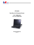
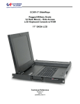
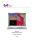
CPPM-8U201
Rack Mount LCD Display
20.1” UXGA LCD
User’s Manual
Revision B
Warranty
The product is warranted against material and manufacturing defects for two years from
date of delivery. Buyer agrees that if this product proves defective Chassis Plans’ is only
obligated to repair, replace or refund the purchase price of this product at Chassis Plans’
discretion. The warranty is void if the product has been subjected to alteration, neglect,
misuse or abuse; if any repairs have been attempted by anyone other than Chassis Plans;
or if failure is caused by accident, acts of God, or her causes beyond the control of Chassis
Plans. Chassis Plans reserves the right to make changes or improvements in any product
without incurring any obligation to similarly alter products previously purchased.
In no event shall Chassis Plans be liable for any defect in hardware or software or loss or
inadequacy of data of any kind, or for any direct, indirect, incidental or consequential
damages arising out of or in connection with the performance or use of the product or
information provided. Chassis Plans’ liability shall in no event exceed the purchase price
of the product purchased hereunder. The foregoing limitation of liability shall be equally
applicable to any service provided by Chassis Plans.
Return Policy
Products returned for repair must be accompanied by a Return Material Authorization
(RMA) number, obtained from Chassis Plans prior to return. Freight on all returned items
must be prepaid by the customer, and the customer is responsible for any loss or damage
caused by common carrier in transit. Items will be returned from Chassis Plans via
Ground, unless prior arrangements are made by the customer for an alternative shipping
method
To obtain an RMA number, call us at 858-571-4330. We will need the following
information:
Return company address and contact
Model name and model # from the label on the back of the display
Serial number from the label on the back of the display
Description of the failure
An RMA number will be issued. Mark the RMA number clearly on the outside of each box,
include a failure report for each board and return the product(s) to our San Diego, CA
facility:
Chassis Plans.
8295 Aero Place
Suite 200
San Diego, CA 92123
Attn: Repair Department
Trademarks
Liability
Disclaimer
IBM, PC/AT, VGA, EGA, OS/2 and PS/2 are trademarks or registered trademarks of
International Business Machines Corp.
Intel is a registered trademark of Intel Corporation.
MS-DOS and Microsoft are registered trademarks of Microsoft Corp.
All other brand and product names may be trademarks or registered trademarks of their
respective companies.
This manual is as complete and factual as possible at the time of printing; however, the
information in this manual may have been updated since that time. Chassis Plans
reserves the right to change the functions, features or specifications of their products at
any time, without notice.
Copyright © 2007 by Chassis Plans. All rights reserved.
E-mail: [email protected]
Web: www.chassisplans.com
Chassis Plans
8295 Aero Place • San Diego, CA 92123
Phone: (858) 571-4330 • Fax: (858) 571-6146 • Email: [email protected]
Chassis Plans
CPPM-8U201 Technical Reference
Table of Contents
Description ................................................................................................................................................ 1
Outline Drawing................................................................................................................................... 2
Part Number Matrix ................................................................................................................................... 3
Touch Screen Selection Options............................................................................................................. 3
Video Signal Input Selection Options...................................................................................................... 3
Installation ................................................................................................................................................. 4
Connecting the Display ........................................................................................................................... 5
Picture-In-Picture (PIP) ........................................................................................................................... 6
‘A’ and ‘D’ Controller ................................................................................................................................ 7
Description .............................................................................................................................................. 7
Front Panel Controls ............................................................................................................................... 7
‘A’ and ‘D’ OSD.......................................................................................................................................... 9
OSD Main Menu..................................................................................................................................... 9
Brightness ........................................................................................................................................... 9
Contrast .............................................................................................................................................. 9
Color Control ..................................................................................................................................... 10
Position ............................................................................................................................................. 10
Clock Phase ..................................................................................................................................... 10
Miscellaneous ................................................................................................................................... 10
Language .......................................................................................................................................... 10
Input Select ....................................................................................................................................... 10
‘V’ Controller ........................................................................................................................................... 11
Description ............................................................................................................................................ 11
Front Panel Controls ............................................................................................................................. 11
Sleep Mode ........................................................................................................................................... 12
‘V’ OSD ..................................................................................................................................................... 13
OSD Menu Organization ....................................................................................................................... 13
Display Menu ........................................................................................................................................ 14
PIP Menu .............................................................................................................................................. 15
PIP More Setting Sub Menu.............................................................................................................. 15
OSD Menu ............................................................................................................................................ 16
Audio Menu ........................................................................................................................................... 16
Misc Menu............................................................................................................................................. 17
Misc. Zoom Sub Menu ...................................................................................................................... 17
Misc. More Options Sub Menu.......................................................................................................... 18
’V’ Video Controller Details .................................................................................................................... 19
Features ................................................................................................................................................ 19
General Description .............................................................................................................................. 19
Controller Block Diagram ...................................................................................................................... 20
Video Mode Support ............................................................................................................................. 21
Specifications.......................................................................................................................................... 22
ENCLOSURE ........................................................................................................................................... 22
DISPLAY ................................................................................................................................................. 22
DISPLAY RESOLUTION ............................................................................................................................. 22
On Screen Display ................................................................................................................................ 22
Regulations ........................................................................................................................................... 22
Connectors:........................................................................................................................................... 23
Power Consumption.............................................................................................................................. 23
Environmental ....................................................................................................................................... 23
Shipping ................................................................................................................................................ 23
Chassis Plans
CPPM-8U201 Technical Reference
Description
The CPPM-8U201 is a high performance rack mount 8U 20.1" TFT LCD display with native UXGA 1600 x 1200
resolution. The display offers 250nit brightness, 500:1 contrast, and 89 degree viewing angle for exceptional
viewability. An anti-glare hard coating minimizes reflections making images that much clearer. The aspect ratio is
4:3 with a Pixel Pitch of only 0.255mm. It will display 16.7 million colors (True Color).
With only 3” of depth, the CPPM-8U201 is perfect for rack, wall, panel, or kiosk installations. It can be used in
Industrial, Commercial, Military, or Broadcast applications. Its lightweight but rugged aluminum construction makes
it perfect for mobile installations.
The CPPM-8U201 provides multiple signal input options including aRGB, DVI-D, NTSC, Pal S-Video and
Composite Video. Picture-In-Picture is supported with OSD control of the source. An optional 3Watt dual channel
audio amplifier is included with input and output jacks for connecting user provided speakers.
The display is offered with optional Capacitive and Resistive Touch Screens with either serial or USB output.
As with all Chassis Plans products, a wide variety of custom options are available including paint color, customer
logo, touch screens, contrast filters, transmissive daylight modification, hard coated vandal shields.
ENCLOSURE
20.1” UXGA 1600x1200 TFT LCD
8U (19.97”) x 3” deep
Rugged all aluminum construction
Designed to Satisfy Military, Industrial and
Commercial Requirements
Compact Enclosure for Limited Depth Installation
VIDEO CONTROLLER
Standard aRGB, DVI-D, S-Video and Composite
Video Inputs
OSD (On Screen Display) for Monitor Setup and
Control
Picture-in-Picture
Audio Input and Output with Built-In Amplifier
DISPLAY
Largest LCD Panel that can fit within the standard
rack constraints in 1U.
20.1” Diagonal Active Matrix UXGA TFT LCD
Features LG Technology
1600 x 1200 @ 60Hz Native Resolution
89 deg Viewing Angle
500:1 Contrast Ratio
250cd/m2 Brightness
OPTIONAL FEATURES / OPTIONS
Transflective LCD for Daylight Use
Enhanced Backlighting
Protective Glare Filters
Customer Specified Paint Color
Customer Logo
The CPPM-8U201 is offered with two different controllers depending on the input signal selection.
The ‘A’ (aRGB only) and ‘D’ (aRGB and DVI-D) inputs have slightly different front panel controls and the OSD is
simplified as compared to the higher end ‘V’ (aRGB, DVI-D, Composite, S-Video) controller.
The following Outline Drawing shows common features, though some of the input signal connectors will be missing
on the ‘A’ and ‘D’ controller versions that do not support Composite and S-Video inputs nor audio.
Page 1
Outline Drawing
Page 2
Front View
20.22
Top View
13.97
0
.86
4.36
9.61
13.11
Back View
Audio In
CVS In
S−Video In
Audio Out
Cable Anchor Points
DC Power
Input
DVI−D In
aRGB In
Touch Controller Out
USB or Serial
Bottom View
Side View
Isometric View
Chassis Plans
CPPM-8U201 Technical Reference
Chassis Plans
CPPM-8U201 Technical Reference
Part Number Matrix
CPPM-8U201-TS where ‘T’ designates the Touch Screen option and ‘S’ designates Input Signals.
Touch Screen Selection Options
‘T’
1
2
3
4
14
Touchscreen Type
Capacitive
Capacitive
Resistive
Resistive
No Touchscreen
Touchscreen Interface
Serial
USB
Serial
USB
Video Signal Input Selection Options
‘S’
A
D
V
Video Input Signal Types
aRGB
aRGB, DVI-D
aRGB, DVI-D, S-Video, CVS
Note
The controllers inside the display are different for the ‘A’/’D’ inputs versus the ‘V’ inputs.
This manual includes sections for the ‘A’ and ‘D’ Controllers and the ‘V’ Controller.
Make sure you reference the proper section for adjusting your OSD.
Page 3
Chassis Plans
CPPM-8U201 Technical Reference
Installation
To mount the CPPM-8U201 in a rack, it is first important you identify the correct holes to mount to. Please see the
following illustration. Note that a ‘U’ starts between the holes that are ½” apart. One very common problem is
trying to install into the wrong holes. Thus the bottom edge of the display would be placed between the holes ½”
apart.
Because there are multiple styles of racks, we can’t provide detailed instructions on mounting the equipment.
However, there are general instructions at http://www.chassis-plans.com/PDF/Rack_Slide_Use.pdf for rack
installation which should help.
Rack Mounting Hole Spacing
See the drawing above (page 2) for the distance between the rack mounting holes on the display.
Page 4
Chassis Plans
CPPM-8U201 Technical Reference
Connecting the Display
The CPPM-8U201 provides for analog, digital, composite and S-Video video inputs as well audio input and output.
Note
Connector configuration is dependant on the particular model. Not all models will have all connectors.
Legend
Function
Connector
Audio L / Audio R
Audio Inputs for CVS and S-Video
RCA Plugs
CVI
Composite Video Input (CVS)
RCA Plug
S-Video
S-Video Input
4-Pin Mini Din
Audio Out L / R
Audio Output from Amplifier
3.5mm Mini Stereo Jack - Female
aRGB
aRGB Video Inputs
HD15
DVI-D
DVI-D Video Input
DVI-D Connector
15VDC
Power Input, 15VDC
4-Pin Power Plug Receptacle
Touchscreen
Touchscreen Output
DB9 or USB (depending on model)
Video and Audio Connections
Audio In
CVS In
S−Video In
Audio Out
DC Power
Input
DVI−D In
aRGB In
Touch Controller Out
USB or Serial
Signal Connectors
The CPPM-8U201 provides a front panel Source selection button for selecting which input signal is to be displayed.
In addition, Picture-In-Picture is supported where the S-Video or Composite video inputs can be displayed as a
small window on top of the aRGB or DVI-D inputs.
An audio amplifier is provided with a computer input source and 2 RCA audio inputs for right and left channel. The
audio channel can be selected via the OSD for the computer input or the RCA video input (PIP). There is no
provision to output sound from one RCA input source to both speakers.
Page 5
Chassis Plans
CPPM-8U201 Technical Reference
Picture-In-Picture (PIP)
The CPPM-8U201 with the ‘V’ controller supports PIP. The PIP window can be sized to Small (approx 1.4x2.0”),
Medium (2.9x4.0”) or Large (4.3x5.6”). There are 5 preset PIP window positions or the window can be moved to a
user selected position through the OSD menus. The PIP window is used to put a smaller video feed window on top
of a full computer display. The PIP button on the front panel can be used to select the video feed to display and the
size.
The PIP source can only be S-Video or Composite input on top of either aRGB or DVI-D. The display will not use
either the aRGB or DVI-D as a PIP source. Setting the primary input to either Composite or S-Video disables the
PIP function.
The PIP window turns off when the monitor enters sleep mode, is turned off with the front Power control or is
stowed flat into the rack. To re-establish the PIP window, press the PIP button on the front panel and select the
desired input source and size using the + or – buttons.
Note
The default PIP source is TV. Whenever PIP is disabled by turning off the monitor or entering sleep
mode, the PIP input source will revert back to TV. After pressing PIP on the front panel, push either the
▲ or ▼ buttons to change to the PIP input selection Quick Menu and then + or ─ to change to the
desired input source.
Page 6
Chassis Plans
CPPM-8U201 Technical Reference – ‘A’ & ‘D’ Controller
‘A’ and ‘D’ Controller
Description
The ‘A’ controller provides for only aRGB input while the ‘D’ controller provides for both aRGB and Digital DVI-D
input. The OSD menus are different than those for the ‘V’ controller which provides for aRGB, Digital, Composite
and S-Video inputs. Users with the ‘V’ controller should see the next section.
Front Panel Controls
The On Screen Display (OSD) is adjusted as follows:
1.
2.
3.
4.
Press the Menu Button located on the front of the monitor.
Use the buttons described below to maneuver around the Menu.
Select the desired OSD Menu from the Menu Screen Shots below to make the desired adjustment(s).
Press the Auto/Exit button to exit out of the OSD Menu when complete or wait for the OSD window to
automatically close as set by the OSD Time Out setting.
•
Power: Turns the Unit On and Off
Green
Red
Amber
Off
•
•
•
•
•
Normal Operation
Power On but no input
signal
Power On and either
syncing to new input source
or input source is out of
range
No power or display turned
off
Quick Menu’s
A Quick Menu pops up by touching a single button.
Display Auto Adjust
Pressing Auto/Exit will perform a auto display adjustment
when in aRGB mode. This automatically adjusts the Phase
and Clock for the best displayed image.
Menu/Select: Enters the OSD
menu and sub menus (Press
once to enter main menu,
press again to enter a sub
menu) and accepts a display
parameter change.
Auto/Exit: With no OSD showing,
automatically adjusts the
display parameters for Clock
and Phase in aRGB mode.
When the OSD is displayed,
exits the current menu.
Left/Decrease: Moves a control bar
to the left or the cursor down
when selecting a menu.
Right/Increase: Moves a control
bar to the right or the cursor up
when selecting a menu.
Source: Alternates between the two
video input sources - aRGB
(VGA) and DVI-D.
Front Panel Controls
Page 7
Chassis Plans
CPPM-8U201 Technical Reference – ‘A’ & ‘D’ Controller
To save your changes, press the front panel Menu/Select button or Auto/Exit. Alternatively, changes are saved if
no buttons are pressed and the OSD times out returning back to the display.
There is a Factory Reset function under the Misc Adjustments Menu (bottom left ETC symbol) should you
completely screw things up and want to start over. Select the RECALL function in the Miscellaneous menu.
Note – Pressing Source with the OSD displayed will over-ride the OSD and change the input source. When a
valid signal is detected, the front panel LED will turn green.
Note – Pressing Source with the ‘A’ input (aRGB only) will change the internal source to Digital. However, a
digital input is not available and nothing will be displayed.
Page 8
Chassis Plans
CPPM-8U201 Technical Reference – ‘A’ & ‘D’ Controller
‘A’ and ‘D’ OSD
The CPPM-8U201 provides for On Screen Display (OSD) of the controls to adjust the display parameters such as
brightness, contrast, etc. The display controller stores the settings in non-volatile memory so they are saved even
when power is turned off or removed.
To enter the OSD, press the front panel Menu/Select button. Then use the Left/Decrease and Right/Increase
buttons to scan between each of the menu choices. When the desired menu item is selected, again press
Menu/Select to either bring up the control bar or the underlying sub menu.
If a control bar is brought up, use the Right/Increase or Left/Decrease buttons to change the level. Press
Menu/Select to accept the change or simply press Auto/Exit to accept the change and exit that menu.
If a sub menu is brought up, use the Left/Decrease and Right/Increase buttons to navigate the sub menu and
again use Menu/Select to change to the next menu or control.
Repeatedly pressing Auto/Exit will eventually exit the OSD or you can wait the number of seconds the OSD Timer
is set for to automatically exit the OSD.
Note in the Main Menu, the current resolution, horizontal and vertical frequencies are displayed. The bottom of the
Main Menu shows the controller firm ware revision.
OSD Main Menu
The main OSD menu is shown below.
Brightness
Underlying bar control to adjust the display brightness
Contrast
Underlying bar control to adjust the contrast or distinction of the display.
Page 9
Chassis Plans
CPPM-8U201 Technical Reference – ‘A’ & ‘D’ Controller
Color Control Underlying menu to control the color balance of the display (aRGB only)
User
Bluish
Reddish
Underlying sub menu to control Red, Green and Blue
Select to make the display ‘colder’
Select to make the display ‘warmer’
Position Underlying menus to control horizontal and vertical position of the display (aRGB only)
H Position Underlying bar control to change the overall horizontal position of the image.
V Position Underlying bar control to change the overall vertical position of the image.
Clock Phase
Underlying menu to control the clock rate and phase of the dot clock
Phase
Clock
Underlying bar control to change the overall horizontal position of the image.
Underlying bar control to change the overall vertical position of the image.
Miscellaneous Underlying menus to control the display parameters versus image parameters
Recall
OSD Time
OSD Position
Auto Color
Auto Adjust
Select to Recall the factory Default Settings
Underlying menu to select the OSD timeout setting
Underlying menus to move the OSD display horizontally and vertically
Select to automatically adjust the display color (aRGB only)
Select to automatically adjust display timing parameters for best fit to frequency,
resolution, etc. Same effect as pressing front panel Auto/Exit button. (aRGB only)
Language
Underlying menu to control select the OSD language
Input Select
Underlying menu selects aRGB versus Digital input source. Same as Source button on front panel.
Note
Two menus are grayed out between Language and Input Select as those features are not enabled on this
display.
Page 10
Chassis Plans
CPPM-8U201 Technical Reference – ‘V’ Controller
‘V’ Controller
Description
The ‘V’ controller applies to high end displays with aRGB, Digital DVI-D, Composite and S-Video inputs. The ‘A’
controller provides for only aRGB input while the ‘D’ controller provides for both aRGB and Digital DVI-D input.
Users with the ‘A’ and ‘D’ controller should see the previous section for OSD menus.
Front Panel Controls
The On Screen Display (OSD) is adjusted as follows:
1.
2.
3.
4.
Press the Menu Button located on the front of the monitor.
Use the buttons described below to maneuver around the Menu.
Select the desired OSD Menu from the Menu Screen Shots below to make the desired adjustment(s).
Press the Menu Button to exit out of the OSD Menu when complete or wait for the OSD window to
automatically close as set by the OSD Time Out setting.
•
•
•
•
•
•
•
•
Power: Turns the Unit On and Off
Menu/Exit: Enters and Exits the
menu and sub menus (Press
once to enter main menu,
press again to enter a sub
menu, press again to exit.
PIP: Brings up the Picture-In-Picture
Function Menu without having
to enter the Menu Key.
(▼) Arrow Down: Moves you Down
in the displayed menu
(▲) Arrow Up: Moves you Up in
the displayed menu
(─) Minus Sign: Decreases a
Function Level (Moves you
Left in the displayed menu).
(+) Plus Sign: Increases Function
Level (Moves you Right in the
displayed menu).
Source: Scrolls through the
different video sources.
Includes aRGB (VGA), DVI-D,
CVBS (Composite), SVHS (SVideo), TV (not available).
Quick Menu’s
A Quick Menu pops up by touching a single button. For
example by touching the minus button you bring up the
Volume’s Quick Menu and subsequently can adjust the Monitor
Volume level without have to go through the Main Menu, then
scrolling to the Volume Tab, moving to the Volume Level and
then making the adjustment.
Picture in picture Quick
Menu.
PIP: Brings up the PIP Menu
(V) Down Arrow: Toggles
between PIP source and
PIP On/Off/Size
(-) Minus Sign: Moves your
selection of Source or
Size Backward
(+) Plus Sign: Moves your
selection of Source or
Size Forward
Volume Quick Menu
(+) Brings up the Menu and
increases volume level
(-) Brings up the Menu and
decreases the volume
level
Display Auto Adjust
Pressing (+) and (-)
simultaneously will perform a
auto display adjustment
when in aRGB mode.
Front Panel Controls
To save your changes, press the front panel Menu/Exit button. Alternatively, changes are saved if no buttons are
pressed and the OSD times out returning back to the display.
There is a Factory Reset function under the Misc Adjustments Menu should you completely screw things up and
want to start over. See the right most Misc tab, More Options sub menu, Factory Reset.
Page 11
Chassis Plans
CPPM-8U201 Technical Reference – ‘V’ Controller
Note – Pressing Source with the OSD displayed will over-ride the OSD and change the input source. Source
scans, in order, aRGB, DVI-D, TV, CVBS, SVHS. It is normal for the display to hang in the SVHS mode
while trying to change the source as the controller scans available SVHS modes. When a valid signal is
detected, a small window above the source indicator will display the resolution, frequency, and controller
mode.
Sleep Mode
The display will enter sleep mode (turn off) if there is no input signal to the selected input mode. The delay to enter
Sleep Mode when the signal is not valid is approximately 6 seconds. When in sleep mode, the Power LED will
flash green. Pressing the Power button or Source button will exit the Sleep Mode and the display will scan the
selected input port for a signal. If no signal is present, the display will once again enter Sleep Mode. Note that
having a signal present on another port will not prevent the display from going into Sleep Mode if no signal is
present on the selected port. The display will only scan the selected port and does not auto-scroll through the other
ports.
Note that you can bring up the OSD menu when the display is brought out of Sleep Mode port but the OSD will
disappear when the display again enters Sleep Mode after not finding a signal.
Entering Sleep Mode will disable the PIP and revert to a TV PIP default. Use the front panel PIP to select the PIP
source and size to again display the PIP window. Alternatively, use the OSD to enable PIP.
Page 12
Chassis Plans
CPPM-8U201 Technical Reference – ‘V’ Controller
‘V’ OSD
The CPPM-8U201 provides for On Screen Display (OSD) of the controls to adjust the display parameters such as
brightness, contrast, etc. The menus are context sensitive in that there are adjustments specifically for each
Source Input type (analog aRGB, digital DVI-D, S-Video and Composite). This allows you to tune the display for
each type of input without having to retune when changing the Source selection. The display controller stores the
settings in non-volatile memory so they are saved even when power is turned off or removed.
In the following menus, there are many common features and selections between each type of input. However,
some adjustments may not pertain to a particular input signal type so those adjustments are not shown.
Note
The display controller provides a TV function which is not utilized in theCPPM-8U201. While the
TV menu selections are available in the OSD, none of the TV functions work. Adverse display
behavior may be observed if the TV settings are changed and it is advised they be left set to the
default setting.
OSD Menu Organization
While different adjustments are available for each of the different input types, the menus are similarly organized
and the adjustments have the same effect.
Display Brightness (Fine and Course), Contrast, Phase, Frequency, H Position, V Position
PIP
Brightness, Contrast, Sharpness, Color, Tint, PIP Source, PIP Size, PIP More Settings (sub menu)
PIP More Settings – H Position, V Position, PIP Position Preset
OSD
OSD Background, OSD Time Out, OSD Position Preset, OSD H Position, OSD V Position, OSD
Language, Controller Firmware Revision
Audio
Volume, Treble, Bass, Balance, Audio Preset, Mute, Sound Swap
Misc.
Auto Adjustment, Source, Sleep Time, Sleep Time Remaining Indicator, Room Lighting, Freeze Frame,
Zoom Settings (sub menu), More Options (sub menu)
Zoom Settings – Zoom, Zoom H Pan, Zoom V Pan
More Options – Color Temp, Sharpness Filter, Scale Mode, Factory Reset
Note
An additional TV tab will display on the right if TV is selected for the Main Source or PIP Source.
It is recommended that TV not be selected or used for any adjustment.
Page 13
Chassis Plans
CPPM-8U201 Technical Reference – ‘V’ Controller
A typical menu appears as follows:
Display Menu
Adjustment
Brightness – Fine
Brightness – Course
Contrast
Phase
Frequency
H Position
V Position
Sharpness
Color
Tint
Brightness
Contrast
Phase
Frequency
H Position
V Position
Sharpness
Color
Tint
aRGB
●
●
●
●
●
●
●
Applicability
DVI-D
CVHS
●
●
●
●
●
●
●
●
●
CVBS
●
●
●
●
●
●
Top is Fine Adjustment and bottom is Course Adjustment. Adjusts the brightness
of the screen. Image brightness (ADC for analog signals, PW for digital).
Adjusts distinction (Image noise clearness). Image contrast (ADC for analog, PW
for digital).
Adjusts the phase signal sample. Use it to fine tune to eliminate noise or
overlapping lines.
Adjusts horizontal size of the screen by increasing or decreasing number of picture
elements.
Shifts displayed image left or right.
Shifts displayed image down or up.
Adjusts the sharpness of the picture.
Adjusts the display color saturation of the screen. (Video only, TV not available).
Used to adjust the display hue adjustment of the screen. (Video only, TV not
available).
Page 14
Chassis Plans
CPPM-8U201 Technical Reference – ‘V’ Controller
PIP Menu
Adjustment
Brightness
Contrast
Sharpness
Color
Tint
PIP Source
PIP Size
PIP More Settings (sub menu)
Brightness
Contrast
Sharpness
Color
Tint
PIP Source
PIP Size
PIP More Settings
aRGB
●
●
●
●
●
●
●
●
Applicability
DVI-D
CVHS
●
●
●
●
●
●
●
●
CVBS
Adjusts the brightness of the PIP display.
Adjust distinction (Image noise clearness).
Adjusts the sharpness of the PIP display.
Adjusts the display color saturation of the PIP display. (Video only, TV not available).
Used to adjust the display hue adjustment of the screen. (Video only, TV not
available).
S-Video (SVHS) or Composite (CVS) (TV not available)
Small, Medium, Large, and Off.
See Below.
PIP More Setting Sub Menu
Adjustment
H Position
V Position
PIP Position Preset
aRGB
●
●
●
Applicability
DVI-D
CVHS
●
●
●
CVBS
H Position
Move the PIP from Left Edge (0) to Right Edge (100)
V Position
Move the PIP from Bottom Edge (0) to Top Edge (100)
PIP Position Preset Top Left, Top Right, Middle of Screen, Bottom Left, Bottom Right.
Note
The PIP menus are not available (tab not shown) when the primary input source is set to CVHS or CVBS.
Page 15
Chassis Plans
CPPM-8U201 Technical Reference – ‘V’ Controller
OSD Menu
Adjustment
OSD Background
OSD Time Out
OSD Position Preset
OSD H Position
OSD V Position
OSD Language
Version 29A 1.00
OSD Background
OSD Time Out
OSD Position Preset
OSD H Position
OSD V Position
OSD Language
Version 29A 1.00
aRGB
●
●
●
●
●
●
●
Applicability
DVI-D
CVHS
●
●
●
●
●
●
●
●
●
●
●
●
●
●
CVBS
●
●
●
●
●
●
●
Opaque or Translucent
Sets the time (5 to 60 seconds) the OSD will be displayed without any user input.
Top Left, Top Right, Middle of Screen, Bottom Left, Bottom Right
Move OSD from Left Edge (0) to Right Edge (100)
Move OSD from Bottom Edge (0) to Top Edge (100)
English, French, Italian, German, two Asian languages
LCD Controller Firmware Revision
Audio Menu
Adjustment
Volume
Treble
Bass
Balance
Audio Preset
Mute
Sound Swap
Volume
Treble
Bass
Balance
Audio Presets
Mute
Sound Swap
aRGB
●
●
●
●
●
●
●
Applicability
DVI-D
CVHS
●
●
●
●
●
●
●
●
●
●
●
●
●
CVBS
●
●
●
●
●
●
Adjusts the audio output level.
Adjusts the midrange tone of the audio output.
Adjusts the base tone of the audio output.
Adjusts audio output to Right or Left bias.
Select preset Treble and Base settings (User, Movie, News and Standard).
Silence audio output. Off allows sound output. On mutes the sound (sound off)
Change audio input source from Main PC Audio in to PIP.
Audio Notes:
1. Treble and Bass will be ‘grayed out’ and not adjustable when Audio Preset is set to Movie, News or
Standard.
2. Sound Swap is not available when CVHS or CVBS are selected as the input because PIP is disabled in
that configuration.
3. A video signal must be present at CVHS or CVBS for the video sound input to function. Connecting an
audio source to the either the Audio Left or Audio Right without a corresponding video input will not work.
4. Pressing the front panel + or – control will raise or lower the volume without invoking the OSD. There is no
front panel Mute control.
Page 16
Chassis Plans
CPPM-8U201 Technical Reference – ‘V’ Controller
Misc Menu
Adjustment
Auto Adjustment
Source
Sleep Time
Room Lighting
Freeze Frame
Zoom Settings (sub menu)
More Options (sub menu)
aRGB
●
●
●
●
●
●
●
Applicability
DVI-D
CVHS
●
●
●
●
●
●
●
●
●
●
●
CVBS
●
●
●
●
●
Automatically adjusts the screen resolution and sync to the incoming signal.
(aRGB Source Only)
Source
Selects the video input signal source (aRGB, DVI-D, S-Video, and Composite
Video).
Sleep Time
Adjust (5 to 120 minutes) to set a desired time for monitor to go to sleep.
Sleep Time remaining Indicates remaining time until monitor goes to sleep (Grayed out until sleep timer is
activated.
Room Lighting
Bright, Normal, Movie changes the display brightness slightly with Movie being
lowest.
Freeze Frame
Retains the image on the monitor, including PIP.
Zoom Settings Menu See Below
More Options Menu See Below
Auto Adjust
Misc. Zoom Sub Menu
Adjustment
Zoom
Zoom H Pan
Zoom V Pan
Zoom
Zoom H Pan
Zoom V Pan
aRGB
●
●
●
Applicability
DVI-D
CVHS
●
●
●
●
●
●
CVBS
●
●
●
Zooms into the center of the displayed image, including PIP. If the PIP is not
located at the center of the display, it will be zoomed off the edge and will no
longer be visible. The maximum zoom factor is approximately 16:1.
Pans the zoomed image left or right.
Pans the zoomed image up or down.
Notes:
1. Zoom H Pan and Zoom V Pan will be grayed out if Zoom is set to 0.
Page 17
Chassis Plans
CPPM-8U201 Technical Reference – ‘V’ Controller
Misc. More Options Sub Menu
Adjustment
Color Temp
Red Temp
Green Temp
Blue Temp
Sharpness Filter
Scale Mode
Factory Reset
Color temp
User color
Sharpness Filter
Scale Mode
aRGB
●
●
●
●
●
●
●
Applicability
DVI-D
CVHS
●
●
●
●
●
●
●
●
●
●
●
●
●
●
CVBS
●
●
●
●
●
●
●
Adjust the Red/Green/Blue bias for Color Temperature (5500K, 7500K, 9300K and
User). Default value is set at 7300K.
You can adjust red, green and blue setting for user Color Temperature (grayed out
unless Color Temp set to User).
Adjust the picture Sharpness (Normal, Sharp, Sharpest, Soft, and Softest).
Adjust the output image size from the image scalar to be larger, smaller or same
as the display device.
Fill All – fill screen.
Fill Aspect – fill screen but maintain aspect ratio.
One To One – display image in original size (no scaling).
Zoom – convert letterboxed video to full screen.
Anamorphic – Squeezes a 16:9 image into a 4:3 space. Available only for
video inputs.
Video Game Zoom – Zooms display in slightly to remove game borders.
Available only for video inputs.
Factory Reset – Resets all settings back to factor settings including OSD
Language to English. Press (+) to reset.
Page 18
Chassis Plans
CPPM-8U201 Technical Reference – ‘V’ Controller
Video Controller Details
Features
• State of the art high performance picture quality design
• Analog RGB / DVI / CVBS (x1) & SVHS (x1) with NTSC, PAL, SECAM /Audio input (x3) / TV / Remote
control / Speaker out (x1)
• Optional input combination, e.g., PC Monitor only, PC Monitor with TV
• Full CRT multi-sync monitor compatibility
• Multi-sync capability up to UXGA resolution @ 75Hz, compatible standard DOS, VGA, SVGA, XGA and
SXGA VESA timing
• Expand DOS, VGA, SVGA ,XGA and SXGA to full screen display
• True color (16.7M) data processing and display driving
• Single control operated & transparent On-Screen-Display (hereafter ‘OSD’) user interface
• Full control of all relevant display and interface parameters via OSD
• Multi language support
• VESA DDC1/2B compliant
• Compatible with VESA DPMS power saving modes
• +12VDC single power: 48watts AC/DC power adapter recommended.
• Operating temperature: 0 to 50°C
• The 3watt x 2 ch. @ 7 ohms audio capability with treble, bass, volume and mute control through either
OSD or remote controller.
• OSD & Power switch board
• Optional TV tuner : NTSC, PAL and SECAM
• LCD Voltage select on Board : 5.0V, Adapter V, 12V
General Description
The DIT201001C Controller is an advanced TFT LCD Monitor Control Board. This design enables a
full conventional CRT monitor and/or video & audio replacement with a large size Active Matrix LCD
module. It is suitable for video resolution up to UXGA @ 75Hz in all video modes, the full display area
of the module is used.
The DIT201001C Controller is designed to act as a full monitor and/or video & audio interface. Besides the
main functionality of an analog and digital video interface, also CVBS (x1), SVHS (x1) and
stereo audio amplifier with 4 inputs.
Page 19
Chassis Plans
CPPM-8U201 Technical Reference – ‘V’ Controller
Controller Block Diagram
Page 20
Chassis Plans
CPPM-8U201 Technical Reference – ‘V’ Controller
Video Mode Support
The CPPM-8U201 monitor can support any video mode within the following input constraints:
• Signal sample frequency with the input ≤ 80kHz
• Horizontal sync frequency between 30KHz and 60KHz.
The modes are detected when presented to the input and previous alignments for setup are automatically
recalled. A true multi-sync monitor emulation is implemented.
The factory preset supported modes include:
Notes:
1. All mentioned modes are non-interlaced. The maximum and minimum frame rates are determined
the by the TFT LCD.
2. Factory preset modes are overwritten by additional user alignments for automatic recall. At all times
it remains possible to recall the initial factory presets.
Video Mode Support
Page 21
Chassis Plans
CPPM-8U201 Technical Reference – ‘V’ Controller
SPECIFICATIONS
ENCLOSURE
8U x 19" (wide) x 3" (deep) (Not including connectors)
Weight: 30lbs
Color: Powder coated black, light texture (Custom colors and logos available)
DISPLAY
LG.Phillips LM201U04 20.1" TFT LCD w/ antiglare hard coating
Display area: 408mm x 306mm
Display Colors: 16.7 Million
Response Time: 16mS
Viewing Angle: 89/89/89/89 deg
Contrast Ratio: 500:1 typical
Brightness: 250cd/m2 typical
Pixel Pitch: 0.255mm x 0.255mm
Power Management: EPA Energy Star, VESA DPMS
DISPLAY RESOLUTION
Max Resolution:
D-Sub: Analog UXGA 1600 x 1200 @ 75Hz
DVI: UXGA 1600 x 1200 @ 60Hz
Recommended Resolution: DVI UXGA 1600 x 1200 @ 60Hz
19 Display Modes VGA to UXGA
Horizontal Frequency: 15-80KHz Automatic
Vertical Frequency: 60-75Hz Automatic
On Screen Display
Contrast
Brightness
Autosetting
Clock / Phase
Horizontal & Vertical Position / Expansion / OSD
Text & Graph Mode Selection
Color Temp
Recall
Audio Function
PIP Source
Regulations
FCC-A, CE
Optional UL, CSA, TUV
Page 22
Chassis Plans
CPPM-8U201 Technical Reference – ‘V’ Controller
Connectors:
aRGB:
DVI-D:
Composite:
S-Video In:
Audio In:
Audio Out
DC Power In:
Touch Screen:
15-pin high density DB15
DVI-D 23-pin female
BNC
4-Pin Mini Din
RCA (x2)
3.5mm Stereo Jack, Female (x2)
2-Pin Power Plug
DB9 or USB (depending on model)
Power Consumption
Normal: 60W (front LED Green)
Power Input: 100-240VAC, 50/60Hz 1.2A
Power Cord: Wall-outlet type or PC-outlet type
The power supply is a Sunny model STD-1504 or equivalent "brick" measuring 2.5"(W) x 1.2"(H) x 4.3"(L). The
output is 15VDC at 4.0A. The DC cord length is approximately 36".
Environmental
Operating conditions:
Temperature: 0 to 50 deg C
Humidity:
10% to 90% non-Condensing
Altitude:
12,000 feet
Storage conditions:
Temperature: -25 to 60 deg C
Humidity:
5% to 95% non-Condensing
Altitude:
40,000 feet
Shipping
Weight: 39lbs
Shipping Box - 40” x 23” x 6”
Page 23