1
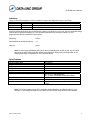
INDUSTRIAL DATA COMMUNICATIONS
USER GUIDE
DLM4100
Compact Dial-Up Modem
It is essential that all instructions contained in the User Guide are followed precisely to ensure proper operation of equipment.
Product User Guide
DATA-LINC GROUP
PN 161-09977-001B
DLM4100 User’s Manual
Operating Instructions
The DLM4100 is a compact dial-up modem designed and manufactured to operate in full industrial applications.
It is powered with an input voltage range of +8V to +15VDC. A 120VAC to unregulated 12VDC wall transformer
power supply has been provided (24VDC versions also available). The operating temperature range of this
device is 0° to 70° C. The (ET) Extended Temperature model is rated at -40° to +85° C.
Any device connected to the modem must be set for a 10-bit word such as:
Data Bits
Stop Bits
Start Bits
8
1
1
7
1
1
7
2
1
Parity
None
Even/Odd
None
Connections
Cable connections are all made on one end of the unit. The DB-9 female (see pinout below) on the left is for the
RS-232 data.
Note: RS-485 and RS-422 models are also available
The supplied wall transformer plugs into the barrel jack for supplying power to the unit. For alternate power
methods, see barrel jack pinout below. The RJ-11 jack on the right is the telephone line connection. Only the
center two lines are used.
DB-9 for the RS-232 data port. The port is setup as a DCE device and the pins are:
DB-9 Female
Description
Pin 1
Carrier Detect
Pin 2
Data Out of modem RS-232 port
Pin 3
Data Into modem RS-232 port
Pin 4
N/C
Pin 5
Ground
Pin 6
N/C
Pin 7
N/C
Pin 8
N/C
Pin 9
N/C
The 12 VDC power jack plug for input power.
12VDC (P-5 Barrel Jack)
Center Pin
Outer Ring
P/N 161-09977-001B
+8 to 15VDC in
Ground
2
DLM4100 User’s Manual
Indicators
There are four LED’s displayed out the front panel for status and diagnostics they are as follows:
(P) Power
Red
On indicates that the board is receiving power
(C) Carrier
Amber
On indicates that a connection has been made to another DLM4100
( I ) Data In
Yellow
On indicates that data is flowing into the serial port
(O) Data Out
Green
On indicates that data is flowing out to the serial port
Since the DLM4100 has been pre-configured at the factory for typical PLC to PC use, the only command strings
required are for dialing and hanging up. The command instruction to be entered in either PC or PLC
programmed for dial-up operation are listed below:
Dial String:
ATDTx
Command Mode (escape sequence):
+++
Hang up:
ATH0
Note: Do not use any initialization string at all when commanding the modem to dial. Any command
other than the ATDT followed by the number being dialed can change the pre-configuration of the
DLM4100 and make it inoperative for PLC communications.
Specifications
Input Voltage
Current Consumption
Ring Voltage Detected
Ring Frequency Detected
Telephone Loop Current
Data Transmit Level
DTMF Transmit Level
Operating Temperature Range
Enclosure Material
Enclosure Dimension
Weight
+8 to 15 VDC
Max 260mA
38 to 150 RMS
15.3 to 68 Hz
20 to 100mA
-12 to –9.0 dBm
-2.5 dBm Avg. over 3 second interval
0° C to 70° C Standard Model
-40° C to 85° C Extended Temperature Model
18 gauge steel
9.0” x 5.0” x 1.5” over mounting flanges
1.68 lb.
.76 kg.
Note: The following pages are the AT Commands, Modem Registers, and Result codes for your
reference. In pre-configured systems from Data-Linc Group these values should not be changed.
P/N 161-09977-001B
3
DLM4100 User’s Manual
AT Commands
A- Answer Command – ATA forces the modem to immediately go off-hook and begin transmitting the
answer tone sequence.
Bn- Select Communications Standard – ATBn selects the modulation scheme used for connections
below 2400 bits per second.
n=0 Selects CCITT standards
n=1 Selects Bell standards
D- Dial Command – Below are the characters accepted in a dialing command.
0-9, #,* = Dialing Digits
L = Re-dial last number
P = Pulse dial
T = Tone dial
S=n = Dial stored number
W = Wait for dial tone
^ = Toggles state of calling tone
, = Pause for the duration of S8
@ = Wait for silence
! = Switch hook flash
; = Return to the command state
En- Command Echo – ATEn determines whether commands will be echoed back to the host.
n=0 Do not echo commands
n=1 Enable command echo
Hn – Switch Hook Control – ATHn opens and closes the modem’s hook switch.
n=0 Switch hook relay opens
n=1 Switch hook relay closes
Ln- Speaker Volume – ATLn Sets the amplitude of the modem’s audio output
n=0 Lowest speaker volume
n=1 Low speaker volume
n=2 Speaker remains on
n=3 Speaker off during dialing, on until carrier
Mn- Speaker Activity – ATMn determines when the modem’s audio output is active.
n=0 Speaker off
n=1 Speaker on until carrier received
n=2 Speaker remains on
n=3 Speaker off during dialing, on until carrier
P/N 161-09977-001B
4
DLM4100 User’s Manual
On- On Line – ATOn switches the modem from the command mode to the data mode.
n=0 Return on-line with no retrain
n=1 Initiate retrain returning on-line
Qn- Reponses – ATQn determines if the modem will issue responses
n=0 Send responses*
n=1 No responses
SR?- Interrogate Register – ATSr? request the current value in register Sr.
SR=n- Set Register Value – ATsr=n sets the value of register Sr to n
Vn- Result Codes – ATVn sets the modem to issue numeric or full word result codes
n=0 Numeric result codes
n=1 English word result codes
Wn- Connect Message Rate – ATWn determines whether the data rate reported in the Connect
response is the host date rate, the link data rate or whether both are provided along with the error control
and data compression protocols negotiated.
n=0 Send “Connect” at DTE rate
n=1 Report line speed, DTE speed and Link protocol
n=2 “Connect” reports Link speed
Xn- Result Code Set – ATXn selects which set of result codes the modem may send.
n=0 Result codes 0 to 4
n=1 Result codes 0 to 5 and 10
n=2 Result codes 0 to 6 and 10
n=3 Result codes 0 to 5, 7 and 10
n=4 Full result codes*
Zn- Reset – ATZn executes a soft reset to the modem and resets the modem configuration
n=0 Reset to user profile 0
n=1 Reset to user profile 1
&Cn- DCD Operation – AT&Cn determines the operation of the DCD output.
n=0 DCD is forced active
n=1 DCD indicates a valid carrier
P/N 161-09977-001B
5
DLM4100 User’s Manual
&Dn- DTR – AT&Dn determines how the modem will respond to changes to DTR
n=0 DTR is ignored by the modem
n=1 Enter command mode if DTR revoked
n=2 Disconnect if DTR revoked
n=3 Soft reset when DTR revoked
&Gn- Guard Tone – AT&Gn controls the guard tone produced by the modem
n=0 Guard tone disabled
n=1 Guard tone disabled
n=2 1800 Hz guard tone
&Kn- Flow Control – AT&Kn selects the flow control method used by the modem
n=0 Disabled
n=3 RTS/CTS
n=4 XON/XOFF
n=5 Transparent XON/XOFF
n=6 RTS/CTS and XON/XOFF
&Pn- Dial Pulse Make/break Ratio – AT&Pn determines the specific pulse dialing parameters used by the
modem
n=0 39/61% @ 10pps
n=1 33/67% @ 10pps
n=2 39/61% @ 20pps
n=3 33/67% @ 20pps
&Qn- Line Connection – AT&Qn determines if error control or data buffering are active on the link
n=0 Direct mode (no data buffering)
n=5 Use Error Correction
n=6 Normal Mode (speed buffering)
&Sn- DSR Operation – AT&Sn sets the operation of the DSR signal
n=0 DSR always active
n=1 DSR in accordance with V.25
&Tn- Test Modes – AT&Tn selects modem test modes
n=0 Exit test mode
n=1 Local analog loopback
n=3 Initiate local digital loopback
n=4 Respond to remote loop request
n=5 Deny remote loop request
n=6 Initiate a remote digital loopback
n=7 Remote digital loopback with self-test
n=8 Local analog loopback with self-test
P/N 161-09977-001B
6
DLM4100 User’s Manual
&Vn- View Configuration Profiles – AT&Vn permits the user to check on the modem’s current
configuration
n=0 View active profile & user profile 0
n=1 View active profile & user profile 1
&Wn- Store Active Profile – AT&Wn stores the current modem configuration in NVRAM.
n=0 Store active profile as profile 0
n=1 Store active profile as profile 1
&Yn- Recall Stored Profile – AT&Yn sets the stored modem configuration to be used after a hard reset
n=0 Recall profile 0 on power-up
n=1 Recall profile 1 on power-up
&Zn=x- Store telephone number “x” in memory location “n”
%En- Line Quality Monitor/Auto Retrain – AT%En determines if the modem will monitor line quality
during a connection and initiate a retrain if quality drops below acceptable levels.
n=0 Disabled
n=1 Enabled
n=2 Line quality, fall back, fall forward
%L- Read Received Signal Level – AT%L permits the user to read the magnitude of the receive signal in
dBm
%Q- Read Line Signal Quality – AT%Q permits the user to read the EQM value of the received signal
\Bn- Transmit Break – AT\Bn selects the duration of the break signal sent
Break=n x 100 msec.
\Gn- Modem Port Flow Control –
n=0 No modem port flow control
n=1 XON/XOFF port flow control
P/N 161-09977-001B
7
DLM4100 User’s Manual
\Kn- Break Control – AT\Kn determines how the modem will handle a break signal.
Break received from host with reliable link
n=0 Enter on-line command mode; do not transmit break
n=1 Purge buffers, immediately transmit break
n=2 Same as n=0
n=3 Immediately send break
n=4 Same as n=0
n=5 Send break in sequence with data
Break received from host with direct link
n=0 Immediately transmit break, then enter on-line command mode
n=1 Immediately send break
n=2 Enter command mode, but do not transmit break
n=3 Same as n=1
n=4 Same as n=0
n=5 Same as n=1
Break received from modem with normal link
n=0 Purge buffers, immediately send break to the host
n=1 Same as n=0
n=2 Immediately send break to the host
n=3 Same as n=2
n=4 Send break in sequence with data
n=5 Same as n=2
Host initiates break on reliable link
n=0 Purge buffers and immediately transmit break
n=1 Same as n=0
n=2 Immediately transmit break
n=3 Same as n=1
n=4 Transmit break in sequence with data
n=5 Same as n=4
\Nn- Error Control Selection -AT\Nn determines how the modem will handle error control negotiations
n=0 Normal mode, no error correction
n=1 Direct mode, no buffering, no error correction
n=2 Reliable mode, error correction required
n=3 V.42 Auto-reliable mode, accept either an error controlled or non-error controlled link
n=4 V.42 Reliable mode, LAPM required
n=5 MNP required
-Kn- MNP Extended Services – AT-Kn determines how the modem handles MNP10
n=0 No LAPM to MNP10 conversion
n=1 LAPM to MNP10 conversion
n=2 LAPM to MNP10 conversion but no MNP extended service during V.42 LAPM answer mode
detect
P/N 161-09977-001B
8
DLM4100 User’s Manual
+MS- Select Modulation – AT+MS sets the modulation and available data rates in the format shown below
AT+MS= a, b, c, d, e, f <CR>
a=Modulation type
B103- Bell 103 (300 BPS)
B212- Bell 212 (1200 BPS)
V21- V.21(300 BPS)
V22- V.22 (1200 BPS)
V22B- V.22bis (1200 or 2400 BPS)
V23- V.23 (1200 Tx/ 75 RX or 75 Tx/ 1200 Rx)
V32- V.32 (4800 or 9600 BPS)
V32B- V.32bis (4800 to 14400 BPS)
V34- V.34bis (16800 to 33600 BPS)
b= Auto detection
0- Automatic Negotiation Disabled
1- Automatic Negotiation Enabled
c= Minimum receive Data Rate (300 to 33600 BPS)
d= Maximum receive Data Rate (300 to 33600 BPS)
e= Minimum transmit Data Rate (300 to 33600 BPS)
f= Maximum transmit Data Rate (300 to 33600 BPS)
Modem Registers
S0 Answer on nth Ring: S0 sets the modem to automatically answer on the nth ring. Setting S0 to 0
disables automatic answer.
Range: 0 to 255
Units: Rings
Default: 0
S1 Ring Count: S1 is a read-only register showing the number of rings detected. If a ring is not detected
within 8 seconds, S1 reset to zero.
Range: 0 to 255
Units: Rings
Default: 0
S2 Escape Character: S2 determines the ASCII escape character. Values of 0-127 select valid ASCII
escape characters; values from 128-255 disable the escape sequence.
Range: 0 to 255
Units: ASCII Character
Default: 43
P/N 161-09977-001B
9
DLM4100 User’s Manual
S3 Carriage Return Character: S3 determines the ASCII character to serve as a carriage return to
terminate commands and modem responses.
Range: 0 to 127
Units: ASCII Character
Default: 13 (carriage return)
S4 line Feed Character: S4 sets the ASCII character to act as a line feed character in modem responses.
Range: 0 to 127
Units: ASCII Character
Default 10 (line feed)
S5 Back Space Character: S5 defines the ASCII character used as a back space to edit the command
line.
Range: 0 to 32
Units: ASCII Character
Default: 8 (back space)
S6 Dial Tone Wait Time: S6 determines how long the modem waits for dial tone before dialing begins. The
dial tone wait time cannot be set to less than two seconds.
Range: 2 to 255
Units: Seconds
Default: 2
S7 Wait for Carrier after Dialing: S7 determines how long the modem waits for a valid carrier signal after
dialing is completed.
Range: 1 to 255
Units: Seconds
Defaults: 50
S8 Comma Pause Time: S8 defines the duration of the pause initiated by a comma in the dialing string.
The pause is generally used when waiting for a second dial tone.
Range: 1 to 255
Units: Seconds
Default: 50
S9 Reserved
P/N 161-09977-001B
10
DLM4100 User’s Manual
S10 Carrier Off Disconnect Delay: S10 selects how long carrier must be lost before the modem
disconnects. Note: if S10 is smaller than the value of S9, the modem will not automatically disconnect on
loss of carrier.
Range: 1 to 255
Units: 0.1 Seconds
Default: 14
S11 Tone Dialing Speed: S10 sets the duration and spacing of the dialing tones. S11 does not affect the
pulse dialing rate.
Range: 50 to 255
Units: 1 Millisecond
Default: 95
S12 Escape Code Guard Timer: S12 sets the escape sequence guard timer. If characters are received
before or after the escape sequence, within the guard timer, the modem aborts the escape attempt and
remains in data mode.
Range: 0 to 255
Units: 0.02 Seconds
Default: 50
S14 General Bit-Mapped Options: S14 reflects the state of several “AT” commands.
Bit 0,4,6 not used
Bit 1
Bit 2
Bit 3
Bit 5
Bit 7
0=Echo Disabled (ATE0)
1=Echo Active (ATE1)
0=Send result codes (ATQ0)
1=No result codes (ATQ 1)
0=Numeric result codes (ATV0)
1=Full word result codes (ATV1)
0=Tone dialing selected (T)
1=Pulse dialing selected (P)
0=Answer
1=Originate
S16 Test Status: S16 shows the modem test status.
Bit 0
0=No local analog loopback
1=Local ALB active
Bit 2-7 not used
P/N 161-09977-001B
11
DLM4100 User’s Manual
S21 General Bit-Mapped Options: S21 reflects the state of several “AT” commands.
Bit 0-2 Not used
Bit 3-4 0=DTR ignored (&D0)
1=Enter command mode on DTR off (&D1)
2=Disconnect on DTR off (&D2)
3=Reset on DTR off (&D3)
Bit 5
0=DCD always active (&C0)
1=DCD on with carrier (&C1)
Bit 6
0=DSR always active (&C0)
1=DSR on when modem ready (&C1)
Bit 7
0=No disconnect on space (ATY0)
1=Disconnect on space (ATY1)
S22 General Bit-Mapped Options: S22 reflects the stat of several “AT” commands.
Bit 0-1 0=Low speaker volume (ATL0)
1=Low speaker volume (ATL1)
2=Moderate speaker volume (ATL2)
3=High speaker volume (ATL3)
Bit 2-3 0=Speaker off (ATM0)
1=Speaker off with carrier (ATM1)
2=Speaker always on (ATM2)
3=Speaker on during handshake (ATM3)
Bit 4-6 0=Basic result codes (ATX0)
4=Connect speed result codes (ATX1)
5=No blind dial (ATX2)
6=Busy detection (ATX3)
7=Full result codes (ATX4)
Bit 7
Not used
S23 General Bit-Mapped Options: S23 reflects the state of several “AT” commands.
Bit 0
0=Remote DLB disabled (AT&T5)
1=Remote DLB allowed (AT&T4)
Bit 1-3 0=Host interface at 300 BPS
1=Host interface at 600 BPS
2=Host interface at 1200 BPS
3=Host interface at 2400 BPS
4=Host interface at 4800 BPS
5=Host interface at 9600 BPS
6=Host interface at 19200 BPS
7=Host I/F at 38,400 BPS or higher
Bit 4-5 0=Even parity in use
1=Not in use
2=Odd parity in use
3=No parity in use
Bit 6-7 0=No guard tone (AT&G0)
1=No guard tone (AT&G1)
2=1800 Hz guard tone (AT&G2)
3=Not used
P/N 161-09977-001B
12
DLM4100 User’s Manual
S24 Sleep Mode Timer: S24 sets the length of time in seconds that the modem must be idle before
entering the low power, sleep mode. When S24 is set to 0, sleep mode is disabled.
Range:0 to 255
Units: seconds
Default: 0
S27 Pulse Dialing Bit-Mapped Options: S27 reflects the state of several “AT” commands.
Bit 0
0
1
0
1
0
0
1
3
0=Normal mode (AT&Q0)
1=Error control enabled (AT&Q5)
1=Direct mode (AT&Q6)
Bit 2, 4- 5, 7 Not used
Bit 6
0=CCITT Protocols (ATB0)
1=Bell Protocols (ATB1)
S28 Pulse Dialing Bit-Mapped Options: S28 stores the modem’s pulse dialing configuration.
Bit 0-2, 5-7 Not used
Bit 3-4 0=Make/Break ratio 39%/61%; 10 pulses per second (AT&P0)
1=Make/Break ratio 33%/67%; 10 pulses per second (AT&P1)
2=Make/Break ratio 39%/61%; 20 pulses per second (AT&P2)
3=Make/Break ratio 33%/67%; 20 pulses per second ( AT&P3)
S29 Hook Flash Timer: S29 determines the length of time the modem closes its off-hook relay on receipt
of the “I” dial modifier to simulate a switch hook flash.
Range: 0 to 255
Units: 10 Milliseconds
Default: 70
S30 Disconnect on Inactivity Timer: S30 sets the period the modem is idle before it disconnects. A 0
disables the inactivity timer.
Range: 0 to 255
Units: 10 Seconds
Default: 0
S31 General Bit-Mapped Options: S31 stores the status of various AT commands.
Bit 0
0=No single-line connect messages (AT\V0)
1=Single-line connect messages
Bit 1
0=No auto mode detection (ATN0)
1=Auto mode detection active (ATN1)
Bit 2-3 0=Report host speed (ATW0)
1=Report all parameters (ATW1)
2=Report modem speed only (ATW2)
Bit 4-7 Not used
S32 XON Character: S32 determines the ASCII character to be sent as XON for in-band flow control.
Range: 0 to 255
Units: ASCII Character
Default: 11 (VT)
P/N 161-09977-001B
13
DLM4100 User’s Manual
S33 XOFF Character: S33 determines the ASCII character to be recognized as XOFF for in-band flow
control.
Range: 0 to 255
Units: ASCII Character
Default: 19 (DC3)
S36 LAPM Failure: S36 instructs the modem what to do if the error control negotiations fail.
Bit 0-2 0=Modem disconnects
1=Establish direct connection
3=Establish normal connection
4=Disconnect if MNP handshake fails
5=Establish direct connection if MNP handshake fails
7=Establish normal connection if MNP handshake fails
Bit 3-7
Not used
S38 Forced Disconnect Timer: S38 sets the delay between receipt of the command to disconnect and the
actual opening of the switch hook. If S38 is set to 255 the modem disconnects only after its buffers are
empty.
Range: 0 to 255
Units: 1 Second
Default: 20
S39 Flow Control Bit-Mapped Options: S39 shows the modem’s flow control status, AT&K.
Bit 0-2 0=Flow control disabled
3=Hardware flow control, RTS/CTS
4=In-band flow control XON/XOFF
5=Transparent in-band flow control
6=Both hardware and in-band flow control
Bit 3-7 Not used
S40 MNP Bit-Mapped Option: S40 shows the status of the modem’s MNP commands.
Bit 0-1 0=No LAPM to MNP10 conversion (AT-K0)
1=Enable LAPM to MNP10 conversion (AT-K1)
2=Enable LAPM to MNP10 conversion, except for LAPM answer mode (AT-K1)
Bit 2
Not used
Bit 3-5 0=AT\K0 break handling selected
1=AT\K1 break handling selected
2=AT\K2 break handling selected
3=AT\K3 break handling selected
4=AT\K4 break handling selected
5=AT/K5 break handling selected
Bit 6-7 0=MNP block size 64 characters
1=MNP block size 128 characters
2=MNP block size 192 characters
3=MNP block size 256 characters
P/N 161-09977-001B
14
DLM4100 User’s Manual
S41 General Bit-Mapped Options: S41 stores the condition of various “AT” commands.
Bit 0-1 0=No data compression (AT%C0)
1=MNP5 data compression (AT&C1)
2=V.42bis data compression (AT&C2)
3=Either MNP5 or V.42bis data compression (AT&C3)
Bit
2
6
0
0=No fall back/forward (AT%E0)
1
0=Retrain enabled (AT%E1)
0
1=Fall back/forward enabled (AT%E2)
Bit 3-5,7
Not used
S46 Data Compression Control: S46 selects whether or not he modem will support data compression with
error control.
S46=136 No data compression
S46= 138 Data compression selected
Default: 138
S48 V.42 Negotiations: S48 determines the modem’s V.42 negotiation process.
S48=0 Proceed with LAPM
S48=7 Negotiate per V.42
S48=128 Assume LAPM failure
Default: 7
S86 Fall Failure Code: S86 shows why the last “NO CARRIER” response was issued.
S86=0 Normal disconnect
S86=4 Loss of carrier
S86=5 V.42 negotiation failure
S86=9 Modem handshake failure
S86=12 disconnect initiated by remote modem
S86=13 No response after 10 retries
S86=14 Protocol violation
S95 Extended Result Codes: S95 permits the user to customize the extended result codes.
Bit 0
Bit 1
Bit 2
Bit 3
Bit 4
Bit 5
Bit 6
Bit 7
Connect result code shows link speed
Add /ARQ to connect response
Add /VFC to carrier response
Enable protocol response
Not used
Enable compression result code
Not used
Not used
P/N 161-09977-001B
15
DLM4100 User’s Manual
Result Code
Digits
0
1
2
3
4
5
6
7
8
9
10
11
12
13
14
15
16
17
18
19
22
23
33
35
40
44
45
46
47
48
49
50
51
52
53
54
55
56
57
P/N 161-09977-001B
Verbose
OK
CONNECT
RING
NO CARRIER
ERROR
CONNECT 1200
NO DIAL TONE
BUSY
NO ANSWER
CONNECT 600
CONNECT 2400
CONNECT 4800
CONNECT 9600
CONNECT 7200
CONNECT 12000
CONNECT 14400
CONNECT 19200
CONNECT 38400
CONNECT 57600
CONNECT 115200
CONNECT 75TX/1200RX
CONNECT 1200TX/75RX
FAX
DATA
+MRR: 300
+MRR: 1200/75
+MRR: 75/1200
+MRR: 1200
+MRR: 2400
+MRR: 4800
+MRR: 7200
+MRR: 9600
+MRR: 12000
+MRR: 14400
+MRR: 16800
+MRR: 19200
+MRR: 21600
+MRR: 24000
+MRR: 26400
Description
Successfully executed command line
300 BPS connection
Ring signal detected
Carrier not detected/lost
Error in command line
1200 BPS connection
No dial tone detected
Busy signal detected
5 second silence not detected
600 BPS connection
2400 BPS connection
4800 BPS connection
9600 BPS connection
7200 BPS connection
12000 BPS connection
14400 BPS connection
19200 BPS connection
38400 BPS connection
57600 BPS connection
115200 BPS connection
V.23 originate connection
V.23 answer connection
Fax connection
Data connection in Fax mode
300 BPS carrier received
V.23 reverse channel carrier received
V.23 forward channel carrier received
1200 BPS carrier received
2400 BPS carrier received
4800 BPS carrier received
7200 BPS carrier received
9600 BPS carrier received
12000 BPS carrier received
14400 BPS carrier received
16800 BPS carrier received
19200 BPS carrier received
21600 BPS carrier received
24000 BPS carrier received
26400 BPS carrier received
16
DLM4100 User’s Manual
58
59
61
62
63
64
66
67
69
70
77
78
79
80
81
84
91
134
135
136
137
138
139
140
141
142
+F4
P/N 161-09977-001B
+MRR: 28800
CONNECT 16800
CONNECT 216000
CONNECT 24000
CONNECT 26400
CONNECT 28800
+DR: ALT
+DR: V42B
+DR: NONE
+ER: NONE
+ER: LAPM
+MRR: 31200
+MMR: 33600
+ER: ALT
+ER: ALT CELLULAR
CONNECT 33600
CONNECT 31200
+MCR: B103
+MCR: B212
+MCR: V21
+MCR: V22
+MCR: V22B
+MCR: V23
+MCR: V32
+MCR: V32B
+MCR: V34
+FCERROR
28800 BPS carrier received
16800 BPS connection
21600 BPS connection
24000 BPS connection
26400 BPS connection
28800 BPS connection
MNP5 data compression
V.42bis data compression
No data compression
No error correction
LAPM error correction
31200 BPS connection
33600 BPS connection
MNP error correction
MNP10 error correction
33600 BPS connection
31200 BPS connection
Bell 103 connection
Bell 212A connection
V.21 connection
V.22 connection
V.22bis connection
V.23 connection
V.32 connection
V.32bis connection
V.34 connection
Fax carrier error
17
DLM4100 User’s Manual
Technical Support
Data-Linc Group maintains a fully trained staff of service personnel who are capable of providing complete
product assistance. They can provide you with technical and application troubleshooting, spare parts and
warranty assistance. Our technical staff is based in Redmond, Washington USA and may be reached at
(425) 882-2206 or email [email protected].
Product Warranty
Data-Linc Group warrants equipment of its own manufacture to be free from defects in material and
workmanship for one year from date of shipment to original user. Data-Linc Group will replace or repair, at our
option, any part found to be defective. The buyer must return any part claimed defective to Data-Linc Group,
transportation prepaid.
Return Material Authorization
If a part needs to be sent to the factory for repair, contact Data-Linc Group’s corporate office and request a
Return Material Authorization (RMA) number. The RMA number identifies the part and the owner and must be
included with the part when shipped to the factory.
Contact Information
Corporate Office
Data-Linc Group
3535 Factoria Blvd. SE
Suite 100
Bellevue, WA 98006 USA
Telephone: (425) 882-2206
Fax: (425) 867-0865
Email: [email protected]
Web site: www.data-linc.com
P/N 161-09977-001B
18