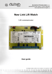
1
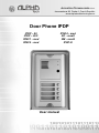
ALPHATECH TECHNOLOGIES s.r.o.
Jeremenkova 88, Praha 4, Czech Republic
www.alphatechtechnologies.cz
Door Phone IPDP
IPDP – 00
IPDP – 00C
IPNC1 - mod
IPNC2 - mod
IPNC4 - mod
NC - mod4
NM - mod4
IPDP-K
User manual
Welcome
We congratulate you on purchase of “DoorPhone VoIP” (VoIP = Voice over
IP), which is the improved version of successful “New DoorPhone” (NUDV).
This DoorPhone VoIP will widely manage to satisfy your needs of
communication with persons at the building front door or your company entry,
or family house doorway. The universality lies in possibility to connect this
guard to an Ethernet network or VoIP exchange or directly to SIP server
through internet conection.
The basic DoorPhone VoIP module (IPDP-00) is supplied without button. The
next version of basic VoIP module (IPDP-00C) is with integrated colour
camera. The buttons modules are connected to basic module (IPDP-00 or
IPDP-00C) and they are manufactured with 1, 2 or 4 buttons with Ethernet
connection (IPNC1-mod, IPNC2-mod, IPNC4-mod). Further the whole system
allows to be enlarged by NC-mod4 and NM-mod4 modules up to 64 buttons
using the basic mechanical MK1...MK4 units. The whole assembly can be
completed with cover frame or rain-protective case for flash or surface
instalation.The last optional module is Keypad (IPDP-K).
The Doorphone is supplied from AC/DC powersupply 12V. The basic features
include the possibility to open up to two doors by means of connected electrical
locks (the first 10 buttons can be used for door code opening) and easier
programming by WEB sites from PC by network connection.
Table of Contents
DOORPHONE VOIP ................................................................................................... 1
1
BASIC DESCRIPTION....................................................................................... 4
1.1
FEATURES ...................................................................................................... 4
1.2
MODULE ASSEMBLY ...................................................................................... 5
1.3
MODULE FEATURES ....................................................................................... 6
1.3.1 IPDP Basic Module .................................................................................. 6
1.3.2 Extending Module IPNCx-mod, NC-mod4 and NM-mod4........................ 9
1.3.3 IPDP-K Keyboard Module .................................................................... 10
1.4
INSTALLATION OF DOORPHONE VOIP ASSEMBLY ....................................... 11
1.4.1 Installation on Plaster............................................................................. 11
1.4.2 Flush-Mounted Installation .................................................................... 11
1.5
CHANGE OF NAMEPLATES ............................................................................ 11
1.6
FOCUS CAMERA AND DESCRIPTION OF FRONT PANEL ................................... 13
2
DOORPHONE VOIP OPERATION ............................................................... 14
2.1
SIGNALING OVERVIEW................................................................................. 14
2.2
VISITOR AT DOOR ........................................................................................ 14
2.2.1 DoorPhone without Keyboard ................................................................ 14
2.2.2 DoorPhone with Keyboard ..................................................................... 15
2.3
PERSON INSIDE OBJECT ............................................................................... 16
2.3.1 Outgoing Call ......................................................................................... 16
2.3.2 Incoming Call ......................................................................................... 16
3
PROGRAMMING OF PARAMETERS.......................................................... 17
3.1
BASIC VOIP SETTINGS ................................................................................. 17
3.1.1 Choosing a mode and login .................................................................... 17
3.1.2 Language option ..................................................................................... 18
3.1.3 Network settings...................................................................................... 18
3.1.4 Peer to peer or SIP server connection .................................................... 20
3.1.5 Audio codec setting ................................................................................. 20
3.1.6 Setting video............................................................................................ 21
3.1.7 Service settings ....................................................................................... 22
3.2
SETTING DOORPHONE PARAMETERS ............................................................ 23
3.2.1 Basic Parameters .................................................................................... 23
3.2.2 All about relays....................................................................................... 24
3.2.3 Time Parameters..................................................................................... 26
3.2.4 Direct Dialing – Memories ..................................................................... 27
4
TECHNICAL PARAMETERS......................................................................... 28
4.1
4.2
ELECTRICAL PARAMETERS .......................................................................... 28
MECHANICAL DIMENSIONS .......................................................................... 28
IPDP - installation and operating instructions
3
1
Basic Description
1.1
Features
4
Modular system allows to connect 4 to 64 buttons
Voice communication is supplied only from telephone line
Two 16digit numbers (IP adress) with each button
Day/night switching
Possibility of the call extension by * or # choice
Possible to connect two independent locks for door opening
Possible use of 5 switch modes (e.g. camera, lighting, gradual
opening)
Two codes for hanging up the guard from telephone
Two codes for door opening from telephone
Six code locks (password from buttons at the door)
Possibility to connect a numerical keyboard this way that the guard
can include 4 – 18 standard buttons
Integrated heating of printed circuit
Permanent lighting through visiting cards
Included color camera
Ethernet – 10/100Mb with standard 10BaseT a 100BaseTx
Web server for remote configuration – BOA
Power supply 12V AC/DC, 500mA
Operating system – Linux 2.6
USB for connection camera – USB guest 1.1, software GSPCA
software for video transmission to the browsers in PC – W3CAM(JPEG, RTSP Streem)
SIP connection P2P or PBX network system
WEB – firmware upgradeable
WEB – interface for control and setup parameter
IPDP - installation and operating instructions
1.2
Module Assembly
The IPDP structural elements are the basic modules with color camera
IPDP-00C or without camera IPDP-00 and extending button modules
IPNC1-mod with one button, IPNC2-mod with two buttons, IPNC4-mod,
NC-mod4 and NM-mod4 with four buttons. Further it is possible to provide the
assembly with numerical keyboard. The complete assembly consists similarly
to IPDP system of max. 4 modules in column and max. 3 columns side by side.
IPDP-00
IPDP-00C
NC-mod4
NM-mod4
MK-2
Fixing
frame 2
IPNC1-mod
IPNC2-mod
IPNC4-mod
IPDP-K
Flanging frame2 Canopy2
(flush -mounted) protective cover
(flush-mounted)
KPD2-rain
(on plaster)
By flush-mounted assembly the MK-1 to MK-4 boxes are used as well as with
UDV system.
Examples of frame configuration
IPDP - installation and operating instructions
5
1.3 Module Features
1.3.1 IPDP Basic Module
The IPDP basic module assembling from modulus IP and
motherboard. Positioning setting elements and connectors is on picture 1.
Picture 1 Basic module - motherboard
The “14 pin black conector” serves the connection of extending modules by
means of flat cable.
The “USB” serves the connection internal color camera
6
IPDP - installation and operating instructions
For IPDP is necessary used the AC voltage of min. 10Vst - max. 15Vst or DC
voltage of min. 12Vss to max. 18Vss must be energized to “12V” terminal. This
source loading depends on number of modules, since it simultaneously serves
feeding of lighting through visiting cards – at max. number of connected
modules the demand will not exceed 300mA. This source can be also used for
feeding of lock(s), and then it is necessary to consider the electrical lock
demand. In practice the alternating feeder 12V/1A mostly meets these
demands.
The connection of relay contact terminals is shown on fig. 1. The “NO”
designation means an idle-disconnected contact, “COM” means a pin contact
(middle) and “NC” means an idle-connected contact. The contacts of both
switches are galvanically isolated each other and from other guard circuits. The
variants of connection are shown on picture. 2.
Picture 2 Examples of relays connections
IPDP - installation and operating instructions
7
Setting voice communication –
position trimmers are presetting from
manufacture and in majority case
agree with, therefore changes setting
altering only in necessary case. Basic
position of trimmers, sense of rotation
and meaning trimmers are illustration
on picture 3.
Picture 3 Setting of trimmers
DIP switch setting basic operation and default
setting. See on picture 4.
Picture 4 DIP switch settings
8
IPDP - installation and operating instructions
1.3.2
Extending Module IPNCx-mod, NC-mod4 and NM-mod4
This module is supplied in three designs. The IPNCx-mod module
(picture 6) has four buttons and includes the electronics to be connected to the
basic module. The NC-mod4 module has four buttons and includes the
electronics to be connected to the IPNCx-mod or to previous NC-mod4 module.
This module is only connected by flat cable – buttons and lighting through is
already interconnected. The terminals for connection of other four buttons and
current supply of lighting are further placed on module (on following NM-mod4).
The NM-mod4 module is always connected to previous IPNCx-mod or
NC-mod4. The connection is not prepared and should be done by conductors –
see on picture 5.
Picture 5 Connection of (IP)NC-mod4 and NM-mod4
IPDP - installation and operating instructions
9
The flat cable connection is facilitated by connector
locks, preventing from rotation, but to keep the
connection routing is imperative.
“To IP DoorPhone” is always the routing to the basic
module.
“To NCmod” is
routing to the row
end (on last
NC-mod.).
Picture 6 IPNC4-mod module
1.3.3
IPDP-K Keyboard Module
The keyboard module is only connected by flat cable as
well as NC-mod4 module. The only difference is that
keyboard module is always the last in row (no other
module can be connected behind it). Connect on the first place (to output of the
IPNCx-mod) or the second (to output of the first NC-mod4) positions or third
place. It means that 4 to 24 buttons with direct dialing can be used instead of
keyboard (per assembly). The most frequent used assemblies are:
IPDP-00 + IPNCx-mod + IPDP-K
IPDP-00 + IPNCx-mod + NM-mod4 + IPDP-K
IPDP-00 + IPNCx-mod + NM-mod4 + NC-mo4 + IPDP-K
IPDP-00 + IPNCx-mod + NM-mod4 + NC-mod4 + NM-mod4 + IPDP-K
Pay attention when programming – the position of keyboard connected must be
correctly specified.
The choice is entered by gradual
pressing of buttons with digits. Firstly
the key symbol must be pressed to
enter a password. When pressing X,
the DoorPhone will hang up or cancel
your dial. Button with key symbol use
for “Point” in IP adress in P2P mode.
10 IPDP - installation and operating instructions
1.4 Installation of DoorPhone VoIP Assembly
1.4.1
Installation on Plaster
By installation on plaster the only compact box
- Rain-Protective Cover KPDxx is used, which
will supersede all mechanical parts (MKxx,
Canopy xx and Fixing Frame xx). The
installation is made by screwing to the wall by
means of dowels. See KPD1 on figure.
1.4.2
Flush-Mounted Installation
The MKxx mounting box is built-in wall. Be
careful in orientation of assembling holes
when nearly MK1 square box is used – it
must be in vertical axis. The well-embedded box is
shown on figure.
The Protecting Frame (provides overlapping of
unevenness after mounting box walling-in) and
Canopy (necessary for installation in external
areas) form other accessories for flush-mounted installation. When installed in
surroundings with possible water condensation (temperature changes) or water
spraying (rain) it is recommended to connect the jumper on basic module –
heating ON.
The board heating has two positive functions partly it heats up the electronics
in winter at temperatures below –20°C (most details with extended temperature
range has guaranteed parameters from –20°C) and par tly with external
installation at swift temperature changes and higher air humidity by switched
heating no water condensation occurs on basic guard board, which assures its
reliable function.
1.5 Change of nameplates
The first step is dismantling of a
fixing frame from module, where we
want to change a nameplate. It can
be executed by unscrewing of two
screws under plastic covers on fixing
frame. When removing the fixing
frame we can see two independent
modules. The front part (metallic) of
the button module has to be first separated from plastic part in this way that we
will put off the plastic lug, ensuring the front part on the right side. Each button
has its separate nameplate hold by means of plastic flag (see figure). The
paper nameplates can be printed from Excel form (to be downloaded on
www.alphatech.cz).
IPDP - installation and operating instructions
11
Picture 7 Mechanical assembly parts
12 IPDP - installation and operating instructions
1.6 Focus camera and description of front panel
If is need focus picture from camera, so everything is illustration on picture
front panel basic module on Picture 8 .
Picture 8 front panel of basic module IPDP
1. front panel
2. microphone
3. indication LED
4. turning with objective of camera is focus picture
5. camera
6. press on this tongue in direction arrow is unfix front panel
IPDP - installation and operating instructions
13
2 DoorPhone VoIP Operation
2.1 Signaling Overview
The all-purpose guard signals an acoustic conditions they may occur during
operation. Another signaling can be done by means of red LED (placed under
microphone hole). You can listen the signaling samples in Nset setting
program.
Condition
Tones
Tone frequency
LED
Line lifting up
–▄–■–▀–
425-850-1275
glows
Line hanging up
–▀–■–▄
1275-850-425
goes
out
Report after calling
–▄–■–▀–
425-850-1275
glows
Notice about call end
–■–■–■–
1275
glows
Parameter confirmation
Switch on (Reset)
––█––
glows
–■–▄–■–
1275-850-1275
Error (anything, if unsuitable)
–■–■–■–■–■–■–
425….
Empty memory (no progr. numb.)
–█–▄–■–▄–■–▄–
850-1275-1700…
blinks
2.2 Visitor at Door
The all-purpose guard function is influenced partly by used guard assembly
(with keyboard or without it) and partly by setting of guard parameters.
2.2.1
DoorPhone without Keyboard
The DoorPhone buttons are provided by nameplates or positions of persons
inside the object. The incoming person will press the corresponding button, the
DoorPhone will lift up the VoIP canale neither immediately (the button is not the
first number from code lock), or with delay and dial the programmed phone
number thru VoIP, but dial number differs by choice mode, which is set in the
DoorPhone :
- Day/night mode = being the DoorPhone in Day mode, so it is always
dialing a number set in table 1, in Night mode, it is always dialing a
number set in table 2.
- mode two number group = first press – it always dials a number set
in table 1. By repeated press of the same button or detection of busy
tone after dialing the DoorPhone will select the number from the
second group (table 2). The next press of the same button again
selects a number of the first group, etc..……
The switch (code lock) can be controlled by first 10 buttons of DoorPhone. If
the visitor at door presses buttons in such combination that meet the
14 IPDP - installation and operating instructions
preprogrammed code and the time among presses is not bigger than the set
point, then the DoorPhone will pick up and close the corresponding switch (if
set in m=1 or m=5 modes) to the period given by seting in parameters. Then it
will hang up.
2.2.2
DoorPhone with Keyboard
The DoorPhone with keyboard can also include
besides the keyboard up to 16 buttons of direct
dialing always behaving as to be mentioned in
chapter 1.3.3 (page 10) except the code lock. This
one is always situated on keyboard. After keyboard
is connected, the position, where the keyboard is
connected to, should be set in programming
parameter.
The keyboard has two functional buttons – key
symbol = once pressing the numerical combination is considered as the
combination for control of the switches. The second button –X symbol = when
pressing the DoorPhone immediately will hang up.
The number selection on keyboard can be executed in two ways:
- The incoming person is dialing number as to be done on phone – the
period among button presses should be lower than the value given
by programming parameter. After this period the DoorPhone will lift
up and dial the given number.
- On buttons the incoming person is dialing a two-digit number (from
01 to 64), which represents the memory number, where the 16-digit
number is stored (same as for buttons). The number dialing is
managed by Day/Night setting or mode for two groups of numbers
(as described in chapter 2.2.1 page 14).
IPDP - installation and operating instructions
15
2.3 Person Inside Object
The person inside object is considered a person that is in phone contact with
DoorPhone.
2.3.1
Outgoing Call
The outgoing call is the call from DoorPhone (caused by visitor). After guard
choice the telephone is ringing inside object and the pickuping up will allow
speaking to the visitor at door. The code choice can close the switch, if set to
m=1 or m=5 modes, change over the Day/Night modes and hang up the
DoorPhone. The DoorPhone in 10 seconds before call end will send a notice
about call end and the call may be extended by sign selection (* or #). The
telephone hanging up will end the call.
2.3.2
Incoming Call
The incoming call is the call to the DoorPhone (caused by person inside
object). After exchange number selection, where the DoorPhone is connected,
the DoorPhone is ringing and when set number of rings is over, the DoorPhone
will pick up and it is possible to speak. The possibilities are the same as with
outgoing call.
16 IPDP - installation and operating instructions
3 Programming of Parameters
3.1 Basic VoIP settings
3.1.1
Choosing a mode and login
It is important to choose a DoorPhone mode first. The
DoorPhone can work in the PeerToPeer mode or SIP
server mode. The mode setting can be made by a
relevant switch (DIP switch see on picture 8). In the SIP
server mode is possible to choose SIP server (external).
It can be set in a configuration interface of the
DoorPhone.
Picture 9 DIP switch setting
In your web browser enter IP address of the DoorPhone, default is
192.168.1.250. See Picture 10. Enter user name and password. User name is
„admin“, default password is „1234“. See Picture 10.
Picture 10 First site - video from camera
Picture 11 Login to setup
IPDP - installation and operating instructions
17
3.1.2
Language option
Language setting can be made in a menu on the left panel.
3.1.3
Network settings
Network settings are located in the Network seting menu item. It is possible to
use DHCP service (1) or you can enter IP addresses manually.
Manual configuration:
After making changes click on a save and restart button.
1 – Enable/disable ethernet settings via DHCP
2 – Default value – presetings to the firm settings. After making changes click
on a save and restart button (display screen - see page 22).
18 IPDP - installation and operating instructions
DHCP configuration:
After making changes click on a save and restart button.
1 – Enable/disable ethernet settings via DHCP
2 – show automatic DHCP generate IP adress and othet settings
3 – Default value – presetings to the firm settings. After making changes click
on a save and restart button (display screen - see page 22).
4 – Show mode of DoorPhone – Day/Night
5 – Return to the video from color camera screen
Important: if you use setup via DHCP, then it‘s assigning IP address to
DoorPhone automatically and network administrator must tell you actual
address, to was possibility display video in web browser. Because assigning IP
adress can change after e.g . failure power supply in object, so they
recommended enjoy DoorPhone with fixed IP address.
IPDP - installation and operating instructions
19
3.1.4
Peer to peer or SIP server connection
The DoorPhone can be set to the peer to peer (P2P) mode or to the SIP server
mode by DIP switch (page 17). In P2P mode DoorPhone calling IP adress – in
memory buttons (page 27).
If you setting SIP server mode by DIP switch, so add in menu item SIP
parameters
After making changes use the save changes button.
1 – SIP proxy server IP adress or the SIP server name and port (usually 5060
or 5061)
2 – Registering data to SIP proxy server
3 – Default value – presetings to the firm settings. After making changes use
the save changes button.
3.1.5
Audio codec setting
After making changes use the save changes button.
1 – There is choosing only priority using audio codecs, used codec is selection
automatically at make audio connection in SIP protocol.
2 – Default value – presetings to the firm settings. After making changes use
the save changes button.
20 IPDP - installation and operating instructions
3.1.6
Setting video
After making changes use the save changes button.
1 – Resolution display video
2 – Number picture per second (frequency restoring picture)
3 – Setting next parameters of camera
4 – Default value – presetings to the firm settings. After making changes use
the save changes button.
IPDP - installation and operating instructions
21
3.1.7
Service settings
1 – display current version of firmware in module VoIP and in module
doorphone, button switching if is has save history events in basic or
enhanced mode - it is important to analyses mistakes and problems. This
file it is possible save to PC by click on download log file.
2 – tool for upgrade firmware in module VoIP and in module doorphone,
switching automatic - information is in upload fille. Firmware upgrade use for
file with new style designed too – color,fonts, logo (picture max 200pxl)
3 – Addition / change language file - upload fille with language assignment
4 – change access password, default is 1234
5 – reboot VoIP module.
22 IPDP - installation and operating instructions
3.2 Setting DoorPhone parameters
3.2.1
Basic Parameters
After making changes use the save changes button.
1 – Mode of DoorPhone choice selects number per Day/Night DoorPhone
mode or selects numbers of the first and second groups.
2 – Sign for call extension * or # (10sec before call end the DoorPhone will send
a notice, then the call may be extended)
3 – Two commands in order to hang up the DoorPhone using both switches
[2 digits].The advantage is to set the same command both for switch closing
and command to guard hanging up (page 24).
4 – Command for DAY / NIGHT mode switching
Note: The switchover to Day/Night mode remains set in guard even after
power supply disconnection.
5 – Dialing as on normal telephone (all number of called person should be
pressed on keyboard) - recommended for use SIP proxy server.
Only 2-digit memory number is entered on keyboard by which the number of
called person is stored (memory number corresponds to button number with
respect to Day/Night switchover) - recommended for use P2P.
6 – =0 only NC-mode connected to the basic module
=1 the keyboard connected on the first position (after IPNCx-mod)
=2 the keyboard connected on the second position (after first NC-mod4)
=3 the keyboard connected on the third position (after second NC-mod4)
explanation of position keyboard is on chapter 1.3.2 (page 9)
7 – Default value – presetings to the firm settings. After making changes use
the save changes button.
ATTENTION! This parameters setting will sharply influence whole DoorPhone
function.
IPDP - installation and operating instructions
23
3.2.2
All about relays
After making changes use the save changes button.
1 – Relay mode:
=1 switch mode – it will close on command or password for period t1/2
(used for electrical locks, gate opening etc.)
=2 camera mode – it will close by guard pick up and open by hanging up.
=3 lighting mode – it will close by guard pick up and stay closed even for
period t1/2 after guard hanging up.
=4 bell mode – it will close after button pressing and open after period t1/2
(used for e.g. external bell or horn connections).
=5 gradual opening mode – in this mode the only relay 2 will be set
together with relay 1 set to mode 1. The relay 1 is activated for period t1,
then the time t3 is proceeding before relay 2 closing. Then the relay 2 is
activated for t2 period and afterwards the DoorPhone hangs up.
Note: The only relay 1 can be activated from phone and all sequence started.
Besides that the relay 2 can be separately activated from buttons by password.
24 IPDP - installation and operating instructions
2 – password for relay closing from buttons or keyboard [2 to 6 digits]. Total 6
passwords, they are controlled by Day/Night; the combination is entered
either by DoorPhone buttons (first 10 buttons) or from attached keyboard
(after pressing of key symbol). The relay closing influences the set switch
mode and Day/Night switchover. By setting of choice mode of 2 number
groups the DoorPhone is permanently in DAY mode.
By password choice some rules have to be observed:
Select passwords in way not to find its combination out from
wear of certain buttons by frequent use.
Select the first password button from frequentless button for
direct dialing (-extends choice time)(-not valid for keyboard).
Pay attention to congruity of password numbers when one
password includes other one, e.g. relay 1 has 1234 and relay 2
has 12345. Then after pressing button 4 the only relay 1 is
called, but password choice 234 for relay 2 can call both relays
after pressing switch 4.
3 – Command from phone after relay closing [2 digits]. The same command can
be set for both relays, then they are activated at the same time. The
advantage is to set the same command both for relay closing and command
to DoorPhone hanging up (page 23).
4 – Duration of relay closing in second [2 digits 01-99]
5 – To prohibit the control during incoming call is important e.g. when using
relay 2 in mode 1 for control of garage gate opening, when the electronics
opens the gate and the gate is closed by car passage. Then the control from
phone could undesirably cause the permanent gate opening (not closed –
no car passage).
6 – time in second between close relays 1 and 2 by mode setting of relay 2 is 5
(gradual opening) [2 digits 01-99]
7 – Default value – presetings to the firm settings. After making changes use
the save changes button.
IPDP - installation and operating instructions
25
3.2.3
Time Parameters
After making changes use the save changes button.
1 – max. time, for which the DoorPhone is hanging up, this time can be
extended during call by sign choice from telephone (* or #) – see page 23.
2 – Number of incoming call rings, the DoorPhone pick up after preseted
number of rings. After detection first ring – LED on front panel blinking. The
number can be set from 1 to 9.
3 – max. time [sec] among button presses [range 1-9]
normal buttons
- switch closing – if time between two next presses is bigger than w
time, the code is not evaluated correctly.
- dialing – if the button, we are pressing, is the first password number
for switch closing, so the choice is delayed by this w time.
keyboard
- switch closing – if time between two next presses is bigger than w
time, the code is not evaluated correctly.
dialing the same as of phone, if time after the last pressed button
is bigger than w time, then the dialing starts. If the number is
incomplete, it is necessary to hang up (X button) and the
dialing will be repeated.
dialing from memory, if time following the first pressed button is
longer than w time, then the entry of memory number has to
be repeated.
4 – time [sec] for which the guard will hang up, before repeated dialing (button
pressing during call or dialing, busy tone detection) [range 1-5]
5 – after finishing the dialing it calculates time (ringing tones). If the number
exceeds time in second, it will hang up [range 10-99]. The dialing is
repeated in case, when the dialing mode of 2 groups is set.
6 – In default is status of DoorPhone signalling acoustically. If signalling makes
problem, so this signalling pick up / hang up prohibited.
26 IPDP - installation and operating instructions
7 – In default is status of DoorPhone signalling acoustically. If signalling makes
problem, so this signalling others tones prohibited.
8 – Default value – presetings to the firm settings. After making changes use
the save changes button.
3.2.4
Direct Dialing – Memories
After making changes use the save changes button.
1 – telephone number up to 16 digits, we want to store. The numbers are the
numbers of the first group or numbers of Day mode. In default setting is
table memoirs empty. While using setting P2P to the memoirs saves IP
address e.g . 192*168*1*250, where „*“ means „.“ , while using SIP proxy
server to the memoirs saves phone number e.g. 117.
2 – telephone number up to 16 digits, we want to store. The numbers are the
numbers of the second group or numbers of Night mode. In default setting
is table memoirs empty. While using setting P2P to the memoirs saves IP
address e.g . 192*168*1*250, where „*“ means „.“ , while using SIP proxy
server to the memoirs saves phone number e.g . 117.
Note: The switchover to Day/Night mode remains set in DoorPhone even
after power supply disconnection.
3 – Default value – presetings to the firm settings. After making changes use
the save changes button.
IPDP - installation and operating instructions
27
4 Technical Parameters
4.1 Electrical Parameters
Parameter
Value
Communication interface
VoIP protocol supported
Band width
Power supply of lighting through,
switches and heating
Max. consumption
Max. voltage of switch contact
Max. current of switch contact
Operational temperature
Conditions
Ethernet 10BaseT, 100BaseTx
SIP
300Hz – 3400 Hz
12Vss ± 2V , 10-12Vst ± 2V
300mA
48V
2A
12Vss
at I < 1A
at U < 30 V
- 20 to + 50°C
4.2 Mechanical dimensions
Type of item
MKxx mount. box
KPDxx (on plast.)1col.
KPDxx (on plast.)2col.
Canopy xx
Fixing frame
dimensions HxWxD [mm]
1 module 2 modules 3 modules 4 modules
114x118x45
151x157x79
149x151x49
147x151x3
28 IPDP - installation and operating instructions
204x118x45
241x157x79
241x286x79
241x151x49
239x151x3
294x118x45
331x157x79
331x151x49
299x151x3
384x118x45
421x157x79
421x286x79
421x151x49
399x151x3
Guarantee conditions:
The product was shop-checked. The producer guarantees that this product will
keep the features described in these operating instructions in the course of
guarantee provided that the user will be handled with it as described in the
operating manual. The guarantee will be extended by period of possible
guarantee repair.
When claiming in guarantee period please contact your dealer. The producer
only will make the guarantee repairs. Attach the description of claim reason,
proof of purchase and your exact address to the product.
The guarantee does not include:
• mechanical, thermal, chemical and other damages caused by user’s
activities
• defects caused by natural disasters
• defects caused by repair or changes carried out by user or other
unauthorized person
• willful damage of product
• incorrect use of product caused by other use than specified in
operating manual (e.g. installation, programming)
• damages caused during product transport to customer and from
supplier
Producer:
Dealer:
Date of sale:
© JR 2008 version V1.0 IX/08
ALPHATECH TECHNOLOGIES s.r.o.
Jeremenkova 88, Praha 4, Czech Republic
www.alphatechtechnologies.cz
ALPHATECH TECHNOLOGIES s.r.o.
Jeremenkova 88
140 00 Praha 4
Czech Republic
VAT: CZ27577350
Company is registered in the Commercial Register
administered by the Municipal
Court in Prague, Section C, Record 116886
Banking details:
Komerční banka, account No. 43-7671450207/0100
IBAN: CZ0801000000437671450207
SWIFT: KOMBCZPPXXX