1
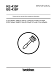
BAS-311H
INSTRUCTION MANUAL
Please read this manual before using the machine.
Please keep this manual within easy reach for quick reference.
DIRECT DRIVE
PROGRAMMABLE ELECTRONIC PATTERN SEWER
Thank you very much for buying a BROTHER sewing machine. Before using your new machine,
please read the safety instructions below and the explanations given in the instruction manual.
With industrial sewing machines, it is normal to carry out work while positioned directly in front of
moving parts such as the needle and thread take-up lever, and consequently there is always a
danger of injury that can be caused by these parts. Follow the instructions from training personnel
and instructors regarding safe and correct operation before operating the machine so that you will
know how to use it correctly.
BAS-311H
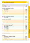
CONTENTS
1. NAMES OF MAJOR PARTS ................ 1
2. SPECIFICATIONS ................................ 2
3. INSTALLATION .................................... 3
3-1. Table processing diagram ................................ 4
3-2. Installing the control box ................................... 5
3-3. Installing the oil pan .......................................... 5
3-4. Installing the machine head .............................. 6
3-5. Installing the operation panel ........................... 9
3-6. Installing the two-pedal foot switch ................. 10
3-7. Connecting the cords ........................................ 10
3-8. Connecting the ground wire.............................. 13
3-9. Connecting the power cord............................... 14
3-10. Installing the cotton stand ............................... 17
3-11. Installing the pneumatic unit
(pneumatic work clamp specifications) ............. 18
3-12. Installing the eye guard .................................. 19
3-13. Installing the side cover and rear cover.......... 19
3-14. Lubrication ...................................................... 20
3-15. Installing the machine head fixing bolt ........... 21
3-16. Installing the bobbin winder tension ............... 21
3-17. Checking the machine head switch ................ 21
4. PREPARATION BEFORE SEWING ..... 22
4-1. Installing the needle .......................................... 22
4-2. Threading the upper thread .............................. 22
4-3. Winding the lower thread .................................. 24
4-4. Installing the bobbin case ................................. 25
4-5. Thread tension .................................................. 26
4-5-1. Lower thread tension ........................... 26
4-5-2. Upper thread tension ........................... 26
4-6. Starting up ........................................................ 27
5. USING THE OPERATION PANEL
(BASIC OPERATIONS) ....................... 28
5-1. Name and function of each operation
panel item ......................................................... 28
5-2. Program setting method .................................... 30
5-2-1. Parameter list ....................................... 31
5-2-2. Using the lower thread counter ............ 33
5-2-3. Using the production counter ............... 34
5-2-4. Split number setting method ................ 35
5-3. Copying programs ............................................. 36
5-4. Checking the sewing pattern............................. 37
5-5. Setting the work clamp lift amount .................... 38
6. USING THE OPERATION PANEL
(ADVANCED OPERATIONS) .............. 40
6-1. Setting memory switches .................................. 40
6-2. List of memory switch settings .......................... 41
6-3. Using cycle programs ....................................... 43
6-4. Direct selection.................................................. 46
6-5. Resetting all settings to their defaults ............... 47
7. USING SD CARDS ............................... 48
7-1. Notes on handling SD cards
(commercially available) ................................... 48
7-2. Structure of an SD card folder .......................... 48
7-3. Preparation for reading and writing data ........... 49
7-4. Reading additional sewing data ........................ 50
BAS-311H
8. SEWING................................................ 51
11. LIST OF ERROR CODES ................... 68
8-1. Sewing .............................................................. 51
8-2. Using the STOP switch..................................... 52
12. TROUBLESHOOTING ........................ 75
9. CLEANING ........................................... 53
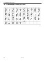
13. 7-SEGMENT DISPLAY LIST .............. 79
9-1. Cleaning the rotary hook .................................. 53
9-2. Cleaning the control box air inlet ports ............. 54
9-3. Draining the oil .................................................. 54
9-4. Cleaning the eye guard .................................... 54
9-5. Checking the needle ......................................... 54
9-6. Lubrication ........................................................ 54
10. STANDARD ADJUSTMENTS ............ 55
10-1. Checking the machine head switch ................ 55
10-2. Thread take-up spring .................................... 56
10-3. Arm thread guide R ........................................ 56
10-4. Adjusting the needle bar height ...................... 57
10-5. Adjusting the needle bar lift amount and the
driver needle guard ......................................... 57
10-6. Adjusting the needle clearance ...................... 58
10-7. Adjusting the shuttle race thread guide .......... 58
10-8. Rotary hook lubrication amount ...................... 58
10-9. Adjusting the position of the movable knife .... 59
10-10. Replacing the movable and fixed knives ...... 61
10-11. Installing the feed plate................................. 62
10-12. Adjusting the thread wiper ............................ 63
10-13. Presser foot installation position ................... 63
10-14. Changing the intermittent stroke .................. 64
10-15. Adjusting the work clamp lift amount ............ 66
10-16. Adjusting the air pressure
(pneumatic work clamp specifications) ........ 66
10-17. If processing the work clamps and the feed
plate to a shape that matches the sewing
pattern .......................................................... 67
BAS-311H
SAFETY INSTRUCTIONS
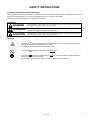
[1] Safety indications and their meanings
This instruction manual and the indications and symbols that are used on the machine itself are provided in order to ensure
safe operation of this machine and to prevent accidents and injury to yourself or other people.
The meanings of these indications and symbols are given below.
Indications
DANGER
The instructions which follow this term indicate situations where failure to follow the
instructions will result in death or serious injury.
WARNING
The instructions which follow this term indicate situations where failure to follow the
instructions could result in death or serious injury.
CAUTION
The instructions which follow this term indicate situations where failure to follow the
instructions may result in minor or moderate injury.
Symbols
・・・・・・
This symbol ( ) indicates something that you should be careful of. The picture inside the triangle
indicates the nature of the caution that must be taken.
(For example, the symbol at left means “beware of injury”.)
・・・・・・
This symbol (
・・・・・・
This symbol ( ) indicates something that you must do. The picture inside the circle indicates the
nature of the thing that must be done.
(For example, the symbol at left means “you must make the ground connection”.)
) indicates something that you must not do.
BAS-311H
i
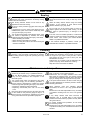
[2] Notes on safety
DANGER
Wait at least 5 minutes after turning off the power switch and disconnecting the power cord from the wall outlet
before opening the control box cover. Touching areas where high voltages are present can result in severe injury.
WARNING
Do not allow any liquids to get onto this sewing machine, otherwise fire, electric shocks or operating problems may
occur.
If any liquid gets inside the sewing machine (machine head or control box), immediately turn off the power and
disconnect the power plug from the electrical outlet, and then contact the place of purchase or a qualified
technician.
CAUTION
Environmental requirements
Use the sewing machine in an area which is free from
sources of strong electrical noise such as electrical
line noise or static electric noise.
Sources of strong electrical noise may cause
problems with correct operation.
Any fluctuations in the power supply voltage should
be within ±10% of the rated voltage for the machine.
Voltage fluctuations which are greater than this may
cause problems with correct operation.
The power supply capacity should be greater than the
requirements for the sewing machine's power
consumption.
Insufficient power supply capacity may cause
problems with correct operation.
The pneumatic delivery capability should be greater
than the requirements for the sewing machine's total
air consumption.
Insufficient pneumatic delivery capability may cause
problems with correct operation.
The ambient temperature should be within the range
of 5°C to 35°C during use.
Temperatures which are lower or higher than this
may cause problems with correct operation.
The relative humidity should be within the range of
45% to 85% during use, and no dew formation should
occur in any devices.
Excessively dry or humid environments and dew
formation may cause problems with correct operation.
In the event of an electrical storm, turn off the power
and disconnect the power cord from the wall outlet.
Lightning may cause problems with correct operation.
Installation
Machine installation should only be carried out by a
qualified technician.
Contact your Brother dealer or a qualified electrician
for any electrical work that may need to be done.
The sewing machine weighs approximately 88 kg.
The installation should be carried out by two or more
people.
Do not connect the power cord until installation is
complete. If the foot switch is depressed by mistake,
the sewing machine might start operating and injury
could result.
Hold the machine head with both hands when tilting it
back or returning it to its original position.
Furthermore, do not apply excessive force when
tilting back the machine head. The sewing machine
may become unbalanced and fall down, and serious
injury or damage to the sewing machine may result.
Be sure to connect the ground. If the ground
connection is not secure, you run a high risk of
receiving a serious electric shock, and problems with
correct operation may also occur.
ii
BAS-311H
All cords should be secured at least 25 mm away
from any moving parts. Furthermore, do not
excessively bend the cords or secure them too firmly
with staples, otherwise there is the danger that fire or
electric shocks could occur.
Install the safety covers to the machine head and
motor.
If using a work table which has casters, the casters
should be secured in such a way so that they cannot
move.
Be sure to wear protective goggles and gloves when
handling the lubricating oil and grease, so that they
do not get into your eyes or onto your skin. If the oil
and grease get into your eyes or onto your skin,
inflammation can result.
Furthermore, do not drink or eat the lubricating oil or
grease. They may cause diarrhea or vomiting.
Keep the oil out of the reach of children.
CAUTION
Sewing
This sewing machine should only be used by
operators who have received the necessary training
in safe use beforehand.
If using a work table which has casters, the casters
should be secured in such a way so that they cannot
move.
The sewing machine should not be used for any
applications other than sewing.
Attach all safety devices before using the sewing
machine. If the machine is used without these
devices attached, injury may result.
Be sure to wear protective goggles when using the
machine.
If goggles are not worn, there is the danger that if a
needle breaks, parts of the broken needle may enter
your eyes and injury may result.
Turn off the power switch at the following times. If the
foot switch is depressed by mistake, the sewing
machine might start operating and injury could result.
• When threading the needle
• When replacing the bobbin and needle
• When not using the machine and when leaving the
machine unattended
Do not touch any of the moving parts or press any
objects against the machine while sewing, as this
may result in personal injury or damage to the
machine.
If an error occurs in machine operation, or if abnormal
noises or smells are noticed, immediately turn off the
power switch. Then contact your nearest Brother
dealer or a qualified technician.
If the machine develops a problem, contact your
nearest Brother dealer or a qualified technician.
Cleaning
Turn off the power switch before carrying out
cleaning. If the foot switch is depressed by mistake,
the sewing machine might start operating and injury
could result.
Be sure to wear protective goggles and gloves when
handling the lubricating oil and grease, so that they
do not get into your eyes or onto your skin. If the oil
and grease get into your eyes or onto your skin,
inflammation can result.
Furthermore, do not drink or eat the lubricating oil or
grease. They may cause diarrhea or vomiting.
Keep the oil out of the reach of children.
Maintenance and inspection
Maintenance and inspection of the sewing machine
should only be carried out by a qualified technician.
Ask your Brother dealer or a qualified electrician to
carry out any maintenance and inspection of the
electrical system.
Turn off the power switch and disconnect the power
cord before carrying out the following operations. If
the foot switch is depressed by mistake, the sewing
machine might start operating and injury could result.
• Inspection, adjustment and maintenance
• Replacing consumable parts such as the rotary
hook
Disconnect the air hoses from the air supply and wait
for the needle on the pressure gauge to drop to “0”
before carrying out inspection, adjustment and repair
of any parts which use the pneumatic equipment.
Hold the machine head with both hands when tilting it
back or returning it to its original position.
Furthermore, do not apply excessive force when
tilting back the machine head. The sewing machine
may become unbalanced and fall down, and serious
injury or damage to the sewing machine may result.
If the power switch needs to be left on when carrying
out some adjustment, be extremely careful to observe
all safety precautions.
When replacing parts and installing optional
accessories, be sure to use only genuine Brother
parts.
Brother will not be held responsible for any accidents
or problems resulting from the use of non-genuine
parts.
If any safety devices have been removed, be
absolutely sure to re-install them to their original
positions and check that they operate correctly before
using the machine.
To prevent accidents and problems, do not modify
the machine yourself.
Brother will not be held responsible for any accidents
or problems resulting from modifications made to the
machine.
BAS-311H
iii
[3] Warning labels
The following warning labels appear on the sewing machine.
Please follow the instructions on the labels at all times when using the machine. If the labels have been removed or are
difficult to read, please contact your nearest Brother dealer.
1
2
.
*Safety devices
Devices such as eye guard, finger guard, thread take-up cover,
side cover, rear cover, tension release solenoid cover, inner
cover, outer cover, fixed cover and gas spring support cover
3
Be careful not to get your hand caught when tilting back the machine head and returning it to its
original position.
4
Be sure to connect the ground. If the ground connection is not secure, you run a high risk of receiving
a serious electric shock, and problems with correct operation may also occur.
5
Direction of operation
6
Be careful to avoid injury from moving parts.
7
iv
Do not hold, otherwise problems with operation or injury may occur.
BAS-311H
Rear cover
Tension release solenoid cover
Inner cover L
Outer cover
Fixed cover
Side cover
Thread take-up cover
Inner cover R
Eye guard
Outer cover
Fixed cover
Finger guard
Gas spring support cover
3028B
3029B
BAS-311H
v
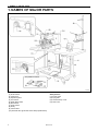
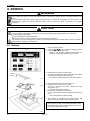
1. NAMES OF MAJOR PARTS
1. NAMES OF MAJOR PARTS
Two-pedal foot switch
3030B
(1) Power switch
(2) Control box
(3) Operation panel
(4) Foot switch
(5) Work clamp switch
(6) Start switch
(7) STOP switch
(8) Pulley
(9) Cotton stand
(10) Solenoid valve (pneumatic work clamp specifications)
1
Safety devices:
(11) Finger guard
(12) Eye guard
(13) Thread take-up cover
(14) Rear cover
BAS-311H
2. SPECIFICATIONS
2. SPECIFICATIONS
3190B
Sewing machine
Lock stitch pattern tacking sewing machine (with large shuttle hook)
Stitch formation
Single needle lock stitch
Max. sewing speed
2,800 sti/min
Max. sewing area (XxY)
Feed mechanism
150 x 100 mm
Intermittent feed, pulse motor drive
0.05 − 12.7 mm
Stitch length
No. of stitches
Maximum no. of stitches
No. of sewing data items
that can be stored
Work clamp lift method
Work clamp height
2-step work clamp
500,000-stitch internal memory (*1)
20,000 stitches (per program)
Internal memory: 512 (*1), SD card: 900
Motor-driven work clamp specifications: Pulse motor drive method
Pneumatic work clamp specifications: Pneumatic method
Motor-driven work clamp specifications: Max. 25 mm
Pneumatic work clamp specifications: Max. 30 mm
Motor-driven work clamp specifications: Integrated-type work clamp
Pneumatic work clamp specifications: Separate-type work clamp
Intermittent presser foot lift
amount
Intermittent stroke
Hook
22 mm
2 − 4.5 mm, 4.5 − 10 mm or 0 (Default setting 3 mm)
Double-capacity shuttle hook (standard shuttle hook sold separately)
Wiper device
Standard equipment
Thread trimmer
Standard equipment
Data storage method
Internal memory (Flash memory), SD card (*2)
User programs
900
Cycle programs
30
Motor
Weights
Power source
550 W
AC servo motor
Machine head approx. 88 kg, operation panel approx. 0.4 kg
Control box 9 kg (Differs depending on destination)
Single-phase 100V / 220V, 3-phase 220V / 380V / 400V
(For single-phase 100 V and three-phase 380 V/400 V, the trans box is required.)
Air pressure
0.5 MPa 1.8 l/min.
(*1)
The number of data items and stitches that can be stored will vary depending on the number of stitches in each
program.
(*2) No guarantees of operation can be given for any media.
BAS-311H
2
3. INSTALLATION
3. INSTALLATION
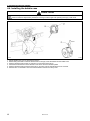
CAUTION
Machine installation should only be carried out by a
qualified technician.
Contact your Brother dealer or a qualified electrician
for any electrical work that may need to be done.
The sewing machine head weighs approximately
88kg. The installation should be carried out by two or
more people.
Do not connect the power cord until installation is
complete.
If the foot switch is depressed by mistake, the sewing
machine might start operating and injury could result.
Hold the machine head with both hands when tilting it
back or returning it to its original position.
Furthermore, do not apply excessive force when tilting
back the machine head. The sewing machine may
become unbalanced and fall down, and serious injury
or damage to the sewing machine may result.
3
BAS-311H
All cords should be secured at least 25 mm away from
any moving parts. Furthermore, do not excessively
bend the cords or secure them too firmly staples,
otherwise there is the danger that fire or electric
shocks could occur.
Be sure to connect the ground. If the ground
connection is not secure, you run a high risk of
receiving a serious electric shock, and problems with
correct operation may also occur.
Install the safety covers to the machine head and
motor.
3. INSTALLATION
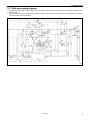
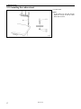
3-1. Table processing diagram
• The thickness of the table should be at least 40 mm, and it should be strong enough to bear the weight and vibration of the
sewing machine.
• Check that the control box is at least 10 mm away from the leg. If the control box and the leg are too close together, it may result
in incorrect sewing machine operation.
3181B
BAS-311H
4
3. INSTALLATION
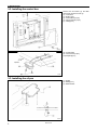
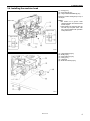
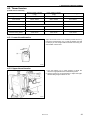
3-2. Installing the control box
Remove the six screws (1), and then
remove the control box cover (2).
(3) Control box
(4) Bolts [4 pcs.]
(5) Plain washers [4 pcs.]
(6) Spring washers [4 pcs.]
(7) Nuts [8 pcs.]
3033B
(8) Power switch
(9) Wood screws [2 pcs.]
(10) Staples [4 pcs.]
Operator
1841B
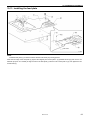
3-3. Installing the oil pan
(1) Oil pan
(2) Nails [6 pcs.]
(3) Waste oil tank
3034B
5
BAS-311H
3. INSTALLATION
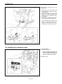
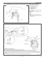
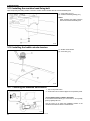
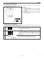
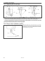
3-4. Installing the machine head
(1) Pins [2 pcs.]
(2) Set screws [2 pcs.]
(3) Hinge rubber assemblies [2 pcs.]
Place the machine head gently on top of
the oil pan.
Pulse motor
Approx. 20 mm
NOTE:
• Be careful not to get the cords
clamped between the machine head
and the oil pan.
• When holding the machine head, do
not hold it by the pulse motor. This
may cause problems with operation
of the pulse motor.
Approx. 20 mm
3035B
(4)
(5)
(6)
(7)
(8)
(9)
Hinge holders [2 pcs.]
Bolts [4 pcs.]
Plain washers [4 pcs.]
Nuts [4 pcs.]
Head rest
Bolts with washer [4 pcs.]
3036B
BAS-311H
6
3. INSTALLATION
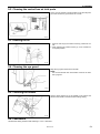
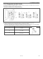
(10) Auxiliary plate
(11) Bolts with washer [8 pcs.]
Loosen the eight bolts with washer (11),
and adjust so that the auxiliary plate (10)
is 0 to 0.5 mm above the needle plate
(10). Gently tilt back the machine head.
Needle plate
NOTE:
• Install the auxiliary plate (10) so that
it is horizontal.
If the auxiliary plate (10) is lower than
the needle plate, the feed plate may
get caught on the needle plate.
• Two or more people should tilt back
the machine head, and it should be
tilted gently while being held with
both hands.
3037B
7
BAS-311H
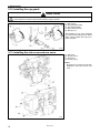
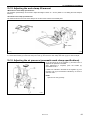
3. INSTALLATION
Be sure to
install so that
the side with
“UP” on it is
facing upward.
(12) Gas spring holders [2 pcs.]
(13) Spacer
(14) Bolt
(15) Nut
(16) Gas spring
(17) Shaft collars [2 pcs.]
(18) Gas spring shaft D
(19) Plain washers [2 pcs.]
(20) Retaining rings E [2 pcs.]
(21) Bolts [2 pcs.]
(22) Plain washers (medium) [2 pcs.]
(23) Plain washers (large) [2 pcs.]
(24) Spring washers [2 pcs.]
(25) Nuts [2 pcs.]
(26) Gas spring shaft U
(27) Retaining rings E [2 pcs.]
3038B
(28) Gas spring support cover
(29) Bolts with washer [6 pcs.]
3039B
BAS-311H
8
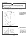
3. INSTALLATION
Gently return the machine head to its
original position.
1. Remove the two screws (30), and
then temporarily remove the machine
head switch (31).
2. Use the two screws (30) which were
removed to install the machine head
switch (31) in the position shown in
the illustration.
3. Check that the machine head switch
as turned on as shown in figure [A].
* If the machine head switch is not
turned on, adjust the installation
position while referring to “3-17.
Checking the machine head switch”.
3040B
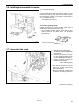
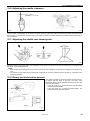
3-5. Installing the operation panel
(1) Operation panel
(2) Wood screws [4 pcs]
* Pass the panel cord through the
hole in the table, and then insert it
into the control box through the
hole in the side of the control box.
(3) Staples [3 pcs]
3041B
9
BAS-311H
3. INSTALLATION
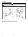
3-6. Installing the two-pedal foot switch
(1) Two-pedal foot switch
(2) Conversion harness
Connect the connector for the two-pedal foot switch (1) to the
conversion harness (2). Insert the conversion harness (2) into
the P15 (PEDAL) connector on the main P.C. board. (Refer to
"3-7. Connecting the cords".)
* Be sure to make the ground connection. (Refer to “3-8.
Connecting the ground wire”.)
<Foot switch operating method>
When the work clamp switch (left) is depressed, both work
clamps are lowered, and when the start switch (right) is
depressed, the sewing machine starts sewing.
* The work clamp lowering method can be changed using
memory switch No. 002. (Refer to "6-2. List of memory
switch settings.")
3042B
Work clamp switch (2-step)
Start switch
4923Q
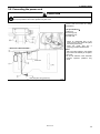
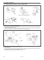
3-7. Connecting the cords
1. Gently tilt back the machine head.
2. Pass the cord bundle through the hole
in the work table.
3. Loosen the two screws (1), and then
open the cord presser plate (2) in the
direction of the white arrow and pass
the cord bundle through the opening.
4. Securely connect the connectors as
indicated in the table below.
(Refer to following page.)
NOTE:
• Check that the connector is facing the
correct way, and then insert it firmly
until it locks into place.
• Secure the cables with cable ties and
cord clamps, while being careful not to
pull on the connector.
3044B
(Continued on next page.)
BAS-311H
10
3. INSTALLATION
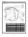
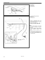
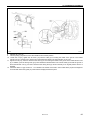
< Main P. C. board >
Lock the cord
clamp securely.
<Removal>
Press
the tab.
<Securing>
3046B
Connectors
X pulse motor encoder [5-pin] White
Y pulse motor encoder [5-pin] Blue
Work clamp pulse motor encoder [5-pin] Black
Machine head switch [3-pin]
Conversion harness (two-pedal foot switch) [7-pin]
White
Machine head memory [6-pin]
Thread trimmer solenoid [6-pin]
Digital tension [4-pin]
X pulse motor [4-pin] White
Y pulse motor [4-pin] Blue
Work clamp pulse motor [4-pin] Black
Operation panel [8-pin] Red
Home position sensor [12-pin] White
STOP switch [6-pin] White
Connection location on
main P. C. board
P17 (X-ENC)
P18 (Y-ENC)
P19 (P-ENC)
P14 (HEAD-SW)
P15 (PEDAL)
P16 (HEAD-M)
P2 (SOL1)
P3 (SOL2)
P21 (XPM)
P22 (YPM)
P23 (PPM)
P32 (PROGRAMMER)
P8 (SENSOR1)
P9 (HEAD)
Cord clamps
(2)
(2)
(2)
(2)
(2)
(2)
(1)
(1)
(1)
(1)
(1)
(2)
(2) (3)
(2) (3)
NOTE: Route the X, Y and work clamp pulse motor harnesses so that they do not touch the power supply P.C. board.
11
BAS-311H
3. INSTALLATION
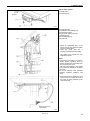
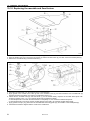
< Motor P. C. board >
Lock the cord clamps
(2) and (4) securely.
3047B
Connection location on
motor P. C. board
(UVW)
P11(SYNC)
P3 (PANEL)
Connectors
Upper shaft motor [4-pin]
Synchronizer [10-pin]
Operation panel [4-pin]
Cord clamps/
cable ties
(4)
(2) (3)
(2) (3)
5. Close the cord presser plate (2) in the direction of the white
arrow, and secure it by tightening the two screws (1).
NOTE:
Close the cord presser plate (2) securely so that no
foreign objects, insects or small animals can get inside the
control box.
6. Check that the cords do not get pulled, and then gently return
the machine head to its original position.
2291B
BAS-311H
12
3. INSTALLATION
3-8. Connecting the ground wire
CAUTION
Be sure to connect the ground. If the ground connection is not secure, you run a high risk of receiving a serious electric
shock, and problems with correct operation may also occur.
3045B
(1) Ground wire from the machine head
(2) Ground wire from operation panel
(3) Ground wires from two-pedal foot switch harnesses (2 wires)
• Tighten the control box cover with the six screws. Check that the cords are not clamped by the cover at this time.
NOTE: Make sure that the ground connections are secure in order to ensure safety.
13
BAS-311H
3. INSTALLATION
3-9. Connecting the power cord
CAUTION
Be sure to connect the ground. If the ground connection is not secure, you run a high risk of receiving a serious electric
shock, and problems with correct operation may also occur.
Connect cords that match the voltage
specifications.
< EU specifications>
(1) Filter box
(2) Screws [4 pcs]
(3) Staples [7 pcs]
(4) Power cord
1. Attach an appropriate plug to the
power cord (4). (The green and yellow
wire is the ground wire.)
2. Insert the power plug into a
properly-grounded electrical outlet.
< Seen from underneath table >
NOTE:
• Take care when tapping in the staples
(3) to make sure that they do not pierce
the cords.
• Do not use extension cords, otherwise
machine operation problems may
result.
Control box
Leg
Green and yellow wire (ground wire)
BAS-311H
2353B
14
3. INSTALLATION
<200 V system >
(1) Power switch
(2) Screws [2 pcs]
Operator
3146B
3147B
(3) 3-pin power supply connector
(4) Power cord
(5) Staples [5 pcs]
1. Attach an appropriate plug to the
power cord (4). (The green and yellow
wire is the ground wire.)
2. Insert the power plug into a
properly-grounded electrical outlet.
NOTE:
• Take care when tapping in the staples
(5) to make sure that they do not pierce
the cords.
• Do not use extension cords, otherwise
machine operation problems may
result.
3. Use the six screws to tighten the cover
of the control box. Check that none of
the cords are being clamped by the
cover at this time.
Green and yellow wire
(ground wire)
15
BAS-311H
3. INSTALLATION
<100 V / 400 V system >
(1) Power switch
(2) Screws [2 pcs]
Operator
3146B
2348B
(3) Transformer box
(4) Transformer box plates [2 pcs]
(5) Screw [with washer]
(6) 3-pin power supply connector
(7) Staples [6 pcs]
(8) Cord clamps [2 pcs]
(9) Power cord
1. Attach an appropriate plug to the
power cord (9). (The green and yellow
wire is the ground wire.)
2. Insert the power plug into a
properly-grounded AC power supply.
* The inside of the control box uses
single-phase power.
NOTE:
• If the ground connection is not secure,
electric shocks, operating errors or
damage to electronic components such
as P.C. boards may occur.
• Take care when tapping in the staples
(7) to make sure that they do not pierce
the cords.
• Do not use extension cords, otherwise
machine operation problems may
result.
3. Use the six screws to tighten the cover
of the control box. Check that none of
the cords are being clamped by the
cover at this time.
Green and yellow wire
(ground wire)
3156B
BAS-311H
16
3. INSTALLATION
3-10. Installing the cotton stand
(1) Cotton stand
NOTE:
Fit the washer (2), and then securely
tighten the nut (3) so that the cotton
stand does not move.
3043B
17
BAS-311H
3. INSTALLATION
3-11. Installing the pneumatic unit (pneumatic work clamp specifications)
Install underneath the work table.
(1)
(2)
(3)
(4)
Solenoid valve assembly
Washers [2 pcs.]
Wood screws [2 pcs.]
Rubber hose
After installing the pneumatic unit, adjust
the air pressure.
(Refer to "10-16. Adjusting the air
pressure".)
NOTE:
Make sure that the pneumatic unit
does not touch the control box or the
work table leg.
1904B
Connect each air tube to the position with the corresponding number.
Cylinder R
Cylinder L
Upper knob
Lower knob
Manual button
<Adjusting the speed controller>
You can use the valve knobs to adjust the lifting and lowering speeds.
The valve knobs should be adjusted so that the left and right sides of the work clamp operate at the same speed.
• When the upper knob is tightened, the lifting speed becomes slower. When it is loosened, the lifting speed becomes faster.
• When the lower knob is tightened, the lowering speed becomes slower. When it is loosened, the lowering speed becomes
faster.
You can operate the work clamp while the power is turned off by pressing the manual button.
BAS-311H
3097B
1905B
18
3. INSTALLATION
3-12. Installing the eye guard
CAUTION
Attach all safety devices before using the sewing machine.
If the machine is used without these devices attached, injury may result.
(1)
(2)
(3)
(4)
(5)
Bolt (loosen)
Eye guard (tilt forward)
Eye guard assembly
Plain washers [2 pcs.]
Bolts [2 pcs.]
After installing the eye guard assembly
(3), return the eye guard (2) to its original
angle, and then tighten the screw (1) to
secure it in place.
3048B
3-13. Installing the side cover and rear cover
3049B
(1)
(2)
(3)
(4)
Side cover
Screws [4 pcs.]
Rear cover
Screws [4 pcs.]
NOTE:
Be careful not to clamp the cords when
installing the side cover and the rear
cover.
3050B
19
BAS-311H
3. INSTALLATION
3-14. Lubrication
CAUTION
Do not connect the power cord until lubrication is complete.
If the foot switch is depressed by mistake, the sewing machine might start operating and injury could result.
Be sure to wear protective goggles and gloves when handling the lubricating oil and grease, so that they do not get into
your eyes or onto your skin. If the oil and grease get into your eyes or onto your skin, inflammation can result.
Furthermore, do not drink or eat the lubricating oil or grease. They may cause diarrhea or vomiting.
Keep the oil out of the reach of children.
The sewing machine should always be lubricated and the oil supply replenished before it is used for the first time, and also after
long periods of non-use.
Use only the lubricating oil <JX Nippon Oil & Energy Corporation Sewing Lube 10N; VG10> specified by Brother.
* If this type of lubricating oil is difficult to obtain, the recommended oil to use is <Exxon Mobil Essotex SM10; VG10>.
1. Fill the arm-side oil tank with oil.
2. Fill the bed-side oil tank with oil.
NOTE:
Be sure to fill the machine with oil
when the oil level is down to about
one-third full in the oil sight glass. If the
oil drops below the one-third level,
there is the danger that the machine
may seize during operation.
3051B
3. Pour oil in through the two holes of
the shuttle race base assembly so
that the felt (4) is lightly moistened.
NOTE:
・ The two pieces of felt (4) should
normally project by 0 to 0.5 mm
from the hook race. Be careful not
to push in the felt (4) when
lubricating.
・ If there is no more oil on the felt
(4) of the shuttle race base
assembly, problems with sewing
may result.
3071B
BAS-311H
20
3. INSTALLATION
3-15. Installing the machine head fixing bolt
When transporting the sewing machine, secure the machine head to the table with the machine head fixing bolt.
(1) Plain washer [2 pcs.]
(2) Machine head fixing bolts [2 pcs.]
NOTE:
When operating the sewing machine,
remove the machine head fixing bolt.
3052B
3-16. Installing the bobbin winder tension
(1) Bobbin winder tension
(2) Set screw [1 pc.]
3053B
3-17. Checking the machine head switch
1. Turn on the power switch.
2. Check that no error numbers appear on the operation panel.
<If error [E050], [E051] or [E055] is displayed>
If the machine head switch (1) is not turned on, error [E050],
[E051] or [E055] will occur.
Use the screw (2) to adjust the installation position of the
machine head switch as shown in the illustration.
3054B
21
BAS-311H
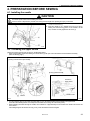
4. PREPARATION BEFORE SEWING
4. PREPARATION BEFORE SEWING
4-1. Installing the needle
CAUTION
Turn off the power switch before installing the needle.
If the foot switch is depressed by mistake, the sewing machine might start operating and injury could result.
1. Loosen the set screw (1).
2. Insert the needle (2) in a straight line as far as it will go,
making sure that the long groove on the needle is at the
front, and then securely tighten the set screw (1).
3057B
4-2. Threading the upper thread
Thread the upper thread correctly as shown in the illustration below.
* When using threading mode for threading, the tension discs (1) will open so that the thread can be threaded more easily.
(Refer to following page.)
3059B
[If using cotton thread or spun thread]
[If using synthetic thread]
Use the optional needle cooler unit.
Thread the
upper thread
Needle cooler
3060B
3058B
• Turn the machine pulley (2) and raise the thread take-up (3) to its highest position before threading the upper thread.
(This will make threading easier and it will prevent the thread from coming out at the sewing start.)
• When threading the thread through the needle, allow a distance of approximately 40 mm between the needle hole and the end
of the thread.
If the trailing length of the thread is too long, it may cause the thread to become tangled.
BAS-311H
22
4. PREPARATION BEFORE SEWING
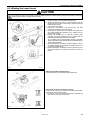
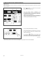
<Threading mode>
Threading mode is safe because the sewing machine will not start even when the foot switch is depressed.
1
Turn on the power switch.
3055B
2
Press the THREAD/CLAMP key.
All indicators switch off
• The work clamp will drop.
• The tension discs will open.
3
THREAD/CLAMP indicator illuminates
MENU indicator switches off
Threading the thread.
4
Ending threading mode
3061B 4427Q
Press the THREAD/CLAMP key.
• The work clamp will return to where it was before threading
mode was started.
THREAD/CLAMP indicator switches off
23
BAS-311H
2390B
4. PREPARATION BEFORE SEWING
4-3. Winding the lower thread
CAUTION
Do not touch any of the moving parts or press any objects against the machine while winding the lower thread, as this may
result in personal injury or damage to the machine.
3062B
3063B
1. Place the bobbin onto the bobbin winder shaft (1).
2. Thread the thread as shown in the illustration, wind the
thread around the bobbin several times, and then press the
bobbin presser arm(2).
3. Turn on the power switch.
4. Depress the foot switch to the second step. The feed
mechanism will move to the home position.
5. Check that the needle does not touch the work clamp, and
then while pressing the ENTER key (3), depress the foot
switch to the 2nd step.
6. Release the ENTER key (3) after the machine starts
operating, and keep depressing the foot switch until the
lower thread stops being wound onto the bobbin.
(If you release the foot switch before winding is complete,
and then depress it again while pressing the ENTER key (3),
winding will start again.)
7. Once winding of the set amount of lower thread (80 - 90% of
the bobbin capacity) is completed, the bobbin presser arm
(2) will return automatically.
8. Remove the bobbin, hook the thread onto the knife (4), and
then pull the bobbin in the direction of the arrow to cut the
thread.
2341B
3064B
Adjusting the bobbin winding amount
Loosen the screw (5) and move the bobbin presser (6).
Case A
3065B
If the thread winds onto the bobbin unevenly
Loosen the set screw (7) and move the bobbin wider tension
assembly (8) up and down to adjust.
* For case A, move the bobbin winder tension assembly (8)
down, and for case B, move it upward.
Case B
BAS-311H
24
4. PREPARATION BEFORE SEWING
4-4. Installing the bobbin case
CAUTION
Turn off the power switch before installing the bobbin case.
If the foot switch is depressed by mistake, the sewing machine might start operating and injury could result.
2534Q
30mm
3066B
1.
2.
3.
4.
5.
6.
2535Q
Pull the shuttle race cover (1) downward to open it.
While holding the bobbin so that the thread winds to the right, insert the bobbin into the bobbin case.
Pass the thread through the slot (2) and pull it out from the thread hole (3).
Check that the bobbin turns in the direction of the arrow when the thread is pulled.
Pass the thread through the lever thread hole (4), and then pull out approximately 30 mm of thread.
Hold the latch on the bobbin case and insert the bobbin case into the rotary hook.
25
BAS-311H
4. PREPARATION BEFORE SEWING
4-5. Thread tension
[Thread tension reference]
Specifications
Medium-weight materials
(-03[])
Heavy-weight materials
(-05[])
Seatbelt (-07[])
Upper thread
#50 or similar
#20 or similar
#4 or similar
Lower thread
#50 or similar
#20 or similar
#4 or similar
Upper thread tension (N)
0.8 − 1.2
1.4 − 1.8
1.2 − 2.0
0.2 − 0.3
Lower thread tension (N)
1.0 − 1.5
Pre-tension (N)
0.1 − 0.3
0.1 − 0.6
0.3 − 0.6
Needle
DP x 5 #16
DP x 17 #19
DP x 17 #25
Normal sewing speed
2,000 sti/min
2,000 sti/min
1,300 sti/min
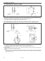
4-5-1. Lower thread tension
Adjust the thread tension to the weakest possible tension by
turning the thread tension nut (1) until the bobbin case will
not drop by its own weight while the thread end coming out
of the bobbin case is held.
Stronger
Weaker
2536Q
4-5-2. Upper thread tension
1. Turn the tension nut (1) (main tension) to adjust the
tension as appropriate for the material being sewn.
2. Use the tension nut (2) (sub tension) to adjust the upper
thread trailing length to about 40 mm.
Stronger
Weaker
Stronger
Weaker
3067B
BAS-311H
26
4. PREPARATION BEFORE SEWING
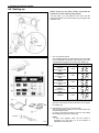
4-6. Starting up
2979B
Before turning on the power switch, check that the
needle bar is at the needle up stop position.
Turn the pulley (1) in the direction of the arrow until the
ridge at the bottom of the thread take-up (2) is aligned with
the index mark.
Aligned
3068B
1. Turn on the power switch.
The POWER indicator (3) will illuminate, and the model
name will appear in the tension value display (4) and the
specifications will appear in the section No. display (5).
Specifications
Medium-weight
materials
Motor-driven work
clamp
Medium-weight
materials
Pneumatic work
clamp
Heavy-weight
materials
Motor-driven work
clamp
Heavy-weight
materials
Pneumatic work
clamp
Seatbelts
Display
-03S
-03A
-05S
-05A
-07A
3151B
3152B
3153B
3154B
3155B
After this, the program number will flash in the program
No. display (6).
2. Depress the foot switch (7) to the 2nd step.
The sewing machine will move to the home position and
the work clamp will rise.
(If using a two-pedal foot switch, lower the work clamp
before depressing the start switch (8).)
2nd step
3160B
27
NOTE:
If error "UP" appears when the foot switch is
depressed, turn the pulley (1) in the direction of
operation to clear the error.
BAS-311H
5. USING THE OPERATION PANEL (BASIC OPERATIONS)
5. USING THE OPERATION PANEL (BASIC OPERATIONS)
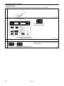
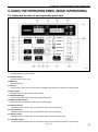
5-1. Name and function of each operation panel item
3070B
(1) Power indicator
Illuminates when the power is turned on.
(2) CAUTION indicator
Illuminates when an error occurs.
(3) RESET key
Used to reset errors.
(4) TEST key
Used to switch to test mode, or it can be used in combination with other keys to switch to other setting modes.
(5) TEST indicator
Illuminates when the TEST key (4) has been pressed.
(6) THREAD/CLAMP key
Used to start threading mode or work clamp height setting mode.
(7) THREAD/CLAMP indicator
Illuminates when the THREAD/CLAMP key (6) has been pressed.
(8) X-SCALE indicator
Illuminates when the SELECT key (14) is pressed to switch to the X-scale setting.
(9) Y-SCALE indicator
Illuminates when the SELECT key (14) is pressed to switch to the Y-scale setting.
(10) SPEED indicator
Illuminates when the SELECT key (14) is pressed to switch to the sewing speed setting.
(11) COUNTER indicator
Illuminates when the SELECT key (14) is pressed to switch to the lower thread or production counter setting.
BAS-311H
28
5. USING THE OPERATION PANEL (BASIC OPERATIONS)
(12) SPLIT No. indicator
Illuminates when the SELECT key (14) is pressed to show the split setting when split data (for specifying a pause while the
program is running) exists.
(13) WIPER indicator
Illuminates when the SELECT key (14) is pressed to switch to the thread wiper.
(14) SELECT key
Used to select the desired menu (horizontal and vertical scale, sewing speed, counter, (split No.), thread wiping).
(15) PROGRAM No. display
Shows information such as program numbers.
(16) Menu display
Displays information such as menu setting values, memory switch settings and error codes.
(17) Setting keys
Used to change the value which is displayed in the PROGRAM No. display (15).
(18) Setting keys
Used to change the value which is displayed in the menu display (16).
(19) TENSION key
Not used.
(20) TENSION indicator
Not used.
(21) SECTION No. display
Not used.
(22) TENSION display
Shows the program number when copying programs and using SD cards.
(23) Setting keys [+, -]
Not used.
(24) Setting keys [
]
Not used.
(25) ENTER key
Used to accept the values which are displayed in places such as the menu display (16).
(26) Function keys [F1, F2, F3, F4]
Used to directly select program numbers and cycle program numbers.
29
BAS-311H
5. USING THE OPERATION PANEL (BASIC OPERATIONS)
5-2. Program setting method
For details on the sewing data reading method, refer to “7. USING SD CARDS”.
1
Select the item to be changed.
Press the SELECT key.
2401B
・ The selected parameter changes in the order shown in
the illustration below each time the SELECT key is
pressed.
X-scale Y-scale Sewing speed Slow start pattern Counter Split No. Thread wiping
2
Change the setting for the parameter.
(Refer to “5-2-1. Parameter list” on the next page
for details on parameter changes.)
Press the
or
key to change the parameter setting.
3072B
3
Repeat steps 1 to 2 above to record the settings for each parameter.
* When memory switch No. 400 is set to ON, the horizontal scale, vertical scale, sewing speed and work clamp height can
be recorded separately for each program number.
* When memory switch No. 100 is set to ON, slow start patterns can be recorded separately for each program number.
* For details on memory switches, refer to “6-1. Setting memory switches”.
BAS-311H
30
5. USING THE OPERATION PANEL (BASIC OPERATIONS)
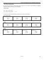
5-2-1. Parameter list
Parameter
Setting range and initial value
0% - 400%
(Limited by available sewing area.)
Display
Initial value
(Initial value is 100%.)
X-scale
* The setting can be displayed in “mm” units by
setting memory switch No. 402 to “ON”.
3073B
0% - 400%
(Limited by available sewing area.)
Initial value
(Initial value is 100%.)
* The setting can be displayed in “mm” units by
setting memory switch No. 402 to “ON”.
Y-scale
3074B
200 sti/min to 2800 sti/min
Setting units are 100 sti/min.
Initial value
(Initial value is 2000 sti/min.)
Sewing
speed
3075B
31
BAS-311H
5. USING THE OPERATION PANEL (BASIC OPERATIONS)
Parameter
Setting range and initial value
Lo1-Lo9
(Initial values: Lo4)
Display
Initial value
The starting-up speed at the sewing start can
be adjusted.
* The smaller the number, the slower the start.
* This is used to stop the thread from pulling
out at the sewing start, and at times when
skipped stitches might easily occur.
Slow start
pattern
3076B
(sti/min)
Sewing speed
for 1st stitch
Sewing speed
for 2nd stitch
Sewing speed
for 3rd stitch
Sewing speed
for 4th stitch
Lo1
Lo2
Lo3
Lo4
Lo5
Lo6
Lo7
Lo8
Lo9
200
200
300
400
400
400
400
600
800
200
300
400
400
500
600
800
1000
1200
300
400
500
600
800
1000
1200
1600
*1
500
600
700
900
1200
1400
*1
*1
*1
*1 Sewing will be carried out at the sewing speed which is set by the parameters.
Counter
Refer to “5-2-3. Using the production counter”.
Split No.
Refer to “5-2-4. Split number setting method”.
ON, OFF
(Initial setting is “ON”.)
Initial value
Thread
wiping
3158B
BAS-311H
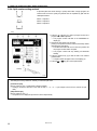
32
5. USING THE OPERATION PANEL (BASIC OPERATIONS)
5-2-2. Using the lower thread counter
If you use the lower thread counter to set the number of articles which can be sewn with the amount of lower thread available,
you can stop the lower thread running out in the middle of sewing a pattern.
<Initial value setting>
1
Change the mode to lower thread counter setting
mode.
Previous initial value
2
While pressing the TEST key, press the
key.
• The initial value which was set previously will appear in
the menu display.
TEST indicator and COUNTER indicator flash
Change the initial value.
3078B
3077B 2426B
Press the
or
key (1) to set the initial value.
• The initial value can be set from 1 ("0001") to 9999
("9999").
• If the initial value is set to "0000", the lower thread
counter will not operate.
• If you press the RESET key, the setting will become
“0000”.
• If the value is changed, the display will change to
flashing.
If you press the ENTER key during setting mode, the initial value for the program number
which was displayed before switching to setting mode will be memorized, and you can set the
lower thread counter separately for each program number.
3
Ending setting mode
Press the TEST key.
• The initial value will be memorized.
2404B
TEST indicator switches off
<Lower thread counter operation>
If the initial value is set to other than “0”, the lower thread counter will operate. (It operates even if the lower thread counter
display is not active.)
If you press the SELECT key so that the COUNTER indicator illuminates, the current counter value will be displayed in the
menu display (1).
3079B
33
1. Each time the sewing of a single article is completed, the
value shown in the menu display (1) is reduced by 1.
2. If the lower thread counter becomes "0000", the menu
display (1) and the COUNTER indicator (2) will flash and
a buzzer will sound. The sewing machine will not operate
during this time, even if the foot switch is depressed.
3. When you press the RESET key (3), the initial value for
the lower thread counter will appear in the menu display
(1) and sewing will be possible.
* You can press the
or
key (4) to set the lower
thread counter to the desired value. However, this value
will not be memorized as the initial value.
* If you press the RESET key (3) for 2 seconds or more,
you can return the lower thread counter to its initial value
even if the current value is not “0000”.
BAS-311H
5. USING THE OPERATION PANEL (BASIC OPERATIONS)
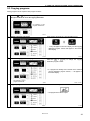
5-2-3. Using the production counter
<Setting the counter value>
1 Change the mode to production counter setting
mode.
While pressing the TEST key, press the
key.
・ The 7 digits of the current counter value will be
displayed in the PROGRAM No. display and the menu
display.
2
SPEED indicator illuminates
TEST indicator and COUNTER indicator flash
Change the counter value.
3080B 2430B
Press the
or
key (1) to set the counter value.
• The counter value can be set from [000][0000] to
[999][9999].
• If you press the RESET key during setting mode, the
value will become [000][0000].
• If the value is changed, the display will change to flashing.
For example,
1,234,500.
3081B
3
Apply the changed parameter setting.
Press the ENTER key.
Ending setting mode
・ The value will be applied and the display will change to
illuminated.
・ If you press the TEST key without pressing the ENTER
key, you can cancel the parameter changes.
Press the TEST key.
2414B
4
2404B
TEST indicator switches off
<Production counter operation>
The production counter is always operating. (It operates even if the production counter display is not active.) If you press the SELECT key so
that the COUNTER indicator illuminates when memory switch No. 300 is ‘ON’, the current production counter value will be displayed in the
menu display instead of the lower thread counter value. (The SPEED indicator will also illuminate at this time.)
1. The counter is incremented by 1 each time one sewing
operation is complete. If the production counter display is
active, the number being displayed in the menu display (1)
will be incremented by 1.
* If you would like the digits to be displayed in all columns, use
the temporary display function described below.
* If you press the RESET key (2) for 2 seconds or more, the
counter value can be reset to [0000].
Temporary display function
・ While pressing the ENTER key, press the F1 key. The
production counter will be displayed as 7 digits while the
keys are being pressed.
・ While pressing the ENTER key, press the F2 key. The lower
thread counter will be displayed while the keys are being
pressed.
3082B
BAS-311H
34
5. USING THE OPERATION PANEL (BASIC OPERATIONS)
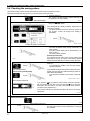
5-2-4. Split number setting method
If split data (data that causes sewing to pause) exists within a single program, the
numbers that are used to specify the patterns that are separated by split data are
called split numbers.
Pattern 1
Pattern 1: Split No. 1
Pattern 2: Split No. 2
Pattern 2
Pattern 3: Split No. 3
Pattern 3
4964Q
1. Press the
or
key (1) to select a program number for a
program that contains split data.
• The program number will flash in the PROGRAM No.
display (2).
2. Depress the foot switch to the 2nd step.
(If using a two-pedal foot switch, lower the work clamp before
depressing the start switch.)
• The feed mechanism will move to the home position and
the program number will be accepted.
• The program number will stop flashing and illuminate
steadily.
3. Press the SELECT key (3) so that the SPLIT No. indicator
(4) illuminates.
• The split number will appear in the menu display (5).
or
key (6) to set the split number.
4. Press the
2nd step
3083B
The setting for memory switch No. 403 lets you select the split mode.
[Continuous split]
Memory switch No. 403 = 0 (Split mode is always enabled)
• Sewing is carried out each time in the order of steps 1 → 2 → 3 → 1 (for example, if there are two sections of split
data).
[Independent split]
Memory switch No. 403 = 1
• The pattern for the displayed split number is sewn independently.
35
BAS-311H
5. USING THE OPERATION PANEL (BASIC OPERATIONS)
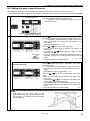
5-3. Copying programs
Sewing programs can be copied to other program numbers.
1
Press the
or
key to select the program number
that you would like to use as the copying destination.
For example, to copy
program number 200:
3084B
2
Switch to program copy mode.
While pressing the TEST key, press the SELECT key.
• “CoPy” will appear in the menu display, and the copying
destination program number will appear in the tension
value display.
3161B
3
2397B
Select the copying destination program number.
or
key to change the copying
Press the
destination program number.
* If a program has already been recorded in the selected
copying destination program number, “..” will appear in
the section display.
For example, to copy to
program number 201:
4
2382B 2383B
3085B
Copy the program.
Press the ENTER key.
• The program items will be copied.
3086B
BAS-311H
2414B
36
5. USING THE OPERATION PANEL (BASIC OPERATIONS)
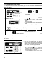
5-4. Checking the sewing pattern
Use test feed mode to operate the feed mechanism in order to check the needle movement.
Check that the needle hole does not come out from the frame of the work clamp.
1. Press the TEST key.
• The number of stitches remaining until the final stitch will
be displayed in the menu display.
1
2501B
TEST indicator lights
2. Press the
or
key (1) to set the program number
that you would like to check.
For example, program
number 200
If the PROGRAM No. display is flashing, depress the foot
switch to the 2nd step.
・ The feed mechanism will move to the home position and
the program number will change from flashing to
illuminated.
2nd step
2
Program No. flashes illuminates
Start continuous test feed mode.
3087B 4441Q
Depress the foot switch to the 2nd step and then release it.
・ The feed mechanism starts moving continuously one
stitch at a time.
(The stitch number display will be decremented by one
stitch at a time.)
・ The TEST indicator will flash.
[Fast-forward test mode]
If you depress the foot switch to the 1st step while the feed
mechanism is moving, the speed of the feeding operation
will become faster while the foot switch is being depressed.
If you would like to stop the feeding operation, press the
TEST key.
・ If you depress the treadle to the 2nd step, feeding
operation will restart.
4441Q
[Test interrupt mode]
2nd step
TEST indicator flashes
If you would like sewing to resume from the point where it was
paused, press the TEST key while test feeding is paused to
switch off the TEST indicator.
・ If you depress the treadle to the 2nd step, sewing will
start.
[Paused sewing standby mode]
2nd step
2404B 2416B 4441Q
TEST indicator switches off
・ If you press the
key (2) while this mode is active, the feed mechanism
key (3), the feed
will move forward by one stitch, and if you press the
mechanism will move back by one stitch. (The feed will move quicker if
you keep the key pressed down.)
・ If you press the RESET key, the feed mechanism will return to the sewing
start position.
2417B
3
Once the test feed reaches the final stitch, the feed
mechanism stops moving.
Press the TEST key.
2404B
TEST indicator switches off
4
1st step
Depress the foot switch to the 1st step.
The work clamp will rise and the preparation for sewing will
be completed.
4441Q
37
BAS-311H
5. USING THE OPERATION PANEL (BASIC OPERATIONS)
5-5. Setting the work clamp lift amount
The settings for the work clamp and intermediate work clamp lift amount can be changed using the operation panel.
* For pneumatic work clamp specifications, only threading mode and intermittent presser foot height setting mode will be available.
1
2
All indicators switch off
THREAD/CLAMP indicator illuminates
MENU indicator switches off
Motor-driven work clamp specifications only
Press the THREAD/CLAMP key.
The sewing machine will switch to threading mode.
• " 1" will appear in the PROGRAM No. display, and the work
clamp will be lowered.
3088B
Press the
key.
The sewing machine will switch to work clamp height setting mode.
• " 2" will appear in the PROGRAM No. display, and the work
clamp will be raised to the setting value which appears in the
menu display.
(Work clamp height setting: 15 − 25)
Press the
or
key to set the work clamp height.
• The work clamp will be raised or lowered to the height of the
setting value.
• If you press the
or
key to change the height, the height
display will flash.
• If you press the RESET key while the height display is flashing,
the setting value will return to the value before the change was
made.
3089B 2414B
• Press the ENTER key to accept the setting.
key.
When the setting value for memory Press the
The sewing machine will switch to intermediate work clamp
switch No. 003 is “2”
height setting mode.
• " 3" will appear in the PROGRAM No. display, and the work
clamp will move to the setting value that appears in the menu
display.
(Intermediate work clamp height setting: 1 − 15)
Press the
or
key to set the intermediate work clamp
height.
• The work clamp will be raised or lowered to the height of the
setting value.
• If you press the
or
key to change the intermediate work
clamp height, the height display will flash.
• If you press the RESET key while the height display is flashing,
the setting value will return to the value before the change was
made.
3090B
• Press the ENTER key to accept the setting.
NOTE:
When setting the work clamp height and the
intermediate presser foot work clamp height, check
that the slider (1) is touching the work clamp lifter
plate assembly (2).
3091B
BAS-311H
38
5. USING THE OPERATION PANEL (BASIC OPERATIONS)
3
Press the
key.
The sewing machine will switch to intermittent presser foot height
setting mode.
• " 4" will appear in the PROGRAM No. display, and the work clamp
will rise to the setting value that appears in the menu display.
(Intermittent presser foot height setting: 0.0 − 10.0)
Press the
or
key to set the intermittent presser foot height.
• The intermittent presser foot will rise or drop to the height of the
new value that has been set.
• If you press the RESET key while the height display is flashing,
the setting value will return to the value before the change was
made.
• Press the ENTER key to accept the setting.
NOTE:
After making the setting, be sure to turn the pulley once by hand
and check that the intermittent presser foot does not touch the
needle bar.
3092B
<Changing modes>
Motor-driven work clamp specifications
"
1" Threading mode
↑↓
" 2" Work clamp height setting mode
↑↓
" 3" Intermediate work clamp height setting mode (*)
↑↓
" 4" Intermittent presser foot height setting mode
* When the setting value for memory switch No. 003 is “2”
Pneumatic work clamp specifications
"
1" Threading mode
↑↓
" 4" Intermittent presser foot height setting mode
4
Ending setting mode
3093B
Press the THREAD/CLAMP key.
• The setting values will be memorized.
• The work clamp will return to where it was before setting mode
was started.
THREAD/CLAMP indicator switches off
Intermittent presser foot operation
Intermittent presser foot lift amount
Intermittent presser foot height
During standby
When lowered
While sewing
5033Q
39
BAS-311H
The settings can be made by the above
operations.
However, set the intermittent presser foot
height to a higher setting than the intermittent
stroke.
* If it is set smaller, the intermittent presser
foot will come into contact with the needle
plate.
Intermittent stroke
Refer to “10-14. Changing the intermittent
stroke” when making the adjustment.
6. USING THE OPERATION PANEL (ADVANCED OPERATIONS)
6. USING THE OPERATION PANEL (ADVANCED OPERATIONS)
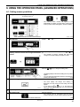
6-1. Setting memory switches
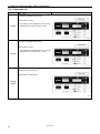
1
Change the mode to memory switch setting mode.
While pressing the TEST key, press the TENSION key.
All indicators switch off
・ The memory switch number will appear in the
PROGRAM No. display, and the setting value for that
memory switch number will appear in the menu display.
2
Menu indicator switches off, TEST indicator flashes
Select the memory switch that you would like to change
the setting for.
3094B 2421B
Press the
number.
or
key to select the memory switch
3095B
If you would like to display only the numbers of
memory switches that have been changed from default
settings
While pressing the SELECT key, press the
or
key
(1).
・ The numbers of memory switches that have been
changed from default settings will appear in order.
2423B
3
4
Change the memory switch parameters.
Press the
Apply the changed parameter setting.
・ The flashing display means that the setting has not yet been
applied.
・ You can make the initial setting appear in the display by
pressing the RESET key.
3096B
Press the ENTER key.
2414B
5
Repeat steps 2 to 4 above to set each memory switch.
6
Exit setting mode.
or
key to change the setting value.
・ The menu display will change from flashing to
illuminated, and this means that the setting has been
applied.
・ If you press the
or
key (1) or the TEST key
without pressing the ENTER key, you can cancel the
parameter changes.
Press the TEST key.
・ The changes will be memorized and the sewing
machine will switch to home position detection standby.
TEST indicator switches off
BAS-311H
2404B
40
6. USING THE OPERATION PANEL (ADVANCED OPERATIONS)
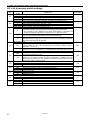
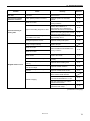
6-2. List of memory switch settings
No.
001
002
003
100
200
300
400
402
403
405
41
Setting
Setting items
range
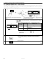
Work clamp lift timing after sewing is completed
0
Work clamp is not raised automatically.
1
Work clamp is raised at the final stitch position.
2
Work clamp is raised after moving to the home position.
Work clamp lowering sequence for separate work clamp (pneumatic specifications only)
0
Left and right work clamps are lowered at the same time.
1
Work clamp is lowered in the order left -> right.
2
Work clamp is lowered in the order right -> left.
Work clamp lowering operation (solenoid specifications only)
Analog lowering: Work clamp is lowered in direct proportion to the pedal
depression amount, and sewing starts when the pedal is fully depressed.
0
*This operation is only possible for foot switch specifications; for two-pedal foot
switch specifications, operation is the same as for a 2-step work clamp.
1-step work clamp: Work clamp is lowered when pedal is depressed to the 1st
1
step, and sewing starts when pedal is depressed to the 2nd step.
2-step work clamp: Work clamp is lowered to intermediate height when pedal is
2
depressed to the 1st step, and work clamp is fully lowered and sewing starts when
the pedal is depressed to the 2nd step.
Slow start method
The sewing speed for the first 5 stitches will be in accordance with the setting for
OFF
memory switch Nos. 151 to 155. (Ask the place of purchase for details on memory
switch Nos. 151 to 155.)
The sewing speed for the first 5 stitches can be selected from the nine slow start
ON
patterns “Lo1” to “Lo9”. (Refer to “5-2-1. Parameter list”.) The initial value is “Lo4”.
Single-stitch test feed
Test feed starts when the foot switch (start switch) is depressed, and it continues
OFF
automatically until the final stitch.
Test feed starts when the foot switch (start switch) is depressed, and it moves
forward by one stitch each time the switch is depressed. In addition, when the
ON
TEST indicator is illuminated, test feed will move forward one stitch at a time when
the machine pulley is turned by hand.
Production counter display
OFF
Lower thread counter display
ON
Production counter display
Sewing condition detail settings
OFF
Parameters which are common to all programs are used.
ON
Parameters can be set separately for each program.
Unit display for pattern zoom ratio
OFF
Displayed as %.
ON
Displayed as mm.
Split mode selection
0
Continuous split mode
1
Single split mode
Cycle program No. (C01 to C30) display
OFF
Disabled (not displayed)
ON
Enabled (displayed)
BAS-311H
Initial value
2
0
2
OFF
OFF
OFF
OFF
OFF
0
ON
6. USING THE OPERATION PANEL (ADVANCED OPERATIONS)
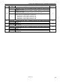
No.
406
407
408
409
410
Setting
Setting items
range
Program numbers switched by F keys
When the F1 to F4 keys are pressed, operation switches to sewing program
0
numbers 101 to 104.
When the F1 to F4 keys are pressed, operation switches to cycle program
1
numbers C01 to C04.
* Selection is possible when memory switch No. 400 is set to ON.
When the F1 to F4 keys are pressed, operation switches to the program number
which has been pre-assigned to the respective key.
Assignment to F1 key: Memory switch No. 407
2
Assignment to F2 key: Memory switch No. 408
Assignment to F3 key: Memory switch No. 409
Assignment to F4 key: Memory switch No. 410
Assignment to F1 key
100 to 999, If memory switch No. 406 = 3, operation switches to the program number which
C01 to C30 has been set.
Assignment to F2 key
100 to 999, If memory switch No. 406 = 3, operation switches to the program number which
C01 to C30 has been set.
Assignment to F3 key
100 to 999, If memory switch No. 406 = 3, operation switches to the program number which
C01 to C30 has been set.
Assignment to F4 key
100 to 999, If memory switch No. 406 = 3, operation switches to the program number which
C01 to C30 has been set.
BAS-311H
Initial value
0
101
102
103
104
42
6. USING THE OPERATION PANEL (ADVANCED OPERATIONS)
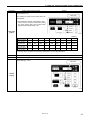
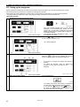
6-3. Using cycle programs
Sewing patterns that have been recorded in user programs can be recorded in up to 30 cycle programs (C01 to C30).
One cycle program can contain up to a maximum of 50 steps (St1 to St50).
When sewing the sewing patterns in a certain order, it can be useful to record them in a cycle program beforehand.
* If memory switch No. 400 is set to OFF, cycle program setting and selection cannot be carried out.
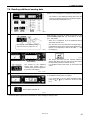
<Recording method>
1 Switch to cycle program recording mode.
While pressing the TEST key, press the
key (1).
2436B 2382B
3102B
2
TEST indicator flashes
Select a cycle program number.
・ The cycle program number (C01 to C30) will be
displayed in the PROGRAM No. display, the step
number (St1 to St50) will be displayed in the menu
display, and the program number will be displayed in
the TENSION display.
・ If no program has been recorded for a step, ‘---‘ will
be displayed for that step.
Press the
or
key to select the cycle program
number that you would like to use.
•
‘St 1’ will be displayed.
3103B
3
TEST indicator flashes
Select the program number to be recorded in step 1.
Press the
or
key (2) to display the program
number to be recorded in the TENSION display (3).
・ If the value is changed, the display will change to
flashing.
・ To cancel the recording, keep the RESET key
pressed for more than 2 seconds so that ‘---‘ is
displayed.
3104B
TEST indicator flashes
4
Apply the program setting.
2382B
2383B
Press the ENTER key.
2414B
・ The display will change from flashing to illuminated,
and this means that the setting has been applied.
・ If you press the / keys (4), the / keys (5) or
the TEST key without pressing the ENTER key, you
can cancel the parameter changes.
43
BAS-311H
6. USING THE OPERATION PANEL (ADVANCED OPERATIONS)
5
Repeat steps 3 and 4 above to record step 2 and
subsequent steps in the same way.
6
7
If you would like to continue setting another cycle program, repeat steps 2 to 5 above.
Press the
or
key (5) to display the step number
you would like to record in the menu display (6).
End cycle program recording mode.
Press the TEST key.
2404B
This completes the recording of cycle programs.
TEST indicator switches off
BAS-311H
44
6. USING THE OPERATION PANEL (ADVANCED OPERATIONS)
<Method of use>
When a cycle program has been recorded, the cycle program number is displayed after the program number when a program
number is selected.
1. Press the
or
key (1) to select the cycle program
number that you would like to use.
・
Program
for step 1
The cycle program number is displayed in the
PROGRAM No. display, the step number is displayed in
the TENSION display, and the parameter for that step is
displayed in the menu display (2).
・ When you press the SELECT key, the menu display (2)
and the menu indicator (3) are switched, so that you can
check the program parameters for that step.
parameter
Step No.
3105B
2.
Carry out sewing while referring to “8. Sewing”.
・
The recorded programs are carried out in the order of
the steps, and when the last step is completed, sewing
returns to the first step.
・
If you press the
or
key, you can return to the
previous step or skip to the next step respectively. (You
do not need to carry out home position detection again.)
3106B
* When memory switch No. 405 is set to OFF, the display of cycle programs can be turned off (skipped).
45
BAS-311H
2382B 2383B
6. USING THE OPERATION PANEL (ADVANCED OPERATIONS)
6-4. Direct selection
You can use the function keys to directly select program numbers and cycle program numbers. However, if a program
number has nothing recorded, it will not be displayed.
<Function keys>
2441B
The parameters which can be selected will vary depending on the memory switch settings.
406 = 0 (Initial setting)
Program No.102
Program No. 101
Program No.103
2443B
2442B
Program No.104
2444B
2445B
406=1
Program No.C02
Program No.C01
2442B
Program No.C03
2443B
Program No.C04
2444B
2445B
406=2
Item specified by memory
switch No. 407
2442B
Item specified by memory
switch No. 408
Item specified by memory
switch No. 409
Item specified by memory
switch No. 410
2444B
2445B
2443B
BAS-311H
46
6. USING THE OPERATION PANEL (ADVANCED OPERATIONS)
6-5. Resetting all settings to their defaults
If the sewing machine stops operating normally, the cause may be that an incorrect setting may have been made for the memory
data by means of memory switches, for instance. In such cases, it may be possible to restore normal operation by following the
steps given below to initialize the memory setting data.
1
Change to initialization mode.
3107B
(While pressing the RESET key, press the power ON
switch.)
‘1’ will be displayed in the PROGRAM No. display, and ‘ALL’ will
be displayed in the menu display.
[Reference]
If the
or
key (1) is pressed at this time, you can select the items to be initialized
as shown below.
* For details on initialization items other than “ALL”, contact the place of purchase.
PROGRAM
No. display
1
2
Main display
Initialization item
「ALL」
「MEM」
All data in memory is cleared or initialized.
Memory switch settings are initialized.
All sewing programs or individual programs
are cleared.
User program sewing conditions are
initialized.
Cycle programs are initialized.
3
「SEW」
4
「USE」
* To clear individual programs, press the
program number.
or
key to select the
3108B 2382B 2383B
2
Press the ENTER key for two seconds or more.
• The menu display will change to illuminated and initialization will then be
complete.
3
Press the TEST key.
2414B
2404B
47
BAS-311H
7. USING SD CARDS
7. USING SD CARDS
7-1. Notes on handling SD cards (commercially available)
• Use an SD card or a multimedia card with a capacity of 2GB or less.
• Do not disassemble or alter SD cards.
• Do not bend, drop, scratch or place heavy objects on top of the SD cards.
• Do not allow the SD cards to become wet, such as with water, oil, solvents, drinks or any other liquids.
• Do not use or store the SD cards in a locations exposed to strong static electricity or electrical interference.
• Do not use or store the SD cards in a locations exposed to vibrations or impacts, direct sunlight, extreme dust (or lint), high
temperatures, high humidity, severe temperature fluctuations, or strong magnetic forces (such as from speakers).
• Do not subject the SD cards to vibration or shocks or remove them from the sewing machine while data reading or writing
is in progress.
• Data on the SD cards may be lost or damaged due to some malfunction or accident. We recommend backing up important
data.
• The SD cards that you purchased is already formatted. We recommend that the SD cards not be reformatted.
• The recommended SD cards are those sold by SanDisk and Panasonic. Cards from other manufacturers may use different
formatting methods and may not work correctly as a result.
For additional information, refer to the instruction manual included with the SD cards that you have purchased.
* This product is compatible with SD cards that have been formatted using the FAT16/32 method. Cards that have
been formatted using other formatting methods cannot be used.
* All other company and product names mentioned in this instruction manual are trademarks or registered trademarks
of their respective companies. However, the explanations for markings such as TM are not clearly described within
the text.
7-2. Structure of an SD card folder
Data type
Folder name
File name
ISM19MN.BVP (Main control program)
ISM19MT.BVP (Motor control program)
ISM19PL.BVP (Panel control program)
Control program
\BROTHER\ISM\ISMSYS\
Sewing data
\BROTHER\ISM\ISMDB**\
* ‘**’ represents the value for memory switch No.
752. If you would like to keep additional sewing
data for different sewing machines on a single
SD card, change the folder name.
ISMS0***.sew
* ‘***’ represents the sewing data number.
Memory switch
Same as above
ISMMSW.SEW
Parameter
Same as above
ISMUPG.SEW
Cycle program
Same as above
ISMCYC.SEW
Error log
\BROTHER\ISM\ISMLDT\
Stores the files which relate to error logs.
BAS-311H
48
7. USING SD CARDS
7-3. Preparation for reading and writing data
Insert the SD card into the SD slot.
NOTE:
• Make sure the SD card is facing the correct way.
• The cover should be closed at all times except when
the SD card is inserted and removed, otherwise dust
may cause trouble.
1
2650B
2
3
Turn on the power switch.
Switching to SD data read/write mode
While pressing the TEST key, press the ENTER key.
2652B
・ “ sd” will appear in the PROGRAM No. display and
“read” will appear in the menu display while the SD
card is being read.
・ Once reading of the SD card is complete, the mode
number will appear in the PROGRAM No. display and
the setting for that mode number will appear in the
menu display.
・ The initial mode is additional sewing data reading
mode. (Refer to “Read/write mode list” below.)
TEST indicator flashes
3098B
Press the
4
or
key to select the mode.
For example mode No. w2
2653B
[Read/write mode list]
PROGRAM No.
display
Menu display
r1
[-Sew]
Additional sewing data is read from the SD card. *
w2
[Sew-]
Additional sewing data is written to the SD card.
r3
[-MEM]
Memory switch settings are read from the SD card.
w4
[MEM-]
Memory switch settings are written to the SD card.
r5
[-PrG]
Reads sewing program data and cycle program data from the SD card.
w6
[PrG-]
Writes sewing program data and cycle program data to the SD card.
r7
[-ALL]
Reads all sewing machine data (sewing program data, cycle program data, memory
switch settings and additional sewing data) from the SD card.
w8
[ALL-]
Writes all sewing machine data (sewing program data, cycle program data, memory
switch settings and additional sewing data) to the SD card.
w9
[LoG-]
Error log data is written to the SD card.
Setting items
* The additional sewing data that can be used with this sewing machine is data which has been created for the BAS-311H
or for the BAS-300G/311G.
49
BAS-311H
7. USING SD CARDS
7-4. Reading additional sewing data
Select the “ r 1” SD data read/write mode.
(Refer to “7-3. Preparation for reading and writing data”.)
1
・ The number of the additional sewing data in the SD
memory card folder will appear in the tension display.
(The initial value displayed is “ALL”.)
3098B
2
Press the
or
key to select the number for the
additional sewing data that you would like to be read
(ALL, 100 to 999).
・ When “ALL” is displayed, all of the additional sewing
data will be read at once.
For example, if the additional sewing
data to be read is for program No. 100
3099B
・ Only the data in the SD card folder corresponding to
the additional sewing data number will be displayed. (If
there is not a single item of data in the folder, “---“ will
be displayed.)
Press the ENTER key.
3
2414B
While reading
The number for the additional
sewing data number which is
currently being read will appear in
the tension value display.
2657B
・ The buzzer will sound and the selected additional
sewing data will be read from the SD card and copied
into the sewing machine's internal memory.
・ If no additional sewing data exists, an error buzzer will
sound.
3100B
When the display returns to the status in step 1, reading
of the additional sewing data is complete.
4
・ If you would like to use any other read/write modes,
press the
or
key to select the mode and then
run it.
3101B
5
Ending read/write mode
Press the TEST key.
TEST indicator switches off
2404B
* Contact the place of purchase for information on other reading and writing modes.
BAS-311H
50
8. SEWING
8. SEWING
WARNING
Do not allow any liquids to get onto this sewing machine, otherwise fire, electric shocks or operating problems may
occur.
If any liquid gets inside the sewing machine (machine head or control box), immediately turn off the power and
disconnect the power plug from the electrical outlet, and then contact the place of purchase or a qualified
technician.
CAUTION
Turn off the power switch at the following times.
If the foot switch is depressed by mistake, the sewing machine might start operating and injury could result.
• When threading the needle
• When replacing the bobbin and needle
• When not using the machine and when leaving the machine unattended
Do not touch any of the moving parts or press any objects against the machine while sewing, as this may result in
personal injury or damage to the machine.
8-1. Sewing
3109B
1st step
2nd step
4441Q
4979Q
1. Turn on the power switch.
or
key (1) to select the sewing program
2. Press the
number that you would like to use.
* Refer to "7-4. Reading additional sewing data" for
details on reading sewing data from a SD card.
3. Depress the foot switch to the 2nd step.
(If using a two-pedal foot switch, lower the work clamp
(3) before depressing the start switch (2).)
• The feed mechanism will move to the home position.
4. Place the material under the work clamp (3).
5. Depress the foot switch to the 1st step.
(If using a two-pedal foot switch, depress the work
clamp switch (4).)
• The work clamp will be lowered.
6. Depress the foot switch to the 2nd step.
(If using a two-pedal foot switch, depress the start switch
(2).)
• The sewing machine will start sewing.
7. After sewing is completed, the thread trimmer will
operate, and then the work clamp (3) will be raised.
Use a work clamp which will hold the material securely
so that it does not slip. If the material slips when using
the standard work clamp and feed plate, process them
so that the material does not slip.
3110B
51
BAS-311H
8. SEWING
8-2. Using the STOP switch
If you press the STOP switch (1) while sewing or test feeding is in progress, the CAUTION indicator (2) will illuminate and
the sewing machine will stop immediately.
3111B
<Clearing>
1. Press the RESET key (3).
• The thread will be trimmed, and then the CAUTION
indicator (2) will switch off and the buzzer will stop
sounding.
2. If you do not wish to continue sewing, press the RESET
key (3) once more.
• The program number will flash. Carry out preparation
for the next sewing.
3112B
<Continuing sewing from a stopping point>
If you have pressed the STOP switch (1) at times such as if the thread breaks while sewing or the lower thread runs out, you
can resume sewing from the point where the thread ran out.
1
Press the RESET key.
• The thread will be trimmed, and then the CAUTION indicator will switch
off and the buzzer will stop sounding.
2
Press the
key to return to the position where sewing stopped.
• When you press the
key, the feed mechanism will move backward
one stitch at a time, and when you press the
key, it will move forward
one stitch at a time. (The feed will move quicker if you keep the key
pressed down.)
3113B
3
2nd step
Depress the foot switch to the 2nd step.
(If using a two-pedal foot switch, depress the start switch.)
• The sewing machine will start operating and sewing will start.
4441Q
BAS-311H
52
9. CLEANING
9. CLEANING
CAUTION
Turn off the power switch before carrying out cleaning.
If the foot switch is depressed by mistake, the sewing machine might start operating and injury could result.
Be sure to wear protective goggles and gloves when handling the lubricating oil and grease, so that they do not get
into your eyes or onto your skin. If the oil and grease get into your eyes or onto your skin, inflammation can result.
Furthermore, do not drink or eat the lubricating oil or grease. They may cause diarrhea or vomiting.
Keep the oil out of the reach of children.
9-1. Cleaning the rotary hook
3114B
1. Pull the shuttle race cover downward to open it, and then
remove the bobbin case.
2. Open the setting claw (1) in the direction indicated by the
arrow, and then remove the shuttle race base (2) and the
shuttle hook (3).
3115B
3. Clean all the dust and thread ends from around the driver
(4), the top of the rotary hook thread guide and the
shuttle race.
3116B
53
BAS-311H
9. CLEANING
9-2. Cleaning the control box air inlet ports
Use a vacuum cleaner to clean the filter in the air inlet ports
(2) of the control box (1) at least once a month.
2309B
9-3. Draining the oil
1. Remove and empty the waste oil tank (1) whenever it is
full.
2. After emptying the waste oil tank (1), screw it back into
its original position.
3117B
9-4. Cleaning the eye guard
Wipe the eye guard clean with a soft cloth.
NOTE:
Do not use solvents such as kerosene or thinner to clean
the eye guard.
3118B
9-5. Checking the needle
Always check that the tip of the needle is not broken and
also that the needle is not bent before starting sewing.
3119B
9-6. Lubrication
Lubricate the sewing machine while referring to "3-14. Lubrication".
BAS-311H
54
10. STANDARD ADJUSTMENTS
10. STANDARD ADJUSTMENTS
CAUTION
Maintenance and inspection of the sewing machine
should only be carried out by a qualified technician.
Hold the machine head with both hands when tilting it
back or returning it to its original position.
In addition, do not apply excessive force when tilting
back the machine head. The sewing machine may
become unbalanced and fall down, and serious injury
or damage to the sewing machine may result.
Ask your Brother dealer or a qualified electrician to
carry out any maintenance and inspection of the
electrical system.
If the power switch needs to be left on when carrying
out some adjustment, be extremely careful to
observe all safety precautions.
Turn off the power switch and disconnect the power
cord before carrying out the following operations.
If the foot switch is depressed by mistake, the sewing
machine might start operating and injury could result.
• Inspection, adjustment and maintenance
• Replacing consumable parts such as the rotary
hook
If any safety devices have been removed, be
absolutely sure to re-install them to their original
positions and check that they operate correctly
before using the machine.
10-1. Checking the machine head switch
Check that the machine head switch is turned on as shown
in the illustration.
NOTE:
If the machine head switch is not turned on, errors
"E050", "E051" and "E055" will be generated.
3120B
55
BAS-311H
10. STANDARD ADJUSTMENTS
10-2. Thread take-up spring
Medium-weight materials
(-03[])
Specifications
Thread take-up spring
height (mm)
Thread take-up spring
tension (N)
Heavy-weight materials
(-05[])
7 − 10
0.2 − 0.5
Seatbelt (-07[])
2−4
0.6 − 1.2
1.0 − 1.4
<Thread take-up spring height>
Loosen the set screw (1) and turn the adjuster to adjust.
Lower
Higher
3121B
<Thread take-up spring tension>
Turn the tension stud (2) with a screwdriver to adjust the
tension.
Stronger
Weaker
3122B
NOTE:
If the thread tension spring is not adjusted correctly, the upper thread trailing length will be uneven after thread trimming.
10-3. Arm thread guide R
More thread
Less thread
The standard position of arm thread guide R (1) is when the
screw (2) is aligned with the index mark.
Loosen the screw (2) and move arm thread guide R (1) to
adjust.
* When sewing heavy material, move arm thread guide R
(1) to the left. (The thread take-up amount will become
greater.)
* When sewing light material, move arm thread guide R
(1) to the right. (The thread take-up amount will become
less.)
Index mark
3123B
BAS-311H
56
10. STANDARD ADJUSTMENTS
10-4. Adjusting the needle bar height
3124B
2552Q
Turn the pulley in the direction of the arrow to move the needle bar to the lowest position. Then remove the rubber plug (2),
loosen the screw (3) and then move the needle bar up or down to adjust so that the second reference line from the bottom
of the needle bar (reference line A) is aligned with the lower edge of the needle bar bush (1).
* If using a DP X 5 needle, use the highest reference line (reference line a).
10-5. Adjusting the needle bar lift amount and the driver needle guard
3125B
2544Q
Center of the needle
Tip
2927B
0135Q
1. Turn the pulley in the direction of the arrow to raise the needle bar from the lowest position until the lowest reference line
on the needle bar (reference line B) is aligned with the lower edge of the needle bar bush (1).
* If using a DP x 5 needle, align with reference line b which is the second reference line from the top.
2. Loosen the bolt (2).
3. Move the driver (3) back and forth to adjust so that it is touching the needle when the tip of the rotary hook is aligned with
the center of the needle, and then tighten the bolt (2).
NOTE:
If the driver (3) crosses the needle more than necessary, it will place a load on the needle, or it may cause poor thread
tension. Furthermore, if it does not cross the needle at all, the tip of the rotary hook will interfere with the needle and
skipped stitches may occur.
57
BAS-311H
10. STANDARD ADJUSTMENTS
10-6. Adjusting the needle clearance
0.01 − 0.08mm
(Seatbelt: 0.1 – 0.2 mm)
3126B
0138Q
Turn the pulley in the direction of the arrow to align the tip of the rotary hook with the center of the needle, and then loosen
the set screw (1) and turn the eccentric shaft (2) to adjust so that the clearance between the needle and the rotary hook is
0.01 to 0.08 mm.
10-7. Adjusting the shuttle race thread guide
3574Q
Install the shuttle race thread guide (1) by pushing it in the direction of the arrow so that the needle groove is aligned with
the center of the needle plate hole.
NOTE:
If the shuttle race thread guide is in the wrong position, thread breakages, soiled thread or tangling of the thread may
occur.
The position of the shuttle race thread guide is adjusted at the time of shipment from the factory. It should not be
changed if possible.
10-8. Rotary hook lubrication amount
More oil
The optimum position is when the head of the set screw (1)
is aligned with the edge of the bed. The rotary hook
lubrication amount can be adjusted within three turns to the
right from that position.
• If the set screw (1) is turned clockwise, the lubrication
amount becomes smaller.
• If the set screw (1) is turned counterclockwise, the
lubrication amount becomes greater.
Less oil
Aligned
3127B
BAS-311H
58
10. STANDARD ADJUSTMENTS
10-9. Adjusting the position of the movable knife
3059B
5232Q 3128B
<View from side of thread trimmer cam>
Reverse position
5233Q
5255Q
1. Open the top cover and tilt back the machine head.
2. Turn the pulley (1) by hand in the direction of the arrow to move the needle bar to its lowest position, and push the thread
trimming solenoid (2) as far as it will go.
3. With the collar (3) inserted into the groove of the thread trimmer cam (4), turn the pulley (1) by hand to set the driving lever
(5) to the reverse position (when the thread take-up (6) is close to its lowest position).
3129B
3130B
4. Loosen the two screws (7), and then remove the cover (8).
5. Loosen the bolt (9).
6. Move the movable knife connecting plate (11) back and forth to adjust so that the distance from the ridge on the right side
of the needle plate to the ridge on the movable knife (10) is 9.5 to 9.9 mm.
7. After tightening the bolt (9), check the above position once more.
59
BAS-311H
10. STANDARD ADJUSTMENTS
3059B
3145B
3131B
8. Replace the cover (8).
9. Turn the pulley (1) by hand to move the needle bar to its lowest position.
10. Loosen the nut (12), tighten the set screw (13) until the collar (3) is touching the inside of the groove in the thread
trimmer cam (4), and then turn it back in the counterclockwise direction by approximately 1/4 of a turn.
11. Tighten the nut (12), and then check that the collar (3) is not touching the inside of the groove in the thread trimmer cam
(4). In addition, push the driving lever (5) by hand toward the thread trimmer cam until the collar (3) touches the groove of
the thread trimmer cam (4), and then check that the driving lever (5) returns smoothly to its original position when it is
released.
12. Check that there is a gap of about 0 - 1 mm between the outside of the hole in the movable knife (10) and the ridge line
on the shuttle race thread guide (14) when there is still play between the parts.
BAS-311H
60
10. STANDARD ADJUSTMENTS
10-10. Replacing the movable and fixed knives
3132B
1. Loosen the two bolts (1) and then remove the feed plate (2).
2. Open the shuttle race cover, remove the two screws (3) and the two flat screws (4), and then remove the needle plate (5).
3. Remove the movable knife (6) and the fixed knife (7).
3133B
3134B
4. Install the new fixed knife (7) in the position shown in the illustration.
5. Apply grease to the outside of the collar (8) and to the shoulder screw (9), and then install the new movable knife (6)
together with the thrust washer (10) and the movable knife spacer (11).
6. Check that the movable knife (6) and fixed knife (7) cut the thread cleanly. Replace the movable knife spacer with
accessory spacers (t=0.2, 0.3, 0.4) so that the knives trim the thread accurately.
* If the knife pressure is too weak and the thread is not completely cut, use a thinner movable knife spacer.
* If the knife pressure is too strong and the movable knife (6) turns stiffly, use a thicker movable knife spacer.
7. Apply grease to the pin (12), place it into the movable knife connecting plate (13), and install it to the needle plate (5).
8. Check that the needle is aligned with the center of the needle hole.
61
BAS-311H
10. STANDARD ADJUSTMENTS
10-11. Installing the feed plate
Index mark
3135B
NOTE:
Install the feed plate (1) so that the surface with the index mark (U) is facing upward.
Place the rear edge of the feed plate (1) against the stepped part of base plate Y (2) (shaded section (A)) and use a 2 mm
diameter pin (such as a needle) to align the hole in the feed plate (1) with the hole in base plate Y (2); then tighten the two
socket bolts (3).
BAS-311H
62
10. STANDARD ADJUSTMENTS
10-12. Adjusting the thread wiper
Approx. 2mm
3136B
5008Q
Approx. 3mm
5009Q
1. Loosen the two screws (3) and shift the entire solenoid setting plate (4) up or down to adjust so that the thread wiper (2) is
15 mm in front of the needle center when the plunger (1) of the thread wiper solenoid is driven to the full stroke.
2. Loosen the screw (5) and adjust the position of the thread wiper (2) so that the distance from the thread wiper to the tip of
the needle is approximately 2 mm and the tip of the thread wiper (2) is approximately 3 mm from the center of the needle
when the thread wiper (2) passes below the needle during operation.
Note: Check that the thread wiper (2) does not touch the finger guard.
10-13. Presser foot installation position
Install the presser foot (1) with the screw (2) so that the
distance from the bottom of the presser foot to the top of the
needle plate is 22 mm when the sewing machine is stopped
and the presser foot (1) is raised.
5031Q
63
BAS-311H
10. STANDARD ADJUSTMENTS
10-14. Changing the intermittent stroke
The intermittent stroke can be adjusted to within 2 − 10 mm by adjusting the position of the stepping clamp connecting rod
and changing the installation position of stepping clamp link A.
<Changing the installation position of stepping clamp link A>
3137B
5011Q
1. Remove the face plate.
2. Remove the two screws (1) and the two shoulder screws (2), and then remove stepping clamp link A (3).
3. Change the installation position for stepping clamp link A (3) to either A, B or C above.
If the position of the stepping clamp connecting rod is adjusted as described in the following at any one of the installation
positions, the adjustment range for the intermittent stroke will as given in the following table.
Installation position
Intermittent stroke range
A
2 − 4.5mm
B
4.5 − 10mm
C
0 mm (Intermittent presser foot does not move
up and down)
BAS-311H
5012Q
64
10. STANDARD ADJUSTMENTS
<Stepping clamp connecting rod position adjustment>
5014Q
Index mark
3138B
5015Q
1. Loosen the screw (1), and then open the cover (2).
2. Loosen the nut (3), and then adjust the position of the stepping clamp connecting rod (4).
• When the stepping clamp connecting rod (4) is raised, the intermittent stroke will increase.
• When the stepping clamp connecting rod (4) is lowered, the intermittent stroke will decrease.
Next, adjust the needle bar and presser foot timing.
3. Turn the pulley in the direction of the arrow to raise the needle bar from the lowest position until the lowest reference line
on the needle bar (reference line B) is aligned with the lower edge of the needle bar bush (5).
(If using a DP x 5 needle, align with the second reference line from the top (reference line b).)
4. Open the top cover and loosen the two set screws (6).
5. Align the index marks on the stepping clamp cam (7) and the stepping clamp connecting rod (4), and then tighten the set
screws (6).
Check the following after changing the intermittent stroke.
3139B
3140B
Needle plate
1. With the intermittent presser foot (1) lowered, turn the pulley in the direction of the arrow to move the intermittent
presser foot (1) to its lowest position.
2. Check that the presser foot (1) does not touch the needle plate and that the presser bar clamp (2) does not touch
the presser bar bush (3).
<If they are touching>
Remove the motor cover (4).
Loosen the nut (5), and turn the bolt (6) until it is pressing against the intermittent drive lever (7), and then adjust until
the two points mentioned above are not touching.
65
BAS-311H
10. STANDARD ADJUSTMENTS
10-15. Adjusting the work clamp lift amount
<Motor-driven work clamp specifications>
The operation panel settings can be used to adjust the height to within 15 − 25 mm. (Refer to "5-5. Setting the work clamp lift
amount.")
<Pneumatic work clamp specifications>
The maximum lift amount for the work clamp is 30 mm above the surface of the needle plate.
Max. 30mm
5018Q
3143B
1. Turn on the air, and then depress the work clamp switch (1) to raise the work clamp (2).
2. Loosen the two bolts (4) of the work clamp arm lever (3), and move the work clamp arm lever (3) up or down to adjust.
10-16. Adjusting the air pressure (pneumatic work clamp specifications)
Lift up the handle (2) of the regulator (1) and then turn it to
adjust the air pressure to 0.5 MPa.
After adjustment is complete, push the handle (2)
downward to lock it.
If water has collected in the bottle of the regulator (1), turn
the drain cock (3) in the direction indicated by an arrow to
drain the water.
NOTE:
Open the air cock (4) slowly.
1912B
BAS-311H
66
10. STANDARD ADJUSTMENTS
10-17. If processing the work clamps and the feed plate to a shape that
matches the sewing pattern
Process the work clamps and feed plate which match the sewing pattern, while referring to the processing diagram below.
* Values in ( ) are the recommended sizes when sewing using the maximum area (150x100 mm).
<Work clamp processing diagram>
Motor-driven work clamp specifications
Pneumatic work clamp specifications
The left and right work clamps are symmetrical.
Center of sewing area
[mm]
<Feed plate processing diagram>
Recommended thickness 1.5 mm
Center of sewing area
Center of sewing area
[mm]
[mm]
3159B
67
BAS-311H
11. LIST OF ERROR CODES
11. LIST OF ERROR CODES
DANGER
Wait at least 5 minutes after turning off the power switch and disconnecting the power cord from the wall outlet
before opening the control box cover. Touching areas where high voltages are present can result in severe injury.
If a malfunction should occur with the sewing machine, a buzzer will sound and an error code will appear in the display
window. Follow the remedy procedure to eliminate the cause of the problem.
Warnings displayed as symbols
Code
CLdn
UP
Cause of error and remedy
The start switch was pressed without the work clamp being lowered.
First lower the work clamp.
The needle bar is not stopped in the needle up stop position.
Turn the pulley until the point where the error display disappears.
Switch-related errors
Code
Cause of error and remedy
The STOP switch was pressed.
E010
Press the RESET key to clear the error.
The STOP switch was pressed.
E011
Press the RESET key to clear the error.
Press the ▼ key to move the feed mechanism so that you can continue sewing.
The stop switch was still being pressed when the power was turned on, or there is a problem with the stop switch
E015
connection.
Turn off the power, and then check that connector P9 on the main P.C. board is properly connected.
Problem with the stop switch connection.
E016
Turn off the power, and then check that connector P9 on the main P.C. board is properly connected.
Start switch was being depressed when power was turned on.
E025
(For a one-pedal foot switch, the foot switch was being depressed to the 2nd step.)
Turn off the power and check the foot switch.
Work clamp switch was being depressed when power was turned on.
E035
(For a one-pedal foot switch, the foot switch was being depressed to the 1st step.)
Turn off the power and check the foot switch.
Machine head tilting was detected after the power was turned on.
E050
Turn off the power, and then return the machine head to its original position.
Check that connector P14 on the main P.C. board is properly connected.
Machine head tilting was detected while the sewing machine was operating.
E051
Turn off the power, and then check that connector P14 on the main P.C. board is properly connected.
Machine head tilting was detected when the power was turned on.
E055
Turn off the power, and then return the machine head to its original position.
Check that connector P14 on the main P.C. board is properly connected.
An operation panel key was still being pressed when the power was turned on, or key is faulty.
E065
Turn off the power and check the operation panel.
BAS-311H
68
11. LIST OF ERROR CODES
Motor-related errors
Code
Cause of error and remedy
E100
Turn off the power, add grease, and then carry out the specified reset operations.
Upper shaft did not stop at the needle up stop position when the sewing machine stopped.
E111
Turn off the power, and then check that connectors P11 and P1 on the motor P.C. board and connector P6 on the
main P.C. board are properly inserted.
Thread trimming was not completed.
E121
Turn off the power, and then check if the cutting edges of the fixed knife and movable knife are damaged or worn.
Sewing machine motor stopped due to a problem, or synchronizer is faulty.
Turn off the power, and then turn the pulley and check if the sewing machine has locked up. Check that
E130
connectors P11 and P1 on the motor P.C. board, connector P6 on the main P.C. board and connector P4 on the
upper shaft motor P.C. board are properly inserted.
Synchronizer is not connected correctly. Turn off the power, and then check that connector P11 on the motor P.C.
E131
board is properly connected.
Problem detected with sewing machine motor operation.
E132
Turn off the power, and then check that connectors P11 and P1 on the motor P.C. board, connector P6 on the
main P.C. board and connector P4 on the upper shaft motor P.C. board are properly inserted.
Sewing machine motor stopping position is incorrect. Turn off the power, and then check that connectors P11 and
E133
P1 on the motor P.C. board, connector P6 on the main P.C. board and connector P4 on the upper shaft motor
P.C. board are properly inserted.
Sewing machine motor is overheating, or temperature sensor is faulty.
Turn off the power, and then check the sewing machine motor.
E150
(When sewing data with a small number of stitches (15 stitches or less) is sewn repeatedly (short cycle
operation), the upper shaft motor may overheat and the “E150” error code may be generated.)
69
BAS-311H
11. LIST OF ERROR CODES
Feed mechanism-related errors
Code
Cause of error and remedy
X-feed motor home position cannot be detected. Problem with X-feed motor or poor X home position sensor
connection.
E200
Turn off the power, and then check that connectors P17, P21 and P8 on the main P.C. board are properly
connected. Check that LD1 on the main P.C. board is illuminated while the power is on. (If it is not illuminated,
fuse F2 is blown.)
X-feed motor stopped due to a problem. Turn off the power, and then check if there are any problems in the
X-feed direction.
E201
Turn off the power, and then check that connectors P17 and P21 on the main P.C. board are properly connected.
Check that LD1 on the main P.C. board is illuminated while the power is on. (If it is not illuminated, fuse F2 is
blown.)
X-feed motor stopped due to a problem during sewing. Turn off the power, and then check if there are any
problems in the X-feed direction. Turn off the power, and then check that connectors P17 and P21 on the main
E204
P.C. board are properly connected.
Check that LD1 on the main P.C. board is illuminated while the power is on. (If it is not illuminated, fuse F2 is
blown.)
X-feed motor stopped due to a problem while moving to the sewing start position. Turn off the power, and then
check if there are any problems in the X-feed direction. Turn off the power, and then check that connectors P17
E205
and P21 on the main P.C. board are properly connected.
Check that LD1 on the main P.C. board is illuminated while the power is on. (If it is not illuminated, fuse F2 is
blown.)
X-feed motor stopped due to a problem during test feeding. Turn off the power, and then check if there are any
problems in the X-feed direction. Turn off the power, and then check that connectors P17 and P21 on the main
E206
P.C. board are properly connected. Check that LD1 on the main P.C. board is illuminated while the power is on.
(If it is not illuminated, fuse F2 is blown.)
Y-feed motor home position cannot be detected. Problem with Y-feed motor or poor Y home position sensor
connection.
E210
Turn off the power, and then check that connectors P18, P22 and P8 on the main P.C. board are properly
connected. Check that LD1 on the main P.C. board is illuminated while the power is on. (If it is not illuminated,
fuse F2 is blown.)
Y-feed motor stopped due to a problem. Turn off the power, and then check if there are any problems in the
Y-feed direction.
E211
Turn off the power, and then check that connectors P18 and P22 on the main P.C. board are properly connected.
Check that LD1 on the main P.C. board is illuminated while the power is on. (If it is not illuminated, fuse F2 is
blown.)
Y-feed motor stopped due to a problem during sewing. Turn off the power, and then check if there are any
problems in the Y-feed direction. Turn off the power, and then check that connectors P18 and P22 on the main
E214
P.C. board are properly connected.
Check that LD1 on the main P.C. board is illuminated while the power is on. (If it is not illuminated, fuse F2 is
blown.)
Y-feed motor stopped due to a problem while moving to the sewing start position. Turn off the power, and then
check if there are any problems in the Y-feed direction. Turn off the power, and then check that connectors P18
E215
and P22 on the main P.C. board are properly connected.
Check that LD1 on the main P.C. board is illuminated while the power is on. (If it is not illuminated, fuse F2 is
blown.)
Y-feed motor stopped due to a problem during test feeding. Turn off the power, and then check if there are any
problems in the Y-feed direction. Turn off the power, and then check that connectors P18 and P22 on the main
E216
P.C. board are properly connected. Check that LD1 on the main P.C. board is illuminated while the power is on.
(If it is not illuminated, fuse F2 is blown.)
BAS-311H
70
11. LIST OF ERROR CODES
Work clamp-related errors
Code
Cause of error and remedy
Work clamp home position cannot be detected. Problem with work clamp motor or poor work clamp home
position sensor connection.
E300
Turn off the power, and then check that connectors P19, P23 and P8 on the main P.C. board are properly
connected. Check that LD1 on the main P.C. board is illuminated while the power is on. (If it is not illuminated,
fuse F2 is blown.)
Work clamp raised or lowered position cannot be detected.
Turn off the power, and then check if there are any problems in the work clamp vertical direction. Turn off the
E301
power, and then check that connectors P19 and P23 on the main P.C. board are properly connected. Check that
LD1 on the main P.C. board is illuminated while the power is on. (If it is not illuminated, fuse F2 is blown.)
71
BAS-311H
11. LIST OF ERROR CODES
Communication and memory-related errors
Code
Cause of error and remedy
Communication error detected between the main P.C. board and the panel P.C. board when the power was
turned on.
E400
Turn off the power, and then check that connector P1 on the panel P.C. board, connector P5 on the main P.C.
board and connectors P2 and P3 on the motor P.C. board are properly inserted.
Communication error detected between the main P.C. board and the motor P.C. board when the power was
turned on.
E401
Turn off the power, and then check that connector P1 on the panel P.C. board, connector P5 on the main P.C.
board and connectors P2 and P3 on the motor P.C. board are properly inserted.
Communication error detected between the main P.C. board and the panel P.C. board.
Turn off the power, and then turn it back on again. Turn off the power, and then check that connector P1 on the
E410
panel P.C. board, connector P5 on the main P.C. board and connectors P2 and P3 on the motor P.C. board are
properly inserted.
Communication error detected between the main P.C. board and the motor P.C. board.
Turn off the power, and then turn it back on again. Turn off the power, and then check that connector P1 on the
E411
panel P.C. board, connector P5 on the main P.C. board and connectors P2 and P3 on the motor P.C. board are
properly inserted.
Communication error detected between the panel and the programmer.
E412
Turn off the power, and then turn it back on again.
No SD card is inserted.
E420
Press the RESET key to clear the error.
Insert an SD card and then try again.
The program number is invalid or it has no corresponding data.
E421
Press the RESET key to clear the error.
Check that data for this program number is present on the SD card.
An error occurred while reading from the SD card.
Check the data.
E422
When reading 311G user programs, first read the sewing data.
Press the RESET key to clear the error.
Check the data on the SD card.
Insufficient free space on the SD card.
E424
Press the RESET key to clear the error. Use a different SD card.
An error occurred while writing to the SD card.
Check the SD card. The card may be write-protected.
E425
Press the RESET key to clear the error.
Use the specified type of SD card.
The program containing the specified cycle program has been cleared.
E427
Press the RESET key to clear the error. Redo the cycle program.
Data cannot be backed up to the main P.C. board (flash memory).
E430
Turn off the power, and then turn it back on again.
Data cannot be backed up to the main P.C. board (EEPROM).
E440
Turn off the power, and then turn it back on again.
Model selection cannot be read from the machine head memory.
E450
Turn off the power, and then check that connector P16 on the main P.C. board is properly connected.
Machine head memory is not connected.
E452
Turn off the power, and then check that connector P16 on the main P.C. board is properly connected.
Internal memory is full and copying is not possible.
E474
Press the RESET key to clear the error. Clear the sewing data.
BAS-311H
72
11. LIST OF ERROR CODES
Data editing-related errors
Code
Cause of error and remedy
The enlargement ratio setting caused the sewing data to extend outside the sewing area.
E500
Set the enlargement ratio again.
Press the RESET key to clear the error.
The enlargement ratio caused the data pitch to exceed the maximum pitch of 12.7 mm.
E502
Press the RESET key to clear the error. Set the enlargement ratio again.
Error in sewing data.
E510
Press the RESET key to clear the error. Re-read the pattern from the SD card. If the data still generates an error,
re-create the data.
No end code has been input into pattern data.
E511
Press the RESET key to clear the error.
Number of stitches exceeds allowed maximum.
E512
Press the RESET key to clear the error.
Memory switch file cannot be read correctly.
E581
The model for the data which was read does not match the model being written to.
Press the RESET key to clear the error. Read data for the same sewing machine model.
Memory switch versions do not match.
E582
Press the RESET key to clear the error. Read data for the same version.
User program versions do not match.
E583
Press the RESET key to clear the error. Read data for the same version.
Device-related errors
Code
Cause of error and remedy
Upper thread breakage occurred. Thread the upper thread. Re-sewing is then possible.
E600
Turn off the power, and then check that connector P14 on the main P.C. board is properly connected.
Problem with the lower thread detector.
E670
Turn off the power, and then check the lower thread detector.
Thread nipper motor home position cannot be detected. Problem with thread nipper motor or poor thread nipper
home position sensor connection. Turn off the power, and then check the position of the thread nipper lever.
E690
Clean underneath the needle plate to remove any thread scraps. Turn off the power, and then check that
connectors P4 and P20 on the main P.C. board are properly connected. Check that LD2 on the main P.C. board
is illuminated while the power is on. (If it is not illuminated, fuse F1 is blown.)
Abnormal thread nipper motor stop.
Turn off the power, and then check the position of the thread nipper lever. Clean underneath the needle plate to
E692
remove any thread scraps. Turn off the power, and then check that connectors P4 and P20 on the main P.C.
board are properly connected. Check that LD2 on the main P.C. board is illuminated while the power is on. (If it is
not illuminated, fuse F1 is blown.)
73
BAS-311H
11. LIST OF ERROR CODES
P.C. board-related errors
Code
Cause of error and remedy
Abnormal rise in power supply voltage.
E700
Turn off the power, and then check the input voltage.
Abnormal rise in sewing machine motor drive voltage.
E701
Turn off the power, and then check the voltage.
Abnormal drop in power supply voltage.
E705
Turn off the power, and then check the input voltage.
Abnormal current detected in sewing machine motor.
Turn off the power, and then check if there are any problems with the sewing machine. Turn off the power, and
E710
then check that connectors P11 and P1 on the motor P.C. board, connector P6 on the main P.C. board and
connector P4 on the upper shaft motor P.C. board are properly inserted.
Abnormal current detected in pulse motor.
E711
Turn off the power, and then check if there are any problems with the work clamp operation.
External error input (AIRSW) detected.
E730
Turn off the power, and then check the air pressure.
Version updating-related errors
Code
Cause of error and remedy
No control program is present.
E870
Install the control program.
Version update requests cannot be received.
E880
Turn off the power, and then turn it back on again.
Version updating did not complete normally.
E881
Turn off the power, and then repeat the version update procedure.
Communication error detected between the main P.C. board and the panel P.C. board.
E882
Turn off the power, and then check that connector P1 on the panel P.C. board, connector P5 on the main P.C.
board and connectors P2 and P3 on the motor P.C. board are properly inserted.
No control program is present on the SD card.
E883
Check that the control program has been saved into the correct folder.
There is a problem with the control program.
E884
Save the correct file onto the SD card.
E885~
Version updating could not be carried out. Turn off the power, and then turn it back on again.
E887
If an error code that is not listed above appears or if carrying out the specified remedy does not solve the problem,
contact the place of purchase.
BAS-311H
74
12. TROUBLESHOOTING
12. TROUBLESHOOTING
・ Please check the following points before calling for repairs or service.
・ If the following remedies do not fix the problem, turn off the power switch and consult a qualified technician or the place of
purchase.
CAUTION
Turn off the power switch and disconnect the power cord before carrying out these operations.
The machine may operate if the foot switch is depressed by mistake, which could result in injury.
Problem
Sewing machine does
not start when the
power is turned on and
the foot switch is
depressed.
Cause
Machine head switch does not work.
Remedy
Reference
Check if the machine head switch cord
is disconnected.
P. 11
Adjust the position of the machine head
switch.
P. 9
P. 55
If the machine head switch is
malfunctioning, replace it with a new
one.
Air cock is closed.
Open the air cock.
P. 66
Air pressure is too weak.
Adjust the regulator so that the air
pressure is about 0.5 MPa.
P. 66
Speed controller has been tightened
too far.
(Other than when using the thread
trimming cylinder)
Work clamp: Adjust the speed
controller by loosening it 4 turns from
the fully-tightened position.
P. 18
Thread wiper does not
work.
Thread wiper setting is OFF.
Set the thread wiper setting to ON.
P. 32
Adjust the position of the work clamp
arm lever.
P. 66
Work clamp does not
rise to the maximum
height.
Work clamp arm lever position is
incorrect.
*Pneumatic work clamp specifications
Work clamp arm assembly stopper
position is incorrect.
*Motor-driven work clamp
specifications
Work clamp does not
work.・Work clamp
* Pneumatic work clamp
specifications only
Work clamp pressure is
too weak.
* Pneumatic work clamp
specifications only
Work clamp pressure is
not uniform at front and
back of work clamp.
Thread wiper does not
operate correctly.
Adjust the position of the work clamp
arm assembly stopper.
Air pressure is too weak.
Adjust the regulator so that the air
pressure is about 0.5 MPa.
Work clamp is tilted.
Adjust the tilt of the work clamp.
The thread wiper is obstructing the
needle.
Thread wiper position is incorrect.
P. 66
Adjust the height of the thread wiper.
P. 63
Adjust the operating stroke of the
thread wiper.
P. 63
Adjust the operating stroke of the
thread wiper.
P. 63
(Continued on next page)
75
BAS-311H
12. TROUBLESHOOTING
Problem
Cause
Remedy
Reference
Lower thread winds to
one side.
Height of thread winder tension device
is incorrect.
Adjust the height of the thread winder
tension device.
P. 24
Lower thread winding
amount is incorrect.
Bobbin presser position is incorrect.
Adjust the position of the bobbin
presser.
P. 24
Amount of lower thread being fed out
from bobbin is too small.
Select a needle that is suitable for the
sewing conditions.
When threading the thread through the
needle, allow a distance of
approximately 40 mm between the
needle hole and the end of the thread.
Adjust the sub-tension so that the
upper thread trailing length after thread
trimming is approximately 40 mm.
Set the feeding amount to
approximately 30 mm.
Sewing start speed is too fast.
Adjust the sewing start speed.
Rotary hook tip is missing.
Replace the part.
Needle is too thick.
Upper thread trailing length is too short.
Thread unraveling at
sewing start.
Needle is too thin.
P. 22
P. 26
P. 25
P. 32
Select a needle that is suitable for the
sewing conditions.
P. 26
Needle is bent.
Replace the needle.
P. 22
Needle is not installed correctly.
Install the needle so that it faces
correctly.
P. 22
Needle and rotary hook tip are
touching.
Adjust the driver needle guard.
P. 57
Clearance between needle and rotary
hook tip is too large.
Adjust the needle clearance.
P. 58
Needle and rotary hook timing is
incorrect.
Adjust the needle bar lift amount.
P. 57
Needle is too thick.
Skipped stitches occur.
P. 26
Replace the needle hole plate with one
with a smaller needle diameter.
Use a thinner feed plate.
* Recommended thickness: 1.5 mm
Process the work clamps and the feed
plate into shapes that can hold the
material near the seam.
Adjust the intermittent height of the
intermittent work clamp.
Material is flapping.
P. 67
P. 67
P. 38
(Continued on next page)
BAS-311H
76
12. TROUBLESHOOTING
Problem
Upper thread is
breaking.
Lower thread is
breaking.
Needle breaks.
Upper thread is not cut.
Lower thread is not cut.
Cause
Remedy
Reference
Thread is too thick for the needle.
Select a thread which is suitable for the
needle.
P. 26
Needle is not installed correctly.
Install the needle so that it faces
correctly.
P. 22
Thread is not threaded correctly.
Thread the thread correctly.
P. 22
Damage or burring in parts such as the
rotary hook, needle hole plate, needle
or thread path.
Needle and rotary hook timing is
incorrect.
Repair the respective part by buffing it.
Alternatively, replace the part.
Adjust the needle bar lift amount.
P. 57
Upper thread tension is too strong.
Reduce the upper thread tension.
P. 26
Thread take-up spring tension is too
strong.
Reduce the tension of the thread
take-up spring.
P. 56
Thread breaks due to heat.
Use a needle cooler unit.
Reduce the sewing speed.
P. 22
P. 31
Damage to the needle hole plate or
bobbin case.
Repair the respective part by buffing it.
Alternatively, replace the part.
Lower thread tension is too strong.
Reduce the lower thread tension.
P. 26
Needle is bent.
Replace the needle.
P. 22
Needle is too thin.
Select a needle that is suitable for the
sewing conditions.
P. 26
Adjust the driver needle guard.
P. 57
Adjust the needle clearance.
P. 58
Needle and rotary hook timing is
incorrect.
Adjust the needle bar lift amount.
P. 57
Feed timing is too slow.
Advance the feed timing.
Movable knife is blunt.
Replace the movable knife with a new
one.
P. 61
Fixed knife is blunt.
Sharpen the fixed knife or replace it
with a new one.
P. 61
Adjust the needle bar lift amount.
P. 57
Adjust the standby position of the
movable knife.
P. 59
Movable knife is not picking up the
needle thread because the last stitch is
being skipped.
Refer to "Skipped stitches occur".
P. 76
Lower thread tension is too weak.
Increase the lower thread tension.
P. 26
Needle and rotary hook tip are
touching.
Movable knife is not picking up the
upper thread.
(Continued on next page)
77
BAS-311H
12. TROUBLESHOOTING
Problem
Cause
Upper thread is not
tight.
Remedy
Reference
Needle is too thin.
Select a needle that is suitable for the
sewing conditions.
P. 26
Hole diameter in needle hole plate is
too small.
Replace the needle hole plate with one
with a larger hole diameter.
Feed plate is too thin.
Use a thicker feed plate.
*Recommended thickness: 1.5 mm
Hole diameter of intermittent work
clamp is too small.
Sliding parts of outer rotary hook and
inner hook have little or no sewing
machine oil.
Damage or burring in parts such as the
rotary hook, needle hole plate, needle
or thread path.
Replace the intermittent work clamp
with one with a larger hole diameter.
Lower thread tension is too strong.
Reduce the lower thread tension.
Retard the feed timing.
Intermittent height of intermittent work
clamp is too low.
Adjust the intermittent height of the
intermittent work clamp.
P. 38
Adjust the driver needle guard.
P. 57
Adjust the needle clearance.
P. 58
Lower thread tension is too weak.
Increase the lower thread tension.
P. 26
Upper thread tension is too strong.
Reduce the upper thread tension.
*Adjust the upper thread tension after
adjusting the lower thread tension.
P. 26
Bobbin spinning
Use an anti-spin spring.
rotary
hook
tip
are
Upper thread trailing length is too long.
Movable knife is blunt.
Upper thread trailing
length is irregular.
P. 26
Feed timing is too fast.
0573M
Uneven thread
tightening at the sewing
start.
Poor seam finish on
underside of material at
the sewing start.
Repair the respective part by buffing it.
Alternatively, replace the part.
Thread take-up spring tension is too
weak.
Needle and
touching.
0574M
P. 20
Increase the upper thread tension.
*Adjust the upper thread tension after
adjusting the lower thread tension.
Increase the tension of the thread
take-up spring.
Upper thread tension is too weak.
Lower thread is not
tight.
Lubricate the felts for the sliding parts
of the outer rotary hook and inner hook.
Adjust the sub-tension so that the
upper thread trailing length after thread
trimming is approximately 40 mm.
Replace the movable knife with a new
one.
P. 26
P. 56
P. 26
P. 61
Fixed knife is blunt.
Sharpen the fixed knife or replace it
with a new one.
P. 61
Sub-tension is too weak.
Adjust the sub-tension.
P. 26
Thread take-up spring tension is too
weak.
Increase the tension of the thread
take-up spring.
P. 56
BAS-311H
78
13. 7-SEGMENT DISPLAY LIST
13. 7-SEGMENT DISPLAY LIST
4268M
79
BAS-311H
INSTRUCTION MANUAL
* Please note that the contents of this manual may differ slightly from the actual product purchased as a result of product improvements.
© 2013 Brother Industries, Ltd. All Rights Reserved.
This is the original instructions.
BAS-311H
SB4717-101 E
2013.09. B (2)