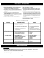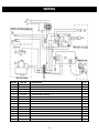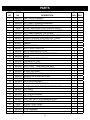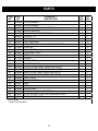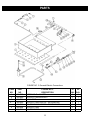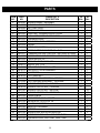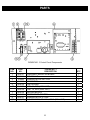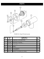
1
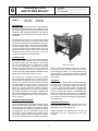
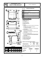
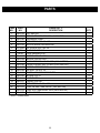
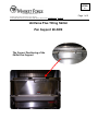
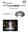
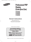
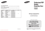
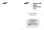
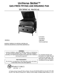
OWNER’S MANUAL UNIVERSE PLUS GAS SKILLET MODELS: 30P-STGL 30P-STGM 40P-STGL 40P-STGM WARNING: Improper installation, adjustment, alteration, service or maintenance can cause damage, injury or death. Read the installation, operating & maintenance instructions thoroughly before installing or servicing the equipment. FOR YOUR SAFETY: Do not store or use gasoline or other flammable vapors or liquids in the vicinity of this or any other appliance. CAUTION: Instruction to be followed in the event the user smells gas shall be posted in a prominent location. This information shall be obtained by consulting the local gas supplier. An Employee Owned Company Form No.: S-6003 Rev. B 11/06 PRINTED IN USA 35 Garvey Street • Everett • MA • 02149-4403 Tel: (617) 387-4100 • Toll Free: (866) 698-3188 Fax: (617) 387-4456 • Outside MA Fax: (800) 227-2659 E-Mail: [email protected] • Website: www.mfii.com TABLE OF CONTENTS SPEC SHEET INFORMATION ................................... 1 INSTALLATION ........................................................... 3 OPERATION ............................................................... 4 TEST KITCHEN BULLETIN ........................................ 5 TROUBLE-SHOOTING ............................................... 8 MAINTENANCE .......................................................... 8 WIRING ....................................................................... 9 PARTS ........................................................................ 10-18 INTRODUCTION NOTICE: THE FOLLOWING FAUCETS ARE THE ONLY ONES APPROVED BY THE MASSACHUSETTS BOARD OF REGISTRATION OF PLUMBERS AND GAS FITTERS FOR INSTALLATION ON THIS EQUIPMENT. SINGLE PANTRY FAUCET MANUFACTURED BY T & S BRASS AND BRONZE WORKS, INC. MODEL # B-0305 OR CONCEALED MIXING FAUCET WITH 4-ARM HANDLES MANUFACTURED BY T & S BRASS AND BRONZE WORKS, INC. MODEL # B-0512. IMPORTANT: • Installing, Operating and Service Personnel: • Installation of the equipment should be performed by qualified, certified, licensed and/or authorized personnel who are familiar with and experienced in staTe/local installation codes. • Operation of the equipment should be performed by qualified or authorized personnel who have read this manual and are familiar with the functions of the equipment. • Service of the equipment should be performed by AN AUTHORIZED MARKET FORGE SERVICE AGENT. SHIPPING DAMAGE CLAIM PROCEDURE: The equipment is inspected & crafted carefully by skilled personnel before leaving THE factory. The transportation company assumes full responsibility for safe delivery upon acceptance of this equipment. If shipment arrives damaged: 1. Visible loss or damage: Note on freight bill or express delivery and have signed by the person making delivery. 2. File claim or damages immediately Regardless of the extent of damages. 3. Concealed loss or damage: If damage is noticed after unpacking, notify the transportation company immediately and file ‘concealed Damage’ claim with them.This should be done within fifteen days from the date delivery is made to you. Retain container for inspection. Identify immediately i G MODELS: UNIVERSE PLUS GAS TILTING SKILLET ● 30P-STGL ● 30P-STGM JOB NAME: ___________________________ ITEM NO.: ____________________________ NO. REQUIRED: _______________________ ● 40P-STGL ● 40P-STGM DESCRIPTION: The Market Forge Gas Universe Plus Tilting Skillets are available in 30-gallon (87-liter) and 40-gallon (114-liter) pan bodies with 93,000 BTU and 126,000 BTU inputs respectively. Both models are available in open-leg and closed-base frame assemblies with manual or power tilt capabilities. The heavy duty construction of our Universe Plus Skillets incorporates sides formed of 10 gauge stainless steel and a 5/8” thick stainless steel clad plate that will provide a rigid flat cooking surface with improved heat distribution. The balanced design of the pan allows the operator to easily and quickly tilt to the desired position. Our new power tilt operates smoothly, with manual override that works easily when needed and without the use of tools or drills as required by other manufacturers. Construction: The Universe Plus Skillet has a fully polished stainless steel cooking surface that prevents food from adhering and helps to safely clean the equipment. Gas burners turn off automatically when the cooking pan is tilted from the horizontal position. The skillet is provided with a heavy-duty spring assisted cover and a condensate vent. The cooking pan and cover are supported by two consoles with a fully welded stainless steel tubular frame system that provides stable support to the unit. 30P-STGL Shown burners. An interlock switch is provided to turn the burners off when the pan is tilted more than 10° from the normal horizontal position. The spring assisted cover with integral vent, condensate drip guide and full width handle affords effortless operation and will maintain an open position. The consoles are completely covered with stainless steel that provides protection to the controls and is also easily cleanable and provides clear access for easy floor cleaning. The closed-base model incorporates an easily removable stainless steel front panel. The sloped front of the pan allows for complete draining of the pan when tilted to 70°. The tilting mechanism includes a precision ground and polished worm for smooth and long lasting tilt operation and positive control with a collapsible hand crank. A power tilting option is available and is also supplied with the collapsible handle for manual override operation if required. Controls: The skillet comes standard with a solid-state temperature control with a positive OFF position and 100°-450° Fahrenheit scale, a pilot light to indicate when the burners are ON, spark pilot ignition system as standard and a 1 hour mechanical timer is included. The optional power tilting mechanism also utilizes an UP/DOWN rocker switch. The manual tilting mechanism uses a collapsible hand crank conveniently located below the control panel. The controls are resistant to dripping and light splashing water (NEMA T-2). TECHNICAL SPECIFICATIONS: Cooking Pan: The unitized cooking pan with integral clad plate cooking surface is welded with full penetration to resist cracking due to expansion and contraction. The polished cooking surface resists product adherence and improves cleanup and appearance. The pan incorporates an easy-pour lip and 5-gallon increment markings. The clad plate cooking surface has integrally welded labyrinth fins for positive control and heat transfer from the reliable atmospheric OPERATION SHALL BE BY: The Universe Tilting Plus Skillets models 30P-STGL and 30P-STGM’ will be rated at 93,000 BTU at 3.5” W.C. natural gas and 10” W.C. propane gas. Models 40P-STGL and 40P-STGM will be rated at 126,000 BTU at 3.5” W.C. natural gas and 10” W.C. propane gas. 1 G UNIVERSE PLUS GAS TILTING SKILLET DETAILS & DIMENSION SERVICE CONNECTIONS Gas Fired G Gas Connection - Supplied through 3/4" NPT pipe. A gas shut-off valve must be installed in supply piping convenient and adjacent to appliance. E Electrical Connection - 120V units supplied with 8' foot cord with 3 prong plug. CW Cold Water - 3/8" O.D. NPT to faucet (Optional). HW Hot Water - 3/8" O.D. NPT to faucet (Optional). OPTIONAL AT EXTRA COST: ● 2” Draw-Off Valve with Strainer. ● Modular Joining Kit. ● Pan Support. ● Pan Holder Inserts. ● Pouring Lip Strainer. ● Single Pantry Faucet. ● Posi-Set. ● 2” Tangent Draw-Off Valve with Drain Hose Assembly, Includes: ○ 2” Tangent Draw-Off Valve with Strainer. ○ 90o Stainless Steel Elbow. ○ 8 Foot Long of 2” ID Hose (cut to required length). ○ Hose Clamp. ● Drain Cup Assembly, Includes: ○ Stainless Steel Cup Assembly. ○ 8 Foot Long of 2” ID Hose (cut to required length). ○ Hose Clamp. ● Drain Pan Assembly, Includes: ○ 6” x 12” x 20” Stainless Steel Solid Pan with Elbow. ○ 8 Foot Long of 2” ID Hose (cut to required length). ○ Hose Clamp. ● Double Pantry Faucet. ● Single Pantry Spray Hose. ● Double Pantry Spray Hose. ● Caster Kit w/Strain Relief. ● Correctional Package. MANIFOLD GAS PRESSURE AND INPUTS: W.C. 30 Gallon 40 Gallon BTU BTU Natural Spark Pilot 3.5" 93,000 126,000 Propane Spark Pilot 10" 93,000 126,000 NOTE: HIGH ALTITUDE - If equipment is to be installed above 2,000 feet specify installation height, so that p roper gas orifices can be provided. DIMENSIONS MODEL CAPACITY 30P-STGL 30 Gallon 114 liter 30P-STGM 40P-STGL 40P-STGM 40 Gallon 152 liter inches mm A 36 914 inches mm 46 1168 B 34.63 879 C 30.5 775 D 25.75 654 44.63 40.5 1133 1029 25.75 654 CLEARANCE: Left Side Right Side Back 2 30 GALLON 93,000 BTU 0" 0" 6" 40 GALLON 126,000 BTU 0" 0" 6" INSTALLATION carrier immediately if damage is found. 3. Remove screws holding unit to skid. 4. Transfer unit to desired position and make level and steady by adjusting feet to compensate for floor irregularities. Bolt the flange feet to the floor. 5. Raise skillet cover to full open position. Raise skillet by turning crank clockwise. Check to make sure burners and carryover tube are in position and securely seated. 6. Lower skillet by turning hand crank counterclockwise until fully seated on frame. Skillet is equipped with interlock switch, which does not permit burners to ignite until skillet is lowered to less than 10o off normal horizontal cooking position. 7. Gas service conditions: a. This unit is factory-adjusted for gas consumption of 93,000 BTU/Hour (on 30 Gallon units) or 126,000 BTU/ Hour (on 40 Gallon units) at the pressure indicated. Please read rating plate on top of control box. If this plate is marked for a different gas than that supplied, notify your dealer immediately. DO NOT CONNECT GAS LINES. Only qualified installer or service person should make the installation. b. Use new 3/4 I.P.S. iron or steel pipe complying with ANSI Standard for wrought-steel and wrought-iron. CAUTION: BE SURE TO READ! ► Keep this appliance area free and clear of combustibles. ► Do not obstruct the flow of combustion and ventilation air. ► Allow adequate ventilation to unit. Install under exhaust hood. ► Keep this manual for future reference. ► This installation must conform with local codes, or in the absence of local codes, with the National Fuel Gas Code, ANSI 2223. 1/NFPA 54, or the Natural Gas and Propane Installation Code, CSA . B 149.1, as applicable. ► The appliance and its individual shut off valve must be disconnected from the gas supply piping system during any pressure testing of that system at pressures in excess of 1/2 PSI (0.035 kg/cm2). ► The appliance must be isolated from the gas supply piping system by closing its individual manual shut off valve during any pressure testing of the gas supply piping system at test pressures equal to or less than 1/2 PSI (0.035 kg/cm2). Pipe B36- latest edition, properly threaded, reamed and free from chips, oil and dirt. ► This unit is serviceable from the front. Do not install in such a manner that a service person cannot remove front panels if provided. If pipe dope is used, apply a moderate amount, leaving two end threads bare. Gas connection is on the rear of the right console. Pipe in a gas shut-off valve accessible to the operator. c. Natural gas units are equipped with a pressure regulator factory-adjusted to give 3.5” (89mm) water column manifold pressure. The supply pressure must be at leaset 7” (178mm) water column pressure. d. Propane gas units are equipped with a pressure regulator factory-adjusted to give 10” (254mm) water column manifold pressure. The supply pressure must be at least 11” (279mm) water column pressure. e. Maximum supply pressure must not exceed 1/2 PSI (.035 kg/cm2) for both natural and propane gas. f. Perform a gas leak test of all newly-made joints, as well as those leading to the main gas control valve pilot burner, using a soap solution. DO NOT USE FLAME! ► Electrical grounding must be provided in accordance with local codes, or in the absence of local codes, with the National Electrical Code, ANSI/NFPA 70, or the Canadian Electrical Code, CSA C22.2, as applicable. ► In Canada, this installation must conform to C.S.A. Standard C22.1 Canadian Electrical Code, Part 1. ► The wiring diagram adhesive label is located on the inside of the control box cover. ► The product must be installed in a room with adequate air supply for complete gas combustion. 8. Electrical service connection - Connect skillet controls to 110/120 volt AC, 60 Hz, 1 pH (phase) branch circuit rated 15 Amps capacity. Wiring will conform to the requirements of national and local electrical codes. ONLY A LICENSED ELECTRICIAN SHOULD MAKE ELECTRICAL CONNECTIONS! ► Do not place on or directly against the unit any objects that would block air openings into the combustion chamber. ► Suitable for use on combustible floors. ► Clearances from both combustible and non-combustible contruction are 0” from side walls, 10” (254mm) from rear wall. ► This unit has a flexible cord wired into electrical system. CASTER INSTALLATION: Adequate means must be provided to limit the movement of the applicance without depending on the connector and quick disconnect device or its associated piping to limit the appliances movement. GENERAL INSTALLATION: 1. Remove carton from skid, being careful not to dent or scratch finished surface of the unit. 2. Inspect unit carefully for shipping damage. File clam with The location (s) where the restraining means may be attached to the appliance shall be approximately 3” below the gas inlet on the rear of the right hand console. 3 INSTALLATION operator know that the burners are cycling to maintain temperature. 6. If gas supply is interrupted durning operation, turn the THERMOSTAT dial to OFF position and turn the gas supply OFF. Wait five minutes, then repeat steps 1 through 4 to restart. 7. Turn the THERMOSTAT dial to OFF when braising pan is not in use. BEFORE FIRST USE: Using a non-corrosive, grease-dissolving commercial cleaner, clean the protective metal oils from all surface parts and the interior of the tilting braising pan (follow the cleaning instructions in the maintenance section of this manual) and wipe dry with a soft clean cloth. START-UP PROCEDURE: 1. Open manual gas shut-off valve. 2. Ensure that the braising pan is in the DOWN position. 3. Turn the THERMOSTAT dial to desired setting. The RED TEMPERATURE LIGHT will come on. This will turn on the electronic ignition on, which will light the burners. 4. If the burners do not come on after 30 seconds, turn the THERMOSTAT dial to OFF and then ON again to restart. 5. When braising pan has reached set temperature, the RED TEMPERATURE LIGHT will go OFF and the burners will shut OFF. The RED TEMPERATURE LIGHT will blink ON and OFF thereafter when the burners are OFF letting the SHUTDOWN INSTRUCTIONS: Turn the THERMOSTAT dial counterclockwise to the OFF position. PROLONED SHUTDOWN: 1. Turn the THERMOSTAT dial counterclockwise to the OFF position. 2. Turn the GAS VALVE located at the right rear to the OFF position. OPERATION 9. For cleaning instructions, See Trouble-Shooting and Maintenance Section. BEFORE FIRST USE: 1. Check to see that the correct gas connection has been made to the unit (110/120 volt connection). 2. Be sure skillet has been or is cleaned before using. 3. Be certain skillet is lowered to the normal horizontal cooking position so burners will light. 4. Set the thermostat to the desired temperature. See Test Kitchen Bulletin Section for thermostat settings. 5. Preheat to desired setting before grilling, pan frying, or any other type of cooking except boiling. 6. Cover should be up for most types of cooking, except simmering or boiling. The cover has a lip at the rear that will direct condensate into the skillet rather than onto the cabinet base. 7. When food is cooked, it should be immediately removed from skillet to prevent overcooking. 8. To lower skillet, merely turn tilt skillet hand crank counter clockwise. To raise skillet, turn hand crank clockwise. CAUTION: BE SURE TO READ: ► Disconnect the power supply to skillet before cleaning or servicing. ► If the skillet pan is difficult to raise, the lift gears may need to be lubricated. The gears are located on the right side under the control box. Apply a liberal amount of gease along the helical thread of the worm where it engages the worm gear. Use multi-purpose, NLGI #2 lithium-based, water-resistant grease. ► Periodically examine the flue outlet located behind the skillet cover for any obstructions. ► Appliances with casters are always to be restrained from movement. If removal of the restraint is necessary, always reconnect the restaint when the unit is returned to its originally installed position. 4 TEST KITCHEN BULLETIN COOKING FACTS ON PARADE: 1. The Universe Plus Skillet is on of the most versatile pieces of equipment to be found in any restaurant or institution kitchen. 2. This unit will stew, simmer, pan-fry, braise, grill and saute all with very uniform heat pattern. NOTE: DO NOT ATTEMPT TO DEEP FRY WITH YOUR SKILLET! 3. For best results, the tilting skillet should always be preheated and allowed to cycle once. 4. A great deal of heavy lifting and transferring foods from one pan to another can be eliminated and therefore pot washing will be reduced. 5. This type of equipment usually reduces the total cooking time by as much as 25% on combination dishes. 6. Sauces usually lose less moisture as the cover reduces evaporation. 7. Large batches of gourmet items can be prepared with less work and with more uniform results. 8. Frozen vegetables can be cooked in the universe skillet in the serving pan, then removed and transferred directly to the serving line. 9. The following temperatures should be used: Simmering Sauteing Searing Shallow Frying Grilling Maximum of 200°F 225-275°F 300-350°F 325-375°F 350-425°F 10. Temperatures of approximately 200°F should always be used for milk-based products, or scorching will take place. Lower temperatures to 150-175°F to prevent thickening. 11. Some items should be started at a high temperature and then reduced. This permits sealing for about 20% of the time and cooking for the remaining 80%. 12. The cover has a lip at the back edge that directs the condensate on the cover back into the skillet. 13. The unit tilts easily to 90°, and receiving pan is always approximately 2 inches from the pouring lip of the skillet. 14. The stainless steel UniVerse Plus Skillet is rapidly cleaned with a mild detergent. Water, waste, and scraps are easily removed into the receiving pan for disposal. (It is always recommended that this type of unit be presoaked if possible.). 15. Breakfast foods such as sausage, bacon, pancakes, fried eggs, scrambled eggs, and French toast are a few of the more common items that can be cooked in the Universe Plus Skillet. 16. When cooking meat or poultry, all pieces should be of fairly uniform size and weight and should be turned at least once while simmering. 17. This unit can be converted to a proof box by placing a small amount of water in the pan to form steam and then placing the food in another pan. The thermostat should be set very low (100 - 150°F). 18. The unit can also be used as a holding cabinet by adding water and setting the thermostat at approximately 175°F. 19. When using water over and over for vegetable cooking, be sure to add water occasionally to keep level at about 3 - 4 inches. Thermostat should be set at 250°F. 20. Perforated 2 1/2” - deep pans are suggested for vegetables for the most satisfactory results. The pan can then be removed 5 TEST KITCHEN BULLETIN ITEM PORTION SIZE BATCHES PER HOUR THERMOSTAT SETTING 30 Gallon PER LOAD QTY. YIELD 40 Gallon PER LOAD QTY. YIELD BREAKFAST FOODS Bacon Eggs Boiled-Hard Boiled-Soft Fried Poached Scrambled French Toast Reqular Oatmeal Pancakes FISH 2 lbs. 350 o 12 225 225 400 225 300 450 250 400 o 5 8 4 5 1 7 2 10 50 50 30 36 18 35 20 30 Clams 1 pt. Fish Cakes 2 oz. Haddock Filet 4 oz. Halibut Steak 5 oz. Lobster 1-1 lb. Swordfish 5 oz. SAUCES, GRAVIES AND SOUPS 400 400 400 450 350 450 o 10 5 4 3 4 3 Brown Gravy Cream Sauces Cream Soups French Onion Soup Meat Sauce MISCELLANEOUS 1 2 6 6 4 oz. oz. oz. oz. oz. 350 250 200 225 350 o Grilled Cheese Macaroni & Cheese Rice Spaghetti MEAT & POULTRY 1 8 4 4 sand oz. oz. oz. 400 200 350 350 o 6 8 5 3 3 1 2 5 6 4 oz. oz. oz. oz. oz. oz. oz. oz. oz. oz. 400 300 400 300 300 400 350 400 400 300 o 2 1/4's 2 oz. 350 350 Beef American Chop Suey Beef Stew Corn Beef Hash Cheeseburger Hamburger Meatballs Pot Roast Salisbury Steak Sirloin Steak Swiss Steak Chicken Pan-Fired Whole Frankfurters Grilled Boiled Ham Steak Pork Chops Sausage Links 3 1 1 1 1 1 1 1/2 3 1/2 2 2 2 3 5 3 Slices Egg Egg Egg Egg Egg Eggs Slices Cup Each oz. oz. oz. oz. links 300 250 400 400 350 o o o o 200 o o o o o o o o o o 200 175 o 200 o o o o o o o o 225 225 o 225 o 225 200 o 200 o 200 o o o o o o o o o o o o o o o 6 15 gal. Slices lbs. each 75 75 45 60 28 50 40 50 10 70-3 60-4 60-4 20-1 50-5 qts. oz. oz. oz. lb. oz. 20 35 60 60 20 50 15 110-3 90-4 90-4 30-1 75-5 qts. oz. oz. oz. lb. oz. 30 55 90 90 30 75 2 1 1 1 1 18 18 18 18 18 gal. gal. gal. gal. gal. 2300 1150 375 350 575 35 35 35 35 35 gal. gal. gal. gal. gal. 4500 2250 725 700 1100 8 2 1 2 35 18 20 8 sand gal. lb.raw lb. 35 300 320 200 40 35 40 12 sand gal. lb. lb. 50 525 650 300 2 -5 12 15 3 -3 5 1 18 18 16 7 7 12 120 16 15 25 gal. gal. lb. lb. lb. lb. lb. lb. lb. lb. 350 280 50 35 35 65 500 50 40 100 35 35 25 10 10 18 180 24 22 1/2 40 gal. gal. lb. lb. lb. lb. lb. lb. lb. lb. 700 560 75 50 50 100 750 75 60 160 8 12 8 4 7 o 3 lbs. 50 50 30 36 720 12 500 15 3 -- o 10 50 Pieces 16-5 lb. 25 200 lb. lb. lb. lb. lb. 176 128 50 50 120 22 16 10 15 30 gal. Slices lbs. each 75 75 45 60 1100 17 1000 25 80 Pieces 24-5 lb. 40 265 lb. lb. lb. lb. lb. 264 200 75 75 180 33 25 15 25 45 TEST KITCHEN BULLETIN ITEM PORTION SIZE BATCHES PER HOUR THERMOSTAT SETTING 30 Gallon PER LOAD QTY. YIELD 40 Gallon PER LOAD QTY. YIELD MEAT & POULTRY Turkey Off Carcass On Carcass VEGETABLES 3-26-30 lb. 4-16-20 lb. 200 175 4-26-30 lb. 6-16-20 lb. 275 265 o 6 30 lb. 125 45 lb. 200 400 400 400 400 400 250 400 400 225 400 o 3 1 3 5 2 5 8 2 10 2 25 30 25 20 35 15 50 40 6 20 lb. lb. lb. lb. lb. lb. ears lb. lb. lb. 125 125 125 80 150 75 50 200 25 100 50 60 40 30 70 25 75 60 9 30 oz. oz. oz. oz. oz. oz. oz. oz. oz. 400 250 400 250 250 250 250 400 400 o 6 4 8 6 3 18 7 10 3 15 15 12 15 15 15 15 15 15 lb. lb. lb. lb. lb. lb. lb. lb. lb. 60 60 50 60 50 50 50 75 75 22 1/2 22 1/2 18 22 1/2 22 1/2 22 1/2 22 1/2 22 1/2 22 1/2 oz. oz. oz. oz. oz. 200 200 200 200 250 o 1 1 1 1 2 18 19 20 21 22 gal. gal. gal. gal. gal. 2330 750 2300 575 750 400 400 o oz. 400 oz. oz. oz. oz. oz. oz. ear oz. oz. oz. Canned Fresh Beans Beets Broccoli Cabbage Carrots Cauliflower Corn Potatoes Spinach Turnips Frozen Beans Lima Beans Broccoli Sliced Carrots Baby Carrots Corn Baby Onions Peas Spinach DESSERT ITEMS Butterscotch Sauce Cherry Cobbler Chocolate Sauce Cornstarch Pudding Fruit Gelatin --- 2 oz. 2 oz. 1 3 1 4 3 o 200 200 o o o o o o o o o o o o o o o o o o o o o o 7 35 36 37 38 39 lb. lb. lb. lb. lb. lb. ears lb. lb. lb. 250 300 200 125 300 125 75 300 35 150 lb. lb. lb. lb. lb. lb. lb. lb. lb. 90 90 75 90 90 90 90 110 110 gal. gal. gal. gal. gal. 4500 1500 4500 1100 1500 TROUBLE-SHOOTING REPLACEMENT OF TEMPERATURE CONTROL: 1. Place circuit breaker in off position. 2. Remove skirted dial knob by loosening two set screws in the knob. (Use a 5/64 Hex key to loosen screws). 3. Tilt control box up by first removing two pan head screws in the lower front of the console. Use the prop up arm located inside, in the rear vertical column, to keep the console cover tilted open. 4. Disconnect all wire leads from temperature control. NOTE: Leads should be marked appropriately to facilitate re-installation. 5. Remove temperature control by removing two (2) pan head screws from side of control box. 6. Install new temperature control and reverse steps 1 - 5. ADJUSTMENT OF INTERLOCK SWITCH: 1.Tilt skillet pan all the way in the downright position. 2.Place circuit breaker in off position. 3. Tilt control box up by first removing two pan head screws in the lower front of the console. Use the prop arm located inside, in the rear vertical column, to keep the console cover tilted open. 4. To reduce the angle where the switch disengages when the pan is tilted, use a pair of heavy duty needle nose pliers and lightly bend the tilt tab on the trunnion up. To increase the angle, bend the tilt-tab down. Test by tilting the pan and checking at what angle the switch clicks. The switch should click off at approximately 10° tilt of the pan from the horizontal position. 5. Close and fasten the control console by tightening the two screws at the lower front of the box. 6. Place circuit breaker in on position. TROUBLE-SHOOTING GUIDE PROBLEM Uneven or poor heating. Signal light out. Unit fails to heat. No 110 Volts output. No gas to unit. PROBABLE CAUSE REMEDY a. Temperature control out of calibration or defective. a. Replace temperature control. b. Unit attached to wrong gas supply. b. Compare to specifications on data plate. c. Combination gas control set to wrong pressure. c. Adjust manifold pressure to equal that listed on data plate. a. Burnt out bulb. a. Replace. b. Broken temperature control. c. Loose electrical connection. b. Replace. c. Repair. a. b. c. d. a. b. c. d. Ciruit breaker is off. Malfunction of interlock switch. Broken ignition module Broken ignitor/sensor. Reset ciruit breaker. Adjust or replace. Replace. Replace. a. Defective temperature control. b. Broken temperature sensor. a. Replace. b. Replace. a. Defective gas valve. a. Replace. MAINTENANCE DAILY CLEANING: 1. The skillet should be cleaned daily. 2. Wash the skillet with a mild detergent and hot water. If food is stuck to the surface of the skillet pan, soak it and use a little heat or loosen the food. Then, wash with clean water and dry. 3. Be sure to wash under the skillet cover and rinse with clean water. 4. Check the skillet pouring lip corners to be sure they are clean. Also, wash around the exterior of the skillet. Rinse with clean water and air dry. 8 WIRING ITEM NO. PART NO. DESCRIPTION QTY. 1A 10-6963 TERMINAL BLOCK 2 1B 10-6962 TERMINAL BLOCK END 1 2 97-6154 INTERLOCK SWITCH 1 3 97-6155 THERMOSTAT, HIGH LIMIT SAFETY 1 4 97-6030 TEMPERATURE CONTROL 1 5 97-5782 TEMPERATURE PILOT (RED) 1 *6 97-5808 GAS VALVE , NATURAL GAS 1 *6 97-5809 GAS VALVE, PROPANE GAS 1 7 97-5960 DSI IGNITION MODULE 1 8 97-6289 THERMOCOUPLE 1 9 97-5476 FUSE, 3A, 250V 2 10 97-5864 FUSE HOLDER 2 *11 97-6157 PILOT ASSEMBLY, NATURAL 1 *11 97-6158 PILOT ASSEMBLY, PROPANE 1 12 97-6159 4 POLE TERMINAL BLOCK 1 * SELECT AS REQUIRED FOR GAS TYPE OR MODEL. 9 PARTS FIGURE NO. 1 Main Assembly 10 PARTS ITEM NO. 1 2 3** 4 5 6 7 8 9 10 11 12 13 14 15 * 16 17 18 * * * 19 20 21 22 23 24 25 26 27 PART NO. 98-6031 98-6032 98-6033 98-6034 ~NPN~ ~NPN~ 98-6035 98-6036 98-6037 98-6038 97-5577 98-6040 98-6041 98-6042 98-6043 98-6044 98-6045 98-6046 98-6047 98-6048 98-6049 98-6050 98-6051 98-6052 98-6053 98-6054 98-6055 98-6056 98-6057 98-6058 98-6059 98-6060 98-6061 98-6062 ~NPN~ ~NPN~ 98-6065 98-6066 FIGURE NO. 1 DESCRIPTION PAN COVER ASSEMBLY PAN COVER ASSEMBLY LEFT HAND TRUNNION ASSEMBLY FAUCET COVER PLATE FAUCET MOUNTING PLATE PANTRY FAUCET FAUCET MOUNTING PLATE DOUBLE FAUCET LEFT HAND CONSOLE TOP COVER LEFT HAND CONSOLE TILT SHAFT BEARING BRACKET LOWER CONSOLE SIDE PANEL LEFT HAND LEFT HAND CONSOLE FRONT COVER HANDLE CRANK HANDLE INPUT SHAFT ADAPTOR ADJUSTABLE BULLET FOOT RIGHT HAND FRONT CONSOLE COVER DECAL TIMER COMPLETE WITH DIAL THERMOSTAT DIAL ROTARY SHAFT SEAL PILOT LIGHT - TEMPERATURE, RED RIGHT HAND CONSOLE TOP COVER SPRING RETAINER Hx. BOLT 3/8-16 x 1 1/2 WASHER 3/8 STAINLESS STEEL SPACER GEAR BOX ASSEMBLY FLANGE ADJUSTABLE FOOT LOWER CONSOLE SIDE PANEL RIGHT HAND TILT SHAFT TILT SHAFT TILT ARM EXTENSION ARM, LIFT ROLL PIN, 1/4 x 1 1/2 STAINLESS STEEL Hx. BOLT 1/4 x 1 1/2 STAINLESS STEEL SPRING, RIGHT HAND SPRING, LEFT HAND FLUE ASSEMBLY FLUE ASSEMBLY 11 30 40 GAL. GAL. 1 1 1 1 1 1 1 1 1 1 1 1 1 1 1 1 1 1 1 1 1 1 1 1 2 2 1 1 1 1 1 1 1 1 1 1 1 1 1 1 2 2 4 4 4 4 4 4 1 1 2 2 1 1 1 1 2 2 2 2 2 2 2 2 1 1 1 1 1 1 PARTS ITEM NO. 27 28 29 30 31 32 33 34 35 36 37 38 39 40 41 42 43 44 45 46 47 48 49* PART NO. 98-6065 98-6066 98-6067 98-6068 98-6069 98-6070 97-5702 98-6072 97-5545 97-5352 97-5343 98-6073 98-6074 97-5160 98-6076 97-5356 98-6078 98-6079 98-6080 98-6081 98-6082 98-6083 ~NPN~ 98-6084 98-6085 98-6086 98-6087 98-6013 FIGURE NO. 1 DESCRIPTION FLUE ASSEMBLY FLUE ASSEMBLY RIGHT HAND TRUNNION ASSEMBLY SWIVEL BRACKET LIQUID TIGHT CONNECTOR 1/2” LOCKNUT 1/2” CORD SET POST ASSEMBLY CAP SCREW 5/16-18 x 3/4 STAINLESS STEEL LOCK PIN END LOCK PIN STATIONARY DISC CORE SPRING ROTARY DISC END STOP PLATE FRONT COVER PANEL (MODULAR UNITS) FRONT COVER PANEL (MODULAR UNITS) BACK COVER PANEL (MODULAR UNITS) BACK COVER PANEL (MODULAR UNITS) VENT COVER SWIVEL SPACER ARM KNOB SWIVEL BASE WASHER 1/4 STAINLESS STEEL Hx. Hd. SCREW 1/4-20 x 3/8 STAINLESS STEEL POUR LIP STRAINER * NOT SHOWN ** SELECT AS REQUIRED 12 30 40 GAL. GAL. 1 1 1 1 1 1 1 1 1 1 1 1 2 2 8 8 2 2 2 2 2 2 2 2 2 2 2 2 2 2 1 1 1 1 1 1 1 1 1 1 1 1 1 1 1 1 1 1 1 1 1 PARTS FIGURE NO. 2 Gas and Electric Connections ITEM NO. 1 2 3 4** PART NO. 98-6089 98-6090 98-6091 98-6092 98-6093 5 98-6094 98-6095 FIGURE NO. 2 DESCRIPTION ELBOW 1/4 C x 1/8 MPT LIGHTER TUBE BRACKET BULK HEAD LIGHTER TUBE ORIFICE - NATURAL #56 LIGHTER TUBE ORIFICE - PROPANE #72 LIGHTER TUBE LIGHTER TUBE 13 30 40 GAL. GAL. 2 2 1 1 1 1 1 1 1 1 1 1 PARTS ITEM NO. 6 7 8 9 10 11 12 13 14 15** 16 17 18 19 20 21 22 23** 24** 25 26 27 28 29 30 31 PART NO. 98-6096 98-6097 98-6098 98-6099 98-6100 98-6101 98-6102 98-6103 98-6104 97-5414 98-6030 98-6107 98-6108 98-6109 97-5490 98-6111 98-6112 98-6113 98-6114 98-6115 97-6157 97-6158 98-6118 98-6119 98-6120 98-6121 98-6122 98-6123 98-6124 98-6125 98-6126 98-6127 98-6128 98-6129 98-6130 FIGURE NO. 2 DESCRIPTION BURNER BASKET ASSEMBLY BURNER BASKET ASSEMBLY BOTTOM COVER BOTTOM COVER HIGH LIMIT THERMOCOUPLE COVER HIGH LIMIT SAFETY THERMOSTAT THERMOCOUPLE GAS SUPPLY PIPE ASSEMBLY SWIVEL INTERLOCK SWITCH CORRUGATED FLEX TUBE 1/2 x 7 1/2 COMBINATION GAS CONTROL - NATURAL (97-5808) COMBINATION GAS CONTROL - PROPANE (97-5809) CLOSE NIPPLE 1/2” GROUND JOINT UNION 1/2” NIPPLE 1/2 x 1 1/4” REDUCER BUSHING 3/4 x 1/2” GAS SUPPLY PIPE ASSEMBLY PILOT TUBE PILOT BRACKET PILOT BURNER ASSEMBLY - NATURAL PILOT BURNER ASSEMBLY - PROPANE BURNER ORIFICE #48 - NATURAL BURNER ORIFICE #56 - PROPANE BURNER ORIFICE #51 - NATURAL BURNER ORIFICE #59 - PROPANE UNION ELBOW CONNECTOR 1/4 C x 1/8 MPT SQUARE Hd. PIPE PLUG 1/8” MANIFOLD ASSEMBLY MANIFOLD ASSEMBLY BURNER BURNER BOX MOUNTING BRACKET THERMOCOUPLE HIGH LIMIT WIRE TUBE THERMOCOUPLE HIGH LIMIT WIRE TUBE ** SELECT AS REQUIRED 14 30 40 GAL. GAL. 1 1 1 1 1 1 1 1 1 1 1 1 1 1 1 1 1 1 1 1 1 1 1 1 1 1 1 1 1 1 1 1 1 1 1 1 1 1 1 1 6 6 10 10 1 1 1 1 1 1 1 1 6 10 2 2 1 1 PARTS FIGURE NO. 3 Control Circuit Components ITEM NO. 1 2 3 4 5 6** 7 8 9 10* PART NO. 98-6131 97-5441 10-6963 10-6962 98-6132 98-6133 98-6134 98-6135 98-6136 98-6137 98-6138 FIGURE NO. 3 DESCRIPTION COMPONENT MOUNTING BOARD GROUND LUG TERMINAL BLOCK SECTION END SECTION FUSE HOLDER FUSE, 3A, 250V (120V UNIT) FUSE, 1A, 250V (220V UNIT) IGNITION MODULE TEMPERATURE CONTROL TERMINAL BLOCK, 4 POLE TRANSFORMER, 220-120V, 100VA (220V UNIT) ** SELECT AS REQUIRED 15 QTY. 1 1 2 1 1 1 1 1 1 1 1 PARTS FIGURE NO. 4 Draw-Off Valve Assembly ITEM NO. 1 2 3 4 5 6 7 8* PART NO. 98-6014 98-6155 97-5566 97-5413 97-5069 97-5072 97-5078 97-5075 98-6156 98-6157 FIGURE NO. 4 DESCRIPTION 2” DRAW-OFF VALVE ASSEMBLY ACORN NUT 10-24 UNC ACORN NUT 10-24 UNC HANDLE STAINLESS STEEL GLAND NUT BONNET “O” RING STEM ASSEMBLY VALVE BODY DRAW-OFF STRAINER (OPTIONAL) * NOT SHOWN 16 QTY. 1 1 1 1 1 1 1 1 1 PARTS FIGURE NO. 5 Optional Motor Tilt Components (LX Models) 17 PARTS ITEM NO. 1 2 3 4 5 6** 7** 8** 9 10 11 12 13 14 15 16** PART NO. 98-6139 97-5793 98-6140 98-6141 98-6142 97-5595 ~NPN~ ~NPN~ 98-6143 98-6144 98-6145 98-6146 98-6147 98-6148 98-6149 98-6150 97-5414 98-6151 98-6152 98-6153 98-6154 98-6132 FIGURE NO. 5 DESCRIPTION TILT SWITCH SPRING TENSION PIN 3/16 x 1 1/4 LONG UNIVERSAL JOINT SET SCREW 5/16-18 x 3/8 MOTOR MOUNTING BRACKET Hx. SCREW 5/16-18 x 3/4 FLAT WASHER 5/16 LOCK WASHER 5/16 MOTOR 1/20 HP 115V MOTOR 1/20 HP 230V CAPACITOR 370 VAC 7.5 MFD (120V MOTOR) CAPACITOR 440 VAC 2.0 MFD (230V MOTOR) MOTOR ACCESS PANEL Hx. BOLT 1/4-20 x 1/2 SWITCH MOUNTING BRACKET SCREW 6-32 x 1 LIMIT SWITCH CAM ACTUATOR SET SCREW 1/4-20 x 1/2” FUSE 3/4 AMP TIME DELAY (120V MOTOR) FUSE 0.3A TIME DELAY 250V (230V MOTOR) FUSE HOLDER ** SELECT AS REQUIRED 18 QTY. 1 1 1 2 1 3 3 3 1 1 1 1 1 2 1 4 2 1 2 1 1 1 Form No. 98-6006 10/10 An Employee Owned Company 35 Garvey Street, Everett, MA 02149, Tel: (617) 387-4100, Toll Free (866) 698-3188, Fax: (617) 387-4456, Outside MA Fax: (800) 227-2659, [email protected], www.mfii.com UniVerse Plus Tilting Skillet Pan Support 98-6006 The Correct Positioning of the Skillet Pan Support Page 1 of 2 Form No. 98-6006 10/10 An Employee Owned Company 35 Garvey Street, Everett, MA 02149, Tel: (617) 387-4100, Toll Free (866) 698-3188, Fax: (617) 387-4456, Outside MA Fax: (800) 227-2659, [email protected], www.mfii.com UniVerse Plus Tilting Skillet Pan Support 98-6006 The Incorrect Positioning of the Skillet Pan Support Page 2 of 2