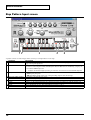
1
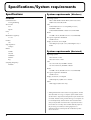
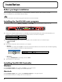
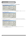
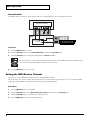
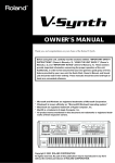
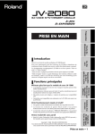
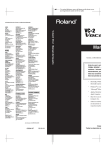
Introduction
VariOS 303 is a trial application that transforms your VariOS into a completely different sound module.
When the VariOS 303 program is installed, you can use the VariOS as an analog modeling bass synthesizer.
In addition to parameters such as cutoff and resonance, a Pattern Sequencer function is also provided.
Copyright © 2003 ROLAND CORPORATION
All rights reserved. No part of this publication may be reproduced in any form without the written permission of ROLAND
CORPORATION.
Microsoft and Windows are registered trademarks of Microsoft Corporation.
Windows® is known officially as: “Microsoft® Windows® operating system.”
Apple and Macintosh are registered trademark of Apple Computer, Inc.
MacOS is a trademark of Apple Computer, Inc.
Pentium is a registered trademark of Intel Corporation.
About this program
File structure
• VariOS 303 main program
If this program is installed in the VariOS's internal flash ROM, the VariOS can function as an analog modeling bass
synthesizer.
• VariOS 303 controller software (Windows/Macintosh)
This is editor software that lets you control the functions of the VariOS 303 from your computer.
Features
Once you have installed the program into the internal flash ROM of the VariOS, you can use a simple button operation to start up
the VariOS as the VariOS 303. Since the previous program will still remain, the normal power-on operation will start up the
VariOS with its conventional functionality.
1
Specifications/System requirements
Specifications
System requirements (Windows)
VariOS 303
Operating system:
Sound Generator:
Analog Modeling
Waveforms:
Saw
Square
Parts:
1
Maximum Polyphony:
1 voice
Patches:
128
Step Sequencer:
16 Steps
Microsoft® Windows® XP Home/XP Professional/
2000 Professional/Me/98SE
CPU:
Pentium®/Celeron™ or compatible processor,
400 MHz or better
Pentium® III 500 MHz or better is recommended
RAM:
128 MB or more (256 MB or more is recommended)
Free space required on hard disk:
30 MB or more
Display resolution/Color depth:
800 x 600 pixels, 65,536 colors (16-bit High Color) or
better
Effects:
COMP
System requirements (Macintosh)
OD/DS
CHORUS
DELAY
EQ
Sampling Frequency:
44.1kHz
Operating System:
Mac OS 9.0.4 or later
Mac OS X v10.2 or later
CPU:
OS 9: PowerPC G3, 233 MHz or better
OS X: PowerPC G3, 500 MHz or better
RAM:
192 MB or more (256 MB or more is recommended)
Free space required on hard disk:
30 MB or more
Display resolution/color depth:
800x 600 pixels, 32,000 colors or better
Other:
OMS support (Mac OS 9 only)
* Although Roland has tested numerous configurations, and has
determined that on average, a computer system similar to that
described above will permit normal operation of the VariOS 303
Controller, Roland cannot guarantee that a given computer can
be used satisfactorily with the VariOS 303 Controller based
solely on the fact that it meets the above requirements. This is
because there are too many other variables that may influence
the processing environment, including differences in
motherboard design and the particular combination of other
devices involved.
2
Names of Things and What They Do
Refer to "Names of Things and What They Do" in the "VariOS User Guide." The following points will be different when you
use VariOS 303.
Front Panel
B
C
B. PITCH/TIME/FORMANT Knobs
PITCH (C1) Knob
TIME (C2) Knob
FORMANT (C3) Knob
Adjusts the TUNING (pitch).
Adjusts the cutoff frequency.
Adjusts the resonance.
C. Indicators
TEMPO
This does not function for VariOS 303.
Rear Panel
Q
R
Q. INPUT
AUDIO IN Jacks
LEVEL Knob
GAIN switch
This does not function for VariOS 303.
This does not function for VariOS 303.
This does not function for VariOS 303.
R. OUTPUT
DIRECT OUT Jacks
This does not function for VariOS 303.
3
Installation
Before you begin installation
Before you begin, you must install the driver as described in the "Installation" chapter of the "VariOS User Guide."
If you are using Mac OS 9, install OMS and make settings.
You cannot install the VariOS 303 main program if the driver has not been installed.
Installing the VariOS 303 main program
1. Hold down the three buttons [MENU], [<CURSOR], and [VOLUME] of the VariOS, and turn on the power of it.
⇓
⇑
⇑
⇑
2. Connect your computer and the VariOS via a USB cable. The internal flash ROM of the VariOS will be detected by your
computer as a drive, and will be mounted under the drive name shown in the following table.
Windows XP
VARIOSFLASH
Other Windows versions
Removable Disk
Mac OS
VARIOSFLASH
3. From the VariOS Program folder, copy the following files to the VariOS drive that was mounted in step 2.
• VPD-02 for VariOS
• VB.prj
4. Unmount the VariOS drive that is mounted on your computer.
• Windows:
In the task tray, double-click the eject icon. Then click the item that indicates the VariOS drive (this will differ depending
on your version of Windows; see below) to unmount the drive.
fig.02-taskicon
Windows XP, 2000
Windows Me
USB high-capacity storage device
USB disk
• Macintosh:
Drag the VARIOSFLASH on the desktop into the “Trash”.
5.
Turn off the power of the VariOS.
Installing VariOS 303 Controller
Windows
In the Controller Program folder, double-click Setup to start up the installer.
Proceed with the installation according to the on-screen directions.
Macintosh
In the Controller Program folder, double-click VariOS303 Installer_E to start up the installer.
Proceed with the installation according to the on-screen directions.
4
Startup and settings
Starting up VariOS 303
1
⇓
⇑
1
⇑
2, 3
⇑
1
1. Hold down the [Menu] and [<CURSOR] buttons of the VariOS, and turn on the power.
2. Use the VariOS's [VALUE] knob to select "VPD-02."
3. Press [ENTER] ([VALUE] knob).
Starting up VariOS 303 Controller and making settings
Before you start up VariOS 303 Controller, you must connect the VariOS to your computer via a USB cable and start up VariOS
303.
If you first start up VariOS 303 Controller and then start up VariOS 303 or connect the USB cable, or if you have turned off the
power of the VariOS or disconnected the USB cable while VariOS 303 Controller is running, you must close VariOS 303 Controller
and then restart it.
1. Start up VariOS 303 Controller.
2. In the Setup menu, click Setup MIDI Devices.
3. In the VariOS Input/Output field, specify the MIDI port to which the VariOS is connected. Normally, you will select “Roland
VariOS MIDI,” as shown in the diagram.
4. If you are using a MIDI keyboard, set the Through Input field to the MIDI input port to which your MIDI keyboard is
connected. If your MIDI keyboard is connected to the VariOS, select “Roland VariOS External MIDI” as shown in the
diagram.
5
Startup and settings
5. If you’re using VariOS 303 by itself, set the Through Output field to “Roland VariOS MIDI.”
If you are using VariOS 303 with other sequencer software, set the Through Output field to “none” to prevent VariOS 303
from sounding notes in duplicate.
6. The Receive Ch field specifies VariOS 303’s MIDI receive channel. VariOS 303 will receive note-on and control change
messages on the channel you specify here. If you’ve connected a MIDI keyboard, set this channel to match the channel your
MIDI keyboard is using for transmission.
* The setting of the Receive Ch field is linked with the [Menu2 Receive Channel] setting of the VariOS hardware module.
Refer to “Setting the MIDI Receive Channel” on p. 8.
6
Basic operation
Basic operation for VariOS 303 (main unit)
Selecting patches
Turn the [VALUE] knob to select patches.
Playing from a connected keyboard (MIDI Mode)
You can connect your MIDI keyboard to the VariOS. In this case, you can change the MIDI routing (PC mode, Internal mode) in
the following ways.
PC mode
When using a USB connection, the MIDI connectors on the rear panel of the VariOS will function as a USB MIDI interface
(Roland VariOS External MIDI). When USB is not connected or when your computer is not powered up, the MIDI connectors
on the rear panel of the VariOS are connected directly to the sound generator section.
fig.042-007
Computer
When USB is
connected
Sequencer software
VariOS
Sound generator
section
When USB is
not connected
VariOS
Sound generator
section
7
Basic operation
Internal mode
The MIDI connectors of the rear panel of the VariOS are connected directly to the sound generator section.
fig.042-007a
Computer
Sequencer software
VariOS
Sound generator
section
Procedure:
1. Press the [MENU] button so it is lit.
2. Turn the [VALUE] knob to select “Menu1 MIDI Mode,” and press the [VALUE] knob.
3. Turn the [VALUE] knob to switch the setting between “Internal” or “PC.”
fig.042-0054+_75
The “PC indicator” on the front panel of the VariOS shows the current MIDI Mode status. When this is lit,
“PC” mode is selected. When dark, “Internal” mode is selected.
4. Press the [MENU] button so it is not lit.
Setting the MIDI Receive Channel
Here’s how to set the MIDI receive channel of the VariOS hardware module.
The VariOS will receive note-on and control change messages on the channel you specify here. If you’ve connected a MIDI
keyboard, set this channel to match the transmit channel of your MIDI keyboard.
Procedure:
1. Press the [MENU] button so it is lighted.
2. Turn the [VALUE] knob to select [Menu2 Receive Channel], and then press the [VALUE] knob.
3. Turn the [VALUE] knob to specify the receive channel (1–16).
4. Press the [MENU] button to turn off its illumination.
8
Basic operation
Basic operation for VariOS 303 Controller
Changing Skins
You can change the appearance of VariOS 303 by choosing [Skin] from the [Setup] menu.
Selecting a patch
To select a patch from a list, click the [LIST] button.
Editing a value
You can edit values by clicking (and dragging) buttons, sliders, or knobs. If you feel that the panel sliders or knobs are too small
for you to make detailed adjustments comfortably, try clicking (and holding) a knob and dragging the mouse farther away. You
can set the value from any position as long as you continue holding down the mouse button. When doing so, the value can be
adjusted with correspondingly greater precision as the mouse cursor is moved further away from the center of the knob.
If the value is displayed, you can also edit it by pressing your computer’s cursor keys (up/down).
9
Basic operation
Initializing a value
You can reset a parameter to its initial value by holding down the Ctrl (control) key of your computer and clicking the slider or
knob.
Renaming a patch
To rename a patch, click the [NAME] button.
Writing a patch
Click the [WRITE] button to open the Write dialog box. Select the write-destination patch number, and click the OK button.
Patches will be saved in the VariOS itself.
10
Screen reference
Main screen
2
1
3
5
4
6
7
Parameter
1 WAVEFORM
Value
SAW, SQR
2 TUNING
CUTOFF FREQ
RESONANCE
ENV MOD
-63–+63
0–127
0–127
0–127
DECAY
0–127
ACCENT
3 NAME
LIST
4 SYNC
0–127
—
—
INT, MIDI
TEMPO
5 PATTERN
MODE
20–250
1–6
STEP, SLIDER,
EFFECT
0–127
—
6 VOLUME
READ
MASTER TUNE
7 WRITE
RUN/STOP
Description
Switches between the two audio source waveforms.
SAW: Sawtooth wave
SQR: Square wave
Adjusts the pitch in a range of one octave up or down.
Sets the cutoff frequency of the filter.
Sets the resonance.
Specifies the depth of the envelope. Higher settings will cause the envelope to produce
greater change.
Specifies the decay time of the envelope (the time from when the envelope level reaches the maximum value until it falls to a constant value).
Adjusts the strength of the accent programmed into the bass pattern.
Refer to p. 10.
Refer to p. 9.
Determines the clock to which the pattern tempo is to be synchronized.
INT: Synchronize to the patch tempo.
MIDI: Synchronize to the clock of the external sequencer. (Refer to p. 16)
Sets the tempo of the pattern.
Six patterns can be stored for each patch.
Switches the edit screens.
415.3–466.2 Hz
Adjusts the volume.
Loads settings from the VariOS 303 into VariOS 303 controller so that the Controller
screen matches the settings of the unit itself.
Click MASTER TUNE to display the Tune dialog box.
—
—
Adjusts the overall tuning. The display of 440 Hz shows the frequency of the A4 note
(center A).
Saves the patch.
Plays/stops the pattern.
11
Screen reference
Step Pattern Input screen
6
1 2
3
4
5
A pattern consists of sixteen steps. In this screen you can input data for each step.
Parameter
1 PTN ON/OFF
2 PTN SHIFT
3 C–B, TIE
4 OCTAVE SHIFT DOWN
OCTAVE SHIFT UP
5 ACCENT
SLIDE
MUTE
6 BACK
NEXT
12
Description
Note-on messages from an external MIDI keyboard can be used to play patterns. Note-off messages will stop the playback.
Shifts the key (transposes the pitch) of the phrase you programmed for the pattern. This setting
is relative to C4. The pitch will be shifted by the distance between C4 and the key you play on
your external MIDI keyboard.
* A shift is not obtained simply by clicking a C–B button. You must use an external MIDI keyboard.
These input notes.
C–B: Specify the pitch.
TIE: Extend the length of the note of the preceding step into the current step.
Lowers the note pitch by one octave.
Raises the note pitch by one octave.
Switches the accent (p. 11) on/off.
If this is on, the pitch will change smoothly between the preceding note and the current note.
If this is on, the sound will be muted (silenced).
Moves backward one step. The STEP indication will move by -1.
Moves forward by one step. The STEP indication will move by +1.
Screen reference
Slider Pattern Input screen
1
2
3
4
A pattern consists of sixteen steps. In this screen you can input all sixteen steps simultaneously.
Parameter
1 ACCENT
SLIDE
2 NOTE, TIE
3 OCTAVE SHIFT DOWN
OCTAVE SHIFT UP
4 MUTE
Description
Switches the accent (p. 11) on/off.
If this is on, the pitch will change smoothly between the preceding note and the current note.
These input notes.
C–B: Specify the pitch.
TIE: Extend the length of the note of the preceding step into the current step.
Lowers the note pitch by one octave.
Raises the note pitch by one octave.
If this is on, the sound will be muted (silenced).
13
Screen reference
Effect screen
Bass Multi provides Comp/Limiter, Overdrive or Distortion, 3-band equalizer, Chorus or Flanger, and Delay effects connected in series. This
algorithm is a multi-effects for bass.
1
2
3
4
5
1. COMP
Parameter
COMP
RATIO
GAIN
THRES
ATTACK
RELEASE
Value
OFF, ON
1.5:1, 2:1, 4:1, 100:1
-60– +12 dB
-60–0 dB
0–127
0–127
Description
Turns the comp/limiter on/off.
Sets the “source sound:output sound” compression ratio.
Adjusts the output gain.
Sets the volume level at which the compression begins.
Sets the time after the sound volume is crossed the value of THRES until compression begins.
Specifies the time from when the volume drops below the value of THRES until compression is
no longer applied.
2. OD/DS
Parameter
OD/DS
DRIVE MODE
DRIVE
Value
OFF, ON
OD, DS
0–127
Description
Selects whether to use overdrive or distortion.
Selects whether to use overdrive (OD) or distortion (DS).
Degree of distortion
3. EQUALIZER
Parameter
LOW FREQ
MID FREQ
HIGH FREQ
LOW GAIN
MID GAIN
HIGH GAIN
14
Value
50–4000 Hz
50–20000 Hz
2000–20000 Hz
-15– +15 dB
-15– +15 dB
-15– +15 dB
Description
Frequency of the low range
Frequency of the middle range
Frequency of the high range
Gain of the low range
Gain of the middle range
Gain of the high range
Screen reference
4. CHORUS
Parameter
CHORUS MODE
RATE
MOD LEVEL
DEPTH
FEEDBACK
Value
CHO, FLNG
0.05–10.0 Hz
0–127
0–127
-98– +98 %
Description
Selects whether to use chorus or flanger.
Adjusts the speed of modulation for the chorus or flanger.
Volume of the chorus or flanger sound.
Adjusts the depth of modulation for the chorus or flanger.
Adjusts the proportion of the effect sound that is fed back into the effect. Negative (-) settings
will invert the phase.
5. DELAY
This is a stereo delay. Depending on the length of the delay you set, you can get long echoes, thick sounds, or spatial sounds.
Parameter
DELAY
TIME
BALANCE
LEVEL
FEEDBACK
Value
OFF, ON
0–1300 ms
DRY100:0WET–DRY0:100WET
0–127
-98– +98 %
Description
Switches the delay on/off.
Adjusts the delay time from the direct sound until the delay sound is heard.
Volume balance between the direct sound (DRY) and the delay sound (WET)
Adjusts the amount of delay.
Adjusts the proportion of the delay sound that is fed back into the effect. Negative (-) settings will invert the phase.
15
Cautions when using VariOS 303 with
another sequencer
Synchronizing the step sequencer to the tempo of your MIDI
sequencer
If you are using VariOS 303 with your MIDI sequencer, you can set VariOS 303 Controller's [SYNC] switch to MIDI so that the
VariOS 303 step sequencer will be synchronized to the tempo of your MIDI sequencer.
1. Set VariOS 303 Controller's [SYNC] switch to MIDI. (Refer to p. 11)
2. Start up your MIDI sequencer.
3. Send the MIDI clock of your MIDI sequencer to “Roland VariOS MIDI” (the port of the VariOS sound generator section).
4. Specify Roland VariOS MIDI (the port of the VariOS sound generator section) as the output port for the tracks of your
sequencer, so that it will control the VariOS.
About MIDI channels
When playing VariOS 303 from a sequencer, choose Roland VariOS MIDI as the output port for the corresponding track in your
sequencer, and set the MIDI output channel to match the MIDI Receive Channel of the VariOS. You can use either of the following
two methods to set the VariOS’s MIDI Receive Channel.
• From VariOS 303 Controller
Refer to step 6 of “Starting up VariOS 303 Controller and making settings” on p. 6.
• From the menu of the VariOS hardware module
Refer to “Setting the MIDI Receive Channel” on p. 8.
16
Starting up VariOS 303 from a PC card
The VariOS trial applications "VariOS-8" and "VariOS 303" can be copied to a PC card, so that the programs can be started up from
a PC card inserted in the VariOS.
This is very convenient, since you can start up a VariOS trial application simply by inserting the PC card into the card slot of the
VariOS and turning the power on. (If you have copied more than one trial application onto the PC card, you can use the [VALUE]
knob at start-up to switch applications.)
You will need a PC card (sold separately) in order to do this.
If you use a PC card, be sure that it meets the requirements given in "Using PC Cards" (p. 5) of the "VariOS User Guide."
When using a PC card, you must format it on the VariOS itself using the procedure described in the "VariOS User Guide" section
"VariOS Menu Reference" -> "8-5 Format."
Installation
If your computer does not have a PC card reader
First use the "Installation" (p. 4) procedure described in this manual to copy VB.prj to the internal flash ROM of the VariOS.
1. Make sure that a PC card is not inserted in the PC card slot of the VariOS. Then use a USB cable to connect the VariOS to your
computer, and start up the computer.
2. Hold down the [MENU], [<CURSOR], and [ENTER] ([VALUE] knob) buttons of the VariOS, and turn on the power of it.
3. Insert the PC card into the PC card slot of the VariOS.
4. The PC card inserted in the VariOS will be recognized by your computer as a drive, and will be mounted as the drive name
shown in the following table.
Windows 98SE, Me, 2000 Removable Disk
Windows XP, Macintosh
PC CARD
5. From the VariOS Program folder, drag VPD-02 for VariOS.BIN to copy it into the PC card drive.
6. Rename the copied file VPD-02 for VariOS.BIN as follows. (Change the third character from "D" to "I" (the uppercase letter "I";
not the numeral "one").
VPD-02 for VariOS.BIN
↓
VPI-02 for VariOS.BIN
17
Starting up VariOS 303 from a PC card
7. Unmount the PC card drive that is mounted on your computer.
• Windows:
In the task tray, double-click the eject icon. Then click the item that indicates the PC card drive (this will differ depending
on your version of Windows; see below) to unmount the drive.
fig.02-taskicon
Windows XP, 2000
Windows Me
USB high-capacity storage device
USB disk
• Macintosh:
Drag the PC CARD on the desktop into the “Trash”.
* The PC CARD you dragged into the Recycle Bin will be mounted again, but this is not a problem.
8.
Turn off the power of the VariOS.
This completes the installation. Refer to "Usage," below.
If your computer has a PC card reader
First use the "Installation" (p. 4) procedure described in this manual to copy VB.prj to the internal flash ROM of the VariOS.
1. Start up your computer, and insert the PC card into the PC card reader.
2. From the VariOS Program folder, drag VPD-02 for VariOS.BIN to copy it into the PC card drive.
3. Rename the copied file VPD-02 for VariOS.BIN as follows. (Change the third character from "D" to "I" (the uppercase letter "I";
not the numeral "one").
VPD-02 for VariOS.BIN
↓
VPI-02 for VariOS.BIN
4. Unmount the PC card drive that is mounted on your computer.
This completes the installation. Refer to "Usage," below.
Usage
1. When you insert the PC card into the VariOS and power-on the VariOS, the VariOS trial application that was written to the PC
card will start up.
If you want to start up the internal program of the VariOS, remove the PC card and power-on the VariOS.
2. If you have copied more than one trial application to the PC card, the display will indicate "Select Program" when the VariOS
starts up. Turn the [VALUE] knob to select the desired application, and press [ENTER] to start up.
If the patch name does not appear (i.e., displayed as "001:
"), the VariOS's internal flash ROM does not contain patch
data. Copy VB.prj into the VariOS's internal flash ROM as described in "Installation" (p. 4).
18
MIDI Implementation
System Exclusive Message
Parameter Address Map
●Data Transmission
*
This instrument can use exclusive messages to exchange many varieties of internal settings
with other devices.
The model ID of the exclusive messages used by this instrument is 00H 6DH.
❍Data Request 1RQ1 (11H)
This message requests the other device to transmit data. The address and size indicate the
type and amount of data that is requested.
When a Data Request message is received, if the device is in a state in which it is able to
transmit data, and if the address and size are appropriate, the requested data is transmitted
as a Data Set 1 (DT1) message. If the conditions are not met, nothing is transmitted.
Status
F0H
Byte
F0H
41H
10H
00H
6DH
11H
aaH
bbH
ccH
ddH
ssH
ttH
uuH
vvH
sum
F7H
*
data byte
status
41H, dev, 00H, 53H, 11H, aaH, bbH, ccH, F7H
ddH, ssH, ttH, uuH, vvH, sum
Transmission of “#” marked address is divided to some packets. For example, ABH in
hexadecimal notation will be divided to 0AH and 0BH, and is sent/received in this
order.
■VariOS 303 (ModelID = 00H 6DH)
+------------------------------------------------------------------------------+
| Start
|
|
|
Address |
Description
|
|-------------+----------------------------------------------------------------|
| 01 00 00 00 | Setup
|
|-------------+----------------------------------------------------------------|
| 10 00 00 00 | Temporary Patch
|
|-------------+----------------------------------------------------------------|
| 20 00 00 00 | User Patch (001)
|
| 20 01 00 00 | User Patch (002)
|
|
: |
|
| 20 7F 00 00 | User Patch (128)
|
+------------------------------------------------------------------------------+
❍Patch
+------------------------------------------------------------------------------+
| Offset
|
|
|
Address |
Description
|
|-------------+----------------------------------------------------------------|
|
00 10 00 | Patch Common
|
|
00 11 00 | Patch Effect
|
|
00 12 00 | Patch Tone
|
|
00 13 00 | Patch Pattern 1
|
|
00 14 00 | Patch Pattern 2
|
|
00 15 00 | Patch Pattern 3
|
|
00 16 00 | Patch Pattern 4
|
|
00 17 00 | Patch Pattern 5
|
|
00 18 00 | Patch Pattern 6
|
+------------------------------------------------------------------------------+
Remarks
Exclusive status
ID number (Roland)
device ID
model ID #1 (VariOS 303)
model ID #2 (VariOS 303)
command ID (RQ1)
address MSB
address
address
address LSB
size MSB
size
size
size LSB
checksum
EOX (End Of Exclusive)
❍Setup
The size of data that can be transmitted at one time is fixed for each type of data. And
data requests must be made with a fixed starting address and size. Refer to the address
and size given in “Parameter Address Map.”
+------------------------------------------------------------------------------+
| Offset
|
|
|
Address |
Description
|
|-------------+----------------------------------------------------------------|
|
00 00 | 0aaa aaaa | Part 1 Bank Select MSB (CC# 0)
(0 - 127) |
|
00 01 | 0aaa aaaa | Part 1 Bank Select LSB (CC# 32)
(0 - 127) |
|
00 02 | 0aaa aaaa | Part 1 Program Number (PC)
(0 - 127) |
|#
00 03 | 0000 aaaa |
|
|
| 0000 bbbb |
|
|
| 0000 cccc |
|
|
| 0000 dddd | Master Tune
(24 - 2024) |
|
|
|
-100.0 - +100.0 [cent] |
|
00 07 | 0000 000a | Clock Source
(0 - 1) |
|
|
|
INT, MIDI |
|
00 08 | 0000 aaaa | Receive Channel
(0 - 15) |
|
|
|
1 - 16 |
|-------------+-----------+----------------------------------------------------|
| 00 00 00 09 | Total Size
|
+------------------------------------------------------------------------------+
❍Patch Common
❍Data Set 1
DT1 (12H)
Status
F0H
Data byte
41H, dev, 00H, 53H, 12H, aaH, bbH,
ccH, ddH, eeH, ... ffH, sum
Byte
F0H
41H
10H
00H
6DH
12H
aaH
bbH
Explanation
Exclusive status
ID number (Roland)
Device ID
Model ID #1 (VariOS 303)
Model ID #2 (VariOS 303)
Command ID (DT1)
Address MSB: upper byte of the starting address of the data to be sent
Address: upper middle byte of the starting address of the data to be
sent
Address: lower middle byte of the starting address of the data to be
ccH
sent
ddH
eeH
:
ffH
sum
F7H
*
*
Status
F7H
Address LSB: lower byte of the starting address of the data to be sent.
Data: the actual data to be sent. Multiple bytes of data are transmitted
in order starting from the address.
:
Data
Checksum
EOX (End Of Exclusive)
The amount of data that can be transmitted at one time depends on the type of data, and
data will be transmitted from the specified starting address and size. Refer to the address
and size given in “Parameter Address Map.”
Data larger than 256 bytes will be divided into packets of 256 bytes or less, and each
packet will be sent at an interval of about 20 ms.
+------------------------------------------------------------------------------+
| Offset
|
|
|
Address |
Description
|
|-------------+----------------------------------------------------------------|
|
00 00 | 0aaa aaaa | Patch Name 1
(32 - 127) |
|
|
|
32 - 127 [ASCII] |
|
00 01 | 0aaa aaaa | Patch Name 2
(32 - 127) |
|
|
|
32 - 127 [ASCII] |
|
00 02 | 0aaa aaaa | Patch Name 3
(32 - 127) |
|
|
|
32 - 127 [ASCII] |
|
00 03 | 0aaa aaaa | Patch Name 4
(32 - 127) |
|
|
|
32 - 127 [ASCII] |
|
00 04 | 0aaa aaaa | Patch Name 5
(32 - 127) |
|
|
|
32 - 127 [ASCII] |
|
00 05 | 0aaa aaaa | Patch Name 6
(32 - 127) |
|
|
|
32 - 127 [ASCII] |
|
00 06 | 0aaa aaaa | Patch Name 7
(32 - 127) |
|
|
|
32 - 127 [ASCII] |
|
00 07 | 0aaa aaaa | Patch Name 8
(32 - 127) |
|
|
|
32 - 127 [ASCII] |
|
00 08 | 0aaa aaaa | Patch Name 9
(32 - 127) |
|
|
|
32 - 127 [ASCII] |
|
00 09 | 0aaa aaaa | Patch Name 10
(32 - 127) |
|
|
|
32 - 127 [ASCII] |
|
00 0A | 0aaa aaaa | Patch Name 11
(32 - 127) |
|
|
|
32 - 127 [ASCII] |
|
00 0B | 0aaa aaaa | Patch Name 12
(32 - 127) |
|
|
|
32 - 127 [ASCII] |
|-------------+-----------+----------------------------------------------------|
|
00 0C | 0aaa aaaa | (reserved)
(0 - 127) |
|-------------+-----------+----------------------------------------------------|
|#
00 0D | 0000 aaaa |
|
|
| 0000 bbbb | Patch Tempo
(20 - 250) |
|
|
|
20 - 250 |
|-------------+-----------+----------------------------------------------------|
|
00 0F | 00aa aaaa | Pitch Bend Range Up
(0 - 48) |
|
00 10 | 00aa aaaa | Pitch Bend Range Down
(0 - 48) |
|
00 11 | 0000 000a | Delay Switch
(0 - 1) |
|
|
|
OFF, ON |
|-------------+-----------+----------------------------------------------------|
|
00 12 | 0000 000a | Pattern Status
(0 - 2) |
|
|
|
OFF, ON, RUN |
|
00 13 | 0000 0aaa | Pattern Select
(0 - 5) |
|
|
|
1 - 6 |
|
00 14 | 0000 000a | Pattern Shift
(0 - 1) |
|
|
|
OFF, ON |
|
00 15 | 0aaa 0aaa | (reserved)
(0 - 127) |
|
00 16 | 0aaa aaaa | (reserved)
(0 - 127) |
|
00 17 | 0aaa aaaa | (reserved)
(0 - 127) |
|-------------+----------------------------------------------------------------|
| 00 00 00 18 | Total Size
|
+------------------------------------------------------------------------------+
19
MIDI Implementation
❍Patch Effect
❍Patch Pattern
+------------------------------------------------------------------------------+
| Offset
|
|
|
Address |
Description
|
|-------------+----------------------------------------------------------------|
|
00 00 | 0aaa aaaa | Delay Send Level
(0 - 127) |
|
00 01 | 0aaa aaaa | (reserved)
(0 - 127) |
|
00 02 | 0aaa aaaa | (reserved)
(0 - 127) |
|
00 03 | 0aaa aaaa | (reserved)
(0 - 127) |
|
00 04 | 0aaa aaaa | (reserved)
(0 - 127) |
|
00 05 | 0aaa aaaa | (reserved)
(0 - 127) |
|
00 06 | 0aaa aaaa | (reserved)
(0 - 127) |
|
00 07 | 0aaa aaaa | (reserved)
(0 - 127) |
|
00 08 | 0aaa aaaa | (reserved)
(0 - 127) |
|
00 09 | 0aaa aaaa | (reserved)
(0 - 127) |
|
00 0A | 0aaa aaaa | (reserved)
(0 - 127) |
|
00 0B | 0aaa aaaa | (reserved)
(0 - 127) |
|
00 0C | 0aaa aaaa | (reserved)
(0 - 127) |
|
00 0D | 0aaa aaaa | (reserved)
(0 - 127) |
|
00 0E | 0aaa aaaa | (reserved)
(0 - 127) |
|
00 0F | 0aaa aaaa | (reserved)
(0 - 127) |
|-------------+-----------+----------------------------------------------------|
|
00 10 | 0000 000a | Comp Sw
(0 - 1) |
|
|
|
OFF, ON |
|
00 11 | 0000 00aa | Comp Ratio
(0 - 3) |
|
00 12 | 00aa aaaa | Comp Threshold
(0 - 60) |
|
00 13 | 0aaa aaaa | Comp Attack
(0 - 127) |
|
00 14 | 0aaa aaaa | Comp Release
(0 - 127) |
|
00 15 | 0aaa aaaa | Comp Gain
(0 - 72) |
|
00 16 | 0000 000a | Distortion Sw
(0 - 1) |
|
|
|
OFF, ON |
|
00 17 | 0000 000a | Distortion Mode
(0 - 1) |
|
|
|
OD, DS |
|
00 18 | 0aaa aaaa | Drive
(0 - 127) |
|
00 19 | 000a aaaa | EQ Low Freq
(0 - 19) |
|
00 1A | 000a aaaa | EQ Low Gain
(0 - 30) |
|
00 1B | 000a aaaa | EQ Mid Freq
(0 - 26) |
|
00 1C | 000a aaaa | EQ Mid Gain
(0 - 30) |
|
00 1D | 0000 aaaa | EQ High Freq
(0 8) |
|
00 1E | 000a aaaa | EQ High Gain
(0 - 30) |
|
00 1F | 0000 000a | Chorus Mode
(0 - 1) |
|
|
|
CHORUS, FLANGER |
|
00 20 | 0aaa aaaa | Chorus Rate
(0 - 111) |
|
00 21 | 0aaa aaaa | Chorus Depth
(0 - 127) |
|
00 22 | 0aaa aaaa | Chorus Feedbk
(0 - 98) |
|
00 23 | 0aaa aaaa | Chorus Level
(0 - 127) |
|
00 24 | 0aaa aaaa | (reserved)
(0 - 127) |
|
00 25 | 0aaa aaaa | (reserved)
(0 - 127) |
|
00 26 | 0aaa aaaa | (reserved)
(0 - 127) |
|
00 27 | 0aaa aaaa | (reserved)
(0 - 127) |
|
00 28 | 0aaa aaaa | (reserved)
(0 - 127) |
|
00 29 | 0aaa aaaa | (reserved)
(0 - 127) |
|-------------+-----------+----------------------------------------------------|
|
00 2A | 0aaa aaaa | DELAY Time
(0 - 105) |
|
00 2B | 0aaa aaaa | DELAY Balance
(0 - 100) |
|
00 2C | 0aaa aaaa | DELAY Feedbk
(0 - 98) |
|
00 2D | 0aaa aaaa | (reserved)
(0 - 127) |
|
00 2E | 0aaa aaaa | (reserved)
(0 - 127) |
|
00 2F | 0aaa aaaa | (reserved)
(0 - 127) |
|-------------+----------------------------------------------------------------|
| 00 00 00 30 | Total Size
|
+------------------------------------------------------------------------------+
+------------------------------------------------------------------------------+
| Offset
|
|
|
Address |
Description
|
|-------------+----------------------------------------------------------------|
|
00 00 | 0000 aaaa | Step 1 Note
(0 - 12) |
|
00 01 | 0000 aaaa | Step 2 Note
(0 - 12) |
|
00 02 | 0000 aaaa | Step 3 Note
(0 - 12) |
|
00 03 | 0000 aaaa | Step 4 Note
(0 - 12) |
|
00 04 | 0000 aaaa | Step 5 Note
(0 - 12) |
|
00 05 | 0000 aaaa | Step 6 Note
(0 - 12) |
|
00 06 | 0000 aaaa | Step 7 Note
(0 - 12) |
|
00 07 | 0000 aaaa | Step 8 Note
(0 - 12) |
|
00 08 | 0000 aaaa | Step 9 Note
(0 - 12) |
|
00 09 | 0000 aaaa | Step 10 Note
(0 - 12) |
|
00 0A | 0000 aaaa | Step 11 Note
(0 - 12) |
|
00 0B | 0000 aaaa | Step 12 Note
(0 - 12) |
|
00 0C | 0000 aaaa | Step 13 Note
(0 - 12) |
|
00 0D | 0000 aaaa | Step 14 Note
(0 - 12) |
|
00 0E | 0000 aaaa | Step 15 Note
(0 - 12) |
|
00 0F | 0000 aaaa | Step 16 Note
(0 - 12) |
|-------------+-----------+----------------------------------------------------|
|
00 10 | 0000 000a | Step 1 Slide
(0 1) |
|
00 11 | 0000 000a | Step 2 Slide
(0 1) |
|
00 12 | 0000 000a | Step 3 Slide
(0 1) |
|
00 13 | 0000 000a | Step 4 Slide
(0 1) |
|
00 14 | 0000 000a | Step 5 Slide
(0 1) |
|
00 15 | 0000 000a | Step 6 Slide
(0 1) |
|
00 16 | 0000 000a | Step 7 Slide
(0 1) |
|
00 17 | 0000 000a | Step 8 Slide
(0 1) |
|
00 18 | 0000 000a | Step 9 Slide
(0 1) |
|
00 19 | 0000 000a | Step 10 Slide
(0 1) |
|
00 1A | 0000 000a | Step 11 Slide
(0 1) |
|
00 1B | 0000 000a | Step 12 Slide
(0 1) |
|
00 1C | 0000 000a | Step 13 Slide
(0 1) |
|
00 1D | 0000 000a | Step 14 Slide
(0 1) |
|
00 1E | 0000 000a | Step 15 Slide
(0 1) |
|
00 1F | 0000 000a | Step 16 Slide
(0 1) |
|-------------+-----------+----------------------------------------------------|
|
00 20 | 0000 00aa | Step 1 Octave
(0 2) |
|
00 21 | 0000 00aa | Step 2 Octave
(0 2) |
|
00 22 | 0000 00aa | Step 3 Octave
(0 2) |
|
00 23 | 0000 00aa | Step 4 Octave
(0 2) |
|
00 24 | 0000 00aa | Step 5 Octave
(0 2) |
|
00 25 | 0000 00aa | Step 6 Octave
(0 2) |
|
00 26 | 0000 00aa | Step 7 Octave
(0 2) |
|
00 27 | 0000 00aa | Step 8 Octave
(0 2) |
|
00 28 | 0000 00aa | Step 9 Octave
(0 2) |
|
00 29 | 0000 00aa | Step 10 Octave
(0 2) |
|
00 2A | 0000 00aa | Step 11 Octave
(0 2) |
|
00 2B | 0000 00aa | Step 12 Octave
(0 2) |
|
00 2C | 0000 00aa | Step 13 Octave
(0 2) |
|
00 2D | 0000 00aa | Step 14 Octave
(0 2) |
|
00 2E | 0000 00aa | Step 15 Octave
(0 2) |
|
00 2F | 0000 00aa | Step 16 Octave
(0 2) |
|-------------+-----------+----------------------------------------------------|
|
00 30 | 0000 000a | Step 1 Accent
(0 1) |
|
00 31 | 0000 000a | Step 2 Accent
(0 1) |
|
00 32 | 0000 000a | Step 3 Accent
(0 1) |
|
00 33 | 0000 000a | Step 4 Accent
(0 1) |
|
00 34 | 0000 000a | Step 5 Accent
(0 1) |
|
00 35 | 0000 000a | Step 6 Accent
(0 1) |
|
00 36 | 0000 000a | Step 7 Accent
(0 1) |
|
00 37 | 0000 000a | Step 8 Accent
(0 1) |
|
00 38 | 0000 000a | Step 9 Accent
(0 1) |
|
00 39 | 0000 000a | Step 10 Accent
(0 1) |
|
00 3A | 0000 000a | Step 11 Accent
(0 1) |
|
00 3B | 0000 000a | Step 12 Accent
(0 1) |
|
00 3C | 0000 000a | Step 13 Accent
(0 1) |
|
00 3D | 0000 000a | Step 14 Accent
(0 1) |
|
00 3E | 0000 000a | Step 15 Accent
(0 1) |
|
00 3F | 0000 000a | Step 16 Accent
(0 1) |
|-------------+-----------+----------------------------------------------------|
|
00 40 | 0000 000a | Step 1 Mute
(0 1) |
|
00 41 | 0000 000a | Step 2 Mute
(0 1) |
|
00 42 | 0000 000a | Step 3 Mute
(0 1) |
|
00 43 | 0000 000a | Step 4 Mute
(0 1) |
|
00 44 | 0000 000a | Step 5 Mute
(0 1) |
|
00 45 | 0000 000a | Step 6 Mute
(0 1) |
|
00 46 | 0000 000a | Step 7 Mute
(0 1) |
|
00 47 | 0000 000a | Step 8 Mute
(0 1) |
|
00 48 | 0000 000a | Step 9 Mute
(0 1) |
|
00 49 | 0000 000a | Step 10 Mute
(0 1) |
|
00 4A | 0000 000a | Step 11 Mute
(0 1) |
|
00 4B | 0000 000a | Step 12 Mute
(0 1) |
|
00 4C | 0000 000a | Step 13 Mute
(0 1) |
|
00 4D | 0000 000a | Step 14 Mute
(0 1) |
|
00 4E | 0000 000a | Step 15 Mute
(0 1) |
|
00 4F | 0000 000a | Step 16 Mute
(0 1) |
|-------------+----------------------------------------------------------------|
| 00 00 00 50 | Total Size
|
+------------------------------------------------------------------------------+
❍Patch Tone
+------------------------------------------------------------------------------+
| Offset
|
|
|
Address |
Description
|
|-------------+-----------+----------------------------------------------------|
|
00 00 | 0000 aaaa | Waveform
(0 1) |
|
|
|
SAW, SQUARE |
|
00 01 | 0aaa aaaa | Tuning
(1 - 127) |
|-------------+-----------+----------------------------------------------------|
|
00 02 | 0aaa aaaa | Cutoff Freq
(0 - 127) |
|
00 03 | 0aaa aaaa | Resonance
(0 - 127) |
|
00 04 | 0aaa aaaa | Env Mod
(0 - 127) |
|
00 05 | 0aaa aaaa | Decay
(0 - 127) |
|
00 06 | 0aaa aaaa | Accent
(0 - 127) |
|
00 07 | 0aaa aaaa | Volume
(0 - 127) |
|-------------+----------------------------------------------------------------|
| 00 00 00 08 | Total Size
|
+------------------------------------------------------------------------------+
20
MIDI Control Change Table
VariOS 303
MIDI Control#
0
1
2
3
4
5
6
7
8
9
10
11
12
13
14
15
16
17
18
19
20
21
22
23
24
25
26
27
28
29
30
31
32
33
34
35
36
37
38
39
40
41
42
43
44
45
46
47
48
49
50
51
52
53
54
55
56
57
58
59
MIDI Controller Name
Bank Select MSB
Modulation
Breath Type
Foot Type
Portament Time
Data Entry MSB
Volume
Balance
Pan
Expression
General Purpose Controller 1 MSB
General Purpose Controller 2 MSB
General Purpose Controller 3 MSB
General Purpose Controller 4 MSB
Bank Select LSB
Modulation LSB
Breath Type LSB
Foot Type LSB
Portamento Time LSB
Data Entry LSB
Volume LSB
Balance LSB
Pan LSB
Expression LSB
Parameter Name
Range
(Modulation)
Tuning
Cutoff Freq
Resonance
1–127
0–127
0–127
(Part Volume)
Env Mod
Decay
0–127
0–127
(Part Expression)
Accent
Volume
Patch Tempo
Pattern Status
Pattern Select
Pattern Shift
Waveform
Comp Sw
Comp Ratio
Comp Threshold
Comp Attack
Comp Release
Comp Gain
OD/DS Sw
Drive Mode
Drive
EQ Low Freq
EQ Low Gain
EQ Mid Freq
EQ Mid Gain
0–127
0–127
10–125
0–2
0–5
0–1
0–1
0–1
0–3
0–60
0–127
0–127
0–72
0–1
0–1
0–127
0–19
0–30
0–26
0–30
EQ Hi Freq
EQ Hi Gain
Chorus Mode
Chorus Rate
Chorus MOD Level
0–8
0–30
0–1
0–111
0–127
Chorus Depth
Chorus Feedback
Delay Switch
Delay Time
Delay Level
Delay Balance
Delay Feedback
0–127
0–98
0–1
0–105
0–127
0–100
0–98
General Purpose Controller 1 LSB
General Purpose Controller 2 LSB
General Purpose Controller 3 LSB
General Purpose Controller 4 LSB
21
MIDI Control Change Table
MIDI Control# MIDI Controller Name
Parameter Name
60
61
62
63
64
Hold 1
(Hold)
65
Portamento
66
Sostenuto
(Sostenuto)
67
Soft
68
Legato Foot Switch
69
Hold 2
70
Sound Controller1
71
Sound Controller2
72
Sound Controller3
73
Sound Controller4
74
Sound Controller5
75
Sound Controller6
76
Sound Controller7
77
Sound Controller8
78
Sound Controller9
79
Sound Controller10
80
General Purpose Controller 5
81
General Purpose Controller 6
82
General Purpose Controller 7
83
General Purpose Controller 8
84
Portamento Control
85
86
87
88
89
90
91
Reverb
(Part Delay Send Level)
92
Tremolo
93
Chorus
(Part Chorus Send Level)
94
Seleste
95
Phaser
96
Data Increment
97
Data Decrement
98
NRPN LSB
99
NRPN MSB
100
RPN LSB
101
RPN MSB
102
103
104
105
106
107
108
109
110
111
112
113
114
115
116
117
118
119
* Parameters shown in parentheses ( ) cannot be edited using VariOS 303 Controller.
22
Range