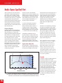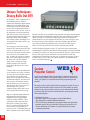
1
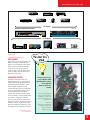
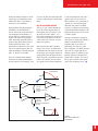
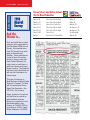
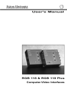
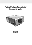
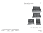
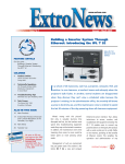
JANUARY/FEBRUARY 1999
VOLUME 10
NUMBER 1
The Matrix 6400 Video System:
Unrivaled Simplicity and Flexibility
Sixty-four signals in a single site—an
installer’s nightmare; a cable seller’s
dream-come-true. Computers, monitors,
projectors, cameras, VCRs, video
receivers, DVD, audio, and who knows
what else, all in close proximity and in
dire need of some kind of centralized
control. Does this sound familiar? Does
your latest installation use a number of
different signal types? Do you need to
distribute a large amount of signals as
well as route them? If so, then the Matrix
6400 series switchers are exactly what
you need.
The Matrix 6400 series includes
wideband/RGB, sync, audio, and video
models. The Matrix 6400 Video model is
a true 64 x 64 matrix with 80 MHz (-3dB)
of video bandwidth, fully loaded. It is
capable of 132 presets (32 global, 100
rooming) and will switch component,
S-Video, and composite signals, making it
perfect for a large variety of A/V applications, including use with
HDTV. In addition, it features gen-locking for smooth transitions
between signal selection, non-volatile memory to make sure presets
are never lost, and a host of optional features such as an internal
redundant power supply, the MKP-1000 remote keypad, and our
highly intuitive FPC-1000 LCD front panel controller. But the
Matrix 6400 is more than just a switcher, it is a system that is
modular, field-upgradeable and expandable.
While each Matrix 6400 Video model comes standard with 64
inputs, it may be purchased with fewer outputs. This is made
(continued on page 2– See “Matrix 6400”)
Economy and Versatility:
Extron’s Matrix 50 Series Switcher
With hundreds of items available for the
audio/visual professional, Extron occasionally finds that a truly superior
product gets overlooked. The Matrix 50
Series Switcher is just that—one of our
most flexible and economic products
that every system designer should be
familiar with.
One word sums up the Matrix 50:
Versatility. Video configurations include
models for Composite video, S-Video,
and Component video (including RGsB)
at 80 MHz, with four available
input/output sizes: 12 x 8, 12 x 4, 8 x 8,
or 8 x 4. Balanced or unbalanced twochannel audio switching is available in
the same sizes with any of these choices
or by itself without any video capabilities. Altogether, this gives the Matrix 50
Series Switcher 28 possible configurations, providing solutions for numerous
applications.
(continued on page 3– See “Matrix 50”)
In This Issue:
RGB 406 & RGB 440: Architectural Power ............4
NTSC Decoding Basics (Part II) ............................5
New Products....................................................6
Tech Corner....................................................12
New News ......................................................14
Audio Specs Spelled Out ..................................16
Unique Techniques ........................................18
Web Tip ..........................................................18
CEDIA Regional Educational Program ..............19
EXTRONEWS JAN/FEB 1999
Matrix 6400 –
continued from page 1
possible by the use of removable video output
boards, each with eight outputs (see Figure 1).
The Matrix 6400 Video model may be ordered
with as few as one of these boards, and
remains expandable with additional fieldinstallable boards available at any time. A full
complement of eight video output boards
would allow for a 64 x 64 configuration with
composite signals, 32 x 32 with S-Video, or 21
x 21 with component, as well as numerous
combinations of the three different signals, all
within the same matrix switcher. As your
system grows, so will your Matrix 6400 Video
model switcher.
But just how far will it grow? Each Matrix 6400
Video model is capable of communicating with
up to two additional BMEs (Basic Module
Enclosures), which are then all controlled by the
same RS-232 port. This arrangement is
commonly used to break up the individual parts
of an S-Video or component video signal,
although combinations of S-Video, and
component are possible as well. For example,
with S-Video, a pairing of two Matrix 6400
Video models would have one switcher routing
the Y channel (luminance), and the other
handling the C channel (chrominance). With
component video signals, one switcher could be
used for the Y channel, another for the B-Y,
and a third for the R-Y (see Figure 1). The
result is that two Matrix 6400 Video models
will switch 64 x 64 S-Video signals, or
32 x 32 with component video. With a third
switcher the system can coordinate the impressive total of 64 input and 64 output component
video signals. Add a Matrix 6400 Audio model
to the rack, and you can have as many as four
Matrix 6400s operating together as a true A/V
matrix switching system. Like the video
output boards, additional switchers may be
interconnected at any time, without any
factory configuration.
(continued on page 19– See “Matrix 6400”)
ExtroNews™
Managing Editor: Amy Kramer
Technical Editors: Jim Scrivner,
Roger McCarten, Pat Charlton
Graphic Designers: Carol Hubben,
Jill Streit, Cyme Azar
Tech Writers: Bill Field, June Lee
BME
A
B
C
4
D
ADDR
E
B
D
ESS
MKP COMM.
A
C
INP
UTS
E
ANAH
MADEEIM,
Expandable to
IN CA
USA
BME COMM.
IN
OUT
IN
AC
FUSEPOWE
: 250VR INPUT
IN
5.0A
OUT
PUT
S
0.5A MAX 50/60Hz
100-240V
DISCONNECT POWER CORD BEFORE SERVICING
TT
(2) 64 x 64 BME's =
64 x 64 S-Video System
1-
8
9-
16
17
- 24
25
- 32
33
- 40
41
- 48
49
- 56
57
- 64
Matrix 6400 Video
Expandable (x 8)
from 64 x 8 to
64 x 64
RGB
MUTE
Y
AUDIO
MUTE
Ma
trix
32
00
/64
00
Se
rie
s
C
We welcome your comments and
contributions! Please submit ideas to
Amy Kramer • 714.491.1500
Audio (rear view)
An Audio BME can easily be added to
any system from 8 x 8 to 64 x 64.
Y Signal
RGB
MUTE
AUDIO
MUTE
Ma
trix
32
00
/64
00
Se
rie
s
R-Y
Expandable to
(3) 64 x 64 BME's =
64 x 64 Component System
B-Y
BME (Basic Module Enclosure)
MATRIX 6400 DIAGRAM
2
President: Andrew Edwards
V.P., Finance: Ed Ellingwood
V.P., Operations: Bob Nichols
V.P., Product Development: Dave Pincek
V.P., R&D: Brian Taraci
V.P., Engineering: Steve Somers
V.P., Human Resources: Joanne Grush
V.P., Information Technologies: Ivan Perez
National Sales Managers:
Jeff Gibson, Mandi Speer
Int’l Sales Manager: Geoff Abbott
Volume 10, Number 1 Jan/Feb, 1999
ExtroNews is published by Extron
Electronics/ RGB Systems Inc. 1230 South
Lewis Street, Anaheim, CA 92805. All
rights reserved. No portion of this
newsletter may be reproduced in any form
without written permission from the managing editor of Extron Electronics’
ExtroNews. Every effort has been made to
ensure accuracy in content; however,
Extron assumes no responsibility for errors
and omissions in the information provided
herein. ExtroNews is sent free of charge to
communication industry professionals and
end-users.
Send address changes,
requests for copies, and editorial correspondence to: Marketing Dept., Extron
Electronics, at the address above, or call
714.491.1500; FAX 714.491.1978. Printed
in the United States of America.
EXTRONEWS JAN/FEB 1999
DVD Player
DSS Receiver
Video Tape Player
Stereo Audio
Laserdisc Player
Compact Disk Player
Video Camera
12 Inputs
MATRIX 50 SERIES SWITCHER
Rear View
1
2
3
4
5
6
7
8
9
10
11
12
1
2
3
4
5
6
7
8
8 Outputs
Stereo Audio
Data Monitors
Video Monitors
Large Screen Projectors LCD Projectors
MATRIX 50 DIAGRAM
Matrix 50 –
continued from page 1
HDTV SUPPORT
Those with an eye on the future know that
HDTV is coming fast. The Matrix 50’s
ability to switch component video signals
makes it an ideal centralized switching
system for use with this growing technology, as well as with non-linear editing
suites. As HDTV enters the market, the
Matrix 50 will be ready.
CONVENIENT CONTROL
The Matrix 50 Series Switchers were
designed with ease of use in mind. All 28
configurations include the QuickSwitch™
Front Panel Controller (QS-FPC), which
allows complete configuration of the
switcher from the front of its rack-mounted
enclosure. QuickSwitch™ defines ease of
use by having a button and a lighted
indicator for each input and output, giving
the user an intuitive, visual representation of
the switcher’s configuration. All audio
controls are also placed on the front of the
enclosure. From here, the audio level may be
modified (+9 dB to –15 dB) for each input,
balanced or unbalanced, without any of the
disassembly found on some other switchers.
(continued on page 5–
See “Matrix 50”)
This Tweeker photo was sent to
us by Fred Hammack of HAVS
(Hammack Audio Video Solutions).
He decorated his office
Christmas tree with Tweekers .
Great idea!
Send us your photograph of
how you use the Tweeker. If
we publish it in a future issue
of ExtroNews, we’ll give you
a free VTG 150.
Send entries
(along with your explanation)
to: Extron Tweeker Contest
1230 S. Lewis Street
Anaheim, CA 92805
3
EXTRONEWS JAN/FEB 1999
Extron’s Internal
Promotion
RGB 406 & RGB 440:
Architectural Power
by Mandi Speer,
National Sales Manager
At Extron, we are known for
providing product solutions that
meet the needs of our dealers and
the A/V industry. In 1998, we
introduced our 400 series architectural interfaces, and we are very
pleased with the success of these
products.
As you probably know, our 400
series architectural interfaces do
not automatically ship with a
power supply. These interfaces
tend to be mounted in inconspicuous places, such as in walls,
podiums, desks, etc., which do not
lend themselves to power cords.
An architectural interface is
usually chosen because of a need
for an aesthetically pleasing
appearance. The goal is to have the
convenience of an interface
without the bulk required by
standard models.
For this reason, in most cases,
architectural interfaces are
powered from a central power
supply, enabling multiple products
to be powered simultaneously. For
instance, when a system includes a
product such as our System 5cr
switcher, the System 5cr will
supply power for two interfaces
like our RGB 406 or RGB 440.
Multiple units of the 400 series,
including the RGB 406 & RGB
440, can even be powered from a
single 24v doorbell transformer
4
MANDI SPEER
found at your front door or your
local hardware store.
All of our 400 series architectural interfaces—the RGB 400,
RGB 402, RGB 404, RGB 406,
and RGB 440—can be powered
by 12-24 VDC or AC 250 mA.
Other possible power sources
include third-party control
systems, such as AMX or
Crestron, which may already be
available in your installation.
By not automatically including a
power supply with the RGB 406
and RGB 440,we are able to
pass the savings on to you. That
is good news. And, if you find
you still need the power supply,
then we will be more than happy
to make it available to you right
away. The auto-switchable
100-240 VAC, 50/60 Hz to
12 VDC/1A external power
supply (PN: 70-055-01) can be
easily purchased as an accessory
item and lists for $35.00. This
power supply can power up to
four 400 series architectural
interfaces. It is the best of both
worlds.
JUDY CARDOZ
Extron is pleased to announce
the promotion of Judy Cardoz
to Sales Support Manager. In
her new position, Judy will be
responsible for Extron’s
internal sales and technical
support.
During 1998, Judy, an eightyear Extron team member, has
performed the role of northeast
Regional Sales Manager. She
was responsible for the sales
and technical support activities
while also providing on-site
visits, product training, and
new product introductions.
Previously, Judy had held the
position of sales team leader
for the northeast region for five
years. In addition, Judy has
provided telephone support for
Extron's northeast regional
customers.
Judy will continue to work
from Extron’s Anaheim, CA
headquarters and may be
reached at 714.491.1500.
EXTRONEWS JAN/FEB 1999
Matrix 50 –
continued from page 3
Those looking for an external control
method will be pleased to know that every
Matrix 50 includes an RS-232/RS-422
serial communications port. This port may
be used in conjunction with Extron’s
Microsoft Windows™ based control
software, which is also included with
every Matrix 50. This package is able to
duplicate all the functionality of the
QuickSwitch™ Front Panel Controller, but
with the convenience of the Windows™
graphical user interface. Third party
packages may also make use of this port
for external control.
THE SWITCHER THAT
GROWS ON YOU
The modular design that makes the Matrix
50 Series so flexible also allows for fieldupgrade-ability between all of the aforementioned options. As your requirements
expand, so can your Matrix 50. This is
accomplished by installing one or more of
the eight different Matrix 50 option kits.
There are two kits for each I/O size, one
for audio capabilities, one for video.
Through these add-on kits, a Matrix 50
sold as an 8 x 8 Composite video and
audio switcher may be upgraded—at any
time—to handle 8 x 8 component video
and audio, simply by adding two 8 x 8
Video Kits. In addition, if your original
number of inputs and outputs are no longer
sufficient, a new Video Kit may be
purchased to replace your existing one for
considerably less than purchasing a new
switcher.
For more information on what we consider
to be “the best unknown switcher on the
market,” please contact your local Extron
Electronics representative at: 714.491.1500
(Extron U.S.); +31.33.453.4040 (Extron
Europe); or +65.226.0015 (Extron Asia).
Also, see the Matrix 50 on the web at http://
www.extron.com/product/matrix50.stm.
Comb Filters:
NTSC Decoding Basics
by Steve Somers, V.P. Engineering
Notch Filter Decoders
(Part 2)
STEVE SOMERS
Here we are again. Figure 1 page 8
illustrates the basis of the NTSC
decoder system. Now, we have the
dubious task of wading through the
various methodologies for its disassembly. The most critical portion of
the system is the first box in that
figure… the Y/C Separator. Decoder
quality totally depends on the
approach taken in this important
signal processing function. Some
have devoted their entire career to the
process of Y/C separation… you
know who you are. It is the function
within this one box in which this
entire series of articles is concerned.
There are fundamentally two methods
for separating the luma (Y) information from the chroma (C) information.
Both involve filters that are designed
to discern one portion of the signal
from the other. One is called a simple
“notch/bandpass filter” and the second
is called a “comb filter.” The comb
filter variants are numerous and
comprise the successive parts of this
series. In this article, the
notch/bandpass approach is presented.
We learned about the creation of
NTSC in Part 1. Remember that the
visual image is made up of two
components… brightness and detail
information (the higher bandwidth
monochrome portion) and the color
information (low bandwidth portion).
The brightness and detail portion is the
Y channel, which represents the luma
information, and comprises most of the
signal bandwidth. The color information, or chroma portion, is the C
channel comprised of less bandwidth.
In the composite signal, the chroma is
superimposed onto the luma channel.
This is accomplished through careful
interleaving of one component over the
other by selection of the chroma
subcarrier frequency… i.e., the 3.58
MHz (the frequency is really
3.579545… MHz).
NTSC DECODING…
IT’S NOTch EASY
Focus one eye on Figure 1. Separating
the luma component from the chroma
component is the main task in that first
box. The designers of the NTSC
system knew theoretically that it would
be possible to properly separate Y and
C, but did not have a cost-effective way
to do it in the early years. In fact, the
more sophisticated methods of separation through “comb filters” did not
arrive in the market until the late 70’s,
more than 20 years after the system was
adopted.
So, early television receivers used the
Notch/Bandpass Filter system for Y/C
separation because the method has a
low cost and is easily implemented
(continued on page 8 –
See “Notch Filter Decoders”)
5
EXTRONEWS JAN/FEB 1999
BNC-5 SuperFlex
High Resolution Plenum-Rated
Cable with Ripcord
Extron’s BNC-5 SuperFlex HR Plenum Cable with Ripcord
and sequential numbering offers a single solution to a
situation with multiple needs: flexibility, plenum rating, easy
in-field termination, and RGBHV distribution. Extron’s
latest cable innovation is the built-in ripcord—it lowers the
likelihood of cable damage during installation and makes
stripping the cable for termination quicker, easier and more
convenient.
The BNC-5 SuperFlex HR Plenum Cable with Ripcord is
ideal for situations where the signal distribution includes
separate horizontal and vertical sync, such as when computer
signals are being routed via interfaces, switchers, or other
pieces of A/V equipment to sensitive LCD projection
devices.
The BNC-5 SuperFlex HR Plenum Cable with Ripcord
consists of five high-resolution, 75-ohm mini coax BNC
cables that are color-coded and wrapped in a single jacket.
This cable is the most flexible plenum-rated cable on the
market because the new SuperFlex jacket material provides
more flexibility for maneuvering in tight spots as well as
ease of use while rolling or unrolling. The plenum-rated
jacket is constructed with special fire protectant agents for
use where National Electric Code (CL2P) cable must be
installed. Plenum cable can be run through open air spaces,
eliminating the need for conduit, so using plenum cable
saves on installation costs.
The BNC-5 SuperFlex HR Plenum Cable with Ripcord is
available in bulk spools of 500 and 1000 feet. For bulk
spool lengths, this cable offers sequential numbering printed
at one-foot intervals on the cable jacket, allowing for easy
measurement of cable length. You can find out how much
cable is left on the spool by figuring out the difference
between the number at the end of the spool and the number
at the beginning of the spool, located on the cable at the
spool’s axis.
For Extron’s BNC-5 SuperFlex High Resolution PlenumRated Cable with Ripcord, the 500' spool (PN: 22-103-02)
lists for $1875.00 (US Dollars), and the 1000' spool (PN: 22103-03) lists for $3750.00 (US Dollars). For more information, please contact your local Extron representative at:
714.491.1500 (Extron USA); +31.33.453.4040 (Extron
Europe); or +65.226.0015 (Extron Asia). Or visit our
website: http://www.extron.com/product/bnc5hrprc.stm.
Double Shielded
Foil and Copper Strand
Center Conductor
(stranded)
Polyethylene Foam
Sheath
Filler
Jacket
6
Ripcord
EXTRONEWS JAN/FEB 1999
ICWK iMac Kit
You need to display your iMac’s image on a projection screen or an
external monitor—but the iMac doesn’t have an external video card
output. What do you do? Use Extron’s ICWK (Internal Computer
Wiring Kit) for the iMac.
The ICWK iMac Kit provides interfacing of the iMac by externally
routing the internal video monitor signals to an interface. Then a
projector and/or monitor can be connected to the interface to display
the iMac’s image. This will enable the image to be viewed on the
iMac’s monitor and on your external monitor or projection system
simultaneously.
The ICWK iMac Kit is easy to install and is compatible with the
following Extron universal interfaces: RGB 118 Plus, RGB 202xi,
RGB 120p, RGB 302, RGB 304, RGB 124 and RGB 440. The
ICWK iMac Kit uses 15-pin D-sub male and female connectors to
connect the ICWK cable to the iMac monitor cable and to the iMac
computer-video output. To connect the interface, the ICWK iMac
cable uses a 9-pin connector.
The IWCK iMac Kit includes the ICWK iMac connectors, the ICWK
iMac cable, and an easy-to-follow installation guide detailing installation steps and accompanying figures. The IWCK 9-pin
connector/cable can even be kept inside the iMac connector panel
cover for easily accessible storage.
The ICWK iMac Kit (PN: 70-076-01) lists for $265.00 (US Dollars).
For more information, please contact your local Extron representative
at: 714.491.1500 (Extron USA); +31.33.453.4040 (Extron Europe);
or +65.226.0015 (Extron Asia). Or visit our website:
http://www.extron.com/product/icwk.stm
VSC 50 Scan Converter
Imagine this scenario: You’re about to go on a business trip
during which you will be making presentations in cities all
across the USA. For your presentation, you’ll need to send
graphics from your laptop to the TV monitor, but you don’t have
room for a large scan converter in any of your travel bags. The
solution? Extron’s VSC 50 Scan Converter—it allows you to
display computer images on a television or other display device,
while still letting you view your images on your computer’s
local monitor.
The newest member of Extron’s VSC line of computer-to-video
scan converters, the VSC 50, autoscans computer images up to
832 x 624, horizontal scan rates up to 48 kHz and vertical scan
rates up to 120 Hz. Designed for converting PC and Mac
images, the VSC 50 features composite and S-Video
(NTSC/PAL) outputs.
Due to its compact size and professional-quality output, the VSC
50 is ideal for any of the following applications: traveling
presentations, classroom displays, videorecording, and videoconferencing. In addition, the VSC 50 offers easy-to-use features
that provide you with superior control over image quality. The
two user-selectable levels of vertical filtering help reduce flicker.
The VSC 50 features freeze frame as well as a two-setting size
switch—your choice of overscan or underscan. Horizontal and
vertical controls center or shift the image. 24-bit color sampling
provides 8 bits per color for accurate 16.8 million color reproduction. The VSC 50 features a 100-240 volt, 50/60 Hz, internal
power supply.
The VSC 50 includes a 6-foot Mac/VGA input adapter cable and
a 6-foot, 4-pin mini-din (S-Video) output cable. The VSC 50
(PN: 60-283-01) lists for $995 (US Dollars). For more information, please contact your local Extron representative at:
714.491.1500 (Extron USA); +31.33.453.4040 (Extron Europe);
or +65.226.0015 (Extron Asia). Or visit our website:
http://www.extron.com/product/vsc50.stm
7
EXTRONEWS JAN/FEB 1999
Notch Filter Decoders –
continued from page 5
with reasonable results. In many situations, that approach is used today. In
fact, most all of the digital decoders on
the market automatically switch backand-forth between notch/bandpass and
combing as required. Watching a VHS
tape? You’ll most likely be operating in
the notch/bandpass mode even if you
have a comb filter in your display. Why
is it called a notch/bandpass filter?
Figure 2 illustrates the basic topology of
this filter. The composite NTSC is input
to a system having two analog signal
pathways. One pathway substantially
passes frequencies from the region of the
3.58 MHz subcarrier and lower. Here, a
series-resonant type passive filter
(capacitor and inductor) is employed
whose resonant frequency is centered
about 3.58 MHz. The operation of the
filter is such that as energy approaches its
resonant point, energy is dissipated in the
filter; otherwise it is allowed to pass on.
Therefore, little energy within the color
subcarrier region passes by the filter. The
result is a severe “notch” created in the Y
channel bandpass centered about 3.58
MHz. This action substantially removes
the chroma information from the
incoming signal and we realize the luma
or Y channel. But, we sacrifice high
frequency information, or horizontal
picture detail, above the color subcarrier
frequency region.
Conversely, the second pathway passes
frequencies just within the region of the
3.58 MHz subcarrier. Here, a parallelresonant filter (capacitor and inductor) is
employed whose resonant frequency is…
can you guess? Yes, 3.58 MHz. A
parallel resonant filter acts in an opposite
manner in that it severely attenuates
signals that are not near its resonant
point. Signals near its resonant point are
passed through as shown in Figure 2.
The result is that the majority of the
chroma information makes it through the
filter and we realize the C channel.
Now, mentally overlay the images of each
Y
NTSC
COMPOSITE
VIDEO
DELAY
filter characteristic shown in Figure 2 and
you’ll see that significant overlap occurs.
Regions exist where some luma energy
finds its way through the bandpass filter
and some chroma energy finds its way
through the notch filter. Hence, the
notch/bandpass approach is far from
ideal. Analog methods do not allow for
extremely precise control of filter characteristics, or in other words, the sides of
these filters cannot be made very steep,
so as to block unwanted information.
These filter crossover regions are responsible for most decoding artifacts seen in
color decoders using this methodology.
SIDE EFFECTS…
THEY MAKE MY CHROMA CRAWL
Visual image side effects are the result of
luma and chroma components alternately
making their way through the wrong
decoding channel. You have seen the
results. When chroma information is
present in the luma channel, it creates
“dot crawl” or “chroma crawl” on the
vertical edges of color details. Probably
Y
Y/C
SEPARATOR
R
MATRIX
DECODER
C
COLOR BURST
COLOR
DIFFERENCE
DECODER
G
R-Y
B-Y
B
3.58
MHz
OSC
FIGURE 1. BASIC NTSC DECODING SYSTEM
8
EXTRONEWS JAN/FEB 1999
the most noticeable examples are on the
vertical edges of red lettering or other
similar color objects. This artifact is
referred to as cross-luminance.
During moments when high frequency
information, or horizontal detail, is
present, some of this energy will find its
way through the chroma channel. It
presents itself as a “rainbow effect” in
regions of the image having the high
detail. Remember seeing this effect on
people wearing finely textured suits or
clothes with narrow stripes? This
phenomenon is called cross-color. It can
only occur within frequencies that “fit”
within the bandpass of the chroma signal
path… or, about 3.0 to 4.0 MHz.
These two common effects primarily
characterize an analog notch/bandpass
decoder scheme in a color display. And,
of course, the other most noticeable effect
is the loss of high frequency details in the
image.
HEY, WE ONLY OPENED ONE BOX
Well, we’ve only ventured through one
box in the decoder diagram (Figure 1).
Unfortunately, there isn’t space to cover
the whole process here [amen. – ed.].
Each of the remaining boxes deserves its
own article (let the editor or me know if
you are interested). However, let’s just
wrap it up in general.
That first box in the chain is the most
critical. After Y and C are obtained, the
Y information must be delayed to account
for the longer processing time required to
synchronously detect the phase and level
differences in the color subcarrier in order
to derive R-Y and B-Y, the color difference signals. The color burst sample that
is sent on the backporch of the video
signal is used to key the local 3.58
MHz oscillator so as to synchronize or
“genlock” it to the incoming signal.
When this local reference oscillator
frequency is compared to the incoming
C-channel information within the Color
Difference Decoder, the result is the RY and B-Y signals.
Once the color difference signals are
derived, they are input along with the Y
channel to the Matrix Decoder.
Remember that we can derive G-Y
algebraically if we have two of the
three components. The Matrix Decoder
derives the G-Y signal from the two
difference signals. In addition, it algebraically adds each of the difference
signals to the Y channel. The result is
the red, green, and blue video signals
used to drive the display device.
Characteristic
Signal
f
3.58 MHz
BUFFER
BUFFER
Y CHANNEL
COMPOSITE
NTSC IN
3.58 MHz
SERIES
RESONANT "NOTCH"
FILTER
BUFFER
BUFFER
C CHANNEL
3.58 MHz
PARALLEL
RESONANT "BANDPASS"
FILTER
Characteristic
Signal
f
3.58 MHz
FIGURE 2.
BASIC NOTCH/BANDPASS
FILTER SYTEM
9
Extron Completes Its Family Of
VSC 50
(Replaces the Emotia Jr. 800)
Extron’s new line of scan converters, the VSC series, offers increased performance, easier operation, and improved features that provide the user with
superior control over image quality. As the first in the VSC series, the compact VSC 50 is perfect for portable presentations, classroom displays, videorecording, and videoconferencing. The VSC 50 autoscans computer images to
832 x 624, horizontal scan rates up to 48 kHz and vertical rates up to 120 Hz.
The VSC 50 features VGA and Mac inputs and composite (NTSC or PAL)
and S-Video outputs. The two user-selectable levels of vertical filtering help
reduce flicker. The VSC 50 offers freeze frame as well as horizontal and vertical centering controls. The VSC 50 provides a 100–240 volt, 50/60 Hz,
internal power supply.
Extron’s VSC 50 provides the following features:
• Autoscanning up to 832 x 624 at 48 kHz
• Composite and S-Video outputs
• Two levels of vertical (flicker) filtering
• Underscan and overscan
• 24-bit color sampling for accurate 16.8 million color reproduction
• Internal power supply (100-240 volt, 50/60 Hz)
• NTSC and PAL output compatibility
The VSC 50 lists for $995
For more information, visit our website at http://www.extron.com/product/vsc50.stm
VSC 100
(Replaces the Super Emotia II)
Whether you record computer-video, display computer graphics on a TV
monitor, or hold videoconferences, Extron’s VSC 100 scan converter delivers a
professional quality image. The VSC 100 autoscans computer images up to
1024 x 768, horizontal scan rates up to 50 kHz and vertical scan rates up to
120 Hz.
Superseding the Super Emotia II, the VSC 100 offers improved filtering, more
types of outputs, and an internal power supply. The VSC 100 provides two
user-selectable levels of horizontal filtering to prevent detail loss. The 2-line,
3-line, and 4-line vertical filters help eliminate flicker. The VSC 100 features
VGA and Mac inputs and composite, S-Video, and RGBS/HV outputs. The
VSC 100 provides a convenient 100-240 volt, 50/60 Hz, internal switch mode
power supply. The VSC 100GX is identical to the VSC 100, but the VSC
100GX also features component output and genlocking capability.
Extron’s VSC 100 provides the following features:
• Autoscanning up to 1024 x 768
• Composite, S-Video or RGBS/HV outputs
• Two, three and four-line vertical filters (anti-flicker)
• Two-level horizontal filter (anti-aliasing)
• Underscan, overscan and zoom switch (up to 2x)
• Internal power supply (100-240 volt, 50/60 Hz)
• NTSC or PAL compatibility
• Sixty memory locations for horizontal and vertical centering with auto save and recall
• Genlocking capability (VSC 100GX only)
• Component video output (VSC 100GX only)
The VSC 100 lists for $1,695 and the VSC 100GX lists for $2,195
For more information, visit our website at http://www.extron.com/product/vsc100.stm
800.633.9876
New Technology Scan Converters
VSC 200
(Price–Performance Leader)
Extron introduces a mid-level scan converter for your videoconferencing, recording, or display needs which offers an
unparalleled combination of broadcast quality and sensible
pricing. The VSC 200 autoscans resolutions up to
1280 x 1024, horizontal scan rates up to 81 kHz and vertical
scan rates up to 120 Hz, so you can use video from computers
running XGA, SUN, SGI, and high VESA rates. The VSC 200
features VGA and Mac inputs and composite, S-Video,
component, and RGBHV outputs. Five selectable levels of
vertical filtering and four selectable levels of horizontal filtering
offer increased user flexibility and control. The standard genlocking feature allows for easy integration to post production
facilities. The VSC 200D features an additional digital 4:2:2
output module for connecting to D-1 decks or digital video
editing stations.
Extron’s VSC 200 provides the following features:
• Autoscanning up to 1280 x 1024
• Broadcast quality RS-170A standard output
• Four selectable levels of horizontal (anti-aliasing) filtering
• Five selectable levels of vertical (anti-flicker) filtering
• Horizontal and vertical centering/pan and zoom
• 200% zoom
• Simple Instruction Set (SIS™) for RS-232/422 control
• NTSC and PAL compatibility
• Genlocking capability
• 30 user memory locations with autosave and recall; 100 factory presets
• Optional digital output: CCIR 601, 4:2:2 (VSC 200D only)
The VSC 200 lists for $3,995 and the VSC 200D lists for $4,995
For more information, visit our website at http://www.extron.com/product/vsc200.stm
VSC 300
(Replaces the Emotia Xtreme & Emotia Xtreme MX)
For your premium videoconferencing, broadcasting, and display applications, Extron’s VSC 300 offers the same features that are included in
the VSC 200 but with increased performance levels such as autoscaning up to 1600 x 1280, horizontal scan rates up to 100 kHz and vertical scan rates up to 120 Hz. To run high resolution computer-video
on lower resolution digital displays such as LCD, DLP, and Plasma,
workstation resolutions are scaled down to 640 x 480, 800 x 600,
832 x 624, 852 x 480, and 1024 x 768. For home theaters, the VSC
300 outputs HDTV 720p as one of its scaled outputs.
EXTRON ELECTRONICS/RGB SYSTEMS, INC.
1230 South Lewis Street, Anaheim, CA 92805
800.633.9876 714.491.1500 FAX 714.491.1517
U.S.A.
Extron’s VSC 300 provides VSC 200 features with the addition of:
• Autoscanning up to 1600 x 1280
• Eight levels of horizontal (anti-aliasing) filtering
• Ten levels of vertical (anti-flicker) filtering
• Optional digital output: CCIR 601, 4:2:2 (VSC 300D only)
The VSC 300 lists for $6,745 and the VSC 300D lists for $7,745
For more information, visit our website at http://www.extron.com/product/vsc300.stm
EXTRON ELECTRONICS, EUROPE
Beeldschermweg 6C, 3821 AH Amersfoort
+31.33.453.4040 FAX +31.33.453.4050
The Netherlands
EXTRON ELECTRONICS, ASIA
41B Kreta Ayer Road, Singapore 089003
+65.226.0015 FAX +65.226.0019
Singapore
EXTRON ELECTRONIC INFORMATION
EXTRONWEB™: www.extron.com
EXTRONFAX™: 714.491.0192
24-hour access—worldwide!
EXTRONEWS JAN/FEB 1999
3200/6400 MATRIX
VIRTUALIZATION
by Roger McCarten,
Product Manager
Last year, Extron introduced its new
32 x 32 and 64 x 64 matrix switchers,
the Matrix 3200/6400 Series. These new
switchers have been designed for ease
of use. From the start, Extron’s
engineers sought to design a matrix
system that would be versatile and easy
to upgrade—by the user. With the
Matrix 3200/6400 switchers there is no
need to send any part of the matrix back
to the manufacturer for upgrade or
reconfiguration. These operations can be
done easily by the user in the field.
lution BME that has been electronically
mapped out, through virtualization, to be
a 32 x 32 switching plane. Therefore, this
physical switcher will behave as one
32 x 32 composite video switcher.
Through virtualization, this same
physical switcher (BME) can be electronically re-mapped into three independent 8 x 8 matrix switchers. This
way the same physical unit can be
mapped to be an 8 x 8 composite video
switcher and an 8 x 8 S-Video switcher.
The bottom two 8 x 8 planes will
switch together to handle the Y and C
channels. Figure 1B shows this remapped switcher.
Physical Unit (BME) re-mapped into three independent
8 x 8 Switching Planes.
This 8 x 8 Plane can
be used as an
Independent
Composite Video
Switcher
VIRTUALIZATION:
THE KEY TO VERSATILITY
Two Planes (8 x 8) tied
together for S-Video
One of the features that make the
3200/6400 matrixes so versatile is
virtualization. Virtualization allows the
user to electronically create switching
planes of varying size and number as
needed. (A switching plane can be
thought of as an individual matrix
switcher—electronically created within
a physical switcher.) Through virtualization, multiple switching planes can
be created, or mapped, within one
physical switcher.
Figures 1A & 1B demonstrate the
concept of switching planes and virtualization. Figure 1A shows a physical
switcher (Extron’s Basic Module
Enclosure or “BME”). This is a low reso-
A 32 x32 Switching Plane.
This can be used as a
32 x 32 Composite
Switcher.
Physical Switcher
Low Resolution BME
FIGURE 1A
12
Physical Switcher
Low Resolution BME
FIGURE 1B
One of the advantages of virtualization
is demonstrated in Figures 2A & 2B.
Suppose a user has one physical
switcher, as shown in Figure 2A. This
is a 64 x 64 BME. Currently it is being
used to switch R, G and B and has
been mapped out as a 21 x 21 RGB
switcher (3 switching planes, one each
for R, G, and B). Suppose the requirements change and there is a need to
increase the matrix size to 32 x 32?
FIGURE 2A
IT’S EASY
Extron’s matrix control program makes
virtualization easy. The 3200/6400
Series switchers can be set up with
Extron’s Windows-based matrix control
program. With this program, the user
simply indicates the size and type of
the desired switcher, and the program
will map out the hardware to create the
desired virtual switcher. The program
will also provide printouts of the
resulting configuration, i.e., indicating
which outputs have been assigned for
which color and sync signal.
If a hardware upgrade is required, this
is also easy. Extron’s 3200/6400 Series
matrix switchers can be upgraded in
most cases by adding circuit cards to a
BME or by adding a BME. Either of
these operations can be done easily in
the field. Once the hardware upgrade
has been done, Extron’s matrix control
program can then be used to create the
desired virtual switcher.
With virtualization, this can be easily
accomplished. Simply add a 32 x 32
physical switcher (BME); then use
virtualization to re-map the two BMEs
into a 32 x 32 RGB virtual matrix. The
resulting switcher can be seen in
Figure 2B. Here the physical units have
been re-virtualized and three switching
planes for R, G and B now exist on the
two physical switchers.
FIGURE 2B
EXTRONEWS JAN/FEB 1999
RGB 190
Extron Re-invents the ”Anywhere“ Interface
Extron’s products are not only designed
to achieve the highest levels of quality
and performance, but to be as user- and
installer-friendly as possible. As Extron’s
newest computer-video interface, the
RGB 190 is no exception. The RGB 190
is a compact, universal computer-video
interface designed to be mounted truly
anywhere, as well as to use an HD15
input; Extron’s first universal interface to
do so.
The RGB 190’s one-inch tall enclosure
and optional detachable mounting kits
give it remarkable flexibility. The underdesk mounting kit gives it the ability to
mount on or under any flat surface, such
as a desk, podium, table, cabinet, wall,
etc. Where the RGB 190 differs from all
other interfaces is that it will also mount
through any of these surfaces. This is
accomplished through the use of the
through-desk mounting kit, which
attaches to the sides of the interface and
fits flush against the surface being penetrated. Wherever you need your interface
to be, the RGB 190 is ready to go.
Once mounted, the RGB 190 is clean in
appearance and is easy to configure. All
controls are placed on the front panel of
the interface, and next to the HD15 input
and buffered local monitor output. All
BNC jacks are conveniently located,
instead of on top of the interface rear.
The result is that no jacks or cables will
hang down from the device in a horizontal installation, and therefore the
interface is less likely to be snagged or
hit someone’s knees.
The RGB 190 has 350 MHz (-3 dB) of
video bandwidth and provides a 15 to
150 kHz frequency range. This makes it
compatible with a wide range of
computer signals including VGA,
SVGA, XGA, XGA-2, Mac, Quadra,
SUN, SGI and more. Its six BNC
connectors allow for buffered output of
BU
LO
FF
CA
ER
L
ED
MO
NI
FF
R
BU
TO
ER
ED
LO
IN
PU
T
CO
MP
UT
G
ER
R
B
19
H-
0
SH
IF
T
EL
SER
LEV SOG R
RGB 190
CA
L MO
CO
NI TO
MP
UT
R
IN PU
ER
H-
T
SH
IF T
DDS
D
ID PIN P
PIN 4
11
RG
B 19
SER
R
L ESOG
VE
L
0
DDS
D P
ID PIN 4
PIN
11
With Mounting
Brackets
Mounted in
a Table
Mounted in a Podium
PC Computer
or
RGB 190 DIAGRAM
RGsB (sync on green), RGBS, RGBHV
with simultaneous composite sync,
making it suitable for any large display
device.
The RGB 190 also features adjustable
horizontal shift, video level boost, and
Digital Display Sync Processing
(DDSP™). When DDSP is activated,
sync signals will be output unprocessed
to ensure signal compatibility with LCD,
DLP, plasma and other digital display
devices. The RGB 190 also includes
proper ID bit termination, allowing
machines that normally operate without
local monitors to continue to function.
The RGB 190 (PN: 60-280-01) lists for
$350 (US Dollars). Please note that both
the under-desk and through-desk
mounting kits are optional add-ons and
do not ship with the basic product. For
more information please contact your
local Extron Electronics representative
at: 714.491.1500 (Extron U.S.);
+31.33.453.4040 (Extron Europe); or
+65.226.0015 (Extron Asia).
For more information and specifications,
you can also go to our website at: http://
www.extron.com/product/rgb190.stm.
13
EXTRONEWS JAN/FEB 1999
ExtroNews publishes information about new
products that are relative to the Extron product
line in the New News section. If you would like
a new product to be reviewed for New News,
please send a press release, literature, contact
name and a four color slide or photo to:
AMPRO CORPORATION
AmPro has recently introduced the
ALICE 5500 DLP™ Projector. The
ALICE 5500 incorporates a 3-chip
DLP engine, 4,500 ANSI lumens and
an on-board 233 MHz Pentium
processor with MMX technology. It
offers a horizontal scan range of 15–64
kHz, a vertical scan range of 30–120
Hz and a native resolution of 1024 x
768. It has the added convenience of a
new stackable chassis. Up to three
projectors can be stacked to achieve
super-brightness (13,500 ANSI
lumens). The projector’s RGB inputs
are: RGBHV/BNC and 15 Pin HD. It
also offers other input options for
NTSC, PAL and SECAM. The
suggested list price is $ 64,995.
Recommended Extron accessories:
For computer connection use the RGB
202xi, RGB 302/304 or Architectural
Series interfaces. For RGB distribution
use ADA distribution amplifiers and
BNC extension cables. Use the
Lanciaxi line doubler to enhance video
signals.
AMPRO ALICE 5500
14
DAVIS
Davis has recently introduced the
DPB1200 LCD Projector. The
DPB1200 weighs 20 pounds and offers
a brightness output of 1200 ANSI
lumens. It has a horizontal scan range
of 15-81 kHz, a vertical scan range of
50-85 Hz and a resolution of 1024 x 768.
The projector’s inputs are: RGB (15
Pin HD x2), Composite Video (RCA
and BNC), S-Video (4 Pin DIN) and
two PCMCIA card slots. The
suggested list price is $11,999.
Recommended Extron accessories:
For VGA use the P/2 DA2 Plus, VGA
switchers and VGA plenum cables. For
Macintosh use the Mac DA2 Plus and
our Mac/VGA adapters. For RGBHV
systems use the RGB 190 and
15HDM-RGBHVF adapter. To get
video into the VGA switcher use the
VLD 50. For complete system control,
use the System 5c
r.
DAVIS DPB 1200
Pat Charlton, New News
Extron Electronics
1230 South Lewis Street
Anaheim, CA 92805
Phone: (714) 491-1500 ext. 6244
ELECTROHOME
Electrohome has recently introduced the
VistaGRAPHX™ 4000 projector. The
VistaGRAPHX 4000 delivers 4000 ANSI
lumens in a 100 pound package. It is
based on the three-chip Digital Light
Processing™ (DLP™) technology and
offers true XGA (1024 x 768) resolution
with resizing capabilities to scale down
from 1280 x 1024 and scale up from 640
x 480. It has a horizontal scan range of
15–100 kHz and a vertical scan range of
45–120 Hz. The projector has a
RGBHV/BNC input with additional
options available. The suggested list price
is $74,995.
Recommended Extron accessories:
For computer connection use the RGB
202xi, RGB 302/304 or Architectural
Series interfaces. For RGB distribution
use ADA distribution amplifiers, BNC
extension cables. Use the Lanciaxi line
doubler to enhance video signals.
ELECTROHOME VISTAGRAPHX 4000
EXTRONEWS JAN/FEB 1999
PHILIPS ELECTRONICS
Philips has recently introduced a new
LCD ultra-portable projector, the
Hopper SV10. The Hopper SV10
weighs less than 12 pounds and
delivers a light output of 600 ANSI
lumens. It offers a horizontal scan rate
up to 90 kHz and a vertical refresh
rate up to 85 Hz. The Philips
LIMESCO™ (LIne MEmory Scan
COnverter) chip gives plug and play
compatibility without using compression with all signal sources, including
data VGA (640 x 480) up to SXGA
(1280 x 1024) resolutions. The
projector has a native resolution of
800 x 600. The projectors inputs are:
RGB (15 Pin HD), S-Video (4 pin
DIN) and Composite Video (RCA).
The suggested list price is $5,250.
Recommended Extron accessories:
For VGA use the P/2 DA2 Plus, VGA
switchers and VGA plenum cables.
For Macintosh use the Mac DA2 Plus
and our Mac/VGA adapters. For
RGBHV systems use the RGB 190
and 15HDM-RGBHVF adapter. To get
video into the VGA switcher use the
VLD 50. For complete system control,
use the System 5c
r.
PHILIPS HOPPER SV10
SHARP
Sharp has recently introduced the
Notevision5 ( XG-NV5XU) LCD
projector. The Notevision5 allows
users to send presentations from an
infrared (IrDA)-equipped notebook PC
without any form of connecting wire
or cable. It offers a horizontal scan
range of 15.75, 24-90 kHz, a vertical
scan range of 43-100 Hz and a native
resolution of 1024 x 768. The
Notevision5 has 600 ANSI lumens
brightness and weighs 10 pounds. The
projectors inputs are: RGB (15 Pin
HD x2), Composite Video (RCA) or
S-Video (4 pin DIN). The suggested
list price is just under $10,000.
Recommended Extron accessories:
For VGA use the P/2 DA2 Plus, VGA
switchers and VGA plenum cables.
For Macintosh use the Mac DA2 Plus
and our Mac/VGA adapters. For
RGBHV systems use the RGB 190
and 15HDM-RGBHVF adapter. To get
video into the VGA switcher use the
VLD 50. For complete system control,
use the System 5c
r.
SHARP NOTEVISION5
TOSHIBA
Toshiba has recently introduced a new
MediaStar LCD Multimedia projector
to their line, the TLP-710. The TLP710 offers a 1,400 ANSI lumens
Micro Lens Array (MLA) optical
system with true XGA 1024 x 768
display and a new workstation
compatibility compression chip,
capable of SXGA, 1280 x 1024 resolution. It has a horizontal scan range
of 15.63-93.7 kHz, a vertical scan
range of 50-85 Hz and weighs 15.2
pounds. The projector’s inputs are:
RGB (15 Pin HD x2), Composite
Video (RCA), Component Video
(BNC) and S-Video (4 pin DIN). The
suggested list price is $9,495.
Recommended Extron accessories:
For VGA use the P/2 DA2 Plus, VGA
switchers and VGA plenum cables.
For Macintosh use the Mac DA2 Plus
and our Mac/VGA adapters. For
RGBHV systems use the RGB 190
and 15HDM-RGBHVF adapter. To get
video into the VGA switcher use the
VLD 50. For complete system control,
use the System 5c
r.
TOSHIBA MEDIASTAR
15
EXTRONEWS JAN/FEB 1999
Audio Specs Spelled Out
Audio specifications, exactly what do they
mean? What is actually being measured?
Most people in the A/V industry probably
have a general idea of what common audio
specifications mean. However, it is important
to understand how each specification is
measured and what the measurement specifically tells the reader about the performance
of the equipment. In the following section a
number of the more common audio specifications will be discussed.
Frequency Response:
Frequency response is the measurement of
signal amplitude over a specified frequency
range. Typically, this is a concern with
buffering and routing equipment (audio DAs,
audio switchers, etc), as opposed to audio
processing equipment (such as audio equalizers). Frequency response is usually
measured over the range of 20 Hz to 20 kHz,
which is essentially the range of human
hearing. There should also be a dB value
listed with this range. The dB value indicates
the amplitude variation over the frequency
range, or the flatness of the frequency
response. The less variation of amplitude
over this range, the better.
Rolloff
Frequency response is determined by
applying a series of specific frequencies to an
amplifier and then measuring the output level
for each frequency. A plot can then be made
of the amplifier's frequency response. Figure
1 shows a graphical representation of a
frequency response measurement.
As a real world example, the frequency
response spec for the audio section of
Extron's CrossPoint matrix switcher is: +/.05 dB from 20 Hz to 20 kHz (.05 dB is
considered quite low). This tells the reader
the audio amplitude won't vary by more than
+/- .05 dB over the 20 Hz to 20 kHz range.
Occasionally a manufacturer may list
frequency response as simply “20 Hz to 20
kHz,” with no dB value listed. This may tell
the user the range over which the amplifier
will work, but this doesn't tell the user
anything about the flatness of the response.
Further inquiry should be made in such cases.
Signal to Noise Ratio (S/N)
This specification is a measurement of how
noisy the audio equipment being measured is
in reference to the signal level. The actual
Uneven Frequency
Response
Rolloff
10
8
6
4
2
20
50
100
10k
1000
75k
Frequency (Hz)
100k
Output
Voltage
FIGURE 1: THE FREQUENCY RESPONSE MEASUREMENT IS MADE BY PLOTTING THE SIGNAL
AMPLITUDE ACROSS A FREQUENCY RANGE. IN THE CASE OF AUDIO BUFFERING AND ROUTING
EQUIPMENT, ITS USUALLY BEST TO HAVE FLAT RESPONSE OVER THE FREQUENCY RANGE.
16
measurement is the ratio of the signal level to
the noise level, and is expressed in dB. The
signal measurement is made by applying an
audio signal to the amplifier to be tested
(usually in the 1 kHz range), after the
amplifier has been set to either the maximum
output level, or the normal output level. The
signal output by the amplifier is then
measured.
The noise level is determined by measuring
the output of the equipment with no signal
applied. The noise level is measured across a
specified bandwidth, or through a weighing
filter. Once the signal level and the noise
level have been measured, the ratio of the
signal level to the noise level is computed.
This ratio is then expressed in dB. Typically,
this can be considered the effective dynamic
range of most analog devices.
Note: To measure the noise level of digital
audio equipment it is necessary to supply a
signal to the unit and then use filters to
separate out the noise. The noise level of
digital audio equipment cannot be determined by simply measuring the output
without an input signal (as is done with
analog audio equipment). When no signal is
supplied, the digital conversion circuits will
likely not work normally, and an actual noise
level cannot be produced.
Crosstalk
Crosstalk is a measure of signal leakage from
one channel to another. The crosstalk
measurement should not be confused with the
measurement of stereo separation-– although
these two terms often get used interchangeably. The measurement technique is the same
for both of these specifications, but the
crosstalk measurement deals with channels
that carry independent signals (e.g. input 1
and input 2). On the other hand, stereo separation refers to the signal leakage between
two channels (left and right) which carry a
stereo signal.
EXTRONEWS JAN/FEB 1999
Crosstalk is specified in dB, the level of
the signal leakage. Crosstalk should be
specified in relation to a particular
frequency. Since crosstalk results from
inductive and capacitive coupling, the
degree of crosstalk will vary according to
frequency. Therefore, crosstalk specifications should be compared at similar
frequencies.
Total Harmonic Distortion (THD)
Total Harmonic Distortion is determined
by measuring the amplitude of a series of
harmonics. The actual calculation is made
by adding the sum of the squares of the
individual values, then taking the square
root of this value. So what does this tell
the user? It's simply the measure of the
amount of distortion generated by the
amplifier. This specification requires
rather unusual equipment to measure,
and Total Harmonic Distortion + Noise
(THD + N) is usually listed instead of
THD.
Total Harmonic Distortion
plus Noise (THD+N)
This measurement is more common than
straight THD. In fact, in discussions,
people often mean THD+N although they
refer to the measurement as "THD".
THD+N is just what it says, the THD
value and the noise value combined.
Figure 2 shows the setup used to measure
THD+N.
To determine THD+N, a signal of specific
frequency is fed to the amplifier.
Following the output of the amplifier, a
notch filter is used to filter out the initial
test frequency, leaving only the harmonics
generated by the amplifier and the noise.
A band pass filter is used to limit the
range of frequencies/harmonics that will
be measured as noise. Finally, the noise
level is measured as voltage. This
measurement is one of the most realistic
in that it measures the harmonics and
other noise while an actual signal is being
processed by the amplifier.
FIGURE 2: THE FILTERS ALLOW ONLY THE HARMONICS AND NOISE TO PASS, AND THE LEVEL IS
MEASURED AT THE OUTPUT.
Get Ready to Rock at
“Battle of the Bands”
at INFOCOMM ‘99
Once again Extron will hold the
“Battle of the Bands” at its INFOCOMM party.
The “Battle of the Bands” is one of the most memorable
highlights of Extron’s annual bash—musicians and
audience members alike have a rollicking good time.
Previous contestants have included the following groups:
the Barco Band, the Electrohome Blues Band, NEC’s
Maximum Bandwidth and the Ceiling Mounts, and Stewart
Filmscreen’s The Rocs. This battle is open to all
companies, so Extron encourages both veterans and
newcomers to put a band together and start practicing!
If you would like more information about the “Battle of
the Bands” at Extron’s INFOCOMM ’99 party, please call
Humphrey den Dekker at 714.491.1500, ext. 6228.
17
EXTRONEWS JAN/FEB 1999
Unique Techniques:
Disney Rolls Out DTV
On November 1, 1998—a landmark day in
the broadcasting and A/V industries—
commercial broadcasting in digital and high
definition television formats began in the
United States. Among the networks taking
part was ABC, which transmitted Disney’s
101 Dalmatians in 20 U.S. cities. As part of
this momentous event in television history,
ABC held a special screening of the movie
for parent company Disney’s employees and
their families at their California studios.
Several Extron products, including the CVC
100 component video signal converter, were
used in the event.
The screening was to be shown on three
Panasonic DTV monitors and an NEC DLP
projector. A Tiernan satellite receiver was
used to pick up the signal, as Disney did not
have an off-air receiver available at the
time. To make it all work, Disney asked Joe
Kane of Joe Kane Productions to help out.
Mr. Kane is one of the DTV industry’s
leading experts, and has been a longstanding proponent of the 720p DTV
format, which ABC/Disney uses in their
broadcasts.
“I found a need for video signal distribution
as well as display device setup,” said Kane.
To resolve these issues Mr. Kane elected to
run a component level signal from the
satellite receiver and into an Extron ADA 6
300 distribution amplifier. From there, three
lines were run to the Panasonic monitors,
while the DLP line ran to an Extron CVC
100 component video converter. The CVC
100 was brought in to convert the
component signal to RGB, which was the
only format the NEC DLP would accept.
Why were component signals used and not
RGB, particularly when all the devices,
including the receiver supported RGB?
“Whenever possible, I distribute Y Pb Pr
(component) to make setup much easier,”
Kane replied. “In setting up any display
device it is critical that the black and white
be correct before you can possibly get a
good color picture.” Unfortunately, black and
white test patterns are not readily available in
18
EXTRON’S CVC 100
the DTV world. This can be remedied by using component video signals, disconnecting the
blue and red leads, and conducting black and white setup on the remaining Y (luminance)
channel. “From there, it is much easier to judge picture saturation in setting the peak
contrast and easier to set up an appropriate level for black, as well as touch up gray scale.
It’s also much easier to check convergence with a black and white signal than one in
color,” Kane said. When using RGB-only devices such as the NEC DLP projector,
Extron’s CVC 100 may then be used to convert the component signal to RGB.
Joe Kane Productions frequently uses the CVC 100 for this kind of operation when
demonstrating the 720p DTV format. Kane has made appearances at the HI-FI and NAB
conventions, just to name a few, and was also present at the ABC press conference where
their use of the 720p format was announced. It was this connection to ABC that
prompted them to request Kane’s presence at the 101 Dalmatians screening. “It’s been
excellent to have [the CVC 100] in our 720p demonstrations,” proclaimed Nicholas
Grieco, of Joe Kane Productions.
Custom
Projector Control
One of the great features of Extron’s new System 5cr switcher is the product’s
ability to work in tandem with a projector’s remote control unit. Now you can
“teach” your System 5cr to work with the remote by programming the unit
manually.
But what if you don’t want to take the time to program your System 5cr to your
remote? Extron has taken the bulk of the work out of this endeavor by writing
drivers for most common projectors, and you can now download them directly
from Extron’s Web site. Be sure to check the site often, as new projector drivers
will be posted regularly.
To get System 5cr drivers:
• Visit Extron’s System 5cr drivers page on the World Wide Web at:
http://www.extron.com/product/software/drivers.asp
• Click on the link that corresponds to your projector make and model. When
prompted, save the file to your hard disk. Make sure to save the file to the
“drivers” subdirectory of the System 5cr program directory (for instance,
c:\system5cr\download)
EXTRONEWS JAN/FEB 1999
Matrix 6400–
continued from page 2
One might think that with this much power,
configuring a system with as many as 384 input
and output BNC connections might be difficult.
While whoever is stuck with the crimper might
not agree, this simply isn’t the case. With the
help of Extron’s System Virtualization/Control
Software, configuring for and controlling
multiple switchers and signal types is not only
possible, but fairly simple as well. Just enter the
number of inputs and outputs you need and
what types of signals are to be used, and the
system does the rest. The number of Matrix
6400 Video Models will be detected automatically, and the software will assign inputs and
outputs for each signal. At this point, the
multiple connections used with component and
S-Video signals are “virtualized,” and shown
graphically as single signals. Switching will
now automatically occur on all lines without
additional factory or dealer configuration, even
if the lines that make up the signal are on
different Matrix 6400s. All you have to do is
determine what and how many signals are to be
switched, and your Matrix 6400 will make it
happen.
Virtualization of inputs and outputs also works
when using the Matrix 6400 Audio model in
conjunction with one or more Video models.
This is commonly done to provide convenient
switching of the audio and video signals originating from the same source. Conversely, with
audio breakaway, any audio signal may be
switched with any video signal, regardless of
source. Altogether, virtualization of audio and
distributed video signals—whether controlled
with Extron’s System Virtualization/Control
Software, MKP-1000 keypad, or FPC-1000
LCD front panel controller—brings you the
intuitive interface necessary to control the
largest of systems.
So when looking to put control into those matrix
jobs, look to the matrix switcher that delivers
unrivaled performance and expandability,
without the unrivaled difficulty: the Matrix 6400
Video Model. To learn more, contact your local
Extron Electronics representative at:
714.491.1500 (Extron U.S.); +31.33.453.4040
(Extron Europe); or +65.226.0015 (Extron Asia).
You may also check out the Matrix 6400 series
on the web at http://www.extron.com/product/
matrix6400.stm
CEDIA Regional Education Program
An integral part of Extron’s corporate
philosophy is educating A/V industry
professionals. As part of that educational
process, Extron has conducted seminars and
workshops at the CEDIA Regional
Education Program, ICIA’s INFOCOMM,
the ICIA Academy and Professional
Development programs, Extron School, and
Extron School on the Road.
Extron is pleased to announce that Extron
trainers will again present two courses as
part of the 1999 CEDIA Regional
Education Program for members of the residential installation market. CEDIA
(Custom Electronics Design and Installation
Association) is an international association
of companies that specialize in planning
and installing electronic systems for the
home. “Ongoing feedback tells us that our
courses were extremely popular,” states
Chris Gillespie, Extron Trainer, “because
attendees enjoyed getting a behind-thescenes look at how things work with the
advent of HDTV and computer integration
into the home. Installers are implementing
increasingly complex home electronic
systems, such as home theaters.”
This year CEDIA Regional Education
Program has been expanded to include
seven sites—five in the USA and two in
Canada—providing people a wide choice of
dates and locations. Extron will offer two
courses: Understanding the Importance of
Bandwidth and Different Video Formats and
Signal Integration in the Residential
Marketplace.
Course 1: In Understanding the Importance
of Bandwidth and Different Video Formats,
Extron trainers will provide an overview of
video bandwidth and its significance in
system design and installation. Specifically,
Extron trainers will discuss the “food
chain” of video quality, from RGBHV to
composite, and which is best to use for
specific installations.
Course 2: In Signal Integration in the
Residential Marketplace, Extron trainers
will explain how to integrate computervideo, multiple video, audio sources, and
other technologies into a residential system.
Extron trainers also will discuss how to get
the most from the latest technologies for
future installations, covering topics such as
switching & routing, computer-video interfacing and signal distribution.
For sign-up information, please contact
Jennifer Carnahan at CEDIA headquarters:
800.669.5329. For more information about
CEDIA seminar content and Extron School,
please contact Lisa Ciccione or Jane
Hodgdon at Extron: 714.491.1500.
1999 CEDIA
REGIONAL EDUCATION SEMINARS
January 24–25 ..............Boston, MA
March 7–8 ..............Dallas, TX
March 14–15 ..............Vancouver, Canada
March 28–29 ..............San Francisco, CA
April 11–12 ..............Toronto, Canada
April 18–19 ..............Chicago, IL
May 16–17 ..............Fort Lauderdale, FL
19
EXTRONEWS JAN/FEB 1999
ExtroNews
™
Extron School and Extron School
On the Road Schedules
1998
Annual
Su r vey
And the
Winner Is...
First, we would like to thank
everyone who responded to
the ExtroNews 1998 Annual
Survey. We received more
than 200 entries from as far
away as Australia and
Sweden. Some participants
chose to fax in the survey;
others in a hurry even sent
them Federal Express, but
most chose to mail them in
with just a stamp and some
finger-crossing. The feedback
has been very helpful and we
will use this information for
future issues.
This year, the winner is …
Brad Stephens of Alford Media
Services in Coppell, TX. Brad
will be receiving an Extron
Video Test Generator—the
VTG 200—for his entry.
Again, thanks for the entries
and feel free to provide us
with feedback anytime.
Direct any comments to the
ExtroNews editor, Amy
Kramer, at 714.491.1500 or
by writing to 1230 S. Lewis
Street, Anaheim, CA 92805.
March 9-10
March 11-12
March 18-19
March 23-24
March 25-26
March 29-30
April 8-9
Extron School On the Road
Extron School On the Road
Extron School, Sales Class
Extron School On the Road
Extron School On the Road
Extron School
Extron School, Technical Class
Dallas, TX
Dallas, TX
Anaheim, CA
San Francisco, CA
San Francisco, CA
The Netherlands
Anaheim, CA