1
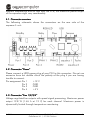
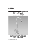
AQUAERO 5
User and installation manual
aquaero 5
The information contained in this manual is subject to change without prior
notice. All rights reserved.
Current as of April 2011
ENGLISH: PAGE 1
DEUTSCH: SEITE 13
© 2011
Aqua Computer GmbH & Co. KG
Gelliehäuser Str. 1, 37130 Gleichen
-1-
AQUAERO 5
Table of contents
1. Scope of delivery..................................................................................3
2. Preface................................................................................................3
3. Safety precautions................................................................................3
4. Electrical connectors.............................................................................4
4.1. Connector overview...............................................................................5
4.2. Connector “Power”...............................................................................5
4.3. Connector “Fan 1/2/3/4”......................................................................5
4.4. Connector “PWM 1/2”..........................................................................6
4.5. Connector „IR-LED“...............................................................................6
4.6. Connector “aquabus 1/2”.....................................................................6
4.7. Connector „Tacho“...............................................................................7
4.8. Connector „Sensors“.............................................................................7
4.9. Connector „USB“..................................................................................7
4.10. Connector „Flow“...............................................................................8
4.11. Connector „RGB-LED“.........................................................................8
4.12. Connector „Relay“..............................................................................8
4.13. Connector „Standby“...........................................................................8
4.14. Matching optional accessories for the aquaero 5....................................9
5. Operation concept: Sensor, controller, output........................................9
5.1. Sensors..............................................................................................10
5.2. Controllers.........................................................................................10
5.3. Outputs.............................................................................................10
6. Menu “User interface”........................................................................11
6.1. Language selection.............................................................................11
7. Menu “System”..................................................................................11
8. Menu “Data log”................................................................................11
9. Menu “Alarm”....................................................................................11
10. Menu “Timer”..................................................................................12
11. Menu “Infrared”...............................................................................12
© 2011
Aqua Computer GmbH & Co. KG
Gelliehäuser Str. 1, 37130 Gleichen
-2-
AQUAERO 5
1. Scope of delivery
1x aquaero 5 (ready to install)
4x Temperature sensor 70 cm
1x Internal USB connection cable (5pin), length ca. 100 cm
1x aquabus / speed signal cable
Mounting material
1x This manual
aquaero 5 XT only:
1x aquaremote infrared remote control
2. Preface
Dear valued customer,
customer
we congratulate you on the purchase of an aquaero 5 made by Aqua
Computer GmbH & Co. KG. We are one of the most renowned
manufacturers of PC water cooling systems in Germany. Our production
meets highest quality standards.
Should you have questions or suggestions regarding our products, you are
invited to visit the forums on our website www.aqua-computer.de or contact
our customer support.
Considering the fast technical development, we reserve the right to be able to
perform alterations to the products at any time. It therefore is possible that
your product does not correspond precisely to the descriptions or especially
the illustrations in this manual.
We hope you will enjoy your new aquaero 5.
Your Aqua Computer team
3. Safety precautions
The following safety precautions have to be observed at all times:
1. Read this manual thoroughly and entirely!
© 2011
Aqua Computer GmbH & Co. KG
Gelliehäuser Str. 1, 37130 Gleichen
-3-
AQUAERO 5
2. Save your data onto suitable media before working on your hardware!
3. The aquaero may only be used completely assembled in a computer
case!
4. Never touch, connect or separate cables or electronic components
while in use! The electronic components and the heat sink (if installed)
may get very hot during operation! Wait for at least 30 minutes after
powering down the device before touching any components!
5. Do not turn on your computer unless you are absolutely certain that all
cables are securely and correctly connected to the aquaero!
6. The relay-output may be powered at a maximum of 12 V! The current
must not exceed 1 Ampere!
7. This product is not designed for use in life support appliances, devices,
or systems where malfunction of this product can reasonably be expected
to result in personal injury. Aqua Computer GmbH & Co. KG customers
using or selling this product for use in such application do so at their own risk
and agree to fully indemnify Aqua Computer GmbH & Co. KG for any
damages resulting from such application.
4. Electrical connectors
ATTENTION: Completely turn off your power supply unit or disconnect the
mains power cord from the wall outlet before connecting or disconnecting
any cables to/from the device! The PCB and components may get very hot
during operation! Wait for at least 30 minutes after powering down the
device before touching the PCB, heat sink or any components of the device!
The aquaero 5 controller is equipped with several internal temperature
sensors to monitor critical electronic components. Should temperature values
exceed predefined safety limits, related outputs will be set to 100 % power as
a first step to minimize power dissipation. Should the temperature continue to
rise, the outputs will be switched off completely. Consecutively, depending on
© 2011
Aqua Computer GmbH & Co. KG
Gelliehäuser Str. 1, 37130 Gleichen
-4-
AQUAERO 5
ambient temperature and air flow over the PCB, the maximum power output
of the aquaero might vary considerably.
4.1. Connector overview
The following schematic shows the connectors on the rear side of the
aquaero 5 unit:
4.2. Connector “Power”
Please connect a HDD power plug of your PSU to this connector. Do not use
excessive force but double check the polarity of the plug if you are having
trouble to connect.
Pin assignment: Pin 1
+12 V
Pin 2
GND
Pin 3
GND
Pin 4
+5 V
4.3. Connector “Fan 1/2/3/4”
Voltage regulated fan outputs with speed signal processing. Maximum power
output 19.8 W (1.65 A at 12 V) for each channel. Maximum power is
dynamically limited through temperature monitoring.
© 2011
Aqua Computer GmbH & Co. KG
Gelliehäuser Str. 1, 37130 Gleichen
-5-
AQUAERO 5
Special feature “Fan 1”: This connector can alternatively be connected to a
flow sensor. If connected to a flow sensor, select “Sensors” → “Flow sensors”
→ “Flow 2” from the menu and set “Mode” to “Fan 1 = Flow sensor”.
Special feature “Fan 4”: This connector can be used for conventional fans or
PWM controlled fans. For PWM fans, select “Outputs” → “Fans” → “Fan 4”
from the menu and set “Control mode” to “PWM-regulated”.
Pin assignment: Pin 1: GND
Pin 2: 0-12 V
Pin 3: Speed signal
Pin 4: PWM signal (Fan 4 only)
4.4. Connector “PWM 1/2”
Pulse width modulated 12 V outputs, maximum current load 1 A, carrier
frequency 15 kHz.
Pin assignment: Pin 1: VCC
Pin 2: GND
4.5. Connector „IR-LED“
Connector for an infrared transmitter LED. This output is not yet functional
with firmware version 1010 and will be activated with an forthcoming
firmware update.
Pin assignment: Pin 1: GND
Pin 2: +12 V
Pin 3: Signal
Pin 4: +5 V
4.6. Connector “aquabus 1/2”
Connectors for communication with other devices from Aqua Computer. The
aquaero 5 features one „low speed“ (aquabus 1) and one „high speed“
(aquabus 2) port.
Products compatible to the “low speed” port:
–
multiswitch USB
–
tubemeter USB
Products compatible to the “high speed” port:
–
aquastream XT
–
poweradjust 2 USB (Firmware 1003 or higher)
© 2011
Aqua Computer GmbH & Co. KG
Gelliehäuser Str. 1, 37130 Gleichen
-6-
AQUAERO 5
Pin assignment: Pin 1: GND
Pin 2: SDA
Pin 3: SCL
Pin 4: +5 V
4.7. Connector „Tacho“
Depending on configuration, the aquaero 5 can generate a speed signal
which is available for processing through this connector. This speed signal
can for example be configured to cease function upon alarm events and
thereby relay the alarm status to a fan connector of your motherboard.
Functionality of the speed signal can be configured using the menu entries
“Alarm” and “Timer”. For details on how to configure your motherboard to
process the speed signal, please refer to the manual of your motherboard.
4.8. Connector „Sensors“
Connector for up to 8 temperature sensors. For compatible sensors, please
refer to chapter 4.14.
Pin assignment: Pin 1/2: Sensor 1
Pin 3/4: Sensor 2
Pin 5/6: Sensor 3
Pin 7/8: Sensor 4
Pin 9/10: Sensor 5
Pin 11/12: Sensor 6
Pin 13/14: Sensor 7
Pin 15/16: Sensor 8
4.9. Connector „USB“
This connector is used for USB communication to the PC and for standby
power supply. Take special care to make sure the pin alignment matches
your motherboard!
Pin assignment: Pin 1
+5 V
Pin 2
DPin 3
D+
Pin 4
GND
Pin 5
GND
© 2011
Aqua Computer GmbH & Co. KG
Gelliehäuser Str. 1, 37130 Gleichen
-7-
AQUAERO 5
4.10. Connector „Flow“
Connector for a flow sensor. Use sensors and cables specified by Aqua
Computer only!
Pin assignment: Pin 1: GND
Pin 2: 5 V
Pin 3: Speed signal
4.11. Connector „RGB-LED“
Connector for up to three LEDs or one two-color or RGB illumination module
(not included in delivery). High brightness LEDs (Imax 20 mA, U 3-4V) may
be connected without series resistor, a series resistor is built into the aquaero
5.
Pin assignment: Pin 1: VCC LED 1
Pin 2: VCC LED 2
Pin 3: GND
Pin 4: VCC LED 3
4.12. Connector „Relay“
Floating contact (changeover contact). May be used for emergency shutdown
of the PC which requires additional accessories (not included in delivery) or
for free use. Maximum contact rating 1 A, 12 V.
Pin assignment: Pin 1: normally open
Pin 2: normally connected
Pin 3: common connector
4.13. Connector „Standby“
Connector for additional power supply from the 5 Volts standby power line of
the power supply unit. If connected to standby power, the aquaero 5 will
remain functional while the computer is in soft off state even if no USB
standby power is supplied. Use cables specified by Aqua Computer only (not
included in delivery)!
Pin assignment: Pin 1: GND
Pin 2: +5 V Standby
© 2011
Aqua Computer GmbH & Co. KG
Gelliehäuser Str. 1, 37130 Gleichen
-8-
AQUAERO 5
4.14. Matching optional accessories for the aquaero 5
–
–
–
–
–
–
–
–
–
–
–
–
–
–
–
–
–
–
–
–
aquaremote infrared remote control (article no. 53088)
poweradjust 2 USB (article 53082/53083)
aquastream XT (article no. 41059/41060/41061)
tubemeter USB (article no. 93265)
multiswitch USB (article no. 53050/53051)
Water cooler for aquaero 5, G1/4 (article no. 53093)
Passive heat sink for aquaero 5 (article no. 53094)
Flow sensor (article no. 53061)
Flow sensor „high flow“ (article no. 53068)
Flow sensor cable (article no. 53027)
aquaero power connect - 24 pin ATX standby power / ATX break
(article no. 53047)
Temperature sensor (article no. 53026)
plug&cool temperature sensor (article no. 53025)
Temperature sensor inline G1/4 (article no. 53066)
Temperature sensor internal/external thread G1/4 (article no. 53067)
RGB illumination module (article no. 34930)
Multi color illumination module blue/red (article no. 34916)
Plug for relay connector, 3 contacts (article no. 53080)
Plug for PWM connector, 2 contacts (article no. 53036)
aquabus / speed signal cable (article no. 93111)
5. Operation concept: Sensor, controller, output
The aquaero 5 uses an extremely flexible concept for linking sensors to the
various outputs.
The device automatically determines which sensors
ensors are currently connected
and will display only these sensors in the configuration menus. For example,
after connecting a poweradjust 2 unit to the aquaero 5 via aquabus
connection, the corresponding sensors will appear in the configuration
menus of the aquaero and can be used for automatic control.
Linking element between (temperature) sensors and the outputs are the
various controllers,
controllers which offer comprehensive configuration options. After
selecting the appropriate controller model for the particular application, the
controller can be configured. The controller will calculate and update an
output value, which can then be assigned to an output.
© 2011
Aqua Computer GmbH & Co. KG
Gelliehäuser Str. 1, 37130 Gleichen
-9-
AQUAERO 5
After assigning a controller to an output and configuring output specific
parameters like minimum power or start boost, the signal chain from sensor
via controller to output is completely configured.
5.1. Sensors
The following sensors are available:
–
Temperature sensors
– Virtual sensors: Can be used to determine maximum, average or
minimum value of up to three temperature sensors.
–
Software sensors: These values can be written into the device using the
aquasuite software. They can for example be used to transmit the
current CPU temperature to the aquaero 5 and use this value for
controlling fan speeds.
–
Flow sensors
–
Power measurement: Allow calculating power dissipation from a
temperature difference and corresponding flow rate.
5.2. Controllers
The following controller models are available:
–
Curve controllers: Adjustable control curves, defined by 16 temperature
values and corresponding output values.
–
Target value controllers: Automatic output adjustment to match a
predefined target temperature.
–
Two point controllers: Simple on/off controller, using a lower and upper
temperature limit.
–
Preset values: Constant preset values.
–
RGB LED controller: Temperature-dependent color gradient controller
for the RGB LED output.
5.3. Outputs
The following outputs are available:
–
Fans
–
Power outputs
–
LED outputs
© 2011
Aqua Computer GmbH & Co. KG
Gelliehäuser Str. 1, 37130 Gleichen
- 10 -
AQUAERO 5
6. Menu “User interface”
The menu entry “User interface” is used for language and unit selection as
well as configuring display and buttons. In particular, each of the up to 32
available pages displayed in normal operation can be individually
configured, some of which have factory presets that can easily be adjusted.
6.1. Language selection
In order to change the language for display pages and menus of the
aquaero 5, simply press the enter button of the aquaero 5 (or the OK button
of the aqquaremote if available) four times while the device is normal display
operation. Select the desired language and confirm your selection by
pressing the enter button again.
7. Menu “System”
The menu entry “System” contains time and date configuration, standby
options and user profile management. The profile management can be used
to save up to four individual configuration sets, which then can be activated
as desired. Additionally, factory defaults can be restored using the profile
management.
8. Menu “Data log”
The aquaero 5 unit can be configured to record measured values over an
extended period of time. The menu “Log data” can be used to configure up
to 16 measured values to be recorded at adjustable time intervals. The
recorded information can then be displayed as charts on the aquaero display
itself (menu “User interface” → “Information pages”) or be transmitted to the
Windows software aquasuite via USB connection.
9. Menu “Alarm”
The aquaero 5 features eight alarm levels, which van be configured
individually. Up to three actions can be configured for each alarm level. For
alarm actions, speed signal output, alarm buzzer, relay, profile selection and
USB keyboard commands are available.
© 2011
Aqua Computer GmbH & Co. KG
Gelliehäuser Str. 1, 37130 Gleichen
- 11 -
AQUAERO 5
After configuring alarm levels, alarm limits can be configured for various
sensors and corresponding alarm levels can be set.
Higher alarm levels are always processed with higher priority than lower
alarm levels. Depending on the severity of the malfunction, graduated alarm
actions can be configured. For example, the aquaero could be configured to
activate the integrated alarm buzzer when a temperature sensor reads more
than 40 °C, and to shut down the PC if the same sensor reads more than 50
°C using the relay output (optional accessories required).
10. Menu “Timer”
The aquaero 5 features a clock timer to perform various actions on
predefined times and days of the week. For timer actions, speed signal
output, alarm buzzer, relay, profile selection and USB keyboard commands
are available.
11. Menu “Infrared”
The menu entry “Infrared” is used to configure the infrared receiver of the
aquaero 5. The three tiers of the aquaremote remote control (aquaero, PC
mouse, PC keyboard) can be individually activated or deactivated. For
default configuration, powering the PC up or down by remote control is
deactivated for safety reasons. The aquaremote has a red power button that
can be used for this function, the aquaero 5 can be trained to accept the
corresponding infrared command using the menu entry “Switch PC on/off via
infrared”.
© 2011
Aqua Computer GmbH & Co. KG
Gelliehäuser Str. 1, 37130 Gleichen
- 12 -