1
User Manual
Scales of TMX series
Manual number:
ITKU-36-06-09-11-A
Terminal E2R Ewidencja v. 1.1.6.119
MANUFACTURER OF ELECTRONIC
WEIGHING INSTRUMENTS
RADWAG 26 – 600 Radom 28 Bracka Street - POLAND
Phone +48 48 38 48 800, phone/fax. +48 48 385 00 10
Selling department +48 48 366 80 06
www.radwag.com
SEPTEMBER 2011
-2-
TABLE OF CONTENTS
1.
2.
3.
4.
5.
6.
7.
8.
9.
INTENDED USE ....................................................................................................................6
PRECAUTIONS .....................................................................................................................6
WARRANTY CONDITIONS...................................................................................................6
MAIN DIMENSIONS ..............................................................................................................7
DESCRIPTON OF CONNECTORS .......................................................................................8
UNPACKING AND ASSEMBLY ............................................................................................9
GETTING STARTED .............................................................................................................9
LOGGING ON......................................................................................................................10
SCALE WINDOW DISPLAY................................................................................................11
9.1. View ..............................................................................................................................11
9.2. Buttons’ functions .........................................................................................................12
10. WEIGHING PROCEDURE.................................................................................................12
10.1. Tarring ........................................................................................................................13
10.2. Hand operated tare value entering .............................................................................14
10.3. Zeroing of scale ..........................................................................................................14
10.4. Weighing on two range scales....................................................................................15
11. WINDOW NAVIGATION ....................................................................................................15
12. PRODUCT CHOICE ..........................................................................................................17
12.1. Choosing a product by name......................................................................................17
12.2. Choosing a product by code.......................................................................................19
13. CHOICE OF A CONTRACTOR .........................................................................................19
13.1. Contractor choosing by name.....................................................................................20
13.2. Contractor choosing by code......................................................................................21
14. CHOOSING A PACKING...................................................................................................22
14.1. Choosing a packing by name .....................................................................................22
14.2. Choosing a packing by code ......................................................................................23
15. STORE CHOOSING ..........................................................................................................24
16. LOT CHOOSING................................................................................................................26
17. LOT 2 CHOOSING.............................................................................................................27
18. QUANTITY NUMBER CHOOSING....................................................................................27
19. DATABASES .....................................................................................................................28
19.1. Access to databases edition.......................................................................................28
19.2. Operators’ database ...................................................................................................28
19.2.1. Adding an operator ............................................................................................29
19.2.2. Editing an operator ............................................................................................31
19.2.3. Eliminating an operator......................................................................................32
19.2.4. Operator’s authority ...........................................................................................33
19.3. Base of products.........................................................................................................34
19.3.1. Adding products.................................................................................................34
19.3.2. Product’s editing ................................................................................................37
19.3.3. Product eliminating ............................................................................................38
19.4. Contractors’ base .......................................................................................................38
19.4.1. Adding a contractor ...........................................................................................38
19.4.2. Contractor’s edition............................................................................................40
19.4.3. Contractor’s elimination .....................................................................................41
19.5. Base of packages .......................................................................................................41
19.5.1. Adding a packing ...............................................................................................41
19.5.2. Packing’s edition................................................................................................42
19.5.3. Eliminating a packing.........................................................................................43
20. COUNTING PIECES..........................................................................................................43
20.1. Enabling working mode ..............................................................................................43
20.2. Setting reference unit mass........................................................................................45
-3-
21. TRANSACTIONS ...............................................................................................................46
21.1. Starting working mode................................................................................................46
21.2. Starting a transaction..................................................................................................47
21.3. Continuing a transaction.............................................................................................49
22. STATISTICS ......................................................................................................................50
23. WEIGHING RECORDING..................................................................................................51
24. PROGRAMMABLE BUTTONS..........................................................................................52
25. LOGGING OFF ..................................................................................................................53
25.1. Logging off..................................................................................................................53
25.2. Change-logging ..........................................................................................................53
25.3. Switching off a terminal ..............................................................................................54
26. CHECKWEIGHING THRESHOLDS ..................................................................................55
27. PROGRAM’S OPTIONS ....................................................................................................55
27.1. Weighing parameters .................................................................................................55
27.2. Operators....................................................................................................................56
27.2.1. Operator’s edition ..............................................................................................57
27.2.2. Log on procedure ..............................................................................................57
27.2.3. Authorization......................................................................................................59
27.3. Devices.......................................................................................................................60
27.3.1. Scales ................................................................................................................61
27.3.2. Printer ................................................................................................................63
27.3.3. CGM – Apparatus for testing conformation .......................................................66
27.3.4. Output mode......................................................................................................67
27.4. Reports .......................................................................................................................69
27.4.1. Date ...................................................................................................................70
27.4.2. Laps ...................................................................................................................71
27.4.3. Print monitoring .................................................................................................75
27.4.4. Export to a file....................................................................................................77
27.4.5. Programme closing............................................................................................77
27.5. Others.........................................................................................................................77
27.5.1. Interface view ....................................................................................................78
27.5.2. Buttons’ functions ..............................................................................................85
27.5.3. Language ...........................................................................................................88
27.5.4. Application closing.............................................................................................89
27.6. Alibi.............................................................................................................................90
27.6.1. Enabling write memory Alibi ..............................................................................92
27.6.2. Deleting a measurement of memory Alibi..........................................................92
27.6.3. Export measurements alibi to a csv file .............................................................93
27.6.4. Filter...................................................................................................................93
27.7. IN/OUT configuration..................................................................................................94
27.7.1. Inputs configuration ...........................................................................................94
27.7.2. Outputs configuration ........................................................................................95
27.7.3. Other options .....................................................................................................96
28. CONFIGURATOR PROGRAM ..........................................................................................97
28.1. Basic Configuration ....................................................................................................97
28.2. External configuration.................................................................................................99
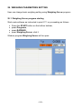
29. WEIGHING PARAMETRES SETTING ............................................................................102
29.1. Weighing Server program starting............................................................................102
29.2. List of software menu ...............................................................................................103
29.3. Parameters of scale software ...................................................................................103
29.3.1. Readout of parameters ....................................................................................103
29.3.2. Save changes procedure.................................................................................103
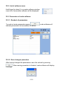
29.4. Setting a filtering level ..............................................................................................104
29.5. Median filter ..............................................................................................................104
29.6. Autozero function......................................................................................................105
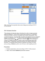
29.7. Scale software settings.............................................................................................106
-4-
29.8. Closing WeighingServer program.............................................................................107
30. ERROR MESSAGES .......................................................................................................107
31. LABEL DESIGNING ........................................................................................................107
31.1. Label pattern making ................................................................................................108
31.2. Inventory of variables: ..............................................................................................111
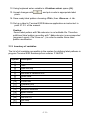
32. DIAGRAMS OF CONNECTION CABLES .......................................................................113
32.1. USB cable (adapter) .................................................................................................113
32.2. USB printer cable .....................................................................................................113
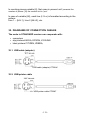
32.3. RS232 printer cable..................................................................................................114
32.4. Ethernet cable ..........................................................................................................114
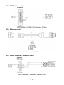
32.5. RS232 terminal – computer cable ............................................................................114
32.6. RS232, RS485 cable – colours ................................................................................115
32.7. RS232C cable – colours...........................................................................................115
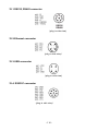
33. CONNECTORS................................................................................................................115
33.1. RS232, RS485 connector.........................................................................................116
33.2. Ethernet connector ...................................................................................................116
33.3. USB connector .........................................................................................................116
33.4. RS232C connector ...................................................................................................116
34. SPECIFICATION OF ADDITIONAL MODULES..............................................................117
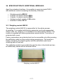
34.1. Weighing module MW-02 .........................................................................................117
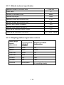
34.1.1. Module technical specification .........................................................................118
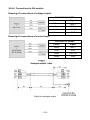
34.1.2. Weighing platform signal wires colours ...........................................................118
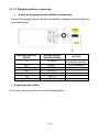
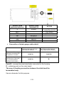
34.1.3. Weighing platform connecting .........................................................................119
34.1.4. The way of installing inside PUE 5 ..................................................................121
34.2. Additional 8 inputs / 8 outputs module .....................................................................122
34.2.1. Technical specification ....................................................................................123
34.2.2. Installing method in PUE 5 terminal ................................................................123
34.2.3. I/O diagram ......................................................................................................124
34.2.4. Description of input output wires PT0082:.......................................................124
34.3. WE 4 - 4 inputs / 4 outputs module ..........................................................................125
34.3.1. Technical specification ....................................................................................125
34.3.2. Colours of cables for I/O PT0083: ...................................................................126
34.3.3. Installing method in PUE 5 terminal ................................................................126
34.4. Analogue output module AN series ..........................................................................127
34.4.1. Technical specification ....................................................................................127
34.4.2. The way of installing inside PUE 5 ..................................................................127
34.4.3. Configuration of work modes of analogue modules ........................................128
34.4.4. Connections to AN module..............................................................................129
34.5. Profibus interface DP V1 ..........................................................................................130
34.5.1. Technical specification ....................................................................................130
34.5.2. Colours of wires...............................................................................................130
34.5.3. The way of installing inside PUE 5 ..................................................................130
35. ADDITIONAL EQUIPMENT .............................................................................................132
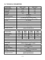
36. TECHNICAL PARAMETERS...........................................................................................133
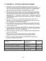
37. APPENDIX A – SETTING A BARCODE SCANNER.......................................................134
-5-
1. INTENDED USE
Scales of TMS series with TERMINAL E2R EWIDENCJA are intended to
be used for measuring and at the same time recording the data in local
database or on server. The application is especially important when the
weighed products are not directly related one to another by any common
data or they are not a part of the weighing process with its beginning and
end, for example deal or order. The net of scales connected together
enables transmitting the measurement results to the main database
installed on server.
2. PRECAUTIONS
A. Please, read carefully this user manual and use the device according
to its intended use;
B. Weighed loads should be placed in most possible central part of
scale pan;
C. Do not clean the device with agents causing corrosion;
D. Gross mass of goods loaded on weighing pan should be lower than
maximal capacity of the scale;
E. Do not leave heavy loads on the pan for long time;
F. In case of failure, scale power supply should be disconnected
immediately;
G. Devices that are to be withdrawn from usage should be utilized
according to the law regulations.
3. WARRANTY CONDITIONS
A. RADWAG is obliged to repair or exchange those elements that appear
to be faulty because of production and construction reasons,
B. Defining defects of unclear origin and outlining methods of their
elimination can be settled only in presence of a user and the
manufacturer representatives,
C. RADWAG does not take any responsibility in case of damages or
losses caused by non-authorized or inappropriate production or
service procedures,
-6-
D. Warranty does not cover:
• Mechanical failures caused by inappropriate maintenance
of the device or failures of thermal of chemical origin or
caused by atmospheric discharge, overvoltage in
mains or other random events,
• Cleaning service.
E. Warranty expires after:
• Access by an unauthorized service,
• Intrusion into mechanical or electronic construction
of unauthorized people,
• Removing or destroying protection stickers.
F. The detailed warranty conditions are specified in warranty certificate.
G. Authorized service line:+48 48 384 88 00
ext. 106 or 107.
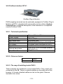
4. MAIN DIMENSIONS
Main dimensions of PUE 5
-7-
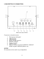
5. DESCRIPTON OF CONNECTORS
Back side view of PUE 5
Connectors in standard version:
1
2
3
4
5
6
7
8
Strain gauge cable gland
USB connector
USB connector
RS232, RS485 connector
Ethernet connector
Power cord cable
ON/OFF switch
Glands of optional equipment (8IN/8OUT, 4IN/4OUT,
RS485 via gland, additional platform, etc)
NOTICE:
All connectors can be used in any configurations.
-8-
6. UNPACKING AND ASSEMBLY
A. Remove the scale from the packaging,
B. Place the scale on even and hard surface far from heat sources,
C. Scale should be levelled by turning levelling foot. Levelling is
correct if air bubble is in central position of level indicator located
on scale’s base.
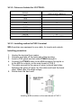
7. GETTING STARTED
• Turn on the scale pressing the ON/OFF switch on the back side
of the terminal. Then Windows loading will start.
• After the starting procedure, the main window of TERMINAL E2
EWIDENCJA application will be displayed automatically.
Notice:
The main programme’s window view can be changed by choosing suitable
setting options.
-9-
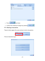
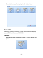
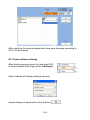
8. LOGGING ON
You have to log on every time you start the scale.
Caution:
Logging on is necessary in order to record weighing results and to choose
article, contractor, wrappings, store, lot number from the database
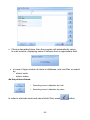
Procedure:
• While in the main application window, press ”log in”, then this will
appear:
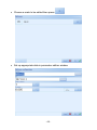
• Press „Operator 1” , then the main window will appear and the
information about the logged user will be shown in top-left corner
of the application:
- 10 -
Caution:
„Operator 1” has got the „administrator’s” authority, what makes a scale’s
user have direct access to all the program functions. The application
consists of four authority levels, which are described later in the manual.
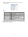
In the information line the following can be found:
Log off time
-
Time of user’s logging off or turning on
terminal’s applications
User’s name
Time of logging
-
User’s name and the time of logging
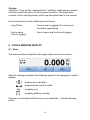
9. SCALE WINDOW DISPLAY
9.1. View
The scale window is located in the upper right corner of the screen:
After the starting procedure the following symbols be displayed in scale’s
window:
- precise zero indication
- measurement result is stable
kg
- weighing unit
- weighing platform number
If the pan is unloaded and there is no zero indication – click the zeroing
button.
- 11 -
9.2. Buttons’ functions
Zeroing of scale
Tarring
Hand-operated tare entering
10. WEIGHING PROCEDURE
appears the result can be read.
Put a load on the scale pan. When
In order to record the weighing result press:
Caution:
To save the weighing result operator must be logged on and product must
be chosen from database first.
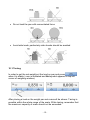
In order to assure long-term operation and correct measurement results,
follow the steps:
• Loads should be placed on the pan slowly and carefully in order
to avoid mechanical shocks:
• Loads should be placed centrally on the pan (errors caused
by eccentric weighing are outlined by standard PN-EN 45501
point 3.5 and 3.6.2):
- 12 -
• Do not load the pan with concentrated force:
• Avoid side loads, particularly side shocks should be avoided
10.1. Tarring
In order to get the net weight put the load on pan and press
when it is stable ( zero is indicated and Net symbol appears in top left
corner of weighing window).
After placing a load on the weight pan net mass will be shown. Tarring is
possible within the whole range of the scale. While tarring, remember that
the maximum capacity of scale should not be exceeded.
- 13 -
After unloading product and packing from the pan the display shows the
tarred value with “minus” sign:
Notice:
Tarring process cannot be performed while the display shows a negative
or zero value. Then Err3 will appear on weighing window display.
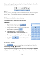
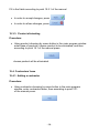
10.2. Hand operated tare value entering
It is also possible to enter a tare value by hand.
Procedure:
• While in main window press
,
and you will see the following window:
• Using number buttons enter the required value
and accept it by clicking
,
•
The scale returns to weighing mode.
The inscribed value will be preceded by „–”,
•
Tarring can be applied at any time during weighing.
•
Use button
value.
to remove the previous
10.3. Zeroing of scale
Press
Symbols:
in program’s weighing window to get zero indication.
and
will appear.
Zeroing is equivalent to setting a new zero point interpreted by the scale
as the precise zero point. Zeroing can be performed only when display
is stable.
- 14 -
Notice:
Zeroing is possible only within the range of ±2% of maximum scale’s
capacity. If the zero value is beyond this range, Err2 message will be
displayed.
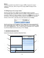
10.4. Weighing on two range scales
Switching between the I range and the II range weighing appears
automatically without operator’s presence when I range maximum value is
symbol in the top
exceeded. Starting II range weighing is indicated by
left corner of the scale window. When loading is eliminated the indication
returns to zero value. Until then the scale remains in the II range.
Switching between the II range and the I range takes place automatically
after loading elimination, when the indication returns to AUTOZERO range
appears. Then II range symbol disappears and weighing
and symbol
is performed again with the accuracy of the I range.
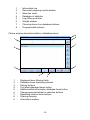
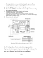
11. WINDOW NAVIGATION
MAIN PROGRAM’S WINDOW DESCRIPTION
1
6
2
7
3
4
8
5
- 15 -
1
2
3
4
5
6
7
8
-
Information line
Recorded weighing results window
Mass bar chart
Database of statistics
Log off/log on button
Weight window
Choosing items from database buttons
Programmable buttons
Choice window description/edition of database items
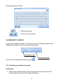
9
8
1
7
2
6
3
4
1
2
3
4
5
6
7
8
9
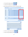
-
5
Displayed items filtering fields
Database items displaying window
Sorting buttons
Ten latest displayed items button
Addition/edition/elimination database items button
Change approval/refusal or selection buttons
Rewinding chosen items buttons
Filtering cleaning
Information window
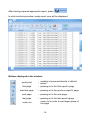
- 16 -
Screen keyboard window
-
Window clearing
-
Cursor moving arrows
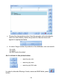
12. PRODUCT CHOICE
In the main program window the scale’s user can choose product from
database by name or code, as the picture shows:
Choosing by code
Choosing by name
To remove the selected product press
.
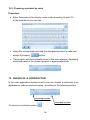
12.1. Choosing a product by name
Procedure:
• Start product choosing by name procedure according to point 12
of the manual and you will see the following:
- 17 -
• Choose the demanded product, then the program will automatically
return to main window, where the product’s code and name will
appear in appropriate fields:
• In case of large number of products in the database, user can search:
- by code
- by name
- by EAN code of product
As it is shown in the picture below:
- searching by code
- searching by name
- searching by EAN code
In order to eliminate filtering of code, name and EAN fields, press
button.
- 18 -
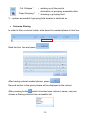
12.2. Choosing a product by code
Procedure:
• Enter the product choosing by code mode according to point 12
of the manual so you can see :
• Using the screen keyboard load the demanded product’s code and
accept it pressing
button.
• The program will automatically return to the main window, displaying
code and name of the chosen product in appropriate fields.
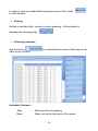
13. CHOICE OF A CONTRACTOR
In the main application window scale’s user can choose a contractor from
database by code or product’s name, according to the following picture:
Choosing by code
Choosing by name
To remove a contractor press
.
- 19 -
CAUTION!
Contractor’s choice window will be accessible after setting up its profile
in the main application window, according to point 27.5.1 of the manual.
13.1. Contractor choosing by name
Procedure:
• Choose constructor choosing by name mode according to point 13
of the manual, then you will see the following:
•
Press the required contractor’s profile and the program will
automatically return to the main window, displaying code and name
of chosen contractor in appropriate fields:
• In case of large number of contractors in database, user can filter
or search by:
− contractor’s code,
− contractor’s name
- 20 -
As it is shown in the picture below:
- Searching for contractor by code
- Searching for contractor by name
In order to eliminate code and name fields’ filtering, press
button.
13.2. Contractor choosing by code
Procedure:
• Enter constructor choosing by code mode according to point 13
of the manual, so you can see the following:
• Using screen keyboard, load the required contractor’s code, then
accept it pressing
button.
• Program will automatically return to the main window, displaying
the demanded contractor’s code and name in appropriate fields.
- 21 -
14. CHOOSING A PACKING
In the main application window the user can choose a packing by its code
or name as follows:
Choosing by code
Choosing by name
To remove a package press
.
Caution!
Packing choosing window will be accessible after setting up its profile
in the main application window, according to point 27.5.1 of the manual.
14.1. Choosing a packing by name
Procedure:
• Enter choosing a packing by name mode according to point 14 of the
manual, so you can see the following:
- 22 -
•
Press required packing, then the program will return to the main
window displaying code and name of the chosen packing
• In case of large number of packages in database user can filter or
choose by:
- code of packing,
- name of packing,
As the picture shows:
- Searching packages database by code
- Searching packages database by name
In order to eliminate code and name fields’ filter, press
button.
14.2. Choosing a packing by code
Procedure:
•
Enter choosing a packing by code mode according to point 14
of the manual so you can see the following:
- 23 -
• Using screen keyboard, enter the demanded code of packing and
accept it pressing
•
button
The program will automatically return to the main window displaying
code and name of chosen packing in appropriate fields.
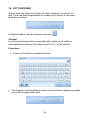
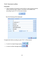
15. STORE CHOOSING
User can choose a source and target store according to following picture
- Target store choosing
- Source store choosing
To remove a store/warehouse press
.
CAUTION!
Target and source store choosing window will be accessible after setting
up its profile in the main application window according to point 27.5.1
of the manual.
Procedure:
• Choose source or target store, then you will see the following:
- 24 -
• Choose demanded store, then the program will automatically return
to main window, displaying name of chosen store in appropriate field:
• In case of large number of stores in database, user can filter or search
by:
− store’s code
− store’s name,
As the picture shows:
- Searching stores’ database by code
- Searching stores’ database by name
In order to eliminate code and name fields’ filter, press
- 25 -
button.
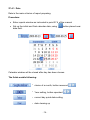
16. LOT CHOOSING
Scale’s user can load a lot number for each weighing. In order to do
that, Press the button appropriate for loading a lot number in the main
application window.
Lot/batch window can be cleared by pressing
.
Caution!
Lot choosing window will be accessible after setting up its profile in
main application window, according to point 27.5.1 of the manual.
Procedure:
• Load a lot number to keyboard window
• The program will automatically return to main window, displaying loaded
lot number in appropriate field.
- 26 -
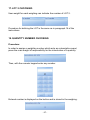
17. LOT 2 CHOOSING
User weight for each weighing can indicate the number of LOT 2.
Procedure for defining the LOT is the same as in paragraph 16 of the
instructions.
18. QUANTITY NUMBER CHOOSING
Procedure:
In order to assign a weighting number which acts as a descriptive panel,
press the main weight of responsibility for the introduction of a quantity.
Then, with the numeric keypad enter any number.
Entered number is displayed on the button and is stored in the weighing .
- 27 -
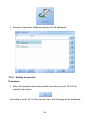
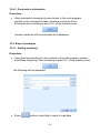
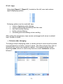
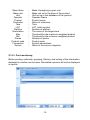
19. DATABASES
19.1. Access to databases edition
Procedure:
•
While in database choice window, press
following will be displayed:
button, then the
19.2. Operators’ database
Caution!
Operators’ database edition is accessible in the program’s options
for logged user who has the administrator’s or advanced authority.
Operators’ database can be also edited while user’s change-logging.
Procedure:
• In order to edit operators’ database, press
• Press
•
in operator’s log off window.
Press Operators button in option window
• Press Operators ’edition button
- 28 -
,
• Access to operators’ database window will be displayed:
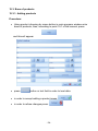
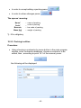
19.2.1. Adding an operator
Procedure:
• Enter the operators choosing window according to point 19.2 of the
manual, then press:
according to point 19.1 of the manual, then, the following will be displayed:
- 29 -
And as the picture shows:
name*
code*
authority
set up
password
- operator’s name field
- operator’s code field
- user’s authority type
- setting up user’s password
*) - filling in is obligatory
• Press text field or button
(code, name)
in order to load operator’s data
The buttons’ functions:
- Approval of loaded new information
- Refusal of loaded new information
- 30 -
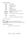
•
After operator’s code and name loading, set up authority level
pressing a button below; choose an option from unrolled list:
.
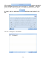
• Set up operator’s password, pressing
Using keyboard that appears on the terminal’s screen, enter the
password and accept it.
Caution!
You have to enter identical password twice, otherwise information about
error will be displayed:
• In order to accept adding an operator press:
,
• In order to refuse adding an operator press:
.
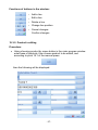
19.2.2. Editing an operator
Procedure:
• Enter operators choosing window according to point 19.2 of the
manual, choose an operator you want to edit, then, according to
point 19.1 of the manual, press:
- 31 -
this is what will appear on the screen:
Complete the fields according to information in point 19.2.1 of the manual
• In order to accept all changes, press
• In order to refuse changes, press
,
.
19.2.3. Eliminating an operator
Procedure:
• Enter operators choosing window according to point 19.2 of the
manual, then according to point 19.1 press:
then the window will appear:
Accept eliminating an operator pressing:
- 32 -
.
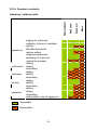
19.2.4. Operator’s authority
operations
contractors
packages
articles
operators
logging on a terminal
weighing (choice of variables)
reports
Min Max thresholds
options setting
weighing parameters
switching off a terminal
closing the program
adding
editing
eliminating
adding
editing
eliminating
adding
editing
eliminating
adding
editing
eliminating
authorization, way of logging on
- accessible
- inaccessible
- 33 -
Basic
Standard
Advanced
Administrator
Operators’ authority table
19.3. Base of products
19.3.1. Adding products
Procedure:
• Using product choosing by name button in main program window enter
base of products, then, according to point 19.1 of the manual, press:
and this will appear:
• press:
button or text field in order to load data.
• in order to accept adding a product press:
• in order to refuse changes press:
- 34 -
,
.
Fields to be completed:
Name*
Code*
EAN
Price
Mass
Tare
Min
Max
Validity time
Temperature
Edit Label
Field
VAT [%]
Label
-
name of product
code of product
EAN bar code of product
retail price of product
net weight
tare weight
product’s min threshold
product’s max threshold
No of validity days of a product after the day of
- weighing
- Storage temperature (text field)
- This field can hold any information about the product
- Interest rate of VAT
- File selection box printed labels for the goods
*) – filling in is compulsory
Notice!
Using button
a barcode can be read directly from the label.
A barcode scanner allows quick product selection provided it is described
by EAN code field.
Editing the window of ingredients
- 35 -
After pressing
a window appears in
which additional information can be inscribed e.g.: ingredients. Every line
(L1-Ln) can be printed separately, see additional information in ch. 31.2.
and then enter the text for the
In order to add this field press
line.
The line is displayed in the window.
- 36 -
Functions of buttons in the window:
- Add a line
- Edit a line
- Delete a line
- Change line position
- Cancel changes
Confirm changes
19.3.2. Product’s editing
Procedure:
• Using choosing product by name button in the main program window
enter base of products, then choose product to be edited, and
according to point 19.1 of the manual press:
then the following will be displayed:
- 37 -
Fill in the fields according to point 19.3.1 of the manual
• In order to accept changes, press
• In order to refuse changes, press
,
.
19.3.3. Product eliminating
Procedure:
• Using product choosing by name button in the main program window
enter base of products, choose product to be eliminated, and then
according to point 19.1 of the manual press:
chosen product will be eliminated.
19.4. Contractors’ base
19.4.1. Adding a contractor
Procedure:
• Using contractor choosing by name button in the main program
window, enter contractors base, then according to point 19.1
of the manual press:
- 38 -
the following will appear:
• Press
•
button or text field in order to load data.
,
In order to accept adding a contractor press:
• In order to eliminate changes press
.
Fields to be completed:
Code*
Name*
Place of living
Street
TIN
Post code
Discount [%]
Label code
-
product’s code
product’s name
contractor’s place of living
street and number
tax identification number
post code
discount assigned for contractor
code of label printed for contractor
*) - filling in is compulsory
- 39 -
19.4.2. Contractor’s edition
Procedure:
• Using contractor choosing by name button in main program window,
enter contractors base, choose a contractor to be edited, then
according to point 19.1 of the manual press:
then the following will be displayed:
Complete the fields according to point 19.4.1 of the manual.
• In order to accept changes press
,
• In order to refuse changes press
.
- 40 -
19.4.3. Contractor’s elimination
Procedure:
• Using contractor choosing by name button in the main program
window, enter contractors’ base, choose a contractor to be
eliminated and according to point 19.1 of the manual press:
chosen contractor will be eliminated from database.
19.5. Base of packages
19.5.1. Adding a packing
Procedure:
• Using packing choosing by name button in the main program window,
enter base of packing, then according to point 19.1 of the manual press:
the following will be displayed:
• Press
button or text field in order to load data
- 41 -
• In order to accept adding a packing press:
• In order to refuse changes press:
,
.
The spaces’ meaning:
Name*
Code*
Barcode
Mass [kg]
-
name of packing
code of packing
bar code of packing
weight of packing
*) - fill in obligatory
19.5.2. Packing’s edition
Procedure:
• Using choosing a contractor by name button in the main program
window, enter contractors database, choose a contractor to be
edited, then , according to point 19.1 of the manual, press:
the following will be displayed:
- 42 -
complete the fields according to point 19.5.1 of the manual.
• In order to accept changes, press:
,
• In order to refuse changes, press:
.
19.5.3. Eliminating a packing
Procedure:
• Using choosing a packing by name button in the main program
window, enter packages base, choose a packing to be eliminated
and, according to point 19.1 of the manual, press:
chosen packing will be eliminated from database.
20. COUNTING PIECES
Standard software in weighing terminals PUE5 comprises an additional
working mode – counting pieces. The database of weighings holds
measurements in pieces of the same weight. If counting pieces is
performed in an additional container it needs to be tarred before
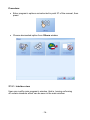
putting counting pieces into it.
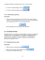
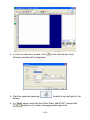
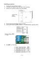
20.1. Enabling working mode
Procedure:
• While in the main window press
• While in the operator logout window press
• Then press in sequence buttons:
- 43 -
,
,
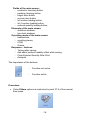
In the interface window tick Counting Pieces. You will see
.
In the interface window, select the Operating modes and Counting pieces
tab, select Active.
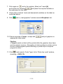
• Press
2 times.
• The introduced changes are confirmed by pressing
The working mode is on when the pcs unit is on the display:
In the weighing window additional column Pieces appears apart from
weighing
in g.
- 44 -
,
20.2. Setting reference unit mass
The reference unit mass can be set by estimating single piece mass in the
main program window using a function key attributed to this function.
Settings are described in ch. 27.5.2 of this manual.
After zeroing the platform put pieces on the pan and inscribe the quantity
in field Number of Pieces. Single piece mass is estimated automatically.
The reference unit mass can be also set in the assortment database. After
opening the window below press the button next to the mass field as shown
below.
- 45 -
The third way of setting the reference mass is to inscribe its value in the
field Mass in the window above.
21. TRANSACTIONS
PUE5 weighing terminals with the extended software version can operate in
working mode transactions. The weighing process is connected with selling
transactions – purchasing, production orders, servicing orders and stock
management. A new transactions can be created on the terminal. It can be
temporarily suspended or terminated.
Notice!
The full functionality of the transaction mode comprising stock management,
reports, supervising transactions can be obtained in the E2R Transakcje
program in PC version.
21.1. Starting working mode
Procedure:
• While in the main window press
• While in the operator logout window press
• Then press in sequence buttons:
,
,
In the window of interface outlook tick Transactions. You will see
to it.
- 46 -
next
• Press
two times.
• Confirm the introduced changes by pressing
21.2. Starting a transaction
There is button new in the main window to start a transaction.
Choose transaction type.
- 47 -
,
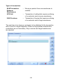
Types of transaction:
M-M Transaction
Between
Warehouses
-
Moving a product from one warehouse to
another.
SPR Sell
-
Transaction of selling that requires outlining
of a contractor and a source warehouse.
ZAK Purchase
-
Transaction of buying that requires outlining
of a contractor and a target warehouse.
The next step is to choose a contractor to be attributed to the transaction
and a source or target magazine. When moving between warehouses
contractors are not necessary. Only a source and target warehouses
are required.
- 48 -
Accessible warehouses:
Code 1
- Sell
Code 2
- Purchase
Code 3
- Warehouse1
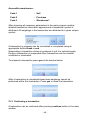
After choosing all necessary parameters in the main program window
detailed transaction information appears and a transaction symbol is
attributed. All weighings in the transaction are attributed to a given unique
symbol.
A transaction in progress can be terminated or completed using an
appropriate button break or end.
Suspending a transaction allows to postpone it until it is selected again.
During a transaction is suspended other transactions can be created,
continued or terminated.
To suspend a transaction press yes in the window below.
After a transaction is completed/closed new weighings cannot be
performed within this transaction. Press yes to close the transaction.
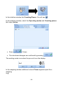
21.3. Continuing a transaction
A transaction can be continued after pressing continue button in the main
window.
- 49 -
From the list of transactions choose the one you want to continue and press
Ok.
Until the transaction is closed it is accessible on the list of suspended
transactions.
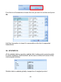
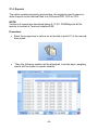
22. STATISTICS
All the statistic data is regularly updated after loading each measuring data
to scale’s database. Data interlock can be seen in bottom left corner of the
main program window.
Statistic data is updated globally irrespective of weighed product.
- 50 -
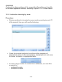
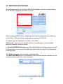
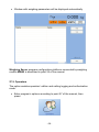
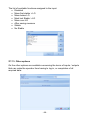
23. WEIGHING RECORDING
All weighing results are saved in MS SQL database, which is stored locally
or on another weighing terminal or server.
After pressing SAVE button, weighing result will be displayed automatically
in the chart. The last twenty weighings are present on the list.
All weighings are displayed in grams in the table.
Additionally, user can sort certain columns increasingly or decreasingly,
pressing chosen column’s name.
In Terminal E2R Ewidencja user with administrative privileges have access
to the preview, or removal of weighings made with the reports by stating the
following area.
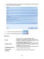
The window displays all recorded measurements.
The E2R SYSTEM which is connected to the terminal window displays a few
measurements only the current terminal.
- 51 -
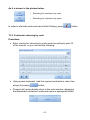
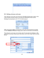
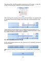
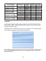
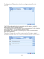
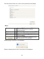
The primary filter, the filter weights is presented as of the date - to date. By
default, when you start windows are presented last two days.
After selecting the weighing and selecting edit and delete, the weighting will
be awarded as an archive which means that it will not be presented in the
report.
Jeżeli ważenie zostało odznaczone przypadkiem jako archiwalne to za
pomocą funkcji edytuj i dodaj, możemy wyłączyć status archiwalne i od tej
pory ważenie będzie prezentowane w raportach.
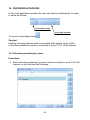
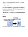
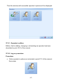
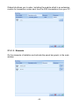
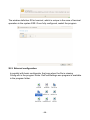
24. PROGRAMMABLE BUTTONS
In the main program window user can choose out of 5 optionally configured
function buttons.
Save button’s function can be transmitted to F1-F5 buttons or switched
off.
- 52 -
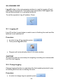
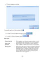
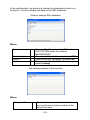
25. LOGGING OFF
Log off button in the main program window is used for logging off and
switching off the terminal. The options are accessible if the logged user
has got administrator’s or advanced authority.
To exit the operator’s log off window, Press:
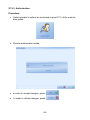
25.1. Logging off
Log off function is used when a scale’s user is finishing his work and the
terminal is not switched off.
Procedure:
• In order to log off an operator press:
• Then press Log off button:
,
• Program will automatically return to its main window
CAUTION!
All functions that are necessary for weighing recording are inaccessible
until the next logging.
25.2. Change-logging
Change-logging function is used when the first weighing terminal’s user
is finishing and next one is starting his work.
Procedure:
• In order to change-log an operator press:
- 53 -
,
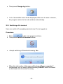
• Then press Change-log button:
•
List of accessible users will be displayed; after one of users is chosen,
the program returns to its main window automatically.
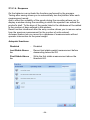
25.3. Switching off a terminal
User can switch off a weighing terminal only if he is logged on.
Procedure:
• Press
in the main program window,
• Then press Switch off terminal button:
•
Accept switching off terminal choosing Yes
• When the information „It is now safe to turn off your computer”
is displayed, turn off scale’s power pressing ON/OFF which is located
on the back side of terminal’s casing.
- 54 -
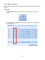
26. CHECKWEIGHING THRESHOLDS
In the main program’s window user can see checkweighing thresholds’
results (MIN,MAX) in a bar chart
Checkweighing thresholds data is taken from database of a product or
programmed with function buttons described in point 27.5.2 of the manual.
27. PROGRAM’S OPTIONS
Procedure:
• In order to enter program’s options, user with administrator’s or
advanced authority must be logged on.
• Press
in program’s main window,
• Press:
in log off operator window ,
CAUTION!
Changes made in the options must be approved in the main window by
button options
.
27.1. Weighing parameters
Setting up basic weighing parameters.
Procedure:
• Enter program’s options according to
point 27 of the manual, then press:
- 55 -
• Window with weighing parameters will be displayed automatically
Weighing Server program configuration platforms connected by weighing
module MW02 is described in point 24 of the manual.
27.2. Operators
The option enables operators’ edition and setting logging and authorization
mode.
• Enter program’s options according to point 27 of the manual, then
press:
- 56 -
Then the window with accessible operator’s options will be displayed:
27.2.1. Operator’s edition
Edition, that is adding, changing or eliminating an operator has been
described in point 19.2 of the manual.
27.2.2. Log on procedure
Procedure:
•
Enter operator’s options as instructed in point 27.2 of the manual,
then press:
- 57 -
• Choose logging procedure:
Accessible option will be marked with
.
• in order to accept loaded changes, press:
• in order to refuse changes, press:
,
.
Note that:
Select from list
-
While logging, user chooses operator’s name or code
from database and has access to list of all operators
Enter code
operator
-
While logging, user is supposed to enter operator’s
code; he does not have access to the list of operators
During start
-
Switching on the option can cause a situation that while
weighing meter is starting, logging window, with list of
accessible users or operator’s code entering window
(up to the setting) can open automatically. Entering
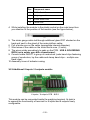
incorrect data can result in starting main program’s
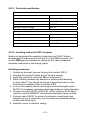
window with no user logged on
- 58 -
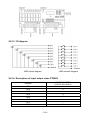
27.2.3. Authorization
Procedure:
•
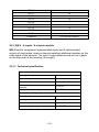
Enter operator’s options as instructed in point 27.2 of the manual,
then press:
• Choose authorization mode:
• In order to accept changes, press:
,
•
.
In order to refuse changes, press:
- 59 -
Note that:
Without
authorization
-
In order to log on to a program, the user is
supposed to enter chosen operator’s password
Password
-
While logging, password entering option is not
active
CAUTION!
If Without authorization and Select from list point 27.2.2 options are
accessible at the same time, then user with subordinated authority can log
on one of administrator’s accessible profiles, which enables him to get
access to most of program’s options.
27.3. Devices
Devices option enables devices’ and connected to weighing terminal
interfaces’ edition.
Procedure:
•
Enter program’s options as instructed in point 27 of the manual, then
press:
- 60 -
• Accessible devices will be displayed in the window below:
27.3.1. Scales
The option enables configuration of scales connected to the weighing
terminal PUE5 with Ethernet or RS232/485.
Procedure:
• Enter devices option as instructed in point 27.3 of the manual, then
press:
- 61 -
• Choose a scale to be edited then press:
.
• Set up appropriate data in parameter edition window
- 62 -
Note that:
Description
- optional characteristics of scale
Host
-
Port
- scale’s port’s number UDP/TCP
Database id
- Platform’s identification number
LO
Threshold
- LO threshold value for a particular platform.
host’s IP address, default 127.0.0.1 specifies local
computer’s address,
LO Threshold parameter is related to the function of the automatic operation
and control outputs.
For automatic operation, the measurement will not be saved to the database
until an indication of not descend below the set threshold LO net.
27.3.2. Printer
The option enables setting up labelling printer, which is installed in
operational system. Additionally, it is possible to design a label for labelling
printer and indicate saved label’s file.
CAUTION!
Now it is possible to set up a printer which prints labels after Save button in
the main program’s window has been pressed.
Procedure:
•
Enter devices options as instructed in 27.3 of the manual, then press:
- 63 -
• Then window of options accessible for designing and labelling printer
prints setting will be displayed
• In order to accept changes press:
,
• In order to refuse changes, press:
.
Note that:
Name
Design labels
Label patterns file
Active label
printing
Here you can choose labelling printer
accessible in operational system. After printer
has been installed in operational system, it will
be added to the list automatically.
Starting Edytor Etykiet program, used for label
- designing. To find out how the program works,
read point 26 of the manual.
Indicating recorded on local disc file which will
be the printed label’s pattern.
- Label printing switching on /off options
- 64 -
Labels printing active
while measurement
recording
Additional options associated with printing
labels, which allows you to disable printing of
labels during the recording. Enable option to
print labels for each record.
Printed labels
Number of printed labels,
- When set to 0, you write the part number printed
labels.
CAUTION!
Printing labels is available after setting the printer, the standard label and
select the two options Active printing.
• Select the number of labels
If the parameter number of printed labels is set to 0 then
the record appears in the following dialog choose the
number of labels. Entering any number of prints the same
number of labels.
• Select the label template
When a label indicating the file, remember that before it is placed in the
location: C:\Program Files\RADWAG\Terminal E2R Ewidencja\lab. Labels
saved in this folder should have the extension *. lb.
- 65 -
27.3.3. CGM – Apparatus for testing conformation
The program works with the apparatus to examine the conformation which
allows registration at the weighing of information on meat quality.
Hardware configuration requires you to set the communication port and
speed.
Procedure:
• Enter devices option as instructed in point 27.3 of the manual, then
press:
• You will then see a dialog where you can set the COM port to which the
terminal device is connected.
- 66 -
27.3.4. Output mode
Output mode options allows you to configure the two selected outputs are
activated depending on the current position in relation to 0, the threshold
MIN and MAX currently selected item.
This feature can be used to control the process of dispensing the goods or
alarm thresholds.
Procedure:
• Enter devices option as instructed in point 27.3 of the manual, then
press:
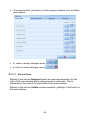
• Then in the window, select one of the modes for thresholds and assign
the starting threshold.
- 67 -
OUTPUT MODE
THRESHOLD
Threshold 1,2 to MIN
Threshold 2 to MAX
Threshold 1 to MIN
Threshold 1,2 to MAX
Threshold 1 to MIN
Threshold 2 to MAX
0
Threshold 1 from MIN
Threshold 1,2 from MAX
0
Threshold 1 from MIN
Threshold 2 from MAX
1
2
1
2
1
2
1
2
3
1
2
3
STATE OF
MASS
0 - MIN
MIN- MAX
0 - MIN
MIN- MAX
0 - MIN
MIN- MAX
0 - MIN
MIN- MAX
> MAX
0 - MIN
MIN- MAX
> MAX
Dosing
rough
1
0
1
1
1
0
0
1
1
0
1
0
Dosing
accurate
1
1
0
1
0
1
0
0
1
0
0
1
CAUTION !
In the case of mode 3 release trigger outputs to turn off the third fret on the
threshold dose MAX. Dosing process will be activated only when the mass
reaches the platform MIN.
Thresholds can be attributed only to go free. In the case of occupied disable
all the outputs assigned functions at the point 27.7.2
After making changes to output mode, the new functionality will be allocated
only to the newly selected item from the main program window. Select the
product to test out.
- 68 -
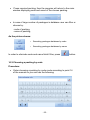
27.4. Reports
The option enables preparing and printing the weighing results report or
write a report on the terminal disk in a file format PDF, XLS or CSV.
NOTE:
Versions of reports are described below 9.11.9.0. PUE5Reports.dll file
reports is located at Terminal installed E2R.
Procedure:
• Enter the programme’s options as instructed in point 27 of the manual,
then press:
•
Then the following window will be displayed. Last two days’ weighing
results will be shown in reports window:
- 69 -
27.4.1. Date
Date is the main criterion of report preparing.
Procedure:
• Enter reports window as instructed in point 27.4 of the manual
• Set up the initial and final calendar date, using
date field.
button placed near
Calendar window will be closed after day has been chosen.
The fields enable following:
- choice of a month, button rewound
- Year setting, button operated
- current day quick date setting
- date clearing up
- 70 -
,
,
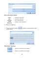
27.4.2. Laps
Using laps( Report 1, Report 2 ) located on the left, user sets various
report displaying options.
Following options can be used with laps
column displaying order change
column adding and eliminating from the view
text field column filtering
button column filtering
increasing and decreasing column sorting
After exiting the programme, laps remain unchanged until return to default
view function is used.
• Column order changing
To change column displaying order, a certain column’s name must be pulled
over and placed on another column’s name. The other column from now on
will follow the column we needed to replace. The example below shows
replacing mass column in such a way that as a result contractor column
follows it:
- 71 -
• Menu
In order to get access to extended menu, you need to hold your finger a bit
longer on a column.
Note that:
Sort ascending
-
displaying all column’s lines sorted
increasingly
displaying all column’s lines sorted
decreasingly
sorting a column’s lines elimination
grouping of displayed lines according to
chosen column; dividing results in
grouping elimination
switching on a grouping field, where
columns’ headings can be placed
Sorting descending
-
Clear sorting
-
UnGroup
-
Grouping field
-
Remove This
column
- column’s displaying elimination
Column Chooser
Best Fit
Filter editing
-
turning on adjusting window, from which
eliminated columns can be drawn
- automatic column’s size matching
-
starting an advanced options creator
filtering
Best fit (all columns) - automatic matching of all columns’ size
Full Expand *
- grouped results rewinding
- 72 -
Full Collapse *
Clear Grouping *
- winding up all the results
elimination of grouping accessible after
choosing a grouping field
*) – options accessible if grouping field window is switched on
• Columns filtering
In order to filter a column’s data, write down the needed phrase in first line:
.
Mark the first line and press:
After having entered needed phrase, press:
,
Records similar to the given phrase will be displayed in the column.
which is located near column’s name, user can
After pressing button
choose a filtering criterion from accessible list
- 73 -
In order to clear up loaded data displaying column filter, press
in main window.
• Sorting
Sorting is possible after column or menu pressing . Sorting mode is
.
displayed as changing sign:
• Choosing columns
to customization window of the drag on two
Use the button
sides of any column.
Available Columns:
Date
Mass
-
Date and time of weighing
Mass unit set on the basis of the goods
- 74 -
Mass Gram
Masa unit
Unit
Operator
Product
Contractor
Tara
LOT
Platform
Destination
Max
Min
Pieces
Product code
Transaction
Source
-
Mass of weighing in gram unit
Mass unit set in the base of the product
Unit set up in the database of the product
Operator Name
Product name
Name of contractor
Tara
LOT, batch symbol
Number of platform
The name of the target store
Threshold for the maximum weighted product
Threshold for the minimum weighted product
Number of pieces
Product code
Symbol transactions
Name of the source magazine
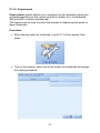
27.4.3. Print monitoring
Before printing, optionally: grouping, filtering and sorting of the information
displayed in window can be done. Eliminated columns will not be displayed
in reports.
- 75 -
After having prepared appropriate report, press:
.
In print monitoring window, ready report view will be displayed:
Buttons displayed in the window:
sending a document directly to default
printer
quick print
-
first page
- passing on to the first report’s page
previous page
- passing on to the previous report’s page
next page
- passing on to the next page
last page
- passing on to the last report’s page
zoom out
zoom out in order to see larger space of
the page
- 76 -
zoom in
print monitoring
closing
zoom in in order to see enlarged part of
the report
closing the report print monitoring
PDF File
- Export to PDF file format
Excel File
- Export to XLS file format
CSV File
- Export to CSV file format
Variable name file
export
- Variable export file name
- Constant export file name
27.4.4. Export to a file
Adequately prepared the report print to a printer installed in the operating
system. In the absence thereof, the report can be exported to a file in one
of three available file formats, ie, PDF, XLS and CSV.
All exported reports are stored on your terminal in C:\RadwagExport.
With a button Variable name file export you can export the file name to
save the report with different name which contains the date or file name
to generate a constant - data.pdf, data.csv, data.xls.
Note:
If you select the file name has all the previously saved results are deleted
and inserted in their place are new.
27.4.5. Programme closing
To exit report window, press:
.
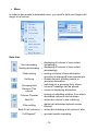
27.5. Others
The option enables interface view, functional buttons, language and various
program’s options configuration.
- 77 -
Procedure:
• Enter program’s options as instructed in point 27 of the manual, then
press:
• Choose demanded option from Others window
27.5.1. Interface view
User can modify main program’s window, that is, turning on/turning
off certain elements which can be seen in the main window.
- 78 -
Fields of the main screen:
− contractor choosing button
− packing choosing button
− target store button
− source store button
− lot number loading button,
− lot 2 number loading button,
− entered quantity loading button,
Elements of the main screen:
− statistics windows,
− bar chart windows,
Operating mode of the main screen:
− transactions,
− counting pieces,
− CGM,
− Orders.
Response - features:
− Tarring after saving,
− Ask about product usability offset while saving,
− Clear Entered Quantity After Print,
− Autoprint.
The importance of the buttons:
-
Function not acrive
-
Function active
Procedure:
•
Enter Others options as instructed in point 27.5 of the manual,
then press:
- 79 -
• Choose elements (functions) of main program window from interface
view window.
• In order to accept changes press:
,
• In order to refuse changes, press:
.
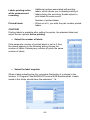
27.5.1.1. Choice fileds
Buttons in the column Required select the required parameters for the
right of the main window while writing manual or automatic. This is
equivalent to the need to fill some fields in the main window.
Buttons in the column Visible meet accessibility (visibility) of the button in
the main window.
- 80 -
27.5.1.2. Operating mode
Tab transactions module provides transaction activation button in the main
terminal and the function of enforcing the window displays the number of
record labels each time you weigh.
- 81 -
Counting pieces Tab provides activation counting module in the main
terminal.
Tab CGM provides activation of cooperation with the camera module to
study conformation in the main terminal.
CGM option to remove the data after saving measure allows for the cleaning
of the information in the main window after recording.
Optional data entry required for measuring input forces from the camera
when saving measure.
This option allow you to record the measurement with incorrect data for
testing purposes we allow you to record a measurement with misinformation.
- 82 -
Orders tab allows you to order, including the module which is an extension
module for transaction orders sent from the E2R transactions from your PC.
27.5.1.3. Elements
On the elements of statistics and activate the panel bar graph, in the main
window.
- 83 -
27.5.1.4. Response
On the behavior can activate the functions performed by the program.
Tarring after saving allows you to automatically tare the platform after each
measurement record.
Ask to offset the suitability of the goods during the recording allows you to
display a window during the recording in which the operator can extend the
product's shelf. To the days of the goods listed in the database will be added
to the number of days entered in the window.
Reset function introduced after the entry number allows you to remove value
from the previous measurement for the number of units entered.
Autosave feature lets you record to a database of measurements without
operator intervention on the panel weight.
Autoprint functions:
Disabled
-
Disabled
Last Stable Above
Lo
Record last stable weight measurement before
descending below the LO
First Stable Above
Lo
Write the first stable measurement above the
threshold LO.
- 84 -
27.5.2. Buttons’ functions
User is able to configure main program’s window programmable (functional)
buttons.
Procedure:
•
Enter Others option as instructed in point 27.5 of the manual, then
press:
• From Buttons’ Functions window choose visibility of main program’s
window buttons.
- 85 -
• After choosing button’s visibility, choose adequate function:
• In function choosing window, choose one of accessible functions:
- 86 -
• To accept the changes, press:
,
• To refuse the changes, press:
.
• After having chosen button’s function, enter button’s label.
• In order to accept changes press:
,
• In order to refuse changes, press:
.
- 87 -
Accessible functions list:
−
−
−
−
−
−
−
−
−
−
−
−
−
−
−
−
−
−
No
statistics clearing,
Record of printing a single label,
Record label without printing,
Operator’s logging off,
Operator’s logging on,
Mass pattern definig
Closing program,
Increasing the precision,
Reports,
Tare loading,
Lot number entering,
Measurement saving,
minimum threshold setting,
maximum threshold setting
creating a transaction,
terminating a transaction.
Label print
27.5.3. Language
Program is accessible in following language versions:
• Polish
• English
• German
• French
• Czech
• Spanish
Procedure:
•
Enter Others option as instructed in point
27.5 of the manual, then press:
- 88 -
• Choose required language and accept it pressing:
,
CAUTION!
Changing program’s language version does not influence Weighing Server
(weighing parameters window) or Label Editor (label designing) language
versions.
27.5.4. Application closing
Program’s closing and passing to Windows XP Embedded operational
system are accessible in other options.
Procedure:
•
Enter Others option as instructed in point 27.5 of the manual, then
press:
- 89 -
• Accept the choice in application closing window.
27.6. Alibi
E2R Terminal has the ability to save records of weighings in a place
independent of the SQL database.
Configuration options are available for the administrator and power user has
access to view content.
Weighing saved in the Alibi include:
• Time,
• Mass,
• Tare,
• Unit,
• Product name,
• Operator name,
• Contractor name,
• Serial number,
• Source stock,
• Target stock,
• Packaging.
Procedure:
•
Enter Others option as instructed in point 27.5 of the manual, then
press:
- 90 -
•
In the full terminal window will appear weighing Alibi memory.
•
Using the Actions you access to options related to memory Alibi.
- 91 -
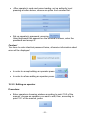
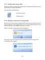
27.6.1. Enabling write memory Alibi
Enabling the Alibi is pressing the select button, Operations and Active record
measurements as described below.
The importance of the buttons:
-
Function not acrive
-
Function active
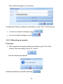
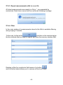
27.6.2. Deleting a measurement of memory Alibi
Button to clear the complete measurements, measurements removes the set
has secured days. The program allows you to record multiple measurements
with the number is only limited at the time of removal.
When you delete a measurement will be displayed:
Successful removal of measurements outside the specified range will be
confirmed by the message:
- 92 -
27.6.3. Export measurements alibi to a csv file
All listed measurements are saved to a file in *. csv separated by
semicolons. Each time a record will be confirmed following message.
27.6.4. Filter
In the main window of measurements stored in the Alibi is available filtering
and grouping of records.
To this end, hit the button
, and then in the window below
the box indicate that you want to search and view the memory window Alibi.
Deleting a filter for a particular field means of a button
and the button below allows you to remove a filter to all fields.
- 93 -
27.7. IN/OUT configuration
For terminal equipped PUE5 derived I / O configure their operation.
Procedure:
•
Enter Others option as instructed in point 27.5 of the manual, then
press:
27.7.1. Inputs configuration
On the input we can assign a specific function to the selected input
depending on its activation or deactivation. The assignment of the input is
activated by pressing work or until you reach the input signal. The
assignment of the work input is activated when the button is released, or
when the input signal disappears.
- 94 -
The list of available functions assigned to the input:
• Disabled,
• Tarring,
• Zeroing,
• Increased accuracy,
• Print.
27.7.2. Outputs configuration
On the output assign specific functions activating or inactivating the selected
output. The assignment of the output activation will produce a signal at the
output. The assignment of the deactivation of the output will disable the
output.
- 95 -
The list of available functions assigned to the input:
• Disabled
• Mass first stable > LO
• Mass below LO
• Mast last Stable > LO
• Mass over LO
• After saving measure
• Stable
• No Stable
27.7.3. Other options
On the other options are available concerning the terms of inputs / outputs
that can make the operator from having to log in, or completion of all
required data.
- 96 -
28. CONFIGURATOR PROGRAM
28.1. Basic Configuration
Terminal to Terminal PUE5 E2R records that has the settings allow you to
work in the local SQL database.
If the terminal is designed for networking, need to change the factory
settings. To run the setup file Config.e2r delete the folder C:\Program
Files\RADWAG\Terminal E2R Ewidencja in the file that contains all the
necessary terminal settings.
In the following startup screen, press
- 97 -
.
The next window allows you to enter server parameters and settings.
Where:
Server
-
Database
Login
Password
-
Name or IP of the server and SQL instance
E2R SYSTEM works for instance
BAZARADWAG
The name of the database, by default E2R
Login to the SQL database, by default sa
The password for the SQL database, by
default radwag
Button for checking the connection to the
set parameters of the database.
Window proper connection to the database.
Window indicating that the lack of connection to the database.
- 98 -
The window definition ID for terminal, which is unique in the case of terminal
operation in the system E2R. Once fully configured, restart the program.
28.2. External configuration
In parallel with basic configurator that runs when the file is missing
Config.e2r in the program folder. EwPue5Settings.exe program is available
in the program folder.
- 99 -
In the configuration, get access to change the parameters stored in a
config.e2r - number, weight and data on the SQL database.
Window settings SQL database.
Where:
Serwer
-
Baza danych
UserID
Hasło
-
Name or IP of the server and SQL instance
E2R SYSTEM works for instance
BAZARADWAG
The name of the database, by default E2R
Login to the SQL database, by default sa
The password for the SQL database, by
default radwag
The settings window of the terminal.
Where:
Terminal ID
-
ID of another terminal in the database,
you must have a unique number to the
network at work.
- 100 -
Options for loading and saving configuration can be found in the
Configuration menu.
Where:
Wczytaj aktywną
Wczytaj bieżącą
-
Wczytaj z pliku
Zapisz aktywną
-
Zapisz bieżącą
-
Zapisz jako
-
Load configuration from file Config.e2r
Load re-opened for the configuration of
the (active) file
Load configuration from the selected file
Writing configuration settings to a file
Config.e2r
Writing configuration settings to the
opened for the (active) file
Writing configuration settings to the
selected file
Terminal E2R Records is working on the active configuration file Config.e2r.
Created configuration files with the extension *. e2r may be downloaded and
saved as the active configuration.
- 101 -
29. WEIGHING PARAMETRES SETTING
User can change basic weighing setting using Weighing Server program.
29.1. Weighing Server program starting
Start scale software as instructed in point 27.1 or proceeding as follows:
•
•
•
•
Press the START button on the bottom taskbar,
press Programs,
press RADWAG,
press Weighing Server, click it
Window program Weighing Server will be open:
- 102 -
29.2. List of software menu
Hold finger for about 2 s on scale software window,
menu list of accessible software will be displayed:
29.3. Parameters of scale software
29.3.1. Readout of parameters
To read out scale parameters press:
indicate parameters list accessible for edition:
, scale software will
29.3.2. Save changes procedure
After having changed the parameters, save the values by pressing:
. When saving procedure is finished scale software will display
message:
- 103 -
29.4. Setting a filtering level
Procedure:
• Readout parameters according to point 29.3.1 of the manual,
• Press and rewind Filter parameter value window.
After selecting required parameter value save changes according to point
29.3.2 of the manual.
Notice:
The higher filtering level the longer scale stabilization time.
29.5. Median filter
This filter eliminates short pulse disturbances (for example: mechanical
shocks).
Procedure:
• Readout parameters value according to point 29.3.1 of the manual,
• Press and then rewind “Median Filter” parameter value window.
- 104 -
After selecting the required value save changes according to 29.3.2
of the manual.
29.6. Autozero function
The autozero function has been introduced in order to assure precise
scale’s indications. This function controls and corrects „0” indication.
While the function is active it compares the results successively with
constant frequency. If results differ less than the declared value of autozero
range, for example 1unit, the scale will be automatically zeroed and the
and zero indicator
will be displayed.
stability result markers
When AUTOZERO function is active, each measurement starts with
precise zero. In particular cases the function can disturb measuring
process. For example when product is loaded very slowly on scale
pan (pouring), Autozero system can influence real weighing results.
Procedure:
• Readout parameters value according to 29.3.1 of the manual,
• Press, then rewind Autozero parameter window.
- 105 -
After selecting the required parameter value save changes according to
29.3.2 of the manual.
29.7. Scale software settings
After starting program menu list (see point 29.2
of manual) press with finger option <Settings>:
Scale software will display settings window:
Accept change of parameters value with key:
- 106 -
.
Notice:
Additional weighing platform module MW02 is working on port COM2.
Languages available:
•
Auto
•
•
•
Polish
English
German
-
Setting language version compatible with the
version of the operating system.
Set the address track to the software keyboard on:
C:\Program Files\screen keyboard\KEYBOARD_mini.exe
29.8. Closing WeighingServer program
In order to exit the program press the button:
window.
on the main
30. ERROR MESSAGES
Err2
-
Value beyond zero range
Err3
-
Value beyond tare range
Err8
-
Exceeded time of tarring / zeroing operation
null
-
Converter zero value
FULL
-
Measurement range exceeding
LH
-
Initial mass error, indication beyond
(from -5% to +15% range of initial mass)
31. LABEL DESIGNING
Computer program EDYTOR ETYKIET R01 is used for label patterns
making. First a label pattern is saved as a file with “lb” extension, then
it is set in Terminal E2R Ewidencja program.
- 107 -
Example:
Setting in a scale a pattern adequate for the following label:
31.1. Label pattern making
Procedure:
1. Start EDYTOR ETYKIET R01 computer program as instructed in point
29.3.2. or operational system according to the following description:
•
•
•
•
•
press START on the bottom task bar
indicate Programs option,
choose RADWAG option,
choose Edytor Etykiet R01,
click Edytor Etykiet R01 symbol.
2. While starting, the following window will appear:
3. Choose type of printer connected with scale, press:
then the main program’s window will be displayed
- 108 -
4. In order to add text to a label, click
following window will be displayed
5. Start the keyboard pressing:
screen.
on the left task bar, then
located in top right part of the
6. In <Text> space enter the text: Meat Plant „MEATON”, accept with
and place it on label using appropriate type size.
- 109 -
7. Click again on
and in the window „Enter text” insert {4},
and confirm by pressing
and place the required variable in
the right place on the label,
8. Place other constant texts and demanded variables on the label as
instructed above.
9. Click
and in „Load graphics” window rewind<Graphics> list:
10. Choose required <*.bmp>, accept with
appropriate label place
and put graphics in
Caution:
<*.bmp>located on label will be printed after the graphics have been
sent to printer’s memory. Description of data sending to printer can be
found in Help/program options/Sending to printer lap in computer
program’s menu.
and rewind <Code Type> list in “Enter bar code” window,
11. Click
choosing < EAN-13>.
- 110 -
12. Using keyboard enter variable in <Codebar value> space {52}.
13. Accept changes with
place.
and put a code in appropriate label
14. Save ready label pattern choosing <File>, then <Save as…> lab.
15. Set up a label in Terminal E2R Evidence application as instructed in
point 27.3.2. of the manual.
Caution:
Saved label pattern with*.lb extension is not editable file. Therefore
additional label pattern recording with *.lab extension is recommended
(program’s menu: File/ Save as…) in order to enable future label
pattern modification.
31.2. Inventory of variables:
The list of all variables accessible in the system for defining label patterns in
program Terminal E2R Ewidencja from version 1.1.6.118
Symbol
{2}
{3}
{4}
{6}
{7}
{8}
{9}
{10}
{11}
{12}
{13}
{14}
{25}
{26}
{27}
{30}
Description
Date
Time
Date and time
Net mass in the current unit
Net mass in calibration unit
Gross mass
Tare
Current unit
Calibration unit
Minimum threshold
Maximum threshold
Batch number
Hex
HexToUTF8
Net value
Gross value
- 111 -
{31}
{35}
{48}
{49}
{50}
{51}
{52}
{53}
{54}
{55}
{56}
{57}
{59}
{60}
{62}
{64}
{65}
{66}
Platform number
Counting pieced: unit mass in calibration unit
Product: Temperature
Product: Description
Product: Name
Product: Code
Product: EAN code
Product: Mass
Product: Tare
Product: Unit price
Product: Minimum
Product: Maximum
Product: No of validity days
Product: VAT
Product: Expiry date
Product: ingredients or any other additional information
Contractor: Name
Contractor: Code
{67}
Contractor: Tax ID
{68}
Contractor: Address
{69}
{70}
{71}
{75}
{76}
{77}
{80}
{81}
{82}
{85}
{86}
{87}
{90}
{91}
{92}
{300}
{301}
Contractor: Postal code
Contractor: City
Contractor: Discount
Operator: Name
Operator: Code
Operator: Authorization level
Package: Name
Package: Code
Package: Mass
Source warehouse: Name
Source warehouse: Code
Source warehouse: Description
Destination warehouse: Name
Destination warehouse: Code
Destination warehouse: Description
LOT 2
Entered Quantity
- 112 -
In counting pieces variable {6} „Net mass in present unit” presents the
number of pieces {10} the current unit is “pcs”.
In case of variable {64}, each line (L1-Ln) is formatted according to the
pattern:
Line 1 – {64:L1}, Line 2 {64:L2}, etc.
32. DIAGRAMS OF CONNECTION CABLES
The scale in STANDARD version can cooperate with:
•
•
•
computers
slip printers KAFKA, EPSON, KYOLINE
label printers CITIZEN, ZEBRA,
32.1. USB cable (adapter)
USB cable (adapter) PT0084
32.2. USB printer cable
USB printer cable PT0087
- 113 -
32.3. RS232 printer cable
RS232 printer (CITIZEN, EPSON) cable PT0019.
32.4. Ethernet cable
Ethernet cable P0198:
32.5. RS232 terminal – computer cable
RS232 terminal – computer cable PT0020
- 114 -
32.6. RS232, RS485 cable – colours
Colours for “M12” standard cables. The figure gives an example of the type of cable.
32.7. RS232C cable – colours
Colours for “M12” standard cables. The figure gives an example of the type
of cable.
33. CONNECTORS
Caution:
Depending on the number of installed additional modules the number and
location of glands and connectors can change. Standard option connectors
and glands’ location does not change.
- 115 -
33.1. RS232, RS485 connector
(plug in side view)
33.2. Ethernet connector
(plug in side view)
33.3. USB connector
(plug in side view)
33.4. RS232C connector
(plug in side view)
- 116 -
34. SPECIFICATION OF ADDITIONAL MODULES
Apart from standard interface, it is possible to equip terminals PUE 5
with additional module increasing functionality of devices:
•
•
•
•
•
Weighing module MW-02
8 inputs / 8 outputs module WE 8,
4 inputs / 4 outputs module WE 4,
Analogue output module of AN series,
Interface Profibus DP V1.
34.1. Weighing module MW-02
The weighing module MW-02 is responsible for the whole process
of weighing. It is supplied with factory parameters and scale parameters
(filters, units, etc.) memory. It is installed in the main board of PUE 5. The
module is supplied with factory parameters access button. The button is
protected with a seal.
Factory parameters are protected and can be accessible only after pressing
the calibration switch on the module during powering up. The module is
totally covered by the shield together with the calibration switch and
soldering pads of load cell.
The calibration switch is accessible through the hole in the shield and can
be additionally sealed with an external sticker.
Weighing module MW-02
- 117 -
34.1.1. Module technical specification
Maximal number of convertor units
8 388 608
OIML class
III
Number of verification units
6000e
Maximal signal gain
19mV
Maximal voltage per verification unit
3,3 µV
Minimal voltage per verification unit
1µV
Minimal strain gauge impedance
90Ω
Maximal strain gauge impedance
1200Ω
Strain gauge converter supply voltage
5V
Strain gauge converters connection
4 or 6 wires + shield
34.1.2. Weighing platform signal wires colours
Strain gauge
sensor
determiners
Colours
according to the
RADWAG
standard
Weighing module
determiners
+INPUT
brown
+5V
-INPUT
green
AGND
+OUTPUT
yellow
+IN
- OUTPUT
white
-IN
+SENSE
gray
+REF
- SENSE
pink
- REF
yellow-green
(according to the rule
of connecting shields)
SCREEN
- 118 -
34.1.3. Weighing platform connecting
•
6-wire strain gauge sensor platform connection
6-wire strain gauge sensor can be connected to weighing module board as
instructed below:
WEIGHING MODULE
SIGNAL
STRAIN GAUGE
SENSOR SIGNAL
E
SCREEN
REF+
REFIN+
IN+5V
AGND
SENSE +
SENSE OUTPUT+
OUTPUTINPUT+
INPUT-
• 4-wire load cell cables
For 4-wire load cell cables look at the drawing below:
- 119 -
NOTICE
(according to the rule
of connecting shields)
JP1 not soldered
JP2 not soldered
SIGNAL FROM
WEIGHING MODULE
SIGNAL FROM
TENSOMETER
E
EKRAN
REF+
REFIN+
IN+5V
AGND
OUTPUT+
OUTPUTINPUT+
INPUT-
NOTICE
(according to the rule
of connecting shields)
(JP1 solder)
(JP2 solder)
• Connection of strain gauge cable shield
With connection between the
shield and the load cell body
(manufacturer feature)
Without connection between
the shield and the load cell
body (manufacturer feature)
The scale with housing or
stainless connected with
the platform via cable.
POINT B
POINT B
Compact mechanical
construction of the scale
(e.g. a scale with the
indicator on the pillar )
POINT B
E
Point B – screwed terminal electrically connected to the housing
E – soldering point on the main board
The way of checking connection between the shield and the
tensometer body.
Use an ohmmeter for this purpose.
- 120 -
34.1.4. The way of installing inside PUE 5
Module is designated for assembly inside terminal PUE5. Module with
address 1 is assembled to main board of terminal to J13(Slot 0), module
with address 2 is assembled to connector J11 (Slot 1). For the second
module MW-02 gland is installed on casing lid, 3m cable ended with
insulated conductors is led through gland.
Installing procedure:
1. Unplug the terminal (remove the plug from socket 230V);
2. Unscrew the casing lid (back part of terminal casing);
3. Install the module in connector J13 or J11 on main board, depending on
it’s address;
Installation of the module MW-02 on the motherboard terminal PUE 5
- 121 -
Pcs. Component name
1
Motherboard
2
Weighing module
3
Round ferrite core
4
Ferrite core
4. While installing the module in the plastic socket on the main board turn
you attention to the position of the module (see the figure below),
5. The strain gauge cable led through additional gland PG7 situated on the
back wall next to the gland of the main platform cable;
6. Pull a ferrite core on the cable (appropriate internal diameter);
7. Wind wires of the cable on the round ferrite core (5 coils);
8. The wires solder accordingly to pads on the PCB. USE A SOLDERING
IRON (not a solder gun with a transformer);
9. Connect cable IN/OUT to group of conductors (undo band clips fastening
group of conductors, lay the cable and clamp band clips – multiple use
band clips);
10.Assembly cover of indicator casing.
34.2. Additional 8 inputs / 8 outputs module
8 inputs / 8 outputs PCB - WE 8
This module can be connected inside the weighing terminal. Its task is
to expand the functionality of terminal for 8 inputs and 8 outputs freely
configurable.
- 122 -
34.2.1. Technical specification
Parameters of outputs
Quantity of outputs
8
Type of outputs
Reed operation contacts
Wire diameter
0,14 - 0,5mm2
Maximal load-current contact capacity
0,2A DC
Maximal forward voltage
50V DC
Parameters of inputs
Quantity of inputs
8
Input type
Optoinsulated
Wire diameter
0,14 – 0,5mm2
Control voltage range
5 -24V DC
34.2.2. Installing method in PUE 5 terminal
Module is designated for assembly inside terminal PUE5. Module
is assembled to main board of terminal to 10-pin J22 connector. For
module WE8 gland is installed on casing lid, 3m cable ended with
insulated conductors is led through gland.
Installing procedure:
1.
2.
3.
4.
5.
6.
7.
8.
Unplug the terminal (remove the plug from socket 230V);
Unscrew the casing lid (back part of terminal casing);
Install the module in connector J22 on main board;
While installing module pay attention to plastic posts fastening
to main board. They should be placed in assembly holes in main
board and in assembly holes in module WE 8,
In one of free glands remove the stopper and led through it cable
IN/OUT (if necessary use bigger gland depending on cable diameter);
Connect the cable IN/OUT to joint J1, J2 for outputs and J3, J4 for
inputs on module 8IN/8OUT according to description given in table;
Connect cable IN/OUT to group of conductors (undo band clips
fastening group of conductors, lay the cable and clamp band clips –
multiple use band clips);
Assembly cover of indicator casing.
- 123 -
34.2.3. I/O diagram
WE8 inputs diagram
WE8 outputs diagram
34.2.4. Description of input output wires PT0082:
LEADS NUMBER
SIGNAL
(FOR JZ-500 18G0,5)
1
IN 1
IN 2
IN 3
IN 4
IN 5
IN 6
IN 7
IN 8
2
3
4
5
6
7
8
- 124 -
GND IN
OUT 1
OUT 2
OUT 3
OUT 4
OUT 5
OUT 6
OUT 7
OUT 8
COMMON
9
10
11
12
13
14
15
16
17
(18) YELLOW GREEN
34.3. WE 4 - 4 inputs / 4 outputs module
WE 4 module comprises 4 optoinsulated inputs and 4 optoinsulated
outputs of reed relays, does not require installing additional modules on the
main board of the terminal. The input / output wires are led out via a gland
on the back wall of the housing (3m length).
34.3.1. Technical specification
Parameters of outputs
Quantity of outputs
4
Type of outputs
Reed operation contacts
Wire diameter
Maximal load-current contact
capacity
Maximal forward voltage
0,14 - 0,5mm2
0,2A DC
50V DC
Parameters of inputs
Quantity of inputs
4
Input type
Optoinsulated
Wire diameter
0,14 – 0,5mm
Control voltage range
5 -24V DC
2
- 125 -
34.3.2. Colours of cables for I/O PT0083:
LEADS NUMBER
(FOR JZ-500 108G0,5)
SIGNAL
IN 1
IN 2
IN 3
IN 4
GND IN
OUT 1
OUT 2
OUT 3
OUT 4
COMMON
1
2
3
4
5
6
7
8
9
(10) YELLOW GREEN
34.3.3. Installing method in PUE 5 terminal
WE 4 modules are equipped in one cable, for inputs and outputs.
Installing procedure:
1.
2.
3.
4.
Unplug the terminal from mains;
Unscrew and take off the back wall of the housing;
Install a PG9 gland and led cable PT0083 through it;
Connect the PT0083 cable to the J24 connector for inputs or
to the J23 for outputs, on the main board of PUE 5.
5. The cable connect to the group of wires (unhook band clips
fastening the group of wires, lay the cable and hook the band
clips). Band clips of multiple usage;
6. Screw down the back wall.
Installing WE4 modules on the main board of PUE 5
- 126 -
34.4. Analogue output module AN series
Module of analogue outputs
Module accessible in three configurations:
•
•
•
Voltage output AN 0-10V
Current output AN 4-20mA
Current output AN 0-20mA
34.4.1. Technical specification
Work modes
Resolution
Current output resistance
Voltage output resistance
Power supply
4 - 20mA , 0 - 20mA, 0 - 10V
16 bit
<500
>400
24V DC (12 - 30V DC) max 40mA
34.4.2. The way of installing inside PUE 5
These modules are intended to mount inside PUE 5. They need to be
connected to the 10-pin J22 connector. For all configurations of AN, there
is a gland installed on the back wall of the housing. A 3-meter shielded
cables are led out via the gland. Wires should be free from insulation.
Installing procedure:
1. Unplug the terminal from mains;
2. Unscrew and take off the back wall of the housing;
3. Install your module in J22 on the main board;
- 127 -
4. During installation turn your attention to plastic columns. They
should be placed one side in mounting holes in the main board
and the other side in the mounted module;
5. Led the PT0015 cable through one of the free glands;
6. Connect the PT0015 cable to J3 on the analogue module according
to the description below;
7. Connect the PT0015 cable shield to the housing
(screwed terminator, 4mm diameter);
8. The cable connect to the group of wires (unhook band clips
fastening the group of wires, lay the cable and hook the band clips).
Band clips of multiple usage;
9. Screw down the back wall.
Mounting of AN module on the main board of PUE 5
34.4.3. Configuration of work modes of analogue modules
A work mode of analogue modules can be set using S1 switch according
to the drawings above (table „configuration of analogue modules ”).
Near the S1 switch on the PCB you can find a description
- 128 -
34.4.4. Connections to AN module
Drawing of connections of voltage output:
COLOURS OF WIRES
Colour
Signal
Pink
UOUT +
Gray
GND
Yellow
+24V DC
Green
GND
Drawing of connections of current loop:
COLOURS OF WIRES
Colour
Signal
White
IOUT +
Gray
GND
Yellow
+24V DC
Green
GND
Cable for analogue output
- 129 -
34.5. Profibus interface DP V1
Profibus Plug-In Module
PUE5 weighing terminals can be optionally equipped in Profibus Plug-In
Modules of DPV1 standard with connectivity via the uniform AnybusCompactCom. A detailed description of the interface is in a separate
manual Profibus PUE5.
34.5.1. Technical specification
Size
Power Supply
Temperature
BUS Baud Rate
I/O Input
I/O Output
Appl Interface
52mm x 50mm x 22mm
3,3 V DC
-10 do +40°C
Auto Baud Rate
244 bytes(Max 368 bytes IN+OUT)
244 bytes (Max 368 bytes IN+OUT)
serial
19.2; 57.6; 115.2; 625 kbps (internal
DIP SWITCH)
±1.5%
Internal baud rates
Baud Rate Error
34.5.2. Colours of wires
A
B
Green
Red
34.5.3. The way of installing inside PUE 5
These modules are intended to mount inside PUE 5. They need to be
connected to the J9. There is a gland installed on the back wall of the
housing. A 3-meter shielded cables are led via the gland. Remove
insulation from wires.
- 130 -
Installing procedure:
1. Unplug the terminal from mains;
2. Unscrew and take off the back wall of the housing;
3. Install your module in J9 on the main board;
4. Screw down the interface using 2 screws;
5. Set the DIP-SWITCH DP1 (RS485 – CF MODULES) in position OFF,
Switch settings DP1:
1 – ON
6. Set SW1 to 115,2 kbs.,
- 131 -
Switch settings SW1:
1 – ON
2 – ON
3 – OFF
7. Connect socket SUB-D with a cable,
8. Remove the hole plug from one of the free glands and led the cable
through;
9. The cable connect to the group of wires (unhook band clips
fastening the group of wires, lay the cable and hook the band clips).
Band clips of multiple usage;
10. Screw down the back wall.
11. Set in the MS Windows Device manager, USB serial port on COM4
35. ADDITIONAL EQUIPMENT
Additional weighing platform module
-
Metrological parameters
as for main platform
In / out module
-
Additional 8 in / out
Profibus DP V1 interface
-
Slave working mode
- 132 -
36. TECHNICAL PARAMETERS
Technical data:
TMX/E 1,5/3/H1
TMX/E 3/6/H1
Maximal capacity
1,5/3 kg
3/6 kg
10 g
20 g
Readability
0,5/1 g
1/2 g
Tare range
-3 kg
Minimal load
-6 kg
Pan size
150×200 mm
Working temperature
Output signal
0° - +40° C
2 × USB (load carrying capacity 500mA),
RS 232C, RS 485, Ethernet, 4 inputs, 4 outputs
IP rating
IP67 indicator
Power supply
85-265 VAC 50-60Hz
Power consumption
45W
Display
LCD 12,1" (800x600) infrared controled panel
Net weight / Gross weight
12,5/14,5 kg
indicator 470×350×250 mm
platform 520×260×290 mm
Package dimensions
Technical data:
TMX/E
1,5/3/H2
TMX/E
3/6/H2
TMX/E
6/15/H2
TMX/E
15/30/H2
Maximal capacity
1,5/3 kg
3/6 kg
6/15 kg
15/30 kg
Minimal load
10 g
20 g
40 g
100 g
Readability
0,5/1 g
1/2 g
2/5 g
5/10 g
Tare range
-3 kg
-6 kg
-15 kg
-30 kg
Pan size
250×300 mm
Working temperature
Output signal
0° - +40° C
2 × USB (load carrying capacity 500mA), RS 232C,
RS 485, Ethernet, 4 inputs, 4 outputs
IP rating
IP67 indicator
Power supply
85-265 VAC 50-60Hz
Power consumption
Display
45W
LCD 12,1" (800x600) infrared controled panel
Net weight / Gross weight
Package dimensions
14,5/16,5 kg
indicator 470×350×250 mm
platform 580×320×360 mm
- 133 -
37. APPENDIX A – SETTING A BARCODE SCANNER
1. RADWAG scales use RS232 interface with transmission in one
direction to communicate with a barcode scanner. It requires only two
wire connection. So barcode scanners needs to be equipped with
RS232 with disabled hardware and software flow control.
2. Both the terminal and a scanner can have transmission parameters
set. Both devices should have set the same parameters: baud rate,
data bits, parity control, number of stop bits. e.g. 9600,8,N,1 – baud
rate 9600 bit/s , 8 - data bits, no parity control, 1 stop bit. By default in
PUE5 barcode scanner needs to be connected to COM3 – with baud
rate 9600 bit/s.
3. Barcode scanners can send additional information apart from a
barcode e.g. barcode symbology. As RADWAG devices do not use
this information it is advisable to disable it.
4. Some RADWAG systems can omitted some inessential information
in the code by setting parameters outlining the beginning and length
of the analyzed code.
5. In order to have a barcode read by PUE5 it is required to program an
appropriate prefix and suffix. The prefix is (1 byte) 01 hexadecimally
and the suffix is (1 byte) 0D hexadecimally.
6. Different barcode scanners allow to disable/enable reading different
barcode symbologies.
7. Barcode scanners can be programmed by reading different
programming codes present in their programming manuals.
8. Barcode scanners bought together with RADWAG systems are
properly configured and tested.
Barcode coded hexadecimally with prefix
and suffix
Barcode in ASCII code
(omitted control
characters)
Symbology
01 30 30 32 31 30 31 32 36 0D
00210126
EAN-8
01 30 31 32 33 34 35 36 37 38 39 0D
0123456789
2 of 5
01 43 4F 44 45 20 33 39 20 54 45 53 54 0D
CODE 39 TEST
CODE 39
01 31 31 30 31 32 33 34 35 36 37 38 39 31 0D
1101234567891
EAN-13
01 43 6F 64 65 20 31 32 38 20 54 65 73 74 0D
CODE 128 Test
CODE 128
- 134 -
PRODUCENT
WAG ELEKTRONICZNYCH
RADWAG WAGI ELEKTRONICZNE
26 – 600 Radom, Bracka Street 28
Main line tel. +48 48 38 48 800, tel./fax. + 48 48 385 00 10
Selling department + 48 48 366 80 06
www.radwag.pl
- 135 -