1
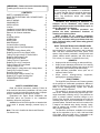
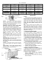
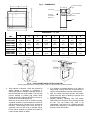
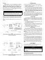
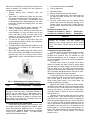
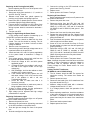
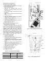
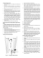
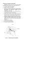
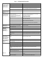
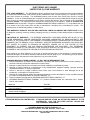
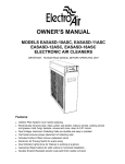
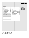
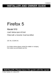
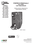
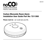
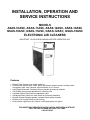
INSTALLATION, OPERATION AND
SERVICE INSTRUCTIONS
MODELS
ASAS-10ASC, ASAS-11ASC, ASAS-12ASC, ASAS-18ASC
GSAS-10ASC, GSAS-11ASC, GSAS-12ASC, GSAS-18ASC
ELECTRONIC AIR CLEANERS
IMPORTANT: PLEASE READ MANUAL BEFORE OPERATING UNIT
Features
• Lifetime Filter System never needs replacing
• Electronically removes dust, mites, pollen, pet dander, tobacco smoke, cooking smoke
•
•
•
•
•
•
•
and grease, mold, fungi, bacteria, and more down to 0.01 micron
Light Weight Aluminum Collecting Cells are durable and easy to maintain
Cell Guides ensure proper placement of collecting cells
Activated Carbon Filters remove unpleasant odors
Galvanized Steel Cabinet for solid vertical or horizontal installation
Durable Scratch-Resistant powder coat paint finish resists corrosion
Electronic Air Proving Switch for quick wiring
Dual Indicator Lights show Air Cleaner is working properly at a glance
FOR QUESTIONS REGARDING INSTALLATION, OPERATION & SERVICE,
CALL THE AIR CLEANER HOTLINE TOLL-FREE
1-800-267-8305
IMPORTANT: Please read entire instructions before
installing the Electronic Air Cleaner.
WARNING
Before beginning any installation or modification,
be certain that the main line electrical disconnect
switch is in OFF position. Electric shock could
result. Tag disconnect switch with suitable
warning labels.
CONTENTS
SAFETY CONSIDERATIONS
2
WHAT THE ELECTRONIC AIR CLEANER DOES
2
BENEFITS
2
HOW IT WORKS
2
COMPONENTS
2
INSTALLATION
3-5
Location
3
Installation Location With Humidifier
3
Installation Location With Air Conditioner
3
Electronic Air Cleaner Installation
3
Wiring
5
SYSTEM CHECK
5
OPERATION
5
WHITE DUST
5
MAINTENANCE
5
Cell and Prefilter Cleaning
5
Activated Carbon Filter Replacement
6
SERVICE
6-10
Testing Air Proving Switch (APS)
6
Replacing An Air Proving Switch (APS)
7
Testing For High Voltage AT Power Board
7
Replacing Performance Light
7
Replacing A Power Board
7
Testing The 24 V Transformer
7
Replacing The 24 V Transformer
8
Testing Voltage Of Power Board
8
Testing Voltage At Cell
9
Setting Approx. Voltage With High Voltage Meter
9
Testing Cell For Bad Contacts
9
Removing Power Box
9
Removing High Voltage Contact Tray
9
Replacing A Tungsten Ionizing Wire
10
TROUBLESHOOTING GUIDE
11
WARRANTY
12
SAFETY CONSIDERATIONS
Read and follow instructions carefully. Follow all
local electrical codes during installation. All wiring must
conform to local and national electrical codes. Improper
wiring or installation may damage Air Cleaner.
Understand the signal words WARNING and
CAUTION which are present in the Installation,
Operation & Service Instructions.
WARNING and CAUTION signifies a hazard which
could result in property damage, personal injury or
death.
Note: This unit is Certified for Shock and Electrical
Fire Hazard only.
Installation and servicing of Electronic Air
Cleaners can be hazardous. Only trained and
qualified service personnel should install, repair, or
service Electronic Air Cleaners.
Homeowners or untrained personnel can
perform the basic maintenance functions of
cleaning and replacing filters.
When working on air cleaning equipment,
observe precautions in the manual, labels attached
to the unit, and other safety precautions that may
apply. Follow all safety codes. Wear safety glasses
and work gloves.
WHAT THE ELECTRONIC AIR CLEANER DOES
Your High Efficiency Electronic Air Cleaner has
been designed to remove atmospheric and household
dust, coal dust, insecticide dust, mites, pollen, mold
spores, fungi, bacteria, pet dander, cooking smoke and
grease, tobacco smoke particles, and more down to
0.01 micron (.01 micron = 1/2,540,000 of an inch).
•
•
•
•
BENEFITS
Helps provide relief for allergy or asthma suffering.
Helps prevent damaging black dust from staining
walls and furnishings, reducing the amount of time
and money spent cleaning and redecorating.
Helps eliminate unpleasant odors (with use of
optional Carbon Filters).
Helps protect heating/cooling equipment,
prolonging the operating efficiency.
HOW IT WORKS
The High Efficiency Electronic Air Cleaner operates
on the principle of electrostatic precipitation. Millions of
airborne pollutants are carried through the return air
ducts of the heating/cooling system and treated
through four stages of filtration.
The prefilters (2) remove all large visible particles
such as lint. Smaller particles then pass through a twostage electrostatic collecting cell (2). First, particles are
given a powerful positive electrical charge by the
ionizing wires. Second, charged particles move into the
collecting area where they are attracted to a series of
grounded plates. Pollutants are held in this section like
a magnet until washed away during cleaning. Lastly,
clean air passes over activated carbon filters (3) for
odor removal (optional).
The Electronic Air Cleaner, available in four models
with air flow capacities of up to 1200, 1400 and 2000
CFM (2040, 2380 and 3400 m³/hr), is adaptable to all
residential forced air heating or cooling systems.
Table 1 — SPECIFICATIONS
MODEL
A/ GSAS-10ASC
A/ GSAS-11ASC
A/ GSAS-12ASC
A/ GSAS-18ASC
House Size Area
<2400 ft²
<222.96 m²
<3000 ft²
<278.70 m²
<3000 ft²
<278.70 m²
>3000 ft²
>278.70 m²
Airflow
up to 1200 cfm
up to 2039 m³/hr
up to 1400 cfm
up to 2379 m³/hr
up to 1400 cfm
up to 2379 m³/hr
up to 2000 cfm
up to 3398 m³/hr
Duct Size
16 x 20 in
40.5 x 51.0 cm
16 x 25 in
40.5 x 63.5 cm
20 x 20 in
51.0 x 51.0 cm
20 x 25 in
51.0 x 63.5 cm
Unit Weight
28.0 lbs
12.9 kg
30.0 lbs
13.5 kg
33.0 lbs
15.3 kg
38.0 lbs
17.5 kg
120 v 60 hz
Input Voltage
120 v 60 hz
120 v 60 hz
120 v 60 hz
Power Consumption
30 Watts
30 Watts
30 Watts
30 Watts
Upgrades Included
Carbon Filters (C)
Air Switch (AS)
Carbon Filters (C)
Air Switch (AS)
Carbon Filters (C)
Air Switch (AS)
Carbon Filters (C)
Air Switch (AS)
4 Collecting Cell Plates
1 Dirty Air
5 Carbon Filters (3)
Fig. 1
2 Prefilter
6 Clean Air to Heating/Cooling
System
3 Ionizing
Section
COMPONENTS
Cabinet: Constructed of heavy gauge galvanized
steel to resist corrosion and provide trouble-free
installation. Holes are provided to facilitate mounting to
the ductwork or air handling equipment.
Power Box: Removable. Contains the power switch,
performance indicator light, safety interlock switch,
high voltage power board and air proving switch.
The power board is uniquely equipped with a variable
resistor (potentiometer) to adjust high voltage output.
Output has been pre-set for optimum efficiency. As
voltage varies in extreme conditions of dryness,
humidity or proximity to hydro towers, raising or
lowering potentiometer allows for proper voltage
output.
Air Proving Switch (APS): Integrated. Automatically
cycles Air Cleaner on and off with the system fan. The
APS will detect airflow (fan on) and energize Air
Cleaner.
High Voltage Tray: Contains the contacts and wires to
supply high voltage to the collecting cells.
Collecting Cells: Consist of an ionizing section and a
plate section. The arrow on the cell must point toward
the system fan.
Prefilters: Constructed of aluminum mesh, to prevent
lint and large particles from entering the collecting
cells.
Carbon Filters: Remove odors. Must be replaced
every six months - not washable. Maximum of (3)
carbon filters can be used at same time.
Performance Indicator Light
ON/OFF Switch
Prefilters (2)
Power Box
Cabinet
Door
Fig. 2
Collecting Cells (2)
Activated
Carbon Filters
INSTALLATION
Location
The Air Cleaner must be installed in the return air
duct, as close to the fan compartment as possible. This
location provides the most even airflow across the
collecting cells and allows the Air Cleaner to keep the
system motor and blower clean. When choosing
location, there must be adequate room to wire the Air
Cleaner and remove prefilters, collecting cells and
power box.
Note: Once Air Cleaner has been installed, do not
allow the placement of any device such as a new hot
water heater, water softener, gas pipe, or electrical
cable to be put 2 ft. in front of or within 6 in. (15 cm)
from top of Air Cleaner, in order to allow removal of
filters and Air Cleaner parts, which are necessary for
maintenance or servicing.
Installation Location With Humidifier
A humidifier should be installed in the furnace
warm air duct. However, it may be installed in the
return duct without causing problems to the Air
Cleaner. Care must be taken to ensure that the
humidifier does not leak, as this may cause arcing and
a mineral deposit to build up on the collecting cells.
An atomizing type humidifier should be installed
downstream from the Air Cleaner. If the atomizing type
humidifier is installed upstream, high humidity, salts
and minerals may decrease the efficiency of the
collecting cells and cause service problems.
If the atomizing type humidifier must be installed
upstream, the following precautions should be taken:
1. Atomizing type humidifier must be installed as far
from the Air Cleaner as possible.
2. Collecting cells must be washed frequently to
prevent a mineral deposit build-up.
Installation Location With Air Conditioner
Whenever possible, the Air Cleaner should be
installed upstream of the cooling coil. This location will
clean the air before it reaches the evaporator coil.
Electronic Air Cleaner Installation
1. Remove existing equipment filter. Thoroughly
clean fan compartment and ductwork where Air
Cleaner is to be installed.
2. Open access door. Slide prefilters and collecting
cells out of cabinet.
Fig. 3 — DIMENSIONS
Performance Indicator
Light
Power Switch
AIR FLOW
Left to Right or
Right to Left
Air Proving Switch
Î
Handle
Door
DIMENSIONS — in (cm)
UNIT
A
B
C
D
E
F
G
H
ASAS-10ASC
GSAS-10ASC
21
(53.0)
17
(43.5)
23 1/4
(59.0)
13 1/8
(33.5)
20 3/4
(53.0)
1 1/4
(3.0)
23 3/4
(60.5)
2 3/8
(6.0)
ASAS-11ASC
GSAS-11ASC
21
(53.0)
17
(43.5)
26
(66.0)
13 5/8
(34.5)
24
(61.0)
1
(2.5)
26 1/2
(67.5)
2 1/8
(5.5)
ASAS-12ASC
GSAS-12ASC
25 7/8
(66.0)
22
(56.0)
21 1/4
(54.0)
18
(46.0)
18 3/4
(47.5)
1 1/4
(3.0)
21 3/4
(55.0)
2 3/8
(6.0)
ASAS-18ASC
GSAS-18ASC
25 7/8
(66.0)
22
(56.0)
26
(66.0)
18
(46.0)
23 1/2
(59.5)
1 1/4
(3.0)
26 1/2
(67.5)
2 3/8
(6.0)
Fig. 4 — AIR CLEANER INSTALLATION LOCATION
Allow 24 in (600 mm) clearance for cleaning air cleaner. Allow 6 in. (150 mm) clearance for power box removal.
3. Place cabinet in ductwork. Holes are provided to
attach cabinet to ductwork or equipment. If
adjoining ductwork is flanged, install the screws so
that screw heads are inside cabinet. This will help
prevent damage to prefilter and carbon filters
during removal for cleaning. NEVER put screws or
rivets into the removable power box.
When the air duct does not fit Air Cleaner opening,
a gradual transition is recommended to reduce air
turbulence through Air Cleaner and to increase its
efficiency. There should not be more than 20º of
expansion used on each side of transition fitting.
Do not reduce ductwork to a smaller Air Cleaner or
it will increase velocity of airflow.
4. If Air Cleaner is installed adjacent to an elbow or
angle fitting, turning vanes are recommended to
improve air distribution across the collecting cells.
5. After Air Cleaner has been secured, seal seams
airtight with duct tape or caulking to prevent dust
from entering the system.
6. Replace prefilters, collecting cells and carbon
filters. Make sure arrow on cell is pointing towards
the fan. The cell handle may need to be
repositioned if the airflow is in a different direction
than the left to right set up. The handle should face
the door. Close access door.
Wiring
Wiring should only be performed by qualified
personnel only. All wiring must comply with all
applicable codes and standards. The voltage of the
power source must match the voltage indicated on the
Air Cleaner. The Air Cleaner should operate ONLY
when the system fan is running. Make sure the Air
Cleaner is properly grounded.
WARNING
Electrical shock can cause injury or death. Be certain
main line disconnect switch is off before wiring.
Wire the Air Cleaner directly to the 120 V power
source. The APS will power the Air Cleaner when there
is sufficient airflow to activate the sensor. See Fig 5 &
6.
Note: The power switch will be lit even if there is no
airflow.
SYSTEM CHECK
Perform the following system check before operation.
1. Replace prefilters, collecting cells and carbon
filters. Close access door.
2. Turn Air Cleaner power switch ON. Ensure system
fan is operating. Both the power switch light and
performance indicator light should be lit. The power
switch light indicates the Air Cleaner has unit
voltage. The performance indicator light shows that
the Air Cleaner is operating.
Note: There may be some arcing or snapping sounds
from the collecting cells. This is normal when the unit is
new. In about 2 weeks, as the sharp edges of the cells
become smoother, the arcing will disappear.
OPERATION
The Air Cleaner will run as long as there is airflow
through the ducts. The Air Cleaner will not run if the
system fan is off. For proper operation, follow these
simple steps:
1. Run heating/cooling system fan continuously, and
on low speed if available.
2. Remove furniture or carpets which block return air
grilles throughout your house, so that air moves
freely to the furnace/ air conditioner.
3. Check for proper operation of the system fan.
WHITE DUST
Fig. 5
Models ASAS-10ASC/GSAS-10ASC, ASAS-11ASC/GSAS-11ASC
(with Air Proving Switch)
After installation of the Air Cleaner, you may notice
some white dust on tabletops and shelves. Most large
particles such as lint, are too heavy to remain airborne
and tend to settle quickly, never reaching the air
cleaner.
This white visible dust is normally referred to as
“clean dust.” As the Air Cleaner is removing the dark
and staining particles from the air, the lint will also be
cleaner.
Lint dust is most noticeable on dark furnishings; in
homes containing new carpeting; and where there is a
lot of household traffic from occupants and pets. To
reduce lint dust, use continuous fan operation and keep
return vents unrestricted to create an efficient airflow.
Note: The Air Cleaner does NOT produce more lint or
dust.
MAINTENANCE
It is important to follow a scheduled maintenance for
maximum performance of the Air Cleaner.
CAUTION
Make sure to turn Air Cleaner and system fan OFF
before performing any maintenance or removing any
components.
Fig. 6
Models ASAS-12ASC/GSAS-12ASC, ASAS-18ASC/GSAS-18ASC
(with Air Proving Switch)
Cell And Prefilter Cleaning
The collecting cells and prefilters must be cleaned on a
regular basis for the Air Cleaner to function at its peak
efficiency. The frequency of cleaning will vary from one
house to another. On average, the cells should be
cleaned every 3 months.
1. Remove access door, collecting cells and
prefilters.
2. Place cells in a laundry tub. Rinse with hot water
and spray completely with DAX Detergent (or a
non-chlorine, non-corrosive, non-abrasive liquid
household detergent. Allow detergent to run down
both sides of plates and ionizing wires. Let stand
for 5 minutes.
3. Rinse cells well with hot water (maximum 120°
F/49°C). Repeat washing process 2-3 times.
4. If dirt remains, fill up laundry tub with water and
DAX Detergent (1/2 cup), and dunk cells up and
down until water is dirty. Let cells soak in the
solution for 30 minutes. Then rinse cells well with
hot water (maximum 120°F/49°C).
5. Tilt cells on 45° angle on their short side, with
arrows pointing sideways. Allow to dry completely,
approximately 10-24 hours.
6. To wash prefilters, spray with DAX Detergent, rinse
and let dry. Do not wash in the same water as
collecting cells.
7. Place cells and prefilters back into cabinet. Close
door and turn power switch ON. If the performance
light does not come on or arcing occurs, turn Air
Cleaner OFF, remove cells and allow more drying
time.
Fig. 7 — DAX Detergent and Carbon Filters are
available from your installer or dealer.
DAX
32 oz Spray Bottle
Part #9900
CAUTION
Damage to cells may occur if improperly handled or
washed. Do not wash cells in a dishwasher. Never
use any object to clean between the cell plates, as
this may cause damage to plates or ionizing wires.
Never place cell in oven to dry. The edges of the cell
may be sharp - handle with care.
Activated Carbon Filter Replacement
Carbon filters help remove odors from the air. If the
Air Cleaner has been equipped with optional carbon
filters, they should be replaced every 3 - 6 months.
Filters are NOT washable. Replacements are available
through your installer or dealer. To replace filters,
perform the following functions:
1.
2.
3.
4.
5.
Turn Air Cleaner power switch OFF.
Turn off system fan.
Open access door.
Remove collecting cells from Air Cleaner.
Pull out used carbon filters. If the carbon filters do
not slide out easily, tilt them on a 45° angle and
they will fall out.
6. Put new carbon filters into Air Cleaner. Space
filters evenly across the discharge opening of Air
Cleaner. Never put more than 3 carbon filters in
the Air Cleaner, as this may cause a problem with
airflow.
Replacement Carbon Filters:
A/ GSAS-10, A/ GSAS-11 Set of 3
Part #1156-3
A/ GSAS-12, A/ GSAS-18 Set of 3
Part #1856-3
SERVICE
WARNING
Electronic Air Cleaners use high voltage (low
amperage). Only trained personnel should perform
service. Use caution. Electric shock can cause injury
or death.
Testing Air Proving Switch (APS)
The APS sensor must protrude through the plastic
bushing to work effectively. The sensor is very
sensitive and operation may be affected by cold
basement temperatures, an air exchanger, or a fresh
air duct connected to the cold air return just upstream
of the Air Cleaner.
The APS uses a Triac in its output circuit, which
affects the voltage sine wave. Using a regular digital
voltmeter will give a false reading. To check the output
from the APS, use a true RMS (root mean square)
meter to measure the output at terminals 1 and 4 of the
APS. The output should be between 105 and 115 VAC,
depending on the airflow across the sensor.
A neon lamp may be used to test the output of the
APS. Place the leads of the lamp across terminals 1
and 4 of the APS, or across the 120 V input of the
single output power board. If the lamp lights, the
voltage is sufficient for operation.
When the Air Cleaner is turned on without airflow,
the APS sensor heats up and after 30 seconds, opens
the circuit to turn off the power board. When the fan
starts up (the sensor is cooled), the circuit will close,
the power board is turned on, and the performance
light will come on.
The light on the power switch will be lit even when
the APS is open. If the power board fails to come on
with the fan on, check that the sensor is properly set
down, through the plastic bushing, in front of the power
box. To check the APS for proper operation, turn the
unit on and activate. The power board should come on
immediately, and then turn off in 30 seconds as the
sensor heats up. To check sensor, blow directly on it
lightly. This should activate the power board within 10
seconds. Service the sensor carefully. The sensor
leads are 120 V.
Replacing An Air Proving Switch (APS)
Before replacing the APS, turn off the power to the
Air Cleaner at the source.
1. Disconnect wiring from terminals 1, 2, 3, and 4 on
the APS. See Fig. 5 and 6.
2. Release circuit board from plastic spacers by
pinching end of spacer and pulling board out.
3. Install new APS on plastic spacers. Ensure sensor
protrudes slightly through plastic bushing.
4. Connect wiring to terminals on APS. Wiring from
power source is connected to terminals 2 and 3.
Wiring to power board is connected to terminals 1
and 4.
5. Test the new APS.
Testing For High Voltage At Power Board
A high voltage meter capable of measuring up to
10,000 VDC is required to test the voltage.
1. The Air Cleaner should be ON with the door
closed. The unit fan should be running. The Air
Cleaner should be on at least 5 minutes to allow
voltage to stabilize.
2. Remove cover from power box.
3. Connect the ground of the high voltage meter to an
unpainted surface in the power box.
4. Check terminals HV1 and HV2 (where applicable)
on the power board to determine if voltage is
present.
5. If no voltage present, remove both cells from the
Air Cleaner and replace access door.
a. Check the voltage at HV1 and HV2 (where
applicable) again.
b. If voltage is present, the problem is with one of
the cells or the copper contact on the high
voltage tray.
c. With a flashlight, look into the cabinet to check
condition of the copper contacts.
d. If the contacts are not bent, replace one cell
and retest voltage. If cell is OK, test the other
cell. If the problem is with a cell, see
Troubleshooting Guide.
e. Check the APS to make sure that it is
functioning correctly.
f. Check the transformer to make sure power is
being supplied to the Air Cleaner.
6. If there is voltage present, but the performance
light does not come on, replace light.
7. High voltage can be adjusted with high voltage
potentiometer if required.
Replacing Performance Light
Before replacing performance light, turn off power
to the Air Cleaner at the source.
1. Remove the power box cover.
2. Disconnect the performance light wiring connected
to the LED terminals on the power board.
3. Push the light out through the front of the power
box.
4. Push the new light into the power box.
5. Connect the wiring to the LED terminals on the
power board. See Fig. 5 and 6.
6. Replace cover.
7. Return power to Air Cleaner. Test light.
Replacing A Power Board
Before replacing power board, turn off power to the
Air Cleaner at the source.
1. Remove the power box cover.
2. Disconnect wiring from the LED, HV1 and 120
VAC power board terminals (A/ GSAS-10 and A/
GSAS-11) or LED, HV1, HV2 and 24 V terminals
(A/ GSAS-12 and A/ GSAS-18) and ground. See
Fig 5 & 6.
3. Remove the 2 hex nuts from the power board.
4. Release the power board from the 2 plastic board
spacers, by pinching the end of the spacers and
pulling the board out.
5. Push new board onto spacers. Make sure spacers
click into place to hold down board.
6. Screw on 2 hex nuts saved from Step 3. Ensure
the star washer is in place over the steel spacer for
proper grounding.
7. Reconnect wiring to LED, HV1 and 120 VAC (A/
GSAS-10 and A/ GSAS-11) terminals or LED,
HV1, HV2, and 24 V terminals (A/ GSAS-12 and A/
GSAS-18) and ground on the new power board.
8. Replace power box cover.
9. Return power to Air Cleaner. Test power board.
Note: Although the power board has been set before
shipping, it may be necessary to reset the voltage to
the correct load for optimum efficiency. Refer to
Testing Voltage At Power Board section for more
information.
Testing The 24 V Transformer
(A/ GSAS-12 and A/ GSAS-18 Only)
1. The Air Cleaner should be ON. The system fan
should be running. The access door should be
closed.
2. Remove power box cover.
3. Disconnect the leads of the 24 V transformer from
the power board. See Fig. 6.
4. Measure voltage across leads with a voltmeter.
Voltage should read 24 - 27 VAC.
5. If no voltage present, check the operation of the
APS.
6. Before replacing transformer, check the resistance
of the power board input. Input should read above
40 Kohm. If resistance is below 40 Kohm, the
power board may be the cause of the transformer
failure.
7. Reconnect leads to power board.
8. Replace power box cover.
Replacing The 24 V Transformer
(A/ GSAS-12 and A/ GSAS-18 only)
Before replacing 24 V transformer, turn off power
to the Air Cleaner at the source.
1. Remove power box cover.
2. Disconnect the secondary leads from the
transformer to the 24 V terminals on the power
board. See Fig. 6.
3. Cut the primary leads (to the APS) close to the
transformer.
4. Remove the 2 hex head nuts from the transformer
studs.
5. Remove transformer.
6. Place new transformer over studs and re-install 2
hex head nuts to lock into place.
7. Connect secondary leads (white) to the 24 V
terminals on the power board.
8. Wire nut primary leads from APS (cut in Step 3) to
primary leads from transformer.
9. Replace power box cover.
10. Turn on power to the Air Cleaner and test.
Testing Voltage Of Power Board
Voltage on the power board may drop below
required level when installation area is too damp, too
cold, or if there is a leakage of water from a humidifier.
Voltage on power board may be too high when
installation area is too dry or too hot, or home is in
close proximity to hydro towers or situated in remote
farm land areas. By adjusting the HV ADJ
potentiometer, the voltage can be set to optimum level.
A high voltage meter capable of measuring 10,000
VDC is required. To test and adjust voltage level,
perform the following procedure:
1. Turn the Air Cleaner OFF.
2. Remove the power box cover.
3. Connect the ground of the high voltage meter to an
unpainted surface in the power box.
4. Turn ON the Air Cleaner and wait 5 minutes before
checking voltages to allow voltages on cells to
stabilize.
5. Measure the voltages at HV1 and HV2 (where
applicable) on the power board. See Fig. 8
6. Adjust the HV ADJ potentiometer until the voltage
reading matches the voltage in Table 2.
7. Turn OFF the Air Cleaner.
8. Remove the high voltage meter.
9. Replace the power box cover.
10.Turn ON the Air Cleaner.
High Voltage Probe
Probe
Fig. 8 — Testing Voltage At Power Board
Safety Interlock
Grounded
Area
Probe
Screwdriver
Table 2 — Power Board Voltage Settings
Model
Maximum Voltages on
Plates (K VDC)
Maximum Voltage on
Ionizer (K VDC)
ASAS-10ASC, ASAS-11ASC
GSAS-10ASC, GSAS-11ASC
6.2 - 6.5 (HV1)
6.2 - 6.5 (HV1)
ASAS-12ASC, ASAS-18ASC
GSAS-12ASC, GSAS-18ASC
4.8 - 5.2 (HV1)
7.2 - 7.8 (HV2)
Fig. 9 — Testing Voltage At Cell
Testing Voltage At Cell
1. Open access door to Air Cleaner. Air Cleaner will
shut off.
2. Insert a thin shafted screwdriver 2 to 3 inches into
the hole in the round end plate insulator. See Fig.
9.
3. Attach the ground of the high voltage meter on to a
grounded area of the cell.
4. Place the tip of the high voltage probe on the shaft
of the screwdriver. Press down the safety interlock.
Power to Air Cleaner will come on.
5. Wait until the voltage stabilizes, then take a
reading. Adjust the HV ADJ potentiometer until the
voltage reading matches the voltage in Table 2. If
the voltage fails to stabilize or jumps up and down
by more than 100 V, there may be a bad contact in
the cell or a bad contact between the cell contacts
and the high voltage contacts on the contact tray.
6. Let up on the safety interlock. Remove high
voltage meter.
7. Remove screwdriver and close access door.
Setting Approximate Voltage Without High Voltage
Meter
A high voltage meter should be used. If one is not
available, this method can be used. This will only set
an approximate voltage. After using this method, the
voltage should be reset with a high voltage meter as
soon as possible.
1. Remove power box cover.
2. Turn the HV ADJ potentiometer fully clockwise. Air
Cleaner may arc or snap at this point.
3. Turn the HV ADJ potentiometer counterclockwise
slowly until the arcing and snapping stops.
4. Replace power box cover.
Testing Cell For Bad Contact
Screwdriver
Fig. 10 — Testing For Bad Contacts
1. Open access door to Air Cleaner.
2. Place a screwdriver between plates of the cell, or
place a small screwdriver into the hole in the end
plate insulator and short with another screwdriver
to cell end plate. See Fig. 10.
3. Press safety interlock switch to start Air Cleaner.
There should be an initial snap when the plates are
shorted, then no sound. If a hissing occurs, then
there is a bad contact. Look along the top of the
cell, with the short still in place. If there is a small
arc between the cell top and copper contact, then
that is the bad contact. Pull cell out and gently pull
copper contact down.
If an arc is not seen and there is a bad contact,
then the problem may be the internal contact of the
cell. With an ohmmeter, check continuity between
the top disc contact and the first plate. the reading
should be close to 0 ohms. If not, bend the contact
to touch the plate. On dual voltage units (three disc
contacts), there are two internal contacts, one on
each side. Test each contact.
4. Let up on safety interlock.
5. Remove screwdrivers.
6. Close access door.
Removing Power Box
1. Turn the main system switch off or disconnect the
power source.
2. Remove the power box cover.
3. Disconnect the source wires to the Air Cleaner.
Cap off the wires so the system can still be
operated.
4. Disconnect high voltage leads from power board.
5. Remove three nuts holding the power box to the
cabinet. Do not remove the nut at the center front,
located between the switch and the light. This nut
holds the high voltage tray onto the power box.
Removing High Voltage Contact Tray
1. Turn off power to Air Cleaner.
2. Remove cells, prefilters and carbon filters from Air
Cleaner.
3. Remove the high voltage wires from the power
board.
4. Remove the four screws securing the contact tray
to the cabinet. Two screws are located at the rear
of the cabinet, behind the power box. The other
two screws are located behind the door at the front
of the cabinet. Support the tray as you remove the
screws. As you lower the tray, feed the high
voltage wire(s) down through the plastic wire
bushing.
5. To reinstall the contact tray, reverse the procedure.
When reconnecting the high voltage wire(s) to the
power board, attach the wire with clear or no
sleeving to HV1. The wire with the blaack sleeve (if
used) is connected to HV2 on the power board.
6. To reinstall high voltage contact tray, reverse
above procedure.
Replacing A Tungsten Ionizing Wire
Replacement wires are cut to the correct length
and have eyelets at each end for easy replacement.
1. Turn OFF power to Air Cleaner.
2. Remove cell from Air Cleaner.
3. Remove all parts of broken wire, as well as spring
and S-hook. If necessary, cell may be used
temporarily with one wire missing until a
replacement is received.
4. Using needle-nose pliers, place spring hook in the
hole of the ionizing bar near cell top.
5. Place eyelet of wire over the S-hook and place Shook into hole on ionizing bar on other side of cell.
Keep wire tight to ensure S-hook remains in hole.
6. Using the needle-nose pliers, grab the end of the
spring and stretch towards loop in wire. Place
eyelet in wire over spring hook and release spring.
See Fig. 11.
7. Install cell in Air Cleaner.
8. Return power to Air Cleaner.
9. Test cell for proper operation.
Spring
Ionizing Bar
Wire
Fig. 11 — Replacing An Ionizing Wire
Table 3 — TROUBLESHOOTING GUIDE
PROBLEM
PROBABLE CAUSE
REMEDY
System fan is not on.
Turn system fan on.
Wiring improperly connected.
Check wiring.
Defective power switch.
Check power switch for continuity with multimeter. Replace if defective.
Defective safety interlock.
Remove door and press safety interlock with a screwdriver. If lights
come on, bend interlock lever towards front and close door.
Power (120 V) is not provided to device.
Check power wiring with multimeter.
Power light is off and
performance indicator
light is on.
Defective power light.
Replace power switch.
Unit does not function
correctly. Power light is
on and performance
indicator light is off.
Short in cells due to:
1. Broken ionizing wire(s).
2. Large particles wedged between cell plate(s).
3. Cells washed recently and are still wet.
4. Round end plate insulator is burnt or melted.
5. Cell plate(s) are bent.
1.
2.
3.
4.
5.
Unit does not function
correctly. Power light
and performance
indicator light are off.
Defective performance indicator light.
Determine whether high voltage is present by testing power box. If
present, replace indicator light.
Defective power board.
Adjust high voltage potentiometer on power board clockwise. If high
voltage is not present, replace power board.
Air Proving Switch (APS) sensor is burnt out.
Remove power box and connect with 120 V. Lightly blow on APS at the
bottom of power box. If light does not come on, replace APS.
Off board 24 V transformer is not working.
Verify output of transformer. Replace if necessary.
Internal cell contacts are not touching plates.
Cell makes loud
hissing noise or causes Copper contacts on high voltage tray not making
radio interference.
good connection on cell.
Cells arcing
excessively
(power light and
performance
indicator light on).
Ozone odor
Test contact and repair.
With needle-nose pliers, gently pull contacts down or replace contacts.
Cells wet from washing.
Allow cells to dry completely.
Particle(s) lodged in cell or broken ionizing wire.
Wash cell. Shake particle out of cell. Replace wire, if necessary.
Ducts were not cleaned prior to installation of air
cleaner.
Clean ducts.
Cell plate(s) are bent.
Remove cells and adjust to original spacing using needle-nose pliers.
Voltage is too high.
Adjust high voltage potentiometer on power board counter-clockwise.
Humidifier (if installed) is leaking water on air
cleaner.
Repair humidifier. If possible, move humidifier to different location.
Cells arcing excessively Contacts on high voltage tray are broken or bent
upward.
at top of cell near
copper contacts (power
light and performance
indicator light on).
Cells not collecting dirt
(power light and
performance indicator
light on).
Remove wire or wire fragments, spring and S-hook. Replace.
Shake large particles out or wash cell.
Allow cells to dry completely.
Replace end plate insulator.
Straighten plates with pliers.
If possible, pull down contacts with needle-nose pliers or remove high
voltage tray and replace contacts.
Arrow on cell(s) not pointing towards fan blower.
Reposition cells.
System fan is on “Automatic” setting (air cleaner
not on continuously).
Use “Fan On” system fan setting for continuous fan operation.
Not enough voltage on collecting cells.
Adjust high voltage potentiometer clockwise on power board.
Cell plate(s) are bent.
Straighten with needle-nose pliers.
Loose or broken ionizing wire(s).
Replace wires.
Dirty cells.
Wash cells.
Air Cleaner is on when system fan is not running. Check operation and wiring of air switch and air cleaner.
Air switch not activated or air cleaner wired
incorrectly.
White dust
Incoming voltage is higher than 120 V.
Adjust high voltage potentiometer counter-clockwise on power board.
Air Cleaner is oversized for house. Not enough
airflow to cover surface area of cells.
Use correct size of Air Cleaner.
Home is extremely dry.
Repair or install central humidifier.
Clean lint dust too heavy to remain airborne.
Keep fan running continuously. Ensure that return air grilles are not
obstructed.
Gaps around Air Cleaner.
Seal or use duct tape around Air Cleaner cabinet.
ELECTRONIC AIR CLEANER
LIMITED FIVE (5) YEAR WARRANTY
FIVE YEAR WARRANTY - This GOODMAN product is warranted to be free from electrical and mechanical defects
in material and workmanship, under normal use and maintenance within its listed capacity, for a period of FIVE (5)
years from the date of purchase. The GOODMAN product must not have been moved from the site of original
installation. A new or remanufactured part to replace the defective part will be provided without charge for the part
itself, through an authorized GOODMAN service dealer, provided the defective part is returned to the GOODMAN
distributor prepaid. The replacement part assumes the unused portion of the warranty. Proof of Purchase and
Installation must be provided. Failing this, GOODMAN MANUFACTURING COMPANY, L.P. will guarantee the unit
for a period of sixty (60) months from the date of manufacture, according to the manufacturer’s records. The
warranty does not include the prefilters or carbon filters.
THIS WARRANTY DOES NOT INCLUDE ANY ADDITIONAL LABOR ALLOWANCE OR OTHER COSTS incurred
for diagnosis, repairing, removing, installing, shipping, servicing, or handling of either defective parts or replacement
parts.
LIMITATIONS OF WARRANTY - THE EXPRESS WARRANTIES CONTAINED HEREIN ARE IN LIEU OF ALL
OTHER WARRANTIES. IMPLIED WARRANTIES INCLUDING WARRANTIES OF MERCHANTABILITY ARE
LIMITED TO THE DURATION OF THE WARRANTY DESCRIBED HEREIN. CONSEQUENTIAL OR INCIDENTAL
DAMAGES FOR THE BREACH OF ANY WARRANTY WHETHER EXPRESSED OR IMPLIED, INCLUDING BUT
NOT LIMITED TO LOSSES TO PERSONS OR PROPERTY ARISING OUT OF THE FAILURE OF THIS
EQUIPMENT TO OPERATE FOR ANY REASON WHATSOEVER ARE EXCLUDED. THE EXPRESSED
WARRANTIES MADE IN THIS WARRANTY ARE EXCLUSIVE AND MAY NOT BE ALTERED, ENLARGED, OR
CHANGED BY ANY DISTRIBUTOR, DEALER OR OTHER PERSON WHATSOEVER.
Some states do not allow limitations on how long an implied warranty lasts or the exclusions of consequential or
incidental damages, so the above limitations and exclusions may not apply to you. This warranty gives you specific
legal rights and you may also have other rights which vary from state to state.
GOODMAN MANUFACTURING COMPANY, L.P. WILL NOT BE RESPONSIBLE FOR:
1. Normal maintenance as outlined in the Installation, Operation And Service Instructions including cleaning of
electronic collecting cells and/or replacement of carbon filters.
2. Damage or repairs required as a consequence of faulty installation or application by others.
3. Damage or repairs needed as a consequence of any misapplication, negligent handling, improper servicing,
unauthorized alteration, or improper operations.
4. Failure to start due to voltage conditions, blown fuses, open circuit breakers or other damages due to the
inadequacy or interruption of electrical service.
5. Damage as a result of floods, winds, fires, lightning, accidents, corrosive atmosphere, or other conditions beyond
the control of GOODMAN MANUFACTURING COMPANY, L.P.
6. Parts not supplied or designated by GOODMAN MANUFACTURING COMPANY, L.P.
7. GOODMAN MANUFACTURING COMPANY, L.P. products installed outside the continental U.S.A., Alaska,
Hawaii, and Canada.
Model No.
Serial No.
Date Of Installation
Installed By
Owner’s Name & Address
RETAIN THIS CERTIFICATE WITH YOUR VALUABLE DOCUMENTS
ATTENTION INSTALLING CONTRACTOR:
IF FAILURE SHOULD OCCUR, DO NOT RETURN PRODUCT TO THE
DISTRIBUTOR. CALL THE TOLL-FREE HOTLINE 1-800-267-8305
FOR TECHNICAL ASSISTANCE.
GOODMAN MANUFACTURING COMPANY, L.P.
2550 North Loop West, Suite 400, Houston, Texas 77092
FOR MORE INFORMATION, CALL THE AIR CLEANER HOTLINE TOLL FREE
1-800-267-8305
nngoodea.pub
02/08