1
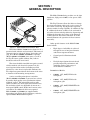
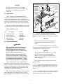
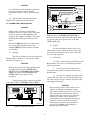
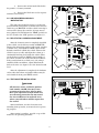
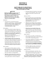
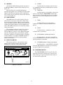
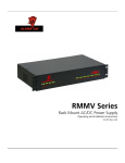
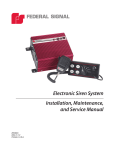
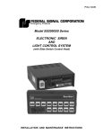
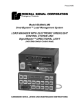
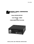
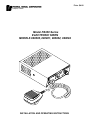
Price $4.00
Model PA300 Series
ELECTRONIC SIREN
MODELS 690000, 690001, 690002, 690004
INSTALLATION AND OPERATING INSTRUCTIONS
LIMITED WARRANTY
The Signal Division, Federal Signal Corporation (Federal), warrants each
new product to be free from defects in material and workmanship, under
normal use and service, for a period of two years on parts replacement and
one year on labor from the date of delivery to the first user-purchaser.
During this warranty period, the obligation of Federal is limited to repairing
or replacing, as Federal may elect, any part or parts of such product which
after examination by Federal discloses to be defective in material and/or
workmanship.
Federal will provide warranty for any unit which is delivered, transported
prepaid, to the Federal factory or designated authorized warranty service
center for examination and such examination reveals a defect in material
and/or workmanship.
This warranty does not cover travel expenses, the cost of specialized
equipment for gaining access to the product, or labor charges for removal
and re-installation of the product. Lamps, flash tubes, or batteries are not
covered under warranty.
This warranty does not extend to any unit which has been subjected to abuse,
misuse, improper installation or which has been inadequately maintained,
nor to units which have problems relating to service or modification at any
facility other than the Federal factory or authorized warranty service
centers.
THERE ARE NO OTHER WARRANTIES, EXPRESSED OR IMPLIED,
INCLUDING BUT NOT LIMITED TO, ANY IMPLIED WARRANTIES
OF MERCHANTABILITY OR FITNESS FOR A PARTICULAR
PURPOSE. IN NO EVENT SHALL FEDERAL BE LIABLE FOR ANY
LOSS OF PROFITS OR ANY INDIRECT OR CONSEQUENTIAL
DAMAGES ARISING OUT OF ANY SUCH DEFECT IN MATERIAL OR
WORKMANSHIP.
SECTION I
GENERAL DESCRIPTION
The Model PA300 Series can drive one 11-ohm
impedance, high power (100W) or low power (58W)
speaker.
The Tap II feature allows the driver to change
the siren sound from wail to yelp (or vice-versa) via
the vehicle’s horn ring. Tap II provides especially
effective traffic clearing capability. In addition to Tap
II, additional alternate sounds can be activated in
two other selector switch positions by depressing and
holding the horn ring for as long as the alternate
sound is desired. The charts in Section IV of this
manual illustrate the operation of these features
more fully.
Other special features of the Model PA300
Series include:
290A4452-01
Figure 1-1. Model PA300 Series Electronic Siren.
The Federal Model PA300 Series (figure 1-1) is a
precision built, efficient and economical, full-featured
electronic siren of advanced design. It provides wail,
yelp, hi-lo (Models 690000 and 690001) or priority
(Models 690002 and 690004) siren tones, as well as
the Tap II feature, public address (PA), radio rebroadcast and an air horn sound.
The siren should be installed in negative ground
vehicles with 12-volt electrical systems. It is protected against failure modes (including reversed
polarity) by a fuse that is replaceable without tools.
No components protrude from the bottom of the siren
to interfere with mounting arrangements.
•
High degree of reliability is achieved
through the use of integrated circuits
and silicon output transistors.
•
Control panel is illuminated with
LED's.
•
Newly designed printed circuit board
provides improved performance and
durability under a wide range of
environmental conditions.
PA300 Series Models:
A noise-cancelling microphone is wired-in
(Models 690000 and 690002) to prevent loss or theft.
It provides high quality voice reproduction without
feedback “squeal”. The microphone push-to-talk
switch overrides any siren signal for instant PA use.
PA and radio volume are adjustable by means of a
front panel GAIN control. Radio inter-connect wires
are built-in. No additional cables are required.
Models 690001 and 690004 are supplied with a
microphone jack. To use the PA functions, order the
optional Model MNCT-SB microphone.
-1-
•
690000 12V, 100W, HI-LO with
microphone
•
690001 12V, 100W, HI-LO with
microphone jack
•
690002 12V, 100W, PRIORITY with
microphone
•
690004 12V, 100W, PRIORITY with
microphone jack
SECTION II
SPECIFICATIONS
Input Voltage ...............................................................
11VDC to 15VDC.
Polarity .........................................................................
Negative ground only.
Standby Current (MANUAL) ......................................
60ma (typical).
Operating Temperature Range ...................................
-30°C to +65°C.
Operating Current (Wail mode) ..................................
10 amperes, max. (@ 13.6VDC)
(11 ohm load, @ high power)
Frequency Range (typical) ..........................................
725 to 1800Hz.
Cycle Rate (typical) ......................................................
Wail- 15 cycles/min.
Yelp- 220 cycles/min.
Hi-Lo- 70 cycles/min. (690000 and 690001)
Priority 1300 cycles/min. (690002 and 690004)
Voltage Output (approx.) .............................................
64V peak-to-peak.
Dimensions (HWD) ......................................................
2-1/2" (6.35cm) x 6-1/2" (16.51cm) x 8-1/2" (21.59cm).
Net Weight (incl. microphone) ....................................
4-1/2 lbs. (2.04kg).
Shipping Weight ..........................................................
6-1/2 lbs. (2.94kg).
NOTE
The following parameters were obtained with the
radio input potentiometer and GAIN control set
at maximum.
Audio Frequency Range ..............................................
300 to 10,000Hz.
Harmonic Audio Distortion (300-3,000Hz) .................
10% max. all power levels from 1/2 to 50 watts (frequency
response ±3dB).
Input Impedance (Radio) .............................................
2000 ohms.
Input voltage required to obtain 20VRMS across
speaker load (Radio) ..................................................
0.30VRMS.
-2-
SECTION III
INSTALLATION
SAFETY MESSAGE TO INSTALLERS
OF
ELECTRONIC SIRENS
•
Sound output will be severely reduced if any objects are
in front of the speaker. If maximum sound output is
required for your application, you should ensure that the
front of the speaker is clear of any obstructions.
•
Install the speaker(s) as far forward on the vehicle as
possible, in a location which provides maximum
signaling effectiveness and minimizes the sound
reaching the vehicle’s occupants. Refer to the National
Institute of Justice guide 500-00 for further information.
Qualifications
•
To properly install an electronic siren: you must have a
good understanding of automotive electrical procedures
and systems, along with proficiency in the installation
and service of safety warning equipment. Always refer to
the vehicle’s service manuals when performing
equipment installations on a vehicle.
Mounting the speakers behind the grille will reduce the
sound output and warning effectiveness of the siren
system. Before mounting speakers behind the grille,
make sure the vehicle operators are trained and
understand that this type of installation is less effective
for warning others.
•
Sound propagation and warning effectiveness will be
severely reduced if the speaker is not facing forward.
Carefully follow the installation instructions and always
install the speaker with the projector facing forward.
•
DO NOT install the speaker(s ) or route the speaker
wires where they may interfere with the operation of air
bag sensors.
•
Installation of two speakers requires wiring speakers in
phase.
•
Never attempt to install aftermarket equipment, which
connects to the vehicle wiring, without reviewing a
vehicle wiring diagram - available from the vehicle
manufacturer. Insure that your installation will not
affect vehicle operation and safety functions or circuits.
Always check vehicle for proper operation after
installation.
•
DO NOT install equipment or route wiring or cord in the
deployment path of an air bag.
•
Locate the control head so the vehicle, controls, and
microphone can be operated safely.
•
When drilling into a vehicle structure, be sure that both
sides of the surface are clear of anything that could be
damaged.
WARNING
The lives of people depend on your proper installation
and servicing of Federal products. It is important to
read and follow all instructions shipped with the
products. In addition, listed below are some other
important safety instructions and precautions you
should follow:
Before Installation
•
Sound Hazards
•
Your hearing and the hearing of others, in or close to
your emergency vehicle, could be damaged by loud
sounds. This can occur from short exposures to very loud
sounds, or from longer exposures to moderately loud
sounds. For hearing conservation guidance, refer to
federal, state, or local recommendations. OSHA
Standard 1910.95 offers guidance on “Permissible Noise
Exposure.”
•
All effective sirens and horns produce loud sounds (120
dB) that may cause permanent hearing loss. Always
minimize your exposure to siren sound and wear hearing
protection. Do not sound the siren indoors or in enclosed
areas where you and others will be exposed to the sound.
•
Federal Signal siren amplifiers and speakers are
designed to work together as a system. Combining a
siren and speaker from different manufacturers may
reduce the warning effectiveness of the siren system and
may damage the components. You should verify or test
your combination to make sure the system works
together properly and meets federal, state and local
standards or guidelines.
During Installation
•
•
DO NOT get metal shavings inside the product. Metal
shavings in the product can cause the system to fail. If
drilling must be done near the unit, place an ESD
approved cover over the unit to prevent metal shavings
from entering the unit. Inspect the unit after mounting
to be sure there are no shavings present in or near the
unit.
After Installation
DO NOT connect this system to the vehicle battery until
ALL other electrical connections are made, mounting of
all components is complete, and you have verified that
no shorts exist. If wiring is shorted to vehicle frame,
high current conductors can cause hazardous sparks
resulting in electrical fires or flying molten metal.
•
Be sure the siren amplifier and speaker(s) in your
installation have compatible wattage ratings.
•
In order for the electronic siren to function properly, the
ground connection must be made to the NEGATIVE
battery terminal.
•
After installation, test the siren system and light system
to ensure that it is operating properly.
•
Test all vehicle functions, including horn operation,
vehicle safety functions and vehicle light systems, to
ensure proper operation. Ensure that installation has
not affected vehicle operation or changed any vehicle
safety function or circuit.
•
After testing is complete, provide a copy of these
instructions to the instructional staff and all operating
personnel.
•
File these instructions in a safe place and refer to them
when maintaining and/or reinstalling the product.
Failure to follow all safety precautions and instructions
may result in property damage, serious injury, or death to you
or others.
-3-
MOUNTING UNDER DASH
CAUTION
1/4" SPLIT
LOCKWASHER
1/4-20 HEX NUT
CAUTION
Damage to unit will occur if not properly
fused. Ensure that an in-line fuse (20A) and
fuseholder are installed in the red power
cable lead.
1/4-20 x 3/4" HEX
HD CAP SCREW
1/4-20 x 1/2"
HEX HD. CAP
SCREW WITH
LOCKWASHER
MUST BE USED
AS SHOWN
LONGER SCREW
WILL CAUSE
CIRCUITRY
DAMAGE.
3-1. UNPACKING.
MOUNTING
BRACKET
1/4-20 x 1/2" HEX
HD. CAP SCREW
After unpacking the Model PA300 Series,
examine it for damage that may have occurred in
transit. If the equipment has been damaged, file a
claim immediately with the carrier stating the extent
of damage. Carefully check all envelopes shipping
labels and tags before removing or destroying them.
1/4" SPLIT
LOCKWASHER
Before proceeding with installation, ensure that
the following parts have been included in the carton.
1/4-20 x 1/2"
HEX HD. CAP
SCREW
KIT CONTENTS LIST
Qty.
Description
1/4" SPLIT
LOCKWASHER
Part No.
MICROPHONE
CABLE
NOTE:
ONLY ONE BRACKET IS SUPPLIED
290A4452-02
Figure 3-1. Installation of PA300 Under Dash.
1
2
2
1
1
Cable Assembly
Lockwasher, 1/4
Screw, 1/4-20 x 1/2
Mtg. Bracket
Label, Warning
1461360
7074A015
7002A008-08
85361059
1612339
To install the unit under the dash, determine the
mounting location and proceed as follows (see figure
3-1).
CAUTION
The unit must be installed in an adequately
ventilated area. Never install near heater
ducts.
3-2. MOUNTING BRACKET.
WARNING
A. Use the mounting bracket as a template
and scribe two drill positioning marks at the selected
mounting location under the dash.
When installing equipment inside air
bag equipped vehicles, the installer
MUST ensure that the equipment is
installed ONLY in areas recommended
by the vehicle manufacturer.
CAUTION
Before drilling holes in ANY part of a vehicle,
be sure that both sides of the mounting
surface are clear of parts that could be damaged; such as brake lines, electrical wiring or
other vital parts.
Failure to observe this warning will
reduce the effectiveness of the air bag,
damage the air bag, or potentially damage or dislodge the equipment, causing
serious injury or death to you or others.
B. Drill two 1/4-inch diameter holes at the
position marks.
The electronic siren comes equipped with a
swinging bracket which enables it to be mounted in
variety of positions. Positioning the bracket above the
unit allows mounting to the underside of the dash.
Positioning the bracket below the unit will permit
mounting on any horizontal surface.
C. Secure the mounting bracket to the dash
with user-supplied 1/4-20 x 3/4 hex head screws, 1/4
split lockwashers and 1/4-20 hex nuts as shown in
figure 3-1.
D. Secure the electronic siren to the mounting
bracket with 1/4-20 x 1/2 hex head screws and 1/4
split lockwashers as shown in figure 3-1.
The unit should be mounted in a position that is
both comfortable and convenient to the operator.
Keep visibility and accessibility of controls in mind.
-4-
CAUTION
To avoid damage to the unit, the 1/4-20 x 1/2
hex head cap screws and the 1/4 split
lockwashers must be used as shown in figure
3-1.
4
E. Tilt the unit to the desired position.
Tighten the 1/4-20 x 1/2 hex head screws.
2
3-3. POWER CABLE INSTALLATION.
BLU (SPKR, COM)
8
BRN (SPKR, HI)
9
ORG (SPKR, LO)
5
WHT (HORN)
WHT/YEL (HORN RING)
ZIP CORD
1
7
6
7
8
9 10
1
2
3
4
5
BRN (RIBBED) (RADIO)
BRN (NON-RIBBED) (RADIO)
RED (POWER +)
CAUTION
BLK (GROUND -)
290A4452-04C
Wiring changes have been made which
utilizes a new type of power cable. If this unit
is used to replace an older PA300, use the
optional cable adaptor (761300) to connect the
originally installed power cable to the new
siren.
Figure 3-3. Control Cable Wiring Diagram.
100W speaker to SPEAKER HIGH POWER) as
shown in the Control Cable Wiring Diagram, figure
3-3. Connect the other speaker wire to the blue
(SPKR, COM) wire.
This unit is NOT designed as a replacement
in a two-speaker installation. The siren
amplifier WILL be damaged if two speakers
are installed.
A.
B.
Radio.
To allow incoming radio messages to be
rebroadcast over the outside speakers, connect the
two brown zip cord leads (pins 1 and 2) across the
two-way radio’s speaker.
Speaker.
The unit is designed to operate with one 11ohm impedance speaker or one low power (58W)
speaker. See figure 3-2.
C.
Horn Ring.
In order to utilize the Tap II and Press-andHold features of the siren, the following procedure
must be performed.
CAUTION
Damage to the unit will occur if speaker wires
are improperly connected. NEVER CONNECT the brown SPEAKER HIGH POWER
(100W) wire and orange SPEAKER LOW
POWER (58W) wire together to the
speaker(s).
1. Locate the wire that connects the
vehicle horn ring switch to the horn or horn relay.
Cut this wire.
2. See figure 3-4. Splice the white/yellow
control cable wire (pin 4) to the horn ring side of the
wire that was cut in step 1. Insulate the splice with
user-supplied wire nuts.
Using 18 gauge wire, connect one speaker
lead (58W speaker to SPEAKER LOW POWER or
CAUTION
The horn ring transfer circuit of the siren is
capable of switching a maximum of 2-amperes. Some vehicles do not have a horn relay
and, consequently, will draw more than 2amperes when the vehicle horn is activated.
Consult your vehicle service manual or a
qualified mechanic to determine the current
required to activate the horn. If it is less
than 2-amperes, perform the procedure in
step 3. If it is greater than 2-amperes,
perform steps 4 through 10.
290A4452-03
Figure 3-2. Rear View of PA300.
-5-
VEHICLE HORNS
Power for the siren can be obtained from
the vehicle’s power distribution center or directly
from the vehicle battery. If power is going to be
obtained directly from the vehicle battery, drill a hole
in the vehicle firewall for the power lead to enter the
engine compartment. Place a grommet or similar
device in the hole to protect the wire against damage
from rough edges.
STEERING COLUMN
RELAY (USER SUPPLIED)
SW
TO BATTERY
CUT WIRE
WHT
TO HORN, OR HORN RELAY
CONTROL CABLE ASSEMBLY
WHT/YEL TO HORN SWITCH
290A4452-05
CAUTION
Figure 3-4. Horn Ring Connections.
Before drilling holes in ANY part of the
vehicle, ensure that both sides of the surface
are clear of parts that could be damaged; such
as brake lines, fuel lines, electrical wiring or
other vital parts.
3. Splice the white control cable wire (pin
5) to the horn side of the cut wire. Insulate the splice
with a user-supplied wire nut.
4. Obtain a SPST relay of sufficient
contact current capacity to activate the vehicle horn.
Refer to figure 3-4 while performing the following
steps.
5.
If your vehicle has a negative ground
electrical system, perform the procedure as follows:
NOTE
Mount the relay in a suitable location.
This unit is NOT designed to operate with
positive ground.
6. Connect the horn side of the wire cut
in step 1 to the relay contact terminal.
1. Route the red power (+) and the black
power (-) control cable leads, through the previously
drilled hole, into the engine compartment. Route the
wires through existing clamps and holders toward
the battery.
7. Determine the “sense” of the vehicle’s
horn ring activation circuit, i.e., does the horn circuit
require a switched positive voltage or switched
ground for activation.
8. Connect the relay wiper terminal to
the positive or negative potential determined in step
7.
2. To protect the red wire when connected to the battery terminal, use an in-line
fuseholder and 20-ampere fuse (not supplied). The
fuseholder should be installed as close as practical to
the battery. If necessary, additional #14 gauge or
heavier wire can be spliced to the red lead.
9. Connect the white control cable wire to
one end of the relay coil.
10. Connect the other end of the relay coil
to the opposite potential of that connected to the
wiper in step 8.
D.
WARNING
If wires are shorted to the vehicle frame
or each other, high current conductors
can cause hazardous sparks resulting in
electrical fires and molten metal.
Connection to Power Source.
CAUTION
Verify that no short circuits exist before
connecting to the Positive (+) battery
terminal.
Damage to the unit will occur if not properly
fused. Ensure that an in-line fuse (20A) and
fuseholder are installed in the red (+) power
cable lead.
DO NOT connect this system to the
vehicle battery until ALL other electrical connections are made and mounting
of all components is complete.
The PA300 Series can operate only from a
12-volt negative ground vehicle electrical system.
Therefore, before making any electrical connections,
determine the polarity of the vehicle electrical system
ground.
Failure to observe this WARNING will
result in fire, burns and blindness.
-6-
1. Connect the in-line fuseholder lead to
the positive (+) battery terminal.
D27
C20
R11
C8
IC7
R21 C29
R51
IC3
IC1
+
2. Connect the black wire to the negative
terminal of the battery.
C49
AIR
HORN
J9
C7
IC5
+
J9
R20 R15 R22
3-4. AIR HORN PRESS-AND-HOLD
MODIFICATION.
PEAK
PEAK
AIR
HORN
J8
IC6
D25
R16
PEAK
The unit comes from the factory set so that the
peak-and-hold sound will be heard when the Selector
switch is set to MANUAL and the vehicle horn ring is
activated. To change the sound to air horn, merely
move jumpers J8 and J9 from the “PEAK” position on
the P.C. board to the “AIR” position (see figure 3-5).
J8
R23
C48
D21
+
R26
AIR
HORN
PEAK
R31
D26
+
C9
AIR
HORN
C46
IC10
290A4452-06
Factory Configuration
3-5. RELATIVE PA LOUDNESS ADJUSTMENT.
D27
C20
R11
C8
IC7
After the electronic siren is completely installed
in the vehicle, set the Selector switch to MANUAL.
Depress the microphone push-to-talk switch, speak in
a normal voice, and adjust the GAIN control for the
desired sound level outside the vehicle. Turn-on the
vehicle’s two-way radio and adjust the volume to a
comfortable listening level inside the vehicle. Then
set the Selector switch to RADIO. Stand outside of
the vehicle and note the radio rebroadcast loudness.
If the sound volume is too loud or too soft, using a
small flat blade screwdriver, adjust R39 from the
back of the siren (see figure 3-6) to the desired sound
level.
R21 C29
R51
IC3
IC1
+
C49
AIR
HORN
J9
C7
IC5
+
J9
R20 R15 R22
PEAK
PEAK
AIR
HORN
J8
IC6
D25
R16
PEAK
J8
R23
C48
D21
+
R26
AIR
HORN
PEAK
R31
D26
+
C9
AIR
HORN
IC10
C46
290A4452-07
Air Horn Configuration
After the adjustment is completed, the loudness
of the radio rebroadcast and public address may be
varied with the front panel GAIN control.
Figure 3-5. Press and Hold Modification.
3-6. TESTING AFTER INSTALLATION.
WARNING
All effective sirens and horns produce
loud sounds (120 dB) that may cause
permanent hearing loss. Always minimize your exposure to siren sound and
wear hearing protection. Do not sound
the siren indoors or in enclosed areas
where you and others will be exposed to
the sound.
R39
After installation; test the electronic siren,
including horn operation, to ensure that it is operating properly.
290A4452-08
After testing is complete, provide a copy of this
manual to all operating personnel.
Figure 3-6. Relative PA Loudness Adjustment.
-7-
SECTION IV
OPERATION
SAFETY MESSAGE TO OPERATORS OF
FEDERAL SIGNAL ELECTRONIC SIRENS
AND LIGHT/SOUND SYSTEMS
•
WARNING
The lives of people depend on your safe
operation of Federal products. It is
important to read and follow all instructions shipped with the products. In
addition, listed below are some other
important safety instructions and precautions you should follow:
Signaling Limitations
•
Be aware that the use of your visual and audible signaling devices does not give you the
right to force your way through traffic. Your
emergency lights, siren, and actions are
REQUESTING the right-of-way.
•
Although your warning system is operating
properly, it may not alert everyone. People
may not hear, see, or heed your warning signal.
You must recognize this fact and continue
driving cautiously.
•
Situations may occur which obstruct your
warning signal when natural or man-made
objects are between your vehicle and others.
This can also occur when you raise your hood
or trunk lid. If these situations occur, be especially careful.
Qualifications
•
To properly use an electronic siren and
speaker(s): you must have a good understanding
of general vehicle operation, a high proficiency
in the use of safety warning equipment, and
thorough knowledge of state and federal
UNIFORM TRAFFIC CODES.
Sound Hazards
•
•
Your hearing and the hearing of others, in or
close to your emergency vehicle, could be damaged by loud sounds. This can occur from short
exposures to very loud sounds, or from longer
exposures to moderately loud sounds. For
hearing conservation guidance, refer to federal,
state, or local recommendations.
OSHA Standard 1910.95 offers guidance on
“Permissible Noise Exposure.”
Driving Limitations
All effective sirens and horns produce loud
sounds (120 dB) that may cause permanent
hearing loss. Always minimize your exposure to
siren sound, roll up your windows and wear
hearing protection. Do not sound the siren
indoors or in enclosed areas where you and
others will be exposed to the sound. Only use
the siren for emergency response situations.
Sound Limitations
•
•
Frequently inspect the speaker to ensure that
it is clear of any obstruction, such as mud or
snow, which will reduce maximum sound
output.
Before using the vehicle, check to see if the
siren speakers are concealed from view. If the
siren speaker is not in clear view on the front of
the vehicle, use extra caution when operating
the vehicle. A concealed siren speaker installation is less effective at warning others.
•
At the start of your shift, you should ensure
that the light/sound system is securely attached
to the vehicle and operating properly.
•
If the unique combination of emergency vehicle
equipment installed in your vehicle has
resulted in the siren controls being installed
in a position that does not allow you to operate
them by touch only, OPERATE CONTROLS
ONLY WHILE YOUR VEHICLE IS STOPPED.
•
If driving conditions require your full attention, you should avoid operating the siren
controls while the vehicle is in motion.
Continuing Education
•
Maximum sound output will be severely reduced if any objects are in front of the speaker.
If your installation has obstructions in front
of the speaker, drive even more cautiously.
File these instructions in a safe place and
refer to them periodically. Give a copy of these
instructions to new recruits and trainees.
Failure to follow these safety precautions
may result in property damage, serious injury,
or death to you, to passengers, or to others.
-8-
A.
4-1. GENERAL.
All controls utilized during normal operation of
the Model PA300 are located on the front panel (see
figure 4-1).
RADIO.
In this position, incoming radio messages
are amplified by the siren and rebroadcast over the
outside speaker.
The wired-in noise cancelling microphone
provides high quality voice reproduction in the public
address mode. The microphone push-to-talk switch
will override all siren functions, except radio rebroadcast, for instant PA use.
B.
MANUAL.
In this position, it is possible to operate the
siren by activating the HORN/SIREN switch. The
siren can also be activated by means of an auxiliary
switch, such as the horn ring button (refer to paragraph 4-6).
4-2. GAIN CONTROL.
The GAIN control is used to turn the siren on
and off. Also, it is used to control the volume when
the siren is used for public address or radio amplification. Clockwise rotation of the knob increases voice
volume in the public address or radio amplification
mode. The GAIN control does not control the volume
of the siren signals.
C.
WAIL.
In this position, the siren produces a
continuous “wailing” sound, up and down in frequency.
D.
The maximum clockwise setting of the control
will be determined, in most cases by the point at
which feedback or “squeal” occurs. This will depend
upon the microphone gain, open windows, speaker
placement, proximity of reflecting surfaces (building
or other vehicles), etc. Adjust the GAIN control to a
position just below the point at which feedback
occurs or as desired.
YELP.
In this position; a continuous, rapid
“warbled” tone is generated.
E.
HI-LO (Models 690000 and 690001).
In this position, a two-tone sound will be
heard. This distinctive tone may be reserved for any
special indication or situation.
4-3. SELECTOR SWITCH.
The Selector switch is a five-position rotary
switch used to select the mode of operation. The
following are positions on the Selector switch.
F.
PRIORITY (Models 690002 and 690004).
In this position, a rapid "YELP" sound will
be heard. This distinctive tone may be reserved for
any special indication or situation.
4-4. HORN/SIREN SWITCH.
The HORN/SIREN switch, located on the left
side of the front panel, activates the electronic air
horn sound (up) or peak-and-hold sound (down) in
any siren mode except radio.
290A4452-09
Figure 4-1. Front View.
-9-
PRESS AND HOLD FUNCTIONS
(Models 690000 and 690001)
4-5. TAP II FUNCTIONS.
Tap II allows the driver to change the siren
sound via the vehicle’s horn ring. This feature is
especially effective for clearing traffic. The chart
below demonstrates how the horn ring can be used to
change the siren sound:
Selector
Switch
Position
Hi-Lo
Manual
TAP II FUNCTIONS
Selector
Switch
Position
First Horn
Ring Tap
Produces
Second Horn
Ring Tap
Produces
Wail
Yelp
Yelp
Wail
Wail
Yelp
Press on
Horn Ring
Produces
Release of
Horn Ring
Produces
Air Horn
Peak and
Hold or
Air Horn
Hi-Lo
Coast down
and silence
or silence
PRESS AND HOLD FUNCTIONS
(Models 690002 and 690004)
Selector
Switch
Position
4-6. PRESS AND HOLD FUNCTIONS.
Additional alternate sounds can be activated in
two other Selector switch positions, by depressing
and holding the horn ring for as long as the alternate
sound is desired. The chart below shows these
additional “Press and Hold” functions:
Priority
Manual
-10-
Press on
Horn Ring
Produces
Release of
Horn Ring
Produces
Air Horn
Peak and
Hold or
Air Horn
Priority
Coast down
and silence
or silence
SECTION V
SERVICE AND MAINTENANCE
•
SAFETY MESSAGE TO PERSONNEL SERVICING
FEDERAL SIGNAL ELECTRONIC SIRENS
WARNING
The lives of people depend on your
proper servicing of Federal products. It
is important to read and follow all instructions shipped with the products. In
addition, listed below are some other
safety instructions and precautions you
should follow:
•
Read and understand all instructions in this
manual before servicing the electronic siren
or speaker.
•
To properly service an electronic siren or
speaker: you must have a good understanding
of automotive electrical procedures and systems,
along with proficiency in the installation and
service of safety warning equipment. Always
refer to the vehicle's service manuals when
performing service on a vehicle.
•
Electronic circuit and speaker repairs must be
performed by a qualified and competent electronic technician.
•
Your hearing and the hearing of others, in or
close to your emergency vehicle, could be damaged by loud sounds. This can occur from short
exposures to very loud sounds, or from longer
exposures to moderately loud sounds. For
hearing conservation guidance, refer to federal,
state, or local recommendations.
OSHA Standard 1910.95 offers guidance on
“Permissible Noise Exposure.”
•
All effective sirens and horns produce loud
sounds (120 dB) that may cause permanent
hearing loss. Always minimize your exposure
to siren sound and wear hearing protection.
Do not sound the siren indoors or in enclosed
areas where you and others will be exposed to
the sound.
•
DO NOT connect this system to the positive
terminal of the battery until servicing is complete, and you have verified that there are no
short circuits to ground.
•
In order for the electronic siren to function
properly, the ground connection must be made
to the NEGATIVE battery terminal.
•
After repair, test the electronic siren and
speaker system to ensure that it is operating
properly.
Federal Signal siren amplifiers and speakers
are designed to work together as a system.
Combining a siren and speaker from different
manufacturers may reduce the warning effectiveness of the siren system and may damage
the components. You should verify or test your
combination to make sure the system works
together properly and meets both federal, state
and local standards or guidelines.
Failure to follow all safety precautions and
instructions may result in property damage,
serious injury, or death to you or others.
5-1. GENERAL.
For warranty service, contact your local Distributor.
The factory can and will service your equipment
or assist you with technical problems that cannot be
handled satisfactorily and promptly locally.
Communications and shipments should be
addressed to:
Service Department
Federal Signal Corporation
2645 Federal Signal Drive
University Park, IL 60466
1-800-433-9132
-11-
5-2. REPLACEMENT PARTS LIST.
Description
Description
Part Number
Transistor, Output, BUT70W
Transformer, Output
Fuse, 20A, 3AG, 32V
Switch, Rotary
Switch, Toggle
Header, 10 Pole Molex
Microphone (690000 and 690001)
Optional Microphone (690002 and 690004)
Microphone Clip
Microphone Strain Relief
Knob, Gain Control
Knob, Selector
Circuit Board Assy. (690000)
Circuit Board Assy. (690001)
Circuit Board Assy. (690002)
Circuit Board Assy. (690004)
Switch, Gain Control
Part Number
Harness, Wiring
Kit, Installation Accessory
Bracket, Mounting
Faceplate, Logo PA300
Faceplate, PA300 (690000 and 690001)
Faceplate, PA300 (690002 and 690004)
Adapter Cable
125467
1461357
148A127
122376
122377
140454-05
258B577-03
MNCT-SB
85361082
231A148
141A102
141A111
2005183-1234
2005183-123
2005183-124
2005183-134
106128
OUTPUT TRANSISTOR
1461360
8537561
8536B022
81461864
81461865
81461865-01
761300
OUTPUT
TRANSISTOR
OUTPUT
TRANSFORMER
MICROPHONE
GAIN CONTROL
FACEPLATE LOGO
FACEPLATE
TOGGLE SWITCH
SELECTOR KNOB
Figure 5-1. Internal View.
-12-
ROTARY SWITCH
GAIN CONTROL
KNOB
290A4452-10
2561788A
REV. A 104
Printed in U.S.A.