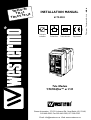
1
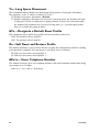
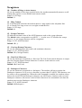
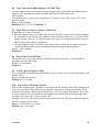
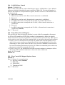
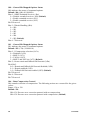
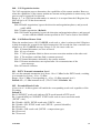
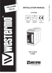
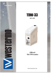
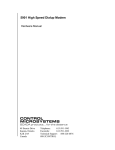
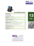
INSTALLATION MANUAL
6179-2203
Galvanic
Isolation
Transient
Protection
Balanced
Transmission
CE
Approved
© Westermo Teleindustri AB • 2001 • REV. A
V.90
TD33/ 3
TD-3 US
V.90
/
3
3
D
T
Tele Modem
V.90/K56flex™ or V.34
Gross Automation, 1725 S. Johnson Rd., New Berlin, WI, 53146,
262-446-0000, Fax 262-446-0300, 877-268-3700
Email: [email protected] Web: www.westermo.us
Table of Contents
Introduction
Safety
.....................................................................................................................................................................
3
..........................................................................................................................................................................................
3
Specifications
Installation
..................................................................................................................................................................
4
..........................................................................................................................................................................
5
RS-232/V.24 Connections
...........................................................................................................................
5
........................................................................................................................................
5
........................................................................................................................................................
6
LED Status Indicators
Line Connection
Typical TD-33 Line Connections
DIP Switch Setup
AT Commands
Result Codes
.....................................................................................................................................................
7
...............................................................................................................................................
8–20
21–23
.........................................................................................................................................................
24–31
................................................................................................................................................................
32–34
Applications
2
6
.................................................................................................................................................
S-Registers
Glossary
.....................................................................................................
.................................................................................................................................................................
35
6179-2203
Introduction
Congratulations for purchasing TD-33, probably the most robust modem device available on the market.
The TD-33 should not be confused with low-price replicas. You have just got a high quality product,
and with the excellent support from Westermo you will certainly not be unsatisfied with this product.
The Westermo TD-33 is an industrialised dial-up line modem. This modem has been developed to be
used in industrial applications and has some features one would not expect to find on a normal modem.
Terminal data rates of up to 115.2 kbit/s can be handled using data compression and error correction.
The maximum line modulation speed is 56.0 kbit/s (TD-33/V.90 ) or 33.6 kbit/s (TD-33 ).
A watchdog facility continually monitors the power supply and internal soft- and hardware. In the
event of a problem the modem automatically resets. This feature has been included to make the unit
more suitable for use in unmanned locations.
The TD-33 is available in two standard versions TD-33/V.90 including V.90 support and TD-33
containing up to V.34 support. The TD-33 is supplied by 12–36V DC.
The TD-33 has been designed with the engineer in mind, hence the extensive information on the
command set, S registers, DIP switches and error codes.
We have endeavoured to include all necessary information however if you need more please do not
hesitate to call us.
Safety
TD-33 and TD-33/V.90 comply with Directive 1999/5/EC.
The TD-33 shall only be connected to a power supply of type SELV.
Description of the above classifications are given in EN60950:1992
The TD-33 complies with EN-500081-1 & EN-500082-1
TD-33/V.90 US conforms to UL STD 1950 & CAN/CSA STD 22.2 No 950-95
Only Westermo TD-33/V90 US:
This equipment complies with Part 68 of the FCC Rules. On the outside of the package is a label that
contains, among other information, the FCC registration number for this equipment. If requested, provide this information to your telephone company. The registration jack for the equipment is RJ11C.
An FCC compliant telephone cord and modular plug is provided with this equipment. This equipment is designed to be connected to the telephone network or premises wiring using a compatible
modular jack which is Part 68 compliant. See installation instructions for details.
The Ringer Equivalent, REN is useful to determine the number of devices that may be connected
to the telephone line. Excessive RENs on the telephone line may result in the devices not ringing in
response to an incoming call. In most, but not all areas, the sum of RENs of all devices should not
exceed five (5). To be certain of the number of devices that may be connected to a line, as determined
by the total RENs, contact the local telephone company.
If your telephone equipment TD-33/V.90 US causes harm to the telephone network, the telephone
company will notify you in advance that temporary discontinuance of service may be required. But if
advance notice isn’t practical, you will be notified as soon as possible. You will be advised of your
right to file a complaint with the FCC if you believe it is necessary.
Your telephone company may make changes in its facilities, equipment, operations, or procedures
that could affect the operation of your equipment. If they do, you will be given advance notice so as
to give you an opportunity to maintain uninterrupted service. If you experience trouble with this
equipment TD-33/V.90 US please contact U.S. Repair Center: Gross Automation, 1725 S. Johnson Rd.
New Berlin, WI, 53146, 262-446-0000, 877-268-3700 for repair/warranty information. If your equipment is causing harm to the telephone network, the telephone company may request that you discount
the equipment until problem is resolved.
This equipment may not be used on public coin service provided by the telephone company.
Connection to party lines is subject to state tariffs. (Contact your state public utility commission or
corporation commission for information). Since the modem not provides adequate protection against
electric shock shall it not be positioned in operator access area.
The line cord for connection to outside of telephone line shall be of AWG26 or larger.
6179-2203
3
Specifications
Modulation
Dial up
Settings
Transmission
Transmission speed, DTE
Compression
Characters
Error correction
Interface
Line interface
Line
Power supply
Power consumption
Isolation
Fuse
Temperature
Humidity
Dimensions
Weight
Indications
Mounting
Misc.
4
ITU-T V.90 28.0 up to 56.0 kbit/s
K56flex™, 32.0 up to 56.0 kbit/s
ITU-T V.34, 2.4 up to 33.6 kbit/s
ITU-T V.32bis, 4.8 up to 14.4 kbit/s
ITU-T V.32, 4 800/9 600 bit/s
ITU-T v.23, 1 200 bit/s
ITU-T V.22bis, 2 400 bit/s
ITU-T V.22, Bell 212A, 1 200 bit/s
ITU-T V.21, Bell 103, 300 bit/s
Tone signals DTMF
AT-commands & switches
Asynchronous
300, 600, 1 200, 2 400, 4 800, 7 200, 9 600, 12.0k, 14.4k,
16.8k, 19.2k, 21.6k, 24.0k, 26.4k, 28.8k, 38.4k, 57.6k &
115.2kbit/s
V.42bis & MNP5
Up to 11 bits
V.42 LAPM, MNP 2-4 & MNP 10
EIA RS-232-C/V.24
RJ11
2-wire for dial up connections
12–36V DC
1.7 W at 12 V DC
Between line and rest of electronics 1500V
DC 1.0A
0 to 60°C surrounding temperature
0–95% RH, without condensation
55x100x128 mm (WxHxD)
0.2 kg
TD, RD, DCD, DTR, RTS and PWR
On 35 mm DIN-rail
Password/Callback, DTR Hotcall, DIP-switches
6179-2203
Installation
9
8
7
6
5
4
TD RD RTS
TD-33
9-pos
D-sub
▼
LED’s
DTR DCD PWR
3
2
1
DTR DCD PWR
▼
TD RD RTS
Computers or other equipment are connected through
RJ-11
an 9-pole D-sub RS-232/
Line
V.24 connection.
connection
Do not use ribbon cable
for RS-232 connections.
▼
The modem should be
connected in the following
way:
Power connection is made
through screw-block at
bottom right corner.
It is a 2-pole connector for
12–36 V DC supply.
TD-33
Only available in
TD-33/V90
V24/RS-232-C
TEL.LINE
▼
Power supply
Screw-block
RS-232/V.24 Connections
Pin outs for the 9-pole D-sub:
Direction
DCE-DTE
←
←
←
←
---
←
←
←
←
9-pos.
D-sub
1
2
3
4
5
6
7
8
9
Description
DCD/Data carrier detect
RXD/Receive data
TXD/Transmit data
DTR/Data terminal ready
SG/Signal ground
DSR/Data Set Ready
RTS/Request to send
CTS/Clear to send
RI/Ring indicator
TD-33/V.90, 9-pos screw terminal:
Screw
terminal
1
2
3
4
5
6
7
8
9
Description
SG/Signal Ground
DSR/Data Set Ready
DCD/Data Carrier Detect
DTR/Data Terminal Ready
CTS/Clear To Send
RTS/Request To Send
RXD/Receive Data
TXD/Transmit Data
SG/Signal Ground
LED Status Indicators
PWR
DTR
RTS
TD
RD
DCD
6179-2203
Power Indication. Flashes if an error is detected
Data Terminal Ready modem signal
Request To Send modem signal
Transmitted Data: Displays data received from the local RS-232/V.24 port
Received Data: Displays data leaving the modem on the RS-232/V.24 port
Data Carrier Detect modem signal
5
Line connection
The telephone line is connected to the 2-pole RJ-11 connector.
2-wire lines are connected to the two middle pins (3 & 4) in
the RJ-11 plug.
123456
Typical TD-33 line connections
RJ-11
plug
Telephone
Exchange
Telephone
Exchange
3
4
TEL.LINE
Dial up line 2-wire
6
6179-2203
DIP Switch Setup for Dial-up
Disconnect power before changing DIP-switches.
!
Use ESD-protection when changing switches.
ESD
TD RD RTS
The DIP-switches can be used to provide the following settings.
The DIP-Switches are underneath the top lid of the modem.
Non defined switches will be in off position.
DTR DCD PWR
TD-33
V24/RS-232-C
TEL.LINE
S1:1-4
Switch 1
ON
1 2 3 4
Use stored configuration (speed & format etc)
Disable DTR Hotcall
ON
Ignore DTE characters until DCD active.
1 2 3 4
ON
9 600 bit/s, 8N1
DTR Hotcall Enable
9 600 bit/s, 8E1
DTR Hotcall Enable
9 600 bit/s, 7E1
DTR Hotcall Enable
19 200 bit/s, 8N1
DTR Hotcall Enable
19 200 bit/s, 8E1
DTR Hotcall Enable
19 200 bit/s, 7E1
DTR Hotcall Enable
1 2 3 4
ON
1 2 3 4
ON
1 2 3 4
ON
1 2 3 4
ON
1 2 3 4
ON
1 2 3 4
Factory Settings
ON
1 2 3 4
6179-2203
Use stored configuration (speed & format etc)
Disable DTR Hotcall, Auto Baud
7
AT Commands
A – Answer
The modem will go off-hook and attempt to answer an incoming call if correct conditions
are met. Upon successful completion of answer handshake, the modem will go on-line in
answer mode.
The modem will enter the connect state after exchanging carrier with the remote modem.
If no carrier is detected within a period specified in register S7, the modem hangs up.
Any character entered during the connect sequence will abort the connection attempt.
Bn – ITU-T or Bell
When the modem is configured to allow either option, the modem will select Bell or
CCITT modulation for a line speed connection of 300 or 1200 bps according to the
parameter supplied. Any other line speed will use a CCITT modulation standard. The
parameter value, if valid, is written to S27 bit 6.
B0 Selects CCITT operation at 300 or 1200 bps during Call Establishment and a
subsequent connection. (Default)
B1 Selects BELL operation at 300 or 1200 bps during Call Establishment and a
subsequent connection.
\Bn – Transmit Break to Remote
In non-error correction mode, the modem will transmit a break signal to the remote
modem with a length in multiples of 100 ms according to parameter specified.
If a number in excess of 9 is entered, 9 is used. The command works in conjunction
with the \K command. In error correction mode, the modem will signal a break through
the active error correction protocol, giving no indication of the length.
\B1-\B9 Break length in 100 ms units. (Default = 3.) (Non-error corrected mode only.)
&Cn – RLSD (DCD) Option
The modem controls the RLSD output in accordance with the parameter supplied.
The parameter value, if valid, is written to S21 bit 5.
&C0 RLSD remains ON at all times.
&C1 RLSD follows the state of the carrier. (Default)
%C – Enable/Disable Data Compression
Enables or disables data compression negotiation. The modem can only perform data
compression on an error corrected link.
The parameter value, if valid, is written to S41 bits 0 and 1.
%C0 Disables data compression. Resets S46 bit 1.
%C1 Enables MNP 5 data compression negotiation. Resets S46 bit 1.
%C2 Enables V.42 bis data compression. Sets S46 bit 1.
%C3 Enables both V.42 bis and MNP 5 data compression. Sets S46 bit 1. (Default)
8
6179-2203
Dn – Dial
This command directs the modem to go on-line, dial according to the string entered and
attempt to establish a connection. If no dial string is supplied, the modem will go on-line
and attempt the handshake in originate mode.
NOTE:
If the ATD command is issued before the S1 register has cleared, the modem will respond
with the NO CARRIER result code.
The modem will behave as a data modem and will attempt to connect to another data
modem. The modem will have up to the period of time specified by register S6 to wait for
carrier and complete the handshake. If this time expires before the modem can complete
the handshake, the modem will go on-hook with the NO CARRIER response.This command will be aborted in progress upon receipt of any DTE character before completion of
the handshake.
Dial Modifiers
The valid dial string parameters are described below. Punctuation characters may be used
for clarity, with parentheses, hyphen, and spaces being ignored.
The valid dial string parameters are described below. Punctuation characters may be used
for clarity, with parentheses, hyphen, and spaces being ignored.
0-9
DTMF digits 0 to 9.
*
The ’star’ digit (tone dialing only).
#
The ’gate’ digit (tone dialing only).
A-D
DTMF digits A, B, C, and D. Some countries may prohibit sending of these
digits during dialing.
L
Re-dial last number: the modem will re-dial the last valid telephone number.
The L must be immediately after the D with all the following characters
ignored).
R
This command will be accepted, but not acted on.
S=n
Dial the number stored in the directory (n = 0 to 1). (See &Z.)
!
Flash: the modem will go on-hook for a time defined by the value of S29.
W
Wait for dial tone: the modem will wait for dial tone before dialing the digits
following ”W“. If dial tone is not detected within the time specified by S6
(EU), the modem will abort the rest of the sequence, return on-hook, and generate an error message.
@
Wait for silence: the modem will wait for at least 5 seconds of silence in the
call progress frequency band before continuing with the next dial string parameter. If the modem does not detect these 5 seconds of silence before the expiration of the call abort timer (S7), the modem will terminate the call attempt with
a NO ANSWER message. If busy detection is enabled, the modem may terminate the call with the BUSY result code. If answer tone arrives during execution of this parameter, the modem handshakes.
&
Wait for credit card dialing tone before continuing with the dial string. If the
tone is not detected within the time specified by S6 (EU models), the modem
will abort the rest of the sequence, return on-hook, and generate an error message.
6179-2203
9
,
Dial pause: the modem will pause for a time specified by S8 before dialing the
digits following ”,”.
;
Return to command state. Added to the end of a dial string, this causes the
modem to return to the command state after it processes the portion of the dial
string preceding the ”;”. This allows the user to issue additional AT commands
while remaining off-hook. The additional AT commands may be placed in the
original command line following the ”;” and/or may be entered on subsequent
command lines. The modem will enter call progress only after an additional
dial command is issued without the ”;” terminator. Use ”H” to abort the dial in
progress, and go back on-hook.
^
Toggles calling tone enable/disable: applicable to current dial attempt only.
()
Ignored: may be used to format the dial string.
Ignored: may be used to format the dial string.
<space> Ignored: may be used to format the dial string.
<i>
Invalid character: will be ignored.
&Dn – DTR Option
This command interprets the ON to OFF transition of the DTR signal from the DTE in
accordance with the parameter supplied. The parameter value, if valid, is written to S21
bits 3 and 4. Also, see S25.
&D0, DTR drop is interpreted according to the setting as follows: DTR is ignored
(assumed ON). Allows operation with DTEs which do not provide DTR.
(Default)
&D1 DTR drop is interpreted according to the setting as follows: DTR drop is interpreted by the modem as if the asynchronous escape sequence had been entered.
The modem returns to asynchronous command state without disconnecting.
&D2 DTR drop is interpreted according to the setting as follows: DTR drop causes the
modem to hang up. Auto-answer is inhibited.
&D3 DTR drop is interpreted according to the setting as follows: DTR drop causes the
modem to perform a soft reset as if the Z command were received. The &Y setting determines which profile is loaded.
En – Command Echo
The modem enables or disables the echo of characters to the DTE according to the parameter supplied. The parameter value, if valid, is written to S14 bit 1.
E0 Disables command echo.
E1 Enables command echo. (Default)
10
6179-2203
%En – Enable/Disable Line Quality Monitor and AutoRetrain or Fallback/Fall Forward
Controls whether or not the modem will automatically monitor the line quality and request
a retrain (%E1) or fall back when line quality is insufficient or fall forward when line quality is sufficient (%E2). The parameter value, if valid, is written to S41 bits 2 and 6.
If enabled, the modem attempts to retrain for a maximum of 30 seconds.
%E0 Disable line quality monitor and auto-retrain.
%E1 Enable line quality monitor and auto-retrain.
%E2 Enable line quality monitor and fallback/fall forward. (Default)
Fallback/Fall Forward. When %E2 is active, the modem monitors the line quality (EQM).
When line quality is insufficient, the modem will initiate a rate renegotiation to a lower
speed within the V.34/V.32 bis/V.32 (TD-33) modulation speeds. The modem will keep
falling back within the current modulation if necessary until the speed reaches 2 400 bit/s
(V.34) or 4 800 bit/s (V.32). Below this rate, the modem will only do retrains if EQM
thresholds are exceeded. If the EQM is sufficient for at least one minute, the modem will
initiate a rate renegotiation to a higher speed within the current modulation speeds. The
rate renegotiations will be done without a retrain if a V.32 bis connection is established.
Speeds attempted during fallback/fall forward are those shown to be available in the rate
sequences exchanged during the initial connection. Fallback/fall forward is available in
error correction and normal modes, but not in direct mode.
&Fn – Restore Factory Configuration (Profile)
The modem loads the factory default configuration (profile). The factory defaults are
identified for each command and in the S-Register descriptions. A configuration (profile)
consists of a subset of S-Registers.
&F0 Restore factory configuration 0.
&F1 Restore factory configuration 1.
&Gn – Select Guard Tone
The modem generates the guard tone selected by this command according to the parameter supplied (DPSK modulation modes only). The parameter value, if valid, is written to
S23 bits 6 and 7.
&G0 Disables guard tone. (Default).
&G1 Disables guard tone.
&G2 Selects 1 800 Hz guard tone.
This command may not be permitted in some countries.
*Gn – Password Enable/Disable
Controls whether or not the modem will handle Password and/or Callback functionality.
Value is written to S14 bit 6.
*G0 Disables Password handling. (Default).
*G1 Enable Password handling.
See also *Pn and *L.
6179-2203
11
Hn – Disconnect (Hang-Up)
This command initiates a hang up sequence.
H0 The modem will release the line if the modem is currently on-line. Country
specific, modulation specific, and error correction protocol specific (S38)
processing is handled outside of the H0 command.
H1 If on-hook, the modem will go off-hook and enter command mode.For EU models,
the modem will return on-hook after a period of time determined by S7.
\Kn – Break Control
Controls the response of the modem to a break received from the DTE or the remote
modem or the \B command according to the parameter supplied. The parameter value, if
valid, is written to S40 bits 3, 4, and 5.
The response is different in three separate states.
The first state is where the modem receives a break from the DTE when the modem is
operating in data transfer mode:
\K0 Enter on-line command mode, no break sent to the remote modem.
\K1 Clear data buffers and send break to remote modem.
\K2 Same as 0.
\K3 Send break to remote modem immediately.
\K4 Same as 0.
\K5 Send break to remote modem in sequence with transmitted data. (Default)
The second case is where the modem is in the on-line command state
(waiting for AT commands) during a data connection,
and the \B is received in order to send a break to the remote modem:
\K0 Clear data buffers and send break to remote modem.
\K1 Clear data buffers and send break to remote modem. (Same as 0.)
\K2 Send break to remote modem immediately.
\K3 Send break to remote modem immediately. (Same as 2.)
\K4 Send break to remote modem in sequence with data.
\K5 Send break to remote modem in sequence with data. (Same as 4.) (Default)
The third case is where a break is received from a remote modem during a non-error
corrected connection:
\K0 Clears data buffers and sends break to the DTE.
\K1 Clears data buffers and sends break to the DTE. (Same as 0.)
\K2 Send a break immediately to DTE.
\K3 Send a break immediately to DTE. (Same as 2.)
\K4 Send a break in sequence with received data to DTE.
\K5 Send a break in sequence with received data to DTE. (Same as 4.) (Default)
&K – Flow Control
Defines the DTE/DCE Flow Control. The parameter is written to S39 bits 0,1, and 2.
&K0 Disables flow control (Default).
&K3 Enables RTS/CTS.
&K4 Enables XON/XOFF.
&K5 Enables transparent XON/XOFF.
12
6179-2203
-Kn – MNP Extended Services
Enables or disables conversion of a V.42 LAPM connection to an MNP 10 connection.
The parameter value, if valid, is written to S40 bits 0 and 1.
-K0 Disables V.42 LAPM to MNP 10 conversion. (Default)
-K1 Enables V.42 LAPM to MNP 10 conversion.
-K2 Enables V.42 LAPM to MNP 10 conversion; inhibits MNP Extended Services initiation during V.42 LAPM answer mode detection phase.
%L – Report Line Signal Level
Returns a value which indicates the received signal level. The value returned is a direct
indication of the receive level at the MDP, not at the telephone line connector. For
example, 009 = –9 dBm, 043 = –43 dBm, and so on.
L – Speaker Volume
Sets the speaker volume control. The parameter is written to S22 bits 0 and 1.
L0 Low Volume
L1 Low Volume (Default)
L2 Medium Volume.
L3 High Volume.
*L – Display Stored Passwords and Callback numbers
This commands displays stored Password and Callback numbers.
M – Speaker Control
Speaker Control command. The parameter is written to S22 bits 2 and 3.
M0 Speaker is always off
M1 Speaker is on during call estabilishment, but off when receiving a carrier. (Default)
M2 Speaker is always on.
M3 Speaker is off when receiving a carrier and during dialing, but on during answering.
+MS – Select Modulation
This extended-format command selects the modulation and, optionally, enables or disables
automode, specifies the lowest and highest receive rates, and, specifies the highest transmit rate using one to six subparameters. The command format is:
+MS=<carrier>,<automode>,<min_tx_rate>,<max_tx_rate>,<min_rx_rate>,<max_rx_rate>
Where: <carrier> = A string which specifies the preferred modulation (automode enabled)
or the modulation (automode disabled) to use in originating or answering a connection.
The options are:
<carrier> Modulation Possible Rates (bit/s)
V21
V.21 300
V22
V.22 1 200
V22B V.22 bis 2 400 or 1 200
V23C V.23 1 200
V32
V.32 9 600 or 4 800
V32B V.32 bis 14 400, 12 000, 9 600, 7 200, or 4 800
V34
V.34 33 600, 31 200, 28 800, 26 400, 24 000, 21 600, 19 200, 16 800, 14 400,
12 000, 9 600, 7 200, 4 800, or 2 400
6179-2203
13
V90
B103
B212
V.90 56 000, 54 667, 53 333, 52 000, 50 667, 49 333, 48 000, 46 667, 45 333,
42 667, 41 333, 40 000, 38 667, 37 333, 36 000, 34 667, 33 333, 32 000, 30 667,
29 333, 28 000
Bell 103 300
Bell 212 1 200
<automode>
0 disable
1 enable
<min_xx_rate>, <max_xx_rate>
Min and max data rates depending on modulation used (see below).
Reporting Supported Options
The modem can send a string of information to the DTE consisting of supported options
using the following command:
+MS=?
or
For listing current configuration:
+MS?
\Nn – Operating Mode
This command controls the preferred error correcting mode to be negotiated in a
subsequent data connection.
\N0 Selects normal speed buffered mode (disables error-correction mode). (Forces &Q6.)
\N1 Serial interface selected – Selects direct mode and is equivalent to &Q0 mode of
operation. (Forces &Q0.)
\N2 Selects reliable (error-correction) mode. The modem will first attempt a LAPM
connection and then an MNP connection. Failure to make a reliable connection
results in the modem hanging up. (Forces &Q5, S36=4, and S48=7.)
\N3 Selects auto reliable mode. This operates the same as \N2 except failure to make a
reliable connection results in the modem falling back to the speed buffered normal
mode. (Forces &Q5, S36=7, and S48=7.)
\N4 Selects LAPM error-correction mode. Failure to make an LAPM error-correction
connection results in the modem hanging up. (Forces &Q5 and S48=0.) Note: The
-K1 command can override the \N4 command.
\N5 Selects MNP error-correction mode. Failure to make an MNP error-correction connection results in the modem hanging up. (Forces &Q5, S36=4, and S48=128.)
On – Return to On-Line Data Mode
This command determines how the modem will enter the on-line data mode. If the modem
is in the on-line command mode, it enters the on-line data mode with or without a retrain.
If the modem is in the off-line command mode (no connection), ERROR is reported.
O0 Enters on-line data mode without a retrain. Handling is determined by the Call
Establishment task.Generally, if a connection exists, this command connects the
DTE back to the remote modem after an escape (+++).
O1 Enters on-line data mode with a retrain before returning to on-line data mode.
14
6179-2203
*Pn – Store Password and Callback number
It is possible to store 2 different Passwords and Callback numbers in the modem.
This command works if command *G1 is used.
The command format is:
*P0:Password#0:Callbacknumber#0
*P1:Password#1:Callbacknumber#1
Password min. 6 characters max. 12 characters.
Callback number up to 18 characters.
If Password and Callback number is stored then the modem prompts the text ”PASSWORD:”
before releasing the connection and dialing back after a time given in S13.
If target is busy three retries will be executed.
If no Callback number is stored then the modem prompts the text ”PASSWORD:”
before switching into normal data transmission mode.
If no Password is stored then the modem prompts ”CALLBACK NUMBER:” before releasing
the connection and dialing back after a time given in S13.
Qn – Quiet Results Codes Control
The command enables or disables the sending of result codes to the DTE according to the
parameter supplied. The parameter value, if valid, is written to S14 bit 2.
Q0 Enables result codes to the DTE. (Default)
Q1 Disables result codes to the DTE.
&Q – Async Mode
This command is used to control the connection modes permitted. It is used in conjunction with S36 and S48. (Also, see \N).
&Q0 Selects direct asynchronous operation. The value 000b is written to S27 bits 3, 1,
and 0, respectively.
&Q5 The modem will try to negotiate an error-corrected link. The modem can be configured using S36 to determine whether a failure will result in the modem returning on hook or will result in fallback to an asynchronous connection. The value
101b is written to S27 bits 3, 1 and 0 respectively (Default).
&Q6 Selects asynchronous operation in normal mode (speed buffering). The value
110b is written to S27 bits 3, 1 and 0, respectively.
%Q – Report Line Signal Quality
Reports the line signal quality. Returns the higher order byte of the EQM value. Based on
the EQM value, retrain or fallback/fall forward may be initiated if enabled by %E1 or %E2.
&Sn – DSR Override
This command selects how the modem will control DSR. The parameter value, if valid, is
written to S21 bit 6.
&S0 DSR will remain ON at all times. (Default)
&S1 DSR will become active after answer tone has been detected and inactive after the
carrier has been lost.
6179-2203
15
%Un – Select µ-Law or A-Law Codec Type
This command selects µ-Law or A-Law codec type for V.90 and K56flex modulation.
This command also stores the selected setting directly to NVRAM.
%U0 Selects µ-Law.
%U1 Selects A-Law.
Vn – Result Code Form
This command selects the sending of short-form or long-form result codes to the DTE.
The parameter, if valid, is written to S14 bit 3.
V0 Enables short-form (terse) result codes. Line feed is not issued before a short-form
result code.
V1 Enables long-form (verbose) result codes. (Default)
\Vn – Single Line Connect Message Enable
This command enables or disables the single line connect message format as follows:
\V0 Connect messages are controlled by the command settings X, W, and S95.
\V1 Connect messages are displayed in the single line format described below subject
to the command settings V (Verbose) and Q (Quiet). In Non-Verbose mode (V0),
single line connect messages are disabled and a single numeric result code is generated for CONNECT DTE.
When single line connect messages are enabled, there are no CARRIER, PROTOCOL,
or COMPRESSION messages apart from the fields described below.
The single line connect message format is:
CONNECT <DTE Speed></Modulation></Protocol></Compression></Line
Speed>/<Voice and Data>
Where:
<DTE Speed> = DTE speed, e.g., 57 600.
Modulation = “V90” for V.90 modulation.
“K56” for K56flex modulation.
“V34” for V.34 modulation.
“V32” for V.32 or V.32bis modulation.
Note: Modulation is omitted for all other modulations.
Protocol = “NONE” for no protocol.
“ALT” for Microcom Network Protocol.
“LAPM” for LAP-M protocol.
Compression = “CLASS5” for Microcom MNP5 compression.
“V42BIS” for V.42bis compression.
Note: Compression is omitted if protocol is NONE.
Line Speed = Asymmetric rates are displayed as /rate:TX/rate:RX, e.g., /1 200
TX/75 RX.
Symmetric rates are displayed as a single DCE rate, e.g., 14 400.
Voice and Data = Blank for Data mode only.
LAPM-SREJ = Selective reject.
16
6179-2203
&V – Display Current Configuration and Stored Profiles
&V - Display Current Configuration and Stored Profiles Reports the current (active) configuration, the stored (user) profiles, and the first four stored telephone numbers. The
stored profiles and telephone numbers are not displayed if the NVRAM is not operational
as detected by the NVRAM test during reset processing.
Example:
AT&V
ACTIVE PROFILE:
B0 E1 L1 M1 N1 QO T V1 W0 X4 Y0 &C0 &D0 &G2 &K3 &Q5 &R1 &S0 &T4
&X0 &Y0 S00:002 S01:000 S02:043 S03:013 S04:010 S05:008 S06:002 S07:030
S08:002 S09:006 S10:014 S11:255 S12:050 S18:000 S25:005 S26:001 S36:007
S37:000 S38:020 S46:138 S48:007 S95:000
STORED PROFILE 0:
B0 E1 L1 M1 N1 QO T V1 W0 X4 Y0 &C0 &D0 &G2 &K3 &Q5 &R1 &S0 &T4
&X0 S00:002 S02:043 S06:002 S07:030 S08:002 S09:006 S10:014 S11:095 S12:050
S18:000 S36:007 S37:000 S40:105 S41:003 S46:138 S95:000
STORED PROFILE 1:
B0 E1 L1 M1 N1 QO T V1 W0 X4 Y0 &C0 &D0 &G2 &K3 &Q5 &R1 &S0 &T4
&X0 S00:002 S02:043 S06:002 S07:030 S08:002 S09:006 S10:014 S11:095 S12:050
S18:000 S36:007 S37:000 S40:105 S41:003 S46:138 S95:000
TELEPHONE NUMBERS:
0=1=
2=3=
OK
6179-2203
17
&V1 – Display Last Connection Statistics
Displays the last connection statistics in the following format (shown with typical results):
TERMINATION REASON.......... LOCAL REQUEST
LAST TX rate................ 26 400 BIT/S
HIGHEST TX rate............. 26 400 BIT/S
LAST RX rate................ 46 667 BIT/S
HIGHEST RX rate............. 46 667 BIT/S
PROTOCOL.................... LAPM
COMPRESSION................. V42Bis
Line QUALITY................ 033
Rx LEVEL.................... 015
Highest Rx State............ 67
Highest TX State............ 67
EQM Sum..................... 00C2
RBS Pattern................. FF
Rate Drop................... FF
Digital Pad................. None
Local Rtrn Count............ 00
Remote Rtrn Count........... 00
Flex 9481814347C4
RBS Pattern: Shows the number of least significant bits robbed per 6 bytes.
Digital Pad: Shows if a pad was encountered and if so, what was the digital loss.
Flex: Shows V.8bis information as follows:
First byte: Octect 13 (second byte of manufacturer id, 94 = K56flex)
Second byte: Octect 14 (Licensee code: 81 = Rockwell)
Third byte: Octect 15 (manufacturer's product capabilities)
Fourth byte: Octet 16 (K56flex version number)
Fifth byte: Octet 17 (Rockwell pump code version number)
Sixth byte: Octet 18 (x-law and controller version number)
Bit 6 Forced/Not forced A-Law/µ-Law
0 = Forced A-Law/µ-Law
1 = Not forced A-Law/µ-Law
Bit 5 Select A-Law or µ-Law
0 = Select A-Law
1 = Select µ-Law
Bit 4:0 Controller version
Wn – Connect Message Control
This command controls the format of CONNECT messages. The parameter value, if valid,
is written to S31 bits 2 and 3.
W0 Upon connection, the modem reports only the DTE speed (e.g., CONNECT
19 200). Subsequent responses are disabled.
W1 Upon connection, the modem reports the line speed, the error correction protocol,
and the DTE speed, respectively. Subsequent responses are disabled. (Default)
W2 Upon connection, the modem reports the DCE speed (e.g., CONNECT 14 400).
Subsequent responses are disabled.
18
6179-2203
&Wn – Store Current Configuration
Saves the current (active) configuration (profile), including S-Registers, in one of the two
user profiles in NVRAM as denoted by the parameter value. This command will yield an
ERROR message if the NVRAM is not operational as detected by the NVRAM test.
The current configuration is comprised of a list of storable parameters illustrated in the
&V command. These settings are restored to the active configuration upon receiving an
Zn command or at power up (see &Yn command).
&W0 Store the current configuration as profile 0.
&W1 Store the current configuration as profile 1.
Xn – Extended Result Codes
This command selects which subset of the result messages will be used by the modem to
inform the DTE of the results of commands.
Blind dialing is enabled or disabled by country parameters. If the user wishes to enforce
dial tone detection, a "W" can be placed in the dial string (see D command). Note that the
information below is based upon the default implementation of the X results table.
X0 Disables monitoring of busy tones unless forced otherwise by country requirements;
send only OK, CONNECT, RING, NO CARRIER, ERROR, and NO ANSWER
result codes. Blind dialing is enabled/disabled by country parameters. If busy tone
detection is enforced and busy tone is detected, NO CARRIER will be reported. If
dial tone detection is enforced or selected and dial tone is not detected, NO
CARRIER will be reported instead of NO DIAL TONE. The value 000b is
written to S22 bits 6, 5, and 4, respectively.
X1 Disables monitoring of busy tones unless forced otherwise by country requirements;
send only OK, CONNECT, RING, NO CARRIER, ERROR, NO ANSWER, and
CONNECT XXXX (XXXX = rate). Blind dialing enabled/disabled by country
parameters. If busy tone detection is enforced and busy tone is detected, NO
CARRIER will be reported instead of BUSY. If dial tone detection is enforced or
selected and dial tone is not detected, NO CARRIER will be reported instead of
NO DIAL TONE. The value 100b is written to S22 bits 6, 5, and 4, respectively.
X2 Disables monitoring of busy tones unless forced otherwise by country requirements;
send only OK, CONNECT, RING, NO CARRIER, ERROR, NO DIALTONE, NO
ANSWER, and CONNECT XXXX. If busy tone detection is enforced and busy
tone is detected, NO CARRIER will be reported instead of BUSY. If dial tone
detection is enforced or selected and dial tone is not detected, NO DIAL TONE will
be reported instead of NO CARRIER. The value 101b is written to S22 bits 6, 5,
and 4, respectively.
X3 Enables monitoring of busy tones; send only OK, CONNECT, RING, NO CARRIER, ERROR, NO ANSWER, and CONNECT XXXX. Blind dialing is enabled/disabled by country parameters. If dial tone detection is enforced and dial tone is not
detected, NO CARRIER will be reported. The value 110b is written to S22 bits 6,
5, and 4, respectively.
X4 Enables monitoring of busy tones; send all messages. The value 111b is written to
S22 bits 6, 5, and 4, respectively. (Default)
6179-2203
19
Yn – Long Space Disconnect
This command enables/disables the generation and response to long space disconnect.
The parameter value, if valid, is written to S21 bit 7.
Y0 Disables long space disconnect. (Default)
Y1 Enables long space disconnect. In non-error correction mode, the modem will send
a long space of four seconds prior to going on-hook. In non-error correction mode,
the modem will respond to the receipt of a long space (i.e., a break signal greater
than 1.6 seconds) by going on-hook.
&Yn – Designate a Default Reset Profile
This command selects which user profile will be used after a hard reset.
&Y0 The modem will use profile 0.
&Y1 The modem will use profile 1.
Zn – Soft Reset and Restore Profile
The modem performs a soft reset and restores (recalls) the configuration profile according
to the parameter supplied. If no parameter is specified, zero is assumed.
Z0 Soft reset and restore stored profile 0.
Z1 Soft reset and restore stored profile 1.
&Zn=x – Store Telephone Number
The modem can store up to two telephone numbers and each telephone number dial string
can contain up to 34 digits.
&Zn=x n = 0 to 1 and x = dial string.
20
6179-2203
Result Codes
0 OK A command line has been executed.
1 CONNECT For X command values specifying no speed reporting, the modem has connected to the line and
either the line speed is 300 bit/s and line speed is enabled, or the DTE speed is 300 bit/s and DTE speed reporting
is enabled.
2 RING An incoming ring signal is detected on the line.
3 NO CARRIER Sent when attempting to establish a call if:
1. Ringback is detected and later ceases but no carrier is detected within the period of time determined by register S7, or
2. No ringback is detected within the period of time determined by register S7.
Also sent when the modem auto-disconnects due to loss of carrier.
For X0, sent for the following conditions:
1. If busy tone detection is enforced, busy or circuit busy has been detected.
2. If dial tone detection is enforced or selected, dial tone has not been detected.
4 ERROR Sent during an attempt to execute a command line if any of the following conditions occur:
1. The command line contains a syntax error.
2. The modem cannot execute a command contained in the command line, i.e., the command does not
exist or is not supported.
3. A command parameter within the command line is outside the permitted range.
For X0, X1, X2, and X3, this message is sent instead of DELAYED and BLACKLISTED.
5 CONNECT 1 200 The modem has connected to the line and either the line speed is 1 200 bit/s and DCE speed
reporting is enabled, or the DTE speed is 1 200 bit/s and DTE speed reporting is enabled.
6 NO DIALTONE For X2 and X4, the modem has been instructed to wait for dial tone during dialing but none is
received.
7 BUSY For X3 and X4, if busy tone detection is enforced, the busy (engaged) signal is detected on the line when
the modem is attempting to originate a call.
8 NO ANSWER The modem is attempting to originate a call if a continuous ringback signal is detected on the line
until the expiration of the timer S7.
9 CONNECT 0600 The modem has connected to the line, the DTE speed is 600 bit/s, and DTE speed reporting is
enabled.
10 CONNECT 2 400 The modem has connected to the line and either the line speed is 2 400 bit/s and DCE speed
reporting is enabled, or the DTE speed is 2 400 bit/s and DTE speed reporting is enabled.
11 CONNECT 4 800 The modem has connected to the line and either the line speed is 4 800 bit/s and DCE speed
reporting is enabled, or the DTE speed is 4 800 bit/s and DTE speed reporting is enabled.
12 CONNECT 9 600 The modem has connected to the line and either the line speed is 9 600 bit/s and DCE speed
reporting is enabled, or the DTE speed is 9 600 bit/s and DTE speed reporting is enabled.
13 CONNECT 7 200 The modem has connected to the line at 7 200 bit/s and DCE speed reporting is enabled.
14 CONNECT 12 000 The modem has connected to the line at 12 000 bit/s and DCE speed reporting is enabled.
15 CONNECT 14 400 The modem has connected to the line at 14 400 bit/s and DCE speed reporting is enabled.
16 CONNECT 19 200 The modem has connected to the line and either the line speed is 19 200 bit/s and DCE
speed reporting is enabled, or the DTE speed is 19 200 bit/s and DTE speed reporting is enabled.
17 CONNECT 38 400 The modem has connected to the line, the DTE speed is
38 400 bit/s, and DTE speed reporting is enabled.
18 CONNECT 57 600 The modem has connected to the line, the DTE speed is 57 600 bit/s, and DTE speed reporting is enabled.
19 CONNECT 115 200 The modem has connected to the line, the DTE speed is 115 200 bit/s, and DTE speed
reporting is enabled.
22 CONNECT
75TX/1 200RX
The modem has established a V.23 originate connection and line speed reporting is enabled.
23 CONNECT
1 200TX/75RX
The modem has established a V.23 answer connection and line speed reporting is enabled.
24 DELAYED For X4, sent when a call fails to connect and the number dialed is considered ’delayed’ due to
country blacklisting requirements.
32 BLACKLISTED For X4, sent when a call fails to connect and the number dialed is considered ’blacklisted’.
40 CARRIER 300 The modem has connected to the line at 0–300 bit/s and carrier reporting is enabled.
(See S95 and Xn.)
44 CARRIER 1 200/75 The V.23 backward channel carrier is detected and carrier reporting is enabled.
(See S95 and Xn.)
45 CARRIER 75/1 200 The V.23 forward channel carrier is detected and carrier reporting is enabled.
(See S95 and Xn.)
46 CARRIER 1 200 The modem has connected to the line at 1200 bit/s and carrier reporting is enabled.
(See S95 and Xn.)
47 CARRIER 2 400 The modem has connected to the line at 2400 bit/s and carrier reporting is enabled.
(See S95 and Xn.)
6179-2203
21
48 CARRIER 4 800 The modem has connected to the line at 4 800 bit/s and carrier reporting is enabled.
(See S95 and Xn.)
49 CARRIER 7 200 The modem has connected to the line at 7 200 bit/s and carrier reporting is enabled.
(See S95 and Xn.)
50 CARRIER 9 600 The modem has connected to the line at 9 600 bit/s and carrier reporting is enabled.
(See S95 and Xn.)
51 CARRIER 12 000 The modem has connected to the line at 12 000 bit/s and carrier reporting is enabled.
(See S95 and Xn.)
52 CARRIER 14 400 The modem has connected to the line at 14 400 bit/s and carrier reporting is enabled.
(See S95 and Xn.)
53 CARRIER 16 800 The modem has connected to the line at 16 800 bit/s and carrier reporting is enabled.
(See S95 and Xn.)
54 CARRIER 19 200 The modem has connected to the line at 19 200 bit/s and carrier reporting is enabled.
(See S95 and Xn.)
55 CARRIER 21 600 The modem has connected to the line at 21 600 bit/s and carrier reporting is enabled.
(See S95 and Xn.)
56 CARRIER 24 000 The modem has connected to the line at 24 000 bit/s and carrier reporting is enabled.
(See S95 and Xn.)
57 CARRIER 26 400 The modem has connected to the line at 26 400 bit/s and carrier reporting is enabled.
(See S95 and Xn.)
58 CARRIER 28 800 The modem has connected to the line at 28 800 bit/s and carrier reporting is enabled.
(See S95 and Xn.)
59 CONNECT 16 800 The modem has connected to the line, the DTE speed is 16 800 bit/s and DTE speed
reporting is enabled.
61 CONNECT 21 600 The modem has connected to the line, the DTE speed is 21 600 bit/s and DTE speed
reporting is enabled.
62 CONNECT 24 000 The modem has connected to the line, the DTE speed is 24 000 bit/s and DTE speed
reporting is enabled.
63 CONNECT 26 400 The modem has connected to the line, the DTE speed is 26 400 bit/s and DTE speed
reporting is enabled.
64 CONNECT 28 800 The modem has connected to the line and either the line speed is 28 800 bit/s and DCE
speed reporting is enabled, or the DTE speed is 28 800 bit/s and DTE speed reporting is enabled.
66 COMPRESSION:
CLASS 5
The modem has connected to the line in MNP Class 5 and COMPRESSION message reporting is enabled.
(See S95, Wn, and Xn.)
67 COMPRESSION:
V.42 bis
The modem has connected to the line in V.42 bis and COMPRESSION message reporting is enabled.
(See S95, Wn, and Xn.)
69 COMPRESSION:
NONE
The modem has connected to the line without data compression and COMPRESSION message reporting is
enabled. (See S95, Wn, and Xn.)
70 PROTOCOL: NONE The modem has connected to the line without any form of error correction and the
PROTOCOL message reporting has been enabled.
(See S95, Wn, and Xn.)
77 PROTOCOL: LAPM The modem has connected to the line in V.42 LAPM error correction mode and
PROTOCOL message reporting has been enabled.
(See S95, Wn, and Xn.)
78 CARRIER 31 200 The modem has connected to the line at 31 200 bit/s and carrier reporting is enabled.
(See S95 and Xn.)
79 CARRIER 33 600 The modem has connected to the line at 33 600 bit/s and carrier reporting is enabled.
(See S95 and Xn.)
80 PROTOCOL: ALT Sent when the modem has connected in the MNP mode of error correction, and PROTOCOL
message reporting has been enabled.
(See S95, Wn, and Xn.)
84 CONNECT 33 600 The modem has connected to the line, the DTE speed is 33 600 bit/s and the DTE speed
reporting is enabled.
91 CONNECT 31 200 The modem has connected to the line DTE speed is 31 200 bit/s and the modem is to report
the DTE speed upon connecting.
150 CARRIER 32 000 The modem has connected to the line at 32 000 bit/s and carrier reporting is enabled.
(See S95 and Xn.)
151 CARRIER 34 000 The modem has connected to the line at 34 000 bit/s and carrier reporting is enabled.
(See S95 and Xn.)
152 CARRIER 36 000 The modem has connected to the line at 36 000 bit/s and carrier reporting is enabled.
(See S95 and Xn.)
22
6179-2203
153 CARRIER 38 000 The modem has connected to the line at 38 000 bit/s and carrier reporting is enabled.
(See S95 and Xn.)
154 CARRIER 40 000 The modem has connected to the line at 40 000 bit/s and carrier reporting is enabled.
(See S95 and Xn.)
155 CARRIER 42 000 The modem has connected to the line at 42 000 bit/s and carrier reporting is enabled.
(See S95 and Xn.)
156 CARRIER 44 000 The modem has connected to the line at 44 000 bit/s and carrier reporting is enabled.
(See S95 and Xn.)
157 CARRIER 46 000 The modem has connected to the line at 46 000 bit/s and carrier reporting is enabled.
(See S95 and Xn.)
158 CARRIER 48 000 The modem has connected to the line at 48 000 bit/s and carrier reporting is enabled.
(See S95 and Xn.)
159 CARRIER 50 000 The modem has connected to the line at 50 000 bit/s and carrier reporting is enabled.
(See S95 and Xn.)
160 CARRIER 52 000 The modem has connected to the line at 52 000 bit/s and carrier reporting is enabled.
(See S95 and Xn.)
161 CARRIER 54 000 The modem has connected to the line at 54 000 bit/s and carrier reporting is enabled.
(See S95 and Xn.)
162 CARRIER 56 000 The modem has connected to the line at 56 000 bit/s and carrier reporting is enabled.
(See S95 and Xn.)
165 CONNECT 32 000 The modem has connected to the line at 32 000 bit/s and DCE speed reporting is enabled.
166 CONNECT 34 000 The modem has connected to the line at 34 000 bit/s and DCE speed reporting is enabled.
167 CONNECT 36 000 The modem has connected to the line at 36 000 bit/s and DCE speed reporting is enabled.
168 CONNECT 38 000 The modem has connected to the line at 38 000 bit/s and DCE speed reporting is enabled.
169 CONNECT 40 000 The modem has connected to the line at 40 000 bit/s and DCE speed reporting is enabled.
170 CONNECT 42 000 The modem has connected to the line at 42 000 bit/s and DCE speed reporting is enabled.
171 CONNECT 44 000 The modem has connected to the line at 44 000 bit/s and DCE speed reporting is enabled.
172 CONNECT 46 000 The modem has connected to the line at 46 000 bit/s and DCE speed reporting is enabled.
173 CONNECT 48 000 The modem has connected to the line at 48 000 bit/s and DCE speed reporting is enabled.
174 CONNECT 50 000 The modem has connected to the line at 50 000 bit/s and DCE speed reporting is enabled.
175 CONNECT 52 000 The modem has connected to the line at 52 000 bit/s and DCE speed reporting is enabled.
176 CONNECT 54 000 The modem has connected to the line at 54 000 bit/s and DCE speed reporting is enabled.
177 CONNECT 56 000 The modem has connected to the line at 56 000 bit/s and DCE speed reporting is enabled.
178 CONNECT 230 400 The modem has connected to the line, the DTE speed is 230 400 bit/s, and DTE speed
reporting is enabled.
180 CONNECT 28 000 The modem has connected to the line at 28 000 bit/s and DCE reporting is enabled.
181 CONNECT 29 333 The modem has connected to the line at 29 333 bit/s and DCE reporting is enabled.
182 CONNECT 30 667 The modem has connected to the line at 30 667 bit/s and DCE reporting is enabled.
183 CONNECT 33 333 The modem has connected to the line at 33 333 bit/s and DCE reporting is enabled.
184 CONNECT 34 667 The modem has connected to the line at 34 667 bit/s and DCE reporting is enabled.
185 CONNECT 37 333 The modem has connected to the line at 37 333 bit/s and DCE reporting is enabled.
186 CONNECT 38 667 The modem has connected to the line at 38 667 bit/s and DCE reporting is enabled.
187 CONNECT 41 333 The modem has connected to the line at 41 333 bit/s and DCE reporting is enabled.
188 CONNECT 42 667 The modem has connected to the line at 42 667 bit/s and DCE reporting is enabled.
189 CONNECT 45 333 The modem has connected to the line at 45 333 bit/s and DCE reporting is enabled.
190 CONNECT 46 667 The modem has connected to the line at 46 667 bit/s and DCE reporting is enabled.
191 CONNECT 49 333 The modem has connected to the line at 49 333 bit/s and DCE reporting is enabled.
192 CONNECT 50 667 The modem has connected to the line at 50 667 bit/s and DCE reporting is enabled.
193 CONNECT 53 333 The modem has connected to the line at 53 333 bit/s and DCE reporting is enabled.
194 CONNECT 54 667 The modem has connected to the line at 54 667 bit/s and DCE reporting is enabled.
6179-2203
23
S-registers
S0 – Number of Rings to Auto-Answer
S0 sets the number of the rings required before the modem automatically answers a call.
Setting this register to zero disables auto-answer mode.
Range: 0–255 rings
Default: 2
S1 – Ring Counter
S1 is incremented each time the modem detects a ring signal on the telephone line.
S1 is cleared if no rings occur over an eight second interval.
Range: 0–255 rings
Default: 0
S2 – Escape Character
S2 holds the decimal value of the ASCII character used as the escape character.
The default value corresponds to an ASCII ’+’. A value over 127 disables the escape
process, i.e., no escape character will be recognized.
Range: 0–255, ASCII decimal
Default: 43 (+)
S3 – Carriage Return Character
S3 sets the command line and result code terminator character.
Range: 0–127, ASCII decimal
Default: 13 (Carriage Return)
S4 – Line Feed Character
S4 sets the character recognized as a line feed. The Line Feed control character is output
after the Carriage Return control character if verbose result codes are used.
Range: 0–127, ASCII decimal
Default: 10 (Line Feed)
S5 – Backspace Character
S5 sets the character recognized as a backspace. The modem will not recognize the
Backspace character if it is set to a value that is greater than 32 ASCII. This character can
be used to edit a command line. When the echo command is enabled, the modem echoes
back to the local DTE the Backspace character, an ASCII space character and a second
Backspace character; this means a total of three characters are transmitted each time the
modem processes the Backspace character.
Range: 0–32, ASCII decimal
Default: 8 (Backspace)
24
6179-2203
S6 – Wait Time before Blind Dialing or for Dial Tone
Sets the length of time, in seconds, that the modem will wait for dial tone when encountering a “W” dial modifier before returning NO DIAL TONE result code.
(EU models)
The modem always pauses for a minimum of 2 seconds, even if the value of S6 is less
than 2 seconds.
Range: 2–60 seconds
Default: 4 (TD-33/V.90 US Default: 2)
S7 – Wait Time for Carrier, Silence, or Dial Tone
S7operation is country dependent.
1. Sets the length of time, in seconds, that the modem will wait for carrier before hanging
up. The timer is started when the modem finishes dialing (originate), or 2 seconds after
going off-hook (answer). In originate mode, the timer is reset upon detection of answer
tone if allowed by country restrictions.
2. Sets the length of time, in seconds, that modem will wait for silence when encountering the @ dial modifier before continuing with the next dial string parameter.
Range: 1–255 seconds
Default: 50
S8 – Pause Time For Dial Delay
S8 sets the time, in seconds, that the modem must pause when the “,” dial modifier is
encountered in the dial string.
Range: 0–255 seconds
Default: 2
S9 – Carrier Detect Response Time
S9 is supported for backwards compatibility only. No value can be written. Responds with
default value.
Range: 6 tenths of a second
Default: 6 (0.6 second)
S10 – Lost Carrier To Hang Up Delay
S10 sets the length of time, in tenths of a second, that the modem waits before hanging up
after a loss of carrier. This allows for a temporary carrier loss without causing the local
modem to disconnect. When register S10 is set to 255, the modem functions as if a carrier
is always present. The actual interval the modem waits before disconnecting is the value
in register S10 minus the value in register S9.
Therefore, the S10 value must be greater than the S9 value or else the modem disconnects
before it recognizes the carrier.
Range: 1–255 tenths of a second
Default: 14 (1.4 seconds)
6179-2203
25
S11 – DTMF Tone Duration
S11 operation is country dependent.
Range: 50–255 milliseconds
Default: 95 (95 milliseconds)
S12 – Escape Prompt Delay (EPD)
S12 defines the maximum period, in fiftieths of a second, allowed between receipt of the
last character of the three escape character sequence from the DTE and sending of the OK
result code to the DTE. If any characters are detected during this time, the OK will not be
sent. Note that sending of the OK result code does not affect entry into command mode.
Range: 0–255 1/50 of a second
Default: 50 (1 second)
S13 – Callback delay time
S13 defines the time between that the modem releses connection and dials a stored callback number.
Range: 0–255 seconds
Default: 10 (10 seconds)
S14 – General Bit Mapped Options Status
S14 indicates the status of command options.
Default: 138 (8Ah) (10001010b)
Bit 0 This bit is ignored.
Bit 1 Command echo (En)
0 = Disabled (E0)
1 = Enabled (E1) (Default)
Bit 2 Quiet mode (Qn)
0 = Send result codes (Q0) (Default)
1 = Do not send result codes (Q1)
Bit 3 Result codes (Vn)
0 = Numeric (V0)
1 = Verbose (V1) (Default)
Bit 4 Reserved
Bit 5 Tone (T)
0 = Tone (T) (Default)
Bit 6 Password (*Gn)
0 = Disabled (*G0) (Default)
1 = Enabled (*G1)
Bit 7 Originate/Answer
0 = Answer
1 = Originate (Default)
26
6179-2203
S21 – V.24/General Bit Mapped Options Status
S21 indicates the status of command options.
Default: 36 (24h) (00100100b)
Bit 0 Reserved (0)
Bit 1 Reserved (0)
Bit 2 CTS behavior (&Rn)
0 = CTS tracks RTS (&R0)
1 = CTS always on (&R1) (Default)
Bits 3–4 DTR behavior (&Dn)
0 = &D0 selected (Default)
1 = &D1 selected
2 = &D2 selected
3 = &D3 selected
Bit 5 RLSD (DCD) behavior (&Cn)
0 = &C0 selected
1 = &C1 selected (Default)
Bit 6 DSR behavior (&Sn)
0 = &S0 selected (Default)
1 = &S1 selected
Bit 7 Long space disconnect (Yn)
0 = Y0 (Default)
1 = Y1
S22 Speaker/Results Bit Mapped Options Status
S22 indicates the status of commands options.
Default: 117 (75h) (01110101b)
Bits 0–1 Speaker volume (Ln)
0 = Off(L0)
1 = Low(L1) (Default)
2 = Medium(L2)
3=High(L3)
Bits 2–3 Speaker Control (Mn)
0 = Disabled (M0)
1 = Off on carrier (M1) (Default)
2 = Always on (M2)
3= On during handshake
Bits 4-6 Limit result codes (Xn)
0 = X0
4 = X1
5 = X2
6 = X3
7 = X4 (Default)
Bit7
Reserved
6179-2203
27
S25 – Delay To DTR
S25 sets the length of time that the modem will ignore DTR for taking the action specified
by &Dn. Its units are one hundredths of a second for other modes.
Range: 0–255 (0.01 seconds)
Default: 5 (0.05 seconds)
S29 – Flash Dial Modifier Time
S29 sets the length of time, in units of 10 ms, that the modem will go on-hook when it
encounters the flash (!) dial modifier in the dial string. The time can be limited as it is a
country dependent parameter.
Range: 0–255 10 ms intervals
Default: 0 (0 ms) (TD-33/V.90 US Fixed: 70)
S30 – Disconnect Inactivity Timer
S30 sets the length of time, in tens of seconds, that the modem will stay online before disconnecting when no data is sent or received. In error-correction mode, any data transmitted
or received will reset the timer. In other modes, any data transmitted will reset the timer.
Range: 0–255 tens of seconds (0–2 550 seconds)
Default: 0 (disabled)
S31 – Bit Mapped Options Status
S31 indicates bit mapped options status.
Bit 0 Single line connect message enable/disable (\Vn)
0 = Messages controlled by S95, Wn and Vn (\V0) (Default)
1 = Single line connect message (\V1)
Bit 1 Auto line speed detection (Nn)
0 = Disabled (N0)
1 = Enabled (N1) (Default)
Bits 2–3 Error correction progress messages (Wn)
0 = DTE speed only (W0)
1 = Full reporting (W1) (Default)
2 = DCE (line) speed only (W2)
Bits 4–5 Not used
0 = (Default)
Bits 6–7 Reserved (Default = 11b)
28
6179-2203
S36 – LAPM Failure Control
Default: 7 (00000111b)
Bits 0–2 This value indicates what should happen upon a LAPM failure. These fallback
options are initiated immediately upon connection if S48=128. If an invalid number is
entered, the number is accepted into the register, but S36 will act as if the default value
has been entered.
0 = Modem disconnects.
1 = Modem stays on-line and a Direct mode connection is established.
2 = Reserved.
3 = Modem stays on-line and a Normal mode connection is established.
4 = An MNP connection is attempted and if it fails, the modem disconnects.
5 = An MNP connection is attempted and if it fails, a Direct mode connection is
established.
6 = Reserved.
7 = An MNP connection is attempted and if it fails, a Normal mode connection is
established. (Default)
Bits 3–7 Reserved
S38 – Delay Before Forced Hang Up
S38 specifies the delay between the modem’s receipt of the H command to disconnect
(or ON-to-OFF transition of DTR if the modem is programmed to follow the signal),
and the disconnect operation. Applicable to error-correction connection only. This register
can be used to ensure that data in the modem buffer is sent before the modem disconnects.
1. If S38 is set to a value between 0 and 254, the modem will wait that number of seconds for the remote modem to acknowledge all data in the modem buffer before disconnecting. If time expires before all data is sent, the NO CARRIER result code will
be issued to indicate that data has been lost. If all data is transmitted prior to time-out,
the response to the H0 command will be OK.
2. If S38 is set to 255, the modem does not time-out and continues to attempt to deliver
data in the buffer until the connection is lost or the data is delivered.
Range: 0–255 seconds
Default: 20
S39 – Flow Control Bit Mapped Options Status
Default: 0
Bits 0–2 Status of command options
0 = No flow control (Default)
3 = RTS/CTS
4 = XON/XOFF
5 = Transparent XON
Bits 3–7 Reserved
6179-2203
29
S40 – General Bit Mapped Options Status
S40 indicates the status of command options.
Default: 104 (68h) (01101000b)
Bits 0–1 MNP Extended Services (-Kn)
0 = Disable extended services (-K0) (Default)
1 = Enable extended services (-K1)
2 = Enable extended services (-K2)
Bit 2 Reserved
Bits 3–5 Break Handling (\Kn)
0 = \K0
1 = \K1
2 = \K2
3 = \K3
4 = \K4
5 = \K5 (Default)
Bits 6–7 Reserved
S41 – General Bit Mapped Options Status
S41 indicates the status of command options.
Default: 195 (C3h) (11000011b)
Bits 0–1 Compression selection (%Cn)
0 = Disabled (%C0)
1 = MNP 5 (%C1)
2 = V.42 bis (%C2)
3 = MNP 5 and V.42 bis (%C3) (Default)
Bits 2, 6 Auto retrain and fallback/fall forward (%En)
Bit 6 Bit 2
0 0 = Retrain and fallback/fall forward disabled (%E0)
0 1 = Retrain enabled (%E1)
1 0 = Fallback/fall forward enabled (%E2) (Default)
Bit 3 Reserved
Bits 4–5 Reserved
Bit 7 Reserved
S46 – Data Compression Control
S46 controls selection of compression. The following actions are executed for the given
values:
Range: 136 or 138
Default: 138
S46=136 Execute error correction protocol with no compression.
S46=138 Execute error correction protocol with compression. (Default)
30
6179-2203
S48 – V.42 Negotiation Action
The V.42 negotiation process determines the capabilities of the remote modem. However,
when the capabilities of the remote modem are known and negotiation is unnecessary, this
process can be bypassed if so desired.
Range: 0, 7, or 128 If an invalid number is entered, it is accepted into the S-Register, but
S48 will act as if 128 has been entered.
Default: 7
S48=0 Disable negotiation; bypass the detection and negotiation phases; and proceed
with LAPM.
S48=7 Enable negotiation. (Default)
S48=128 Disable negotiation; bypass the detection and negotiation phases; and proceed
at once with the fallback action specified in S36. Can be used to force MNP.
S86 – Call Failure Reason Code
When the modem issues a NO CARRIER result code, a value is written to this S-Register
to help determine the reason for the failed connection. S86 records the first event that contributes to a NO CARRIER message. Range: 0–24, the cause codes are:
S86= 0 Normal disconnect, no error occurred.
S86= 4 Loss of carrier.
S86= 5 V.42 negotiation failed to detect an error-correction modem at the other end.
S86= 9 The modems could not find a common protocol.
S86=12 Normal disconnect initiated by the remote modem.
S86=13 Remote modem does not respond after 10 re-transmissions of the
same message.
S86=14 Protocol violation.
S91 – PSTN Transmit Attenuation Level
S91 sets the transmit attenuation level from –10 to 15 dBm for the PSTN mode, resulting
in a transmit level from –10 to –15 dBm.
Range: 10 to 15 dBm (Corresponding to –10 to –15 dBm transmit level.)
Default: 13 (–13 dBm transmit level). (TD-33/V.90 US Default: 10)
S95 – Extended Result Codes
A bit set to a 1 in this register will enable the corresponding result code regardless of the
W setting.
Default: 0
Bit 0 CONNECT result code indicates DCE speed instead of DTE speed.
Bit 1 Append/ARQ to CONNECT XXXX result code in error-correction mode
(XXXX = rate).
Bit 2 Enable +MCR: XXXX result code (XXXX = rate).
Bit 3 Enable +ER: XXXX result code (XXXX = protocol identifier).
Bit 4 Reserved.
Bit 5 Enable +DR: result code (XXXX = compression type).
Bit 6 Reserved.
Bit 7 Reserved.
6179-2203
31
Glossary
ASCII
A binary code system which defines 128 characters using different combinations of 1s and 0s. ASCII
= American Standard Code for Information Interchange.
Asynchronous Data
Transmission where the characters are transmitted one at a time, starting with a start bit and ending
with a stop bit. About 90–95% of all serial data communications are asynchronous.
Baud
The number of data symbols transmitted every second. Often baud = bit/s. Sometimes a few data symbols can represent several bits since different coding are used to compress data.
Buffer
A memory for storing data for a short time, e.g. until the receiver is ready.
Byte
A byte is a number of data bits (1s or 0s) which forms a character. Most often a character consists of
7 or 8 bits.
DCE
Describes which direction the signals in the RS-232/V.24 contact have. Modems are often DCE.
DCE = Data Communication Equipment.
DIN rail
An installation rail which is used in apparatus cubicles to set up different equipment on a simple way.
DIN = Deutsche Industri Norme.
DTE
Same as DCE but the signals are directed on opposite directions. Terminals, PC’s and printers are
most often DTE. DTE = Data Terminal Equipment.
Data Compression and Error Correction.
V.42
ITU-T’s error correction protocol incorporating LAPM. If the V.42 connection fails
then usually MNP will be tried.
LAPM
Link Access Procedure for Modems. An error correction method used in transmissions via PTT modems.
MNP
Microcom Networking Protocol. Several methods for error correction and data compression for PTT modems.
MNP 1: Asynchronous Protocol, half duplex.
MNP 2: Asynchronous Protocol, full duplex, Data is divided into blocks
(slower data rate).
MNP 3: Synchronous Protocol, full duplex. Data in blocks
(higher speeds with no errors).
MNP 4: Similar to 3, but with smaller data blocks allowing for faster data rates
with no errors.
MNP 5: Level 4 with data compression, gives about double the data rate.
MNP 10: Development of MNP5 with dynamic line monitoring and block size
adjustment, used on very bad lines (cellular phone connections).
ARQ
Automatic Repeat reQuest. When incorrect data is detected a request to retransmit
the data is made to the remote modem.
V.42bis.
Data Compression technique used by modems rather than MNP5, because it offers
better transmission on already compressed data.
32
6179-2203
Data Rate
In modems this is often different to the baud rate. For instance the Data Rate of V.32bis is 14 400bit/s
and the baud rate is 2 400 symbols/second.
Direct Mode
The Data to be transmitted is sent directly to the data pump (the modem circuit). No compression,
error correction or buffering occurs, allowing the data to be transmitted across the link unaltered by
the modem.
Duplex
Means that the communication is bi-directional. In half duplex, the devices take turns sending and
receiving. In full duplex, sending and receiving can take place simultaneously.
Hayes commands
A set of commands for controlling PTT modems. Often referred to as the AT command set, since all
commands are started with AT. Most modems support these commands, but there are variations and
commands that are specific for a certain modem.
ISP
Internet Service Provider.
LED
Light-Emitting Diode. A semi-conductor which emits light when it receives an electrical current.
In modems they are used as indicators for data and status signals.
Modem
Acronym of the words modulator and demodulator. Modulates or transforms the signal from
computer equipment into electrical or acoustic signals for transmission. The receiver has a
similar modem which retransforms the signal, demodulation.
Modem Modulation Standards
V.21
300 bit/s, similar to Bell 103
V.23
1 200/75 bit/s Split speed line
V.22
1 200 bit/s full duplex.
V.22bis
2 400 bit/s full duplex.
V.32
9 600 bit/s full duplex.
V.32bis
14 400 bit/s full duplex.
V.34
33 600 bit/s full duplex.
V.90/K56flex
Asymmetrical transmission standards 56kbit/s downstream data, 33.6kbit/s
upstream data.
Modulation Techniques
DPSK
Differential Phase Shift Keying. Employed in data rates up to 4 800 bit/s.
FSK
Frequency Shift Keying. Used in the lowest data rate standards.
QAM
Quadrature Amplitude Modulation. A technique used for data rates up to 9 600 bit/s.
TCM
Trellis Coded Modulation. Used in the high speed modulations.
PCM
Pulse Coded Modulation. Used in the V.90 standard for downstreaming data from a digital end.
6179-2203
33
NVRAM
Non Volatile Random Access Memory. Consists most often by an EEPROM (Electronically Eraseable
and Programmable memory). Used by the modem to store profile information and numbers even
when the unit has no power.
Normal Mode
A non error corrected connection, where data is buffered.
Off Hook
Like picking up the receiver. Connecting to a line.
On Hook
Like hanging up the receiver. Disconnecting.
PSTN
Public Switched Telephone Network, i.e. a normal telephone line on which other subscribers can be
called.
Parity
A mathematically derived bit which is added by the transmitter. The receiver checks it to detect any
error in transmission. Occurring parities are even, odd and none.
REN Number
The Ringer Equivalence Number (REN) is a way of measuring the load on the telephone line caused
by the connected equipment.
RS-232/V.24 Signals
TD
Transmitted Data. Data going from DTE to DCE.
RD
Received Data. The Data going from DCE to DTE.
RTS
Request To Send from DTE.
DSR
Data Set Ready. The DCE-equipment is powered and usable.
DTR
Data Terminal Ready. The DTE-equipment is powered and usable.
DCD
Data Carrier Detect. A signal from the DCE indicating that a carrier is present on the line.
Simplex
Uni-directional communication.
Start bit
Marks the start of a character at asynchronous communication.
Stop bit
One or more stop bits marks the end of a character at asynchronous communication. Systems that
require more than one stop bit may have problems during communication via modems, since modems
most often remove the second stop bit.
34
6179-2203
Dial up with hardware signalling “DTR-Hotcall”
DSR
DTR
Dial up can be made by applying an external signal to the DTR-pin in the RS-232/V.24 contact.
A typical application is an alarm signal from a PLC or another relay contact (as shown in figure).
The modem reacts on the first rising edge which means that one pulse is sufficient if it remains active
during the connection.
The signal level should be in compliance with the RS-232/V.24 standard. If only a relay contact
is available the DSR-pin will provide a suitable voltage.
AT&S0
SW1:1, 2, 3
AT&D2
AT&Z0=nn
DTR pin active
DSR-pin ON.
DTE Speed and Format setting.
Hang-up if DTR goes low.
The number to dial, nn, is stored in memory position 0.
(sets the connection).
Remark: SW1:4 ON (Ignore DTE Characters) may be combined with the settings above to avoid an
abort during call estabilishment.
A frequently used setting for PLC-systems
and industrial applications
Most PLC-systems and other industrial applications where modems are used require the same
changes to the standard settings.
The most commonly encountered problems concern speed, parity and control signals from the
connected equipment.
6 common settings are providing with SW1: 1, 2, 3.
The PLC Mode settings are as follows:
SW1: 4
AT&C1
AT&K0
Commands that are sent from the terminal/computer etc.
are not echoed back to the RS-232/V.24 connection until DCD is active.
DCD will follow the carrier on the line.
No handshaking.
Remark: SW1:4 ON (Ignore DTE Characters) may be combined with the settings above to avoid an
abort during call estabilishment.
6179-2203
35
Block diagram
DP
DAA
CPU
LED’s
MCU
DIP’s
Telephone
Line
Memory
ROM & RAM
DC – DC
converter
+5V
0
Gross Automation, 1725 S. Johnson Rd., New Berlin, WI, 53146, 262-446-0000,
Fax 262-446-0300, 877-268-3700
Email: [email protected] Web: www.westermo.us
02.05 Mälartryck AB, Eskilstuna, Sweden
IN
RS-232
6179-2203
RS-232/V.24