1
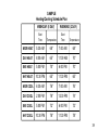
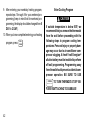
INSTALLATION &
OPERATION GUIDE
1F92W-51
Multi-stage/Heat Pump Electronic
Digital Thermostat
WHITE-RODGERS
Operator: Save this booklet for future use!
About Your New Thermostat . . .
Your new White-Rodgers Digital Multi-stage/Heat Pump Thermostat uses the technology of a solid-state
microcomputer to provide precise time/temperature control. This thermostat offers you the flexibility to
design heating and cooling programs that fit your needs.
Please read this manual thoroughly before operating or programming your thermostat. If you have
questions, contact us at the address shown on the back cover of this manual.
2
In This Guide . . .
YOUR NEW THERMOSTAT’S
FEATURES ..................................................
PRECAUTIONS .................................................
THE THERMOSTAT’S SPECIFICATIONS .......
INSTALLING YOUR THERMOSTAT ................
NEW INSTALLATION
Select Thermostat Location
Route Wires to Location
REPLACEMENT INSTALLATION
Remove Old Thermostat
Attach Subbase to Wall
SYSTEM CONFIGURATON
Set Option Switches
CHECK THERMOSTAT OPERATION
Fan Operation
Heating System Operation
Cooling System Operation
LOCKOUT BYPASS OPTION
Compressor Long Term Cycle Protection
Compressor Short Term Cycle Protection
4
5
6
7
OPERATING YOUR THERMOSTAT ............... 22
PARTS OF THE THERMOSTAT
The Back Of the Thermostat Body
The Display
The Thermostat Buttons
OPERATING FEATURES
PROGRAMMING YOUR
THERMOSTAT ........................................... 34
PLANNING FOR YOUR NEEDS
ENTERING YOUR PROGRAM
Set Current Time and Day
Enter Heating Program
Enter Cooling Program
CHECK YOUR PROGRAMMING
QUESTIONS AND ANSWERS ........................ 44
3
YOUR NEW THERMOSTAT’S FEATURES
• Five-day/two-day programming capability
• Adjustable cycle times
• Simultaneous heat and cool program storage
• 9 volt Energizer® alkaline battery backup
• Four separate time and temperature settings
per 24-hour period
• Compressor long term cycle protection
• Up to 2 stages of heat and up to 1 stage of cool
• Blower delay in the cooling cycle
• Computed Energy Management Recovery
(EMR)
• Preprogrammed temperature control
• Automatic changeover (operator selectable)
• Two hour temperature override
• Manual program override (HOLD temperature)
• “Advance Program” button
• Armchair programming capability
• LCD displays continuous setpoint, time, and
room temperature
4
• Compressor short cycle protection
• Visual prompting during operation
• Programmable blower control
• Temperature range 40° to 99°F
• °F/°C convertibility
• Electric Heat (installer-selectable)
PRECAUTIONS
If in doubt about whether your wiring is millivolt, line,
or low voltage, have it inspected by a qualified
heating and air conditioning contractor, electrician,
or someone familiar with basic electricity and wiring.
Do not exceed the specification ratings.
All wiring must conform to local and national electrical codes and ordinances.
This control is a precision instrument, and should be
handled carefully. Rough handling or distorting components could cause the control to malfunction.
! WARNING
Do not use on circuits exceeding specified
voltage. Higher voltage will damage control
and could cause shock or fire hazard.
Do not short out terminals on gas valve or
primary control to test. Short or incorrect
wiring will burn out thermostat and could
cause personal injury and/or property
damage.
! CAUTION
To prevent electrical shock and/or equipment damage, disconnect electric power to
system, at main fuse or circuit breaker box,
until installation is complete.
5
THE THERMOSTAT’S SPECIFICATIONS
THIS CONTROL IS DESIGNED FOR USE WHERE BOTH SIDES OF THE TRANSFORMER ARE
PRESENT AT THE THERMOSTAT (both the hot and common sides of the 24 VAC end of the
transformer.)
ELECTRICAL DATA
Electrical Rating:
20 to 30 VAC 50/60 Hz.
0.01 to 1.5 Amps (Load per terminal)
2.5 Amps Maximum Total Load (All terminals
combined)
Anticipation:
Heating 4 to 40
Cooling 4 to 40
Auxiliary 4 to 40
STAGING DATA
Up to 3 heating stages
Up to 1 cooling stage
6
THERMAL DATA
Setpoint Temperature Range:
40°F to 99°F (4°C to 37°C)
Operating Ambient Temperature Range:
32°F to 105°F
Operating Humidity Range:
0 to 90% RH (non-condensing)
Shipping Temperature Range:
-40°F to 150°F
ACCESSORIES
Thermostat Guard:
W. R. Part No. F29-0198 (clear)
or F29-0238 (opaque)
INSTALLING YOUR THERMOSTAT
NEW INSTALLATION
WE RECOMMEND THAT YOU PROGRAM THE
THERMOSTAT WITH BATTERY INSTALLED BEFORE ATTACHING ON SUBBASE. SEE OPERATION SECTION FOR PROGRAMMING INSTRUCTIONS.
SELECT THERMOSTAT LOCATION
Proper location insures that the thermostat will
provide a comfortable building temperature. Observe the following general rules when selecting
a location:
1. Locate thermostat about 5 ft. above the floor.
2. Install thermostat on a partitioning wall, not on an
outside wall.
3. Never expose thermostat to direct light from
lamps, sun, fireplaces or any temperature radiating equipment.
4. Avoid locations close to windows, adjoining outside walls, or doors that lead outside.
5. Avoid locations close to air registers or in the
direct path of air from them.
6. Make sure there are no pipes or duct work in that
part of the wall chosen for the thermostat location.
7. Never locate thermostat in a room that normally
warmer or cooler than the rest of the building.
8. Avoid locations with poor air circulation, such as
behind doors or in alcoves.
ROUTE WIRES TO LOCATION
NOTE
All wiring must conform with local and national
electrical codes and ordinances.
7
1. Probe for obstructions in partition before drilling
1
⁄2” hole in wall at selected location. Take up
quarter round and drill a small guide hole for
sighting (see fig. 1). From basement, drill 3⁄4” hole
in partition floor next to guide hole. In buildings
without basements, drill 1⁄2” hole through ceiling
and into partition from above (see fig. 1).
2. Through this hole drop a light chain, or 6” chain
attached to a strong cord. Snag cord in basement
with hooked wire. In buildings without basements, drop cord through hole in ceiling and
down partitioning; snag cord at the thermostat
location.
3. Attach thermostat wires to cord and pull wires
through hole in wall so that 6” of wire comes out
of the wall.
8
1⁄2” hole for
thermostat wire
Stout cord with 6”
chain attached
Baseboard
strip moulding
Approximately
5 feet from floor
1⁄4” guide hole
for sighting
Quarter round
removed
3⁄4” hole in floor of partition
Hooked wire for snagging chain
Figure 1. Routing thermostat wires
REPLACEMENT INSTALLATION
REMOVE OLD THERMOSTAT
1. Shut off electricity at the main fuse box until
installation is complete. Verify power is off
with a voltmeter.
2. Remove the front cover of the old thermostat. With wires still attached, remove
wall plate from the wall.
3. If the old thermostat has a wall mounting
plate, remove the thermostat and the wall
mounting plate as an assembly.
TABLE 1. WIRE IDENTIFICATION LABELS
1
G
2
C
3
L
4
R
5
O
6
B
7
E1
8
E2
G
1
C
2
L
3
R
4
O
5
B
6
E1
7
E2
8
9
Y1
10
Y2
11
W1
12
W2
13
W3
14
S1
15
S2
16
S3
Y1
9
Y2
10
W1
11
W2
12
W3
13
S1
14
S2
15
S3
16
4. Use the Cross Reference Guide to find the
thermostat type you are replacing.
5. Identify each wire attached to the old thermostat using the labels enclosed with the new
thermostat (see Table 1). Record the identification of the wire on the corresponding blank
in Table 2.
6. Disconnect the wires from old thermostat one at
a time. Pull at least 6 inches of wire out of the
wall. DO NOT LET WIRES FALL BACK INTO
THE WALL.
7. Install new thermostat using the following procedures.
9
TABLE 2. TERMINAL REFERENCE
10
LABEL
NUMBER
NEW THERMOSTAT
TERMINAL
DESIGNATION
(1)
(2)
(3)
(4)
(5)
(6)
(7)
G
C
L
R
O
B
E1
(8)
E2
(9)
(10)
(11)
(12)
(13)
Y1
Y2
W1
W2
W3
FUNCTION
Fan Output
Transformer 24 VAC Common
(this terminal not used)
Transformer 24 VAC Hot
Changeover Output (Cooling)
Changeover Output (Heating)
Emergency Heat Relay (cycles on
1st stage in Emergency Mode)
Emergency Heat Relay (continually
energized in Emergency Mode)
Stage 1 Cool
(this terminal not used)
Stage 1 Heat (Compressor)
Stage 2 Heat (Auxiliary)
(this terminal not used)
OLD THERMOSTAT
TERMINAL
DESIGNATION
ATTACH SUBBASE TO WALL
1. Remove the packing material from the thermostat. Place the fingers of one hand on the center
top and bottom portion of the thermostat. Grasp
the subbase in the other hand on the top and
bottom center, and gently pull straight out (see
fig. 2). The thermostat has pin and socket connectors. Forcing or prying on the thermostat will
cause damage to the unit.
2. Connect wires beneath terminal screws on subbase using wiring schematic for your particular
application (see figs. 3 through 6).
then tighten screws. (Leveling is for appearance
only and will not affect thermostat operation.) If
you are using existing mounting holes, or if holes
drilled are too large and do not allow you to
tighten subbase snugly, use plastic expansion
plugs to secure subbase.
6. Push excess wire into wall and plug hole with a
fire-resistant material (such as fiberglass insulation) to prevent drafts from affecting thermostat
operation.
(Instructions continue on page 16).
3. Place subbase over hole in wall and mark
mounting hole locations on wall using subbase
as a template.
4. Move subbase out of the way. Drill mounting
holes.
5. Fasten subbase loosely to wall, as shown in fig.
3, using two mounting screws. Place a level
against bottom of subbase, adjust until level, and
11
! WARNING
! CAUTION
DO NOT EXCEED MAXIMUM VOLTAGE OR
CURRENT RATINGS. FIRE, PERSONAL INJURY, AND/OR EQUIPMENT DAMAGE
COULD RESULT.
To prevent electrical shock and/or equipment damage, disconnect electrical power
at the main fuse box until installation is
complete. Verify power is off with a voltmeter.
Expansion
plugs
Connect wires under
terminal screws
Mounting
hole
S1 S2 S3
O
B
Y1
Y2
C
G
9-pin connector
W1
E1
E2
L
R
W2
W3
4-pin connector
Pull wires through
this opening
Figure 3. Subbase
12
Mounting
hole
NOTE
The following wiring diagrams show typical terminal identification and wiring. For proper installation, refer to the
original manufacturers' instructions.
Thermostat
Control
Circuit
THERMOSTAT
B
O
Y1
G
E1
E2
W1
W2
C
R
SYSTEM
Changeover
Energized
In Heat
Fan
Relay
Emergency
Relay
Switched
Output
Heat
Relay
Stage 2
Hot
24 VAC
Changeover
Energized
In Cool
Compressor
Contactor
Stage 1
Emergency
Relay
Constant
Output
Heat
Relay
Stage 1
120 VAC
Neutral
TRANSFORMER
Figure 4. Typical wiring diagram for single transformer systems
13
NOTE
IF SAFETY CIRCUITS ARE IN ONLY ONE OF THE
SYSTEMS, REMOVE THE TRANSFORMER OF THE
SYSTEM WITH NO SAFETY CIRCUITS.
Thermostat
Control
Circuit
THERMOSTAT
CUT AND
TAPE OFF!
Hot
120 VAC
24 VAC
Neutral
TRANSFORMER
B
O
Y1
G
W1
E2
E1
W2
C
R
SYSTEM
Changeover
Energized
In Heat
Fan
Relay
Changeover
Energized
Compressor
Contactor
Heat
Relay
In Cool
Stage 1
Stage 1
Emergency
Relay
Switched
Output
Heat
Limit or
Relay
Safety
Stage 2
Switches
Emergency
Relay
Constant
Output
TRANSFORMER
Hot
24 VAC
120 VAC
Limit or
Safety
Switches
Neutral
HEAT PUMP SYSTEM
TWO COMMONS MUST
BE JUMPERED TOGETHER!
AUXILIARY HEATING SYSTEM
DEPENDING ON SYSTEM REQUIREMENTS, REPLACE WITH A
75VA TRANSFORMER, IF NEEDED
Figure 5. Typical wiring diagram for two transformer systems with NO safety circuits
14
NOTE
! CAUTION
Relay contacts shown are thermostatically operated. The
accessory relay scheme is required when safety circuits
exist in both systems.
Polarity must be observed. If the HOT
side of the second transformer is
jumpered to the COMMON side of the
first transformer a short will be made.
Damage to equipment will occur when
power is restored.
Thermostat
Control
Circuit
THERMOSTAT
B
O
Y1
G
W1
E2
E1
W2
C
R
SYSTEM
Changeover
Energized
In Heat
Fan
Relay
Changeover
Energized
Compressor
Contactor
Heat
Relay
In Cool
Stage 1
Stage 1
HEAT PUMP SYSTEM
TWO COMMONS MUST
BE JUMPERED TOGETHER!
Emergency
Relay
Switched
Output
Heat
Relay
Stage 2
Emergency
Relay
Constant
Output
AUXILIARY
HEATING SYSTEM
Limit or
Safety
Switches
24 VAC
24 VAC
Accessory
Relay N.O.
Contact
Limit or
Safety
Switches
Limit or
Safety
Switches
Hot
120 VAC
Neutral
AUXILIARY
HEATING
TRANSFORMER
HEAT PUMP
TRANSFORMER
Hot
24 VAC
Limit or
Safety
Switches
120 VAC
Neutral
Figure 6. Typical wiring diagram for two transformer systems with safety circuits in BOTH systems
15
ATTACH THERMOSTAT TO SUBBASE
WE RECOMMEND THAT YOU SET OPTION
SWITCHES TO DESIRED POSITION BEFORE ATTACHING ON SUBBASE (see OPERATION). WE
ALSO RECOMMEND THAT YOU PROGRAM THE
THERMOSTAT WITH BATTERY INSTALLED BEFORE ATTACHING ON SUBBASE (see OPERATION section for programming instructions).
USE
SYSTEM
HEAT-OFF-COOL-AUTO
TO TURN THERMOSTAT OFF BE-
FORE ATTACHING TO WALL. FAILURE TO TURN
OFF THERMOSTAT BEFORE ATTACHING TO
WALL MAY CAUSE EQUIPMENT DAMAGE DUE
TO RAPID COMPRESSOR CYCLING.
To attach thermostat to subbase, line up the plastic
snap guides at the top of the thermostat and the 4
connector pins on the thermostat with the connectors near the top right section of the subbase (when
viewed from the front). Gently pivot the thermostat
down until the 9-pin connectors and the plastic
16
snaps lock into place (see fig. 7). Be gentle when
attaching thermostat. If the thermostat does not
seem to be attaching to the subbase easily, make
sure that the connector pins and plastic snaps are
properly aligned, and that excess wire is pushed into
the wall. Damage to the thermostat may occur if
force is used.
ENGAGE TWO UPPER GUIDES; PIVOT DOWN
Figure 7. Attaching thermostat to subbase
SYSTEM CONFIGURATION
SET OPTION SWITCHES
NOTE
1. Single Stage Compressor Heat Pump — with
reversing valve energized through B or O terminals
ANY TIME AN OPTION SWITCH IS CHANGED,
THE 9 VOLT ENERGIZER® BATTERY MUST BE
REMOVED FOR A MINIMUM OF 2 MINUTES.
4-pin connector
Battery
W1
Y1
Field jumper W1 & Y1
4
Switch #1 OFF
Switch #2 OFF
Switch #3 OFF
Switch #4 (see step 6)
ON
1
2
3
2. Two Compressor (Split) System
W1
Y1
Field jumper W1 & Y1
4
Switch #1 OFF
Switch #2 ON
Switch #3 OFF
Switch #4 (see step 6)
ON
W18
1
Option switches
2
3
9-pin connector
Figure 8. Back of thermostat
17
3. Multi-stage (Fossil Fuel) System — up to 2
heat stages and 1 cool stage
5. Automatic Changeover from Heat to Cool
ON
ON
1
2
3
4
Switch #1 ON
Switch #2 OFF
Switch #3 OFF
Switch #4 (see step 6)
4. Multi-stage (Electric Heat) System — up to 2
heat stages and 1 cool stage
ON
1
18
2
3
4
Switch #1 ON
Switch #2 ON
Switch #3 (see step 5)
Switch #4 (see step 6)
1
2
3
4
Switch #1 (see steps 1-4)
Switch #2 (see steps 1-4)
Switch #3 (see step 5)
Switch #4 ON
NOTE
The battery maintains the stored program in the
event of a power failure. When attached to the wall
with 24 VAC power applied, the thermostat will
function normally without the battery. However, the
program will be lost in the event of power interruption
or failure if the battery is not installed. When power
is restored, the thermostat will automatically maintain a temperature of 64°F or a cooling temperature
of 82°F (factory preprogrammed) as needed.
CHECK THERMOSTAT OPERATION
When checking thermostat, option switch #4 for
automatic changeover must be in the OFF position.
This will allow temporary setting of heat set points
above cool settings. After system checkout, reset
option switch to ON position if automatic changeover
is desired (see SET OPTION SWITCHES).
FAN OPERATION
1. Turn on power to the system. If the auxiliary heat
source has a standing pilot, be sure to light it.
2. Press
FAN
ON
– AUTO
until FAN
is displayed. The
NOTE
FAN
ON
– AUTO
until FAN
1. Press
SYSTEM
HEAT-OFF-COOL-AUTO
until HEAT is displayed. (It should
already be displayed.)
2. Press
to adjust thermostat to 99°F. All
stages of the heating system should come on
within approximately five minutes. However, if
the PUMP LED is flashing, the compressor lockout feature is operating (see Lockout Bypass
Option to temporarily override the compressor
lockout feature during testing).
3. Press
SYSTEM
HEAT-OFF-COOL-AUTO
until EMER is displayed. Repeat
step 2.
blower should begin to operate.
3. Press
HEATING SYSTEM OPERATION
4. To program the thermostat, see PROGRAMMING YOUR THERMOSTAT.
is displayed. The
blower should stop operating within approximately one minute.
19
COOLING SYSTEM OPERATION
! CAUTION
To prevent compressor and/or property
damage, if power to the compressor has
been off or interrupted for more than 1
hour and the outdoor temperature is below 50°F, DO NOT operate the system for
at least the amount of time the compressor was off! This will allow the compressor heaters to warm the compressor oils
to avoid damage due to slugging.
1. Press
SYSTEM
HEAT-OFF-COOL-AUTO
until COOL is displayed.
2. Press
to adjust thermostat to 40°F. The
cooling system should come on within approximately five minutes. However, if the fan is running but the compressor is not, the compressor
lockout feature is operating (see Lockout By20
pass Option to temporarily override the compressor lockout feature during testing).
3. To program the thermostat, see PROGRAMMING YOUR THERMOSTAT.
After heating and cooling system have been checked
and are running properly, determine if automatic
changeover is desired. When option switch #4 is in
the proper position, automatic changeover is enabled by pressing
SYSTEM
HEAT-OFF-COOL-AUTO
until AUTO is displayed
(see SET OPTION SWITCHES). In the AUTO mode,
the setpoint temperature is not displayed.
LOCKOUT BYPASS OPTION
! CAUTION
FOR QUALIFIED SERVICE TECHNICIANS’
USE ONLY. OPERATORS SHOULD NOT USE
THIS FEATURE DUE TO POSSIBILITY OF
EQUIPMENT OR PROPERTY DAMAGE, OR
PERSONAL INJURY.
DO NOT USE THE LOCKOUT BYPASS OPTION UNLESS THE COMPRESSOR OIL
HEATERS HAVE BEEN OPERATIONAL FOR
6 HOURS AND THE SYSTEM HAS NOT BEEN
OPERATIONAL FOR AT LEAST 5 MINUTES.
COMPRESSOR LONG TERM CYCLE
PROTECTION
To protect the compressor from potential damage
due to temperature change of crankcase oil, this
thermostat has a built-in time delay of one hour less
than the power loss to the unit (up to 12 hours
maximum lockout). During this time, auxiliary heat
will be used when necessary to maintain setpoint
temperature. DO NOT attempt to override this delay
feature before crankcase temperature has stabilized (for example, if power has been out for three
hours, the compressor should remain locked out for
two hours).
COMPRESSOR SHORT TERM CYCLE
PROTECTION
This thermostat has a built-in short term (5-minute)
time delay. During this 5-minute period, the thermostat will lock out the compressor to allow head
pressure to stabilize. If you want to override this
feature while testing thermostat operation, simply
press
ADV
PRGM
and
HOLD
TEMP
at the same time at initial
startup.
21
OPERATING YOUR THERMOSTAT
Before you begin programming your new thermostat, you should be familiar with its features and with
the display and the location and operation of the
thermostat buttons. The information in this section
will help you become familiar with your thermostat so
that you can easily program it.
Your thermostat consists of two parts: the thermostat body and the subbase.
The subbase is attached to the wall, but you can
remove the thermostat body for easy programming.
To remove the thermostat body from the subbase,
grasp the thermostat body and gently pull it straight
out from the subbase (see fig. 9). To attach the
thermostat body, line up the four terminal pins on the
upper section of the thermostat back with the matching connector on the subbase. Insert these, then
gently pivot the thermostat body down to connect the
! CAUTION
Use
SYSTEM
HEAT-OFF-COOL-AUTO
to turn the thermostat OFF
before removing or attaching the thermostat body. Equipment damage and/or personal injury could occur.
PULL STRAIGHT OUT
Figure 9. Removing thermostat from subbase
22
nine pin connectors on the lower portion of the
thermostat back. Gently push until the snap connectors engage (see fig. 10). DO NOT FORCE OR PRY
THE THERMOSTAT, as this may damage the unit.
ENGAGE TWO UPPER GUIDES; PIVOT DOWN
Figure 10. Attaching thermostat to subbase
PARTS OF THE THERMOSTAT
The Back of the Thermostat Body
Turn the thermostat body over. On the back are the
9 volt Energizer® alkaline battery and the option
switches.
1. The 9 volt Energizer® alkaline battery provides
power to the thermostat when the 24 VAC power
is interrupted (for example, when you remove the
thermostat from the wall for programming). A
fresh battery will maintain the stored program for
approximately one week. If power loss is long
enough for the program to be lost, the thermostat
will automatically maintain a factory preprogrammed heating temperature of 64°F and a
cooling temperature of 82°F after power is restored. You must re-program the thermostat if
this happens.
If the word BAT is flashing in the display window,
the battery is low and should be replaced with a
fresh 9 volt Energizer® alkaline battery. The
23
battery will provide power for all functions. If the
word BAT is displayed continuously (non-flashing), the thermostat is not being supplied with 24
VAC power and is being powered by the battery
alone.
! CAUTION
Use
SYSTEM
HEAT-OFF-COOL-AUTO
to turn thermostat OFF before
removing thermostat from the wall to replace the battery.
2. You may adjust option switch #4 for automatic
changeover from heating to cooling (see OPERATING FEATURES).
Other than
and
, the buttons are located
behind the thermostat door. To open the door, use
your fingernail in the indentation at the top center of
the door. Pull the door out, then swing the door down
on its hinges.
24
Following are brief descriptions of the display and
the thermostat buttons.
The Display
1 Continuously displays system mode (HEAT,
EMER, OFF, COOL, AUTO, HOLD). During
programming, the program period is displayed
(MOR, DAY, EVE, NHT).
2 Alternately displays room temperature (F de-
notes degrees Fahrenheit and C denotes degrees Celsius) and time of day (A denotes AM
time and P denotes PM time).
3 Displays the setpoint temperature.
4 5 DAY indicates that the displayed program is
the weekday program. 2 DAY indicates that the
displayed program is the weekend program.
5 The word BAT flashes on the display when the
9 volt alkaline battery is weak and should be
replaced. The word BAT will be displayed continuously (non-flashing) when the thermostat is
operating on battery power only.
6 FAN
is displayed when the blower is operating continuously, regardless of heating or cooling system cycling. FAN
is displayed during
automatic fan operation (when the blower cycles
with the heating or cooling system).
EMER.
5 DAY
FAN
AUX.
SYSTEM
HEAT-OFF-COOL-AUTO
FAN
ON
1
2 DAY
4
- AUTO
2
FAN
6
TIME
FWD
SET
CLOCK
VIEW
PRGM
HOLD
TEMP
TIME
BACK
SET
DAY
RUN
PRGM
ADV
PRGM
3
3
5 DAY
4
BAT
5
FAN
6
2
25
The Thermostat Buttons and Lights
7 Sets the system mode (HEATing, EMERgency
backup, OFF, COOLing, or AUTOmatic
changeover [user selectable feature]).
8 Selects fan operation (see #6, previous page).
This button is also used to program the fan to run
continuously during a program period.
9 Runs display forward or backward through time,
day, or anticipation settings during programming.
10 Used with
TIME
FWD
and
TIME
BACK
to set current time
11 Used during programming to set the day of the
tion setting mode.
26
ming.
13 Used to start program operation after program-
ming. Also used to return thermostat to program
operation after being in HOLD mode.
14 Used to manually override programming to hold
at a selected temperature (when HOLD is displayed).
15 Used to advance thermostat program to the next
program period (for example, from the MOR
program to the DAY program).
16 (Blue arrow) Lowers temperature setting (40°F
and day of the week.
week. Also used with
12 Used to initiate or review thermostat program-
SET
CLOCK
or 4°C minimum).
17 (Red arrow) Raises temperature setting (99°F
to enter anticipa-
or 37°C maximum)
setpoint temperature — there is a 5 to 10
minute startup delay on the first emergency
cycle). AUX light indicates that the auxiliary
system is operating.
18 EMER light indicates that the system is in the
emergency mode (the heat pump compressor
is off and the auxiliary system is maintaining
16
18
17
EMER.
5 DAY
FAN
AUX.
7
8
SYSTEM
HEAT-OFF-COOL-AUTO
FAN
ON
- AUTO
9
TIME
FWD
SET
CLOCK
VIEW
PRGM
HOLD
TEMP
TIME
BACK
SET
DAY
RUN
PRGM
ADV
PRGM
10 11 12 13 14 15
27
OPERATING FEATURES
Now that you are familiar with the thermostat display
and buttons, read the following information to learn
about the many features of the thermostat.
• COMPUTED ENERGY MANAGEMENT RECOVERY (EMR) - The thermostat’s microcomputer automatically calculates the time it will
take to change the temperature to the next
program setting. Then the thermostat will activate the heating or cooling system to change
the temperature so that the desired temperature is reached at the beginning of the next
program period. As an example of this feature,
assume that you have programmed your thermostat to provide an overnight heating temperature of 62°F, and that during the next program period, beginning at 6:00 AM, you have
programmed a temperature of 70°F. The thermostat will automatically activate the heating
28
system at about 5:00 AM, so that the programmed 70°F temperature is reached by about
6:00 AM.
• AUTOMATIC CHANGEOVER — You can set
the thermostat to automatically switch the system from heating to cooling as needed. First,
you must move option switch #4 (located on the
back of the thermostat body) to the ON position,
if it has not already been done. To do this, press
SYSTEM
HEAT-OFF-COOL-AUTO
until thermostat is OFF. Then, remove
the thermostat body from the wall. Check the
position of switch #4 (the last switch on the
right). If it is ON (up), simply put the thermostat
back on the wall and restore 24 VAC power. If
the switch is OFF (down), use a pencil or small
screwdriver to move the switch to the ON position (see figure at right). Leave the battery out of
the thermostat for at least two minutes, to allow
the thermostat to reset itself. DO NOT MOVE
ANY OTHER OPTION SWITCH, as it may
affect thermostat operation. Replace the battery, re-program the thermostat if necessary,
put the thermostat back on the wall, and use
SYSTEM
HEAT-OFF-COOL-AUTO
AUTOMATIC CHANGEOVER (ON)
ON
to set thermostat for desired opera1
tion. To set the thermostat for automatic
changeover after programming, press
SYSTEM
HEAT-OFF-COOL-AUTO
to set the thermostat to AUTO (the setpoint
display is blank in the AUTO mode). The system will now automatically switch between heating and cooling depending on the actual room
temperature.
79
78
77
76
75
74
73
COOLING TEMPERATURES
DEAD BAND 1°F
HEATING TEMPERATURES
2
3
4
Switch #1 set at installation (DO NOT CHANGE)
Switch #2 set at installation (DO NOT CHANGE)
Switch #3 set at installation (DO NOT CHANGE)
Switch #4 ON
NOTE
In the AUTO mode, the thermostat will not allow the
temperature separation between the highest heat
setting and the lowest cool setting to be less that 1°F.
For example, if the highest heat setting is 76°F, the
lowest cool setting cannot be below 77°F (see
diagram at left).
29
If the automatic changeover feature is enabled,
and you wish to disable it, press
SYSTEM
HEAT-OFF-COOL-AUTO
thermostat is OFF. Then, remove the thermostat body from the wall. Move the switch to the
ON position (see figure at right). Leave the
battery out of the thermostat for at least two
minutes, to allow the thermostat to reset itself.
DO NOT MOVE ANY OTHER OPTION
SWITCH, as it may affect thermostat operation.
Replace the battery, re-program the thermostat
if necessary, put the thermostat back on the
wall, and use
desired.
SYSTEM
HEAT-OFF-COOL-AUTO
AUTOMATIC CHANGEOVER (OFF)
until
to set the thermostat as
ON
1
2
3
4
Switch #1 set at installation (DO NOT CHANGE)
Switch #2 set at installation (DO NOT CHANGE)
Switch #3 set at installation (DO NOT CHANGE)
Switch #4 OFF
• TWO HOUR TEMPERATURE OVERRIDE —
Press
or
until the display shows the
temperature you want. The thermostat will override current programming and keep the room
temperature at the selected temperature for two
hours. After two hours, the thermostat will automatically revert to the program.
• HOLD TEMPERATURE — The thermostat can
hold any temperature within its range for an
indefinite period, without reverting to the pro-
30
gram. Press
HOLD
TEMP
. HOLD will be displayed.
Then choose the desired hold temperature by
pressing
or
. The thermostat will
hold the room temperature at the selected setting until you press
HOLD
TEMP
to start program op-
eration again. This feature is ideal for energy
conservation when the building is unoccupied
for an extended period of time.
• °F/°C CONVERTIBILITY — Press
TIME
BACK
TIME
FWD
and
at the same time until the temperature
display is in °C (Celsius). To display °F, repeat
the process.
• ADJUSTABLE HEATING AND COOLING
CYCLE TIMES (ANTICIPATION) — If the heating/cooling system is turning on and off too
often (short cycles) or not often enough (long
cycles), you may want to adjust the anticipation
setting.
! CAUTION
An anticipation setting of less than 10 may
cause decreased compressor life.
To adjust HEAT anticipation, press
SET
DAY
SET
CLOCK
and
at the same time. The display will show
HEAT 18. You may select any anticipation
setting from 4 to 40 (note that for add-on heat
pump systems, a minimum anticipation of
10 is recommended). When you adjust anticipation, increase or decrease the displayed number by only one or two digits, then let the system
run for a while to see if the adjustment is
sufficient. If the heat cycles are too short, press
TIME
FWD
to increase the cycle time. If the heat
31
cycles are too long, press
TIME
BACK
continuously (non-flashing), 24 VAC power is
not being supplied and the thermostat is working on battery power only.
to decrease
the cycle time. To set COOL anticipation, press
SET
CLOCK
and
SET
DAY
at the same time again. The
display will show COOL 14 (factory
preprogrammed cooling anticipation). Use
TIME
FWD
and
TIME
BACK
to adjust anticipation. To set
AUXILIARY heat anticipation (not applicable to
multi-stage use), press
SET
CLOCK
and
SET
DAY
at the
same time again. The display will show AUX 8
(factory preprogrammed auxiliary anticipation).
Use
Press
•
32
TIME
FWD
RUN
PRGM
and
TIME
BACK
to adjust anticipation.
to return to your program.
LOW BATTERY INDICATOR — The word BAT
will flash on the display if the battery is low and
should be replaced. When BAT is displayed
•
COMPRESSOR SHORT CYCLE PROTECTION — To protect your compressor from potential damage due to rapid cycling, this thermostat
has a built-in delay of 5 minutes between cooling
cycles. The following may cause a time delay in
COOL or HEAT:
a) Return of power after a momentary power
outage.
b) Pressing
SYSTEM
HEAT-OFF-COOL-AUTO
to change operating
modes.
c) Pressing
or
to create a call for
COOL or HEAT too soon after a previous
call.
During lockout in the COOL mode, the blower
will operate, but compressor operation will be
delayed.
• COMPRESSOR LONG TERM CYCLE PROTECTION — If your system begins to operate
too soon after an extended power outage, the
compressor may be damaged due to crankcase
oil temperature change. This thermostat has a
built-in time delay of one hour less than the
power loss (up to 12 hours). When power is
restored to the system, heaters in the system
will begin to heat the crankcase oils. The
thermostat’s time delay will lock out the compressor to prevent its operation until the compressor oil is sufficiently warmed. During the
lockout time period, the auxiliary heating system will operate to maintain setpoint temperature.
• SYSTEM INDICATOR LIGHTS — The lights
on the upper right part of the thermostat indicate
system operation (see PARTS OF THE THERMOSTAT for specific descriptions of what each
light indicates).
• PROGRAMMABLE BLOWER CONTROL —
You may program the fan blower to run continuously during any given program period, regardless of the cycling of the heating or cooling
system. During programming, after entering the
time and temperature for the time period, press
FAN
ON
– AUTO
until FAN
constant fan, press
is displayed. To override
FAN
ON
– AUTO
until FAN
is
displayed.
For example, if a power outage of three hours
occurs, the compressor will be locked out for
two hours.
33
PROGRAMMING
Auxiliary heat is functional during the compressor lockout and can be used as needed to
maintain room temperature.
PROGRAMMING YOUR THERMOSTAT
PROGRAMMING
PROGRAMMING
Now you are ready to program your thermostat. This
section will help you plan and program your thermostat to meet your needs.
For maximum comfort and efficiency, keep the following guidelines in mind when planning your program.
• When heating (cooling) your building, program
the temperatures to be cooler (warmer) when
the building is vacant or during periods of low
activity.
• During early morning hours, the need for cooling is usually minimal.
PLANNING FOR YOUR NEEDS
This thermostat will store separate heating and
cooling programs for five-day (weekday) and twoday (weekend) operation. Usually, the five-day program is set to run Monday through Friday, and the
34
two-day program is set to run Saturday and Sunday.
However, you may choose any five consecutive
days to be your weekday program days (such as
Sunday through Thursday; in this case, your weekend program would run on Friday and Saturday).
First, you should answer the following questions to
help you decide what your needs are. If you are
using the thermostat for a commercial application (a
store, office building, etc.), answer questions 1
through 4. If you are using the thermostat in your
home, answer questions 5 through 8. Keep in mind
that you should plan for both weekday and weekend
programs.
FOR COMMERCIAL APPLICATIONS:
1a. What time does the first person arrive at the
building in the morning?
b. What temperature should the building be at this
time? (heating? cooling?) These will be your
MOR (morning) temperature settings.
IN YOUR HOME:
5a. What time does the first person get up in the
morning?
2a. What time do the building occupants reach a
maximum activity level (using lights, equipment,
meeting rooms, etc.)?
b. What temperature should the house be at this
time? These will be your MOR (morning) temperature settings.
b. What temperature should the building be at this
time? These will be your DAY temperature settings.
6a. What time does the last person leave the house
in the morning?
3a. What time do the building occupants reach a
minimum activity level (limited personnel in building)? These will be your EVE (evening) temperature settings.
b. What temperature should the building be at this
time?
4a. What time does the building become vacant?
b. What temperature should the house be at this
time? These will be your DAY temperature settings.
7a. What time does the first person arrive home in
the evening?
b. What temperature should the house be at this
time? These will be your EVE (evening) temperature settings.
b. What temperature should the building be at this
time? These will be your NHT (night) temperature settings.
35
8a. What time does the last person go to bed at
night?
NOTE
b. What temperature should the house be at this
time? These will be your NHT (night) temperature settings.
To operate properly in the AUTO mode, there must
be a minimum 1°F separation between the highest
heat temperature and the lowest cool temperature
(see diagram below).
Now look at the factory preprogrammed times and
temperatures shown below. If this program will suit
your needs, simply press
RUN
PRGM
to begin running the
factory preset program.
If you want to change the preprogrammed times and
temperatures, do the following.
Heating Program for ALL days of the Week:
PERIOD
MOR
DAY
EVE
NHT
36
79
78
77
76
75
74
73
TIME
5:00 AM
9:00 AM
4:00 PM
10:00 PM
TEMP
70
70
70
64
COOLING TEMPERATURES
DEAD BAND 1°F
HEATING TEMPERATURES
Determine the time periods and heating and cooling
temperatures for your weekday program. You must
program 4 periods for each day (MOR, DAY, EVE,
and NHT). However, you may use the same heating
Cooling Program for ALL Days of the Week:
PERIOD
MOR
DAY
EVE
NHT
TIME
5:00 AM
9:00 AM
4:00 PM
10:00 PM
TEMP
78
82
78
78
and cooling temperatures for consecutive time periods. You can choose start times, heating temperatures, and cooling temperatures independently for
both weekday and weekend programs (for example,
you may select 5:00 AM and 70° as the weekday
MOR heating start time and temperature, and choose
7:00 AM and 76° as the weekday MOR cooling start
time and temperature). Use the table on the next
page to plan your program time periods, and the
temperatures you want during each period. You may
also want to look at the sample program table to get
an idea of how the thermostat can be programmed.
ENTERING YOUR PROGRAM
Follow these steps to enter the heating and cooling
programs you have selected.
NOTE
We recommend that you remove the thermostat
from the wall for programming (especially for entering cooling programming). A fresh 9 volt Energizer®
alkaline battery must be installed to perform off-wall
programming. BE SURE TO PRESS
SYSTEM
HEAT-OFF-COOL-AUTO
TO
TURN THERMOSTAT OFF BEFORE REATTACHING TO SUBBASE!
You cannot program the thermostat with the SYSTEM SWITCH in the AUTO position.
(Instructions continue on page 40).
37
Heating/Cooling Schedule Plan
WEEKDAY (5 DAY)
Start
Time
MOR HEAT
DAY HEAT
EVE HEAT
NHT HEAT
MOR COOL
DAY COOL
EVE COOL
NHT COOL
38
Temperature
WEEKEND (2 DAY)
Start
Time
Temperature
SAMPLE
Heating/Cooling Schedule Plan
WEEKDAY (5 DAY)
WEEKEND (2 DAY)
Start
Time
Temperature
Start
Time
Temperature
MOR HEAT
5:30 AM
68°
7:00 AM
68°
DAY HEAT
8:00 AM
65°
11:00 AM
70°
EVE HEAT
5:00 PM
70°
6:00 PM
70°
NHT HEAT
10:30 PM
65°
11:30 PM
65°
MOR COOL
6:30 AM
76°
7:00 AM
76°
DAY COOL
2:00 PM
78°
12:30 PM
74°
EVE COOL
5:00 PM
72°
6:00 PM
72°
NHT COOL
10:30 PM
78°
11:30 PM
78°
39
Set Current Time and Day
1. Press
SET
CLOCK
5. Press
once. The display will show min-
utes only.
SET
DAY
once. The display will show the day
of the week as an abbreviation (MO for Monday,
TU for Tuesday, etc.).
6. Press and hold either
EXAMPLE:
TIME
FWD
or
TIME
BACK
until you
reach the current day of the week.
2. Press and hold either
TIME
FWD
or
TIME
BACK
until you
reach the correct minutes.
3. Press
SET
CLOCK
show the hour only.
EXAMPLE:
TIME
FWD
or
TIME
BACK
until you
reach the correct hour and AM/PM designation
(AM begins at midnight; PM begins at noon).
40
RUN
PRGM
once. The display will show the
correct time and room temperature alternately.
once. The display window will
4. Press and hold either
7. Press
Enter Heating Program
During programming, if you don’t press any buttons
for 5 minutes, the thermostat will enter the HOLD
mode and will maintain a constant temperature. The
display will revert to the alternating time/temperature display. To resume programming after this
happens, press
VIEW
PRGM
until you are at the point
where you stopped programming. Then you may
continue to enter your programs normally. If you
want to stop programming at any time, simply press
RUN
PRGM
to resume program operation.
3. To change the displayed start time to your selected start time for weekday MOR heat program, press
1. Press
2. Press
SYSTEM
HEAT-OFF-COOL-AUTO
VIEW
PRGM
until HEAT is displayed.
once. 5 DAY (indicating weekday
program), and MOR, representing the morning
heating period, will appear in the display. Also
displayed are the currently programmed start
time for the MOR period and the currently programmed temperature.
EXAMPLE:
This display window shows that for the weekday
MOR period, the start time is 5:00 AM, and 64° is
the programmed temperature (this example reflects factory preprogramming).
or
TIME
BACK
until your selected
time appears. The time will change in 15 minute
increments.
4. Press
or
until you reach your selected weekday MOR heating temperature.
5. If you want the fan to run continuously during this
period, press
6. Press
5 DAY
TIME
FWD
VIEW
PRGM
FAN
ON
– AUTO
until FAN
is displayed.
. The currently programmed start
time and heating temperature for weekday DAY
will be displayed.
7. Repeat steps 3 through 5 to select the start time
and heating temperature for the weekday DAY
program.
8. Repeat steps 3 through 7 for the weekday EVE
and NHT heating programs.
41
9. After entering your weekday heating program,
repeat steps 1 through 8 for your weekend programming (keep in mind that for weekend programming, the display should be changed from 5
DAY to 2 DAY).
10. When you have completed entering your heating
program, press
RUN
PRGM
.
Enter Cooling Program
! CAUTION
If outside temperature is below 50°F, we
recommend that you remove the thermostat
from the wall before proceeding with the
following steps to program cooling temperatures. Personal injury or property damage may occur due to air conditioner compressor slugging. A fresh 9 volt Energizer®
alkaline battery must be installed to perform
off-wall programming. Programming away
from the wall should prevent accidental compressor operation. BE SURE TO USE
SYSTEM
HEAT-OFF-COOL-AUTO
TO TURN THERMOSTAT OFF BE-
FORE REATTACHING TO SUBBASE!
42
1. Press
SYSTEM
HEAT-OFF-COOL-AUTO
until COOL is displayed.
2. Follow the procedure for entering your heating
program, using your selected cooling times and
temperatures.
CHECK YOUR PROGRAMMING
Follow these steps to check your thermostat programming one final time before beginning thermostat operation.
1. Press
SYSTEM
HEAT-OFF-COOL-AUTO
2. Press and hold
until HEAT is displayed.
VIEW
PRGM
to view the heating period
times and temperatures in sequence for weekday, then weekend MOR, DAY, EVE, and NHT
program periods.
3. Press
RUN
PRGM
4. Press
SYSTEM
until COOL is displayed.
HEAT-OFF-COOL-AUTO
5. Repeat step 2 to check cooling temperatures.
6. Press
RUN
PRGM
to begin program operation.
YOUR THERMOSTAT IS NOW COMPLETELY
PROGRAMMED AND READY TO AUTOMATICALLY PROVIDE MAXIMUM COMFORT AND EFFICIENCY!
Press
SYSTEM
HEAT-OFF-COOL-AUTO
until OFF is displayed. Reattach
thermostat to subbase. Then press
SYSTEM
HEAT-OFF-COOL-AUTO
to
select the operation mode you want (HEAT, COOL,
AUTO). Press
FAN
ON
– AUTO
until FAN
is displayed
(automatic cycling).
.
43
QUESTIONS AND ANSWERS
1. How can I permanently change a part of my
program?
Press
VIEW
PRGM
until you reach the time/tempera-
ture schedule you want. Then press
and
TIME
FWD
and
TIME
BACK
or
to change the pro-
gram. See PROGRAMMING YOUR THERMOSTAT.
2. How can I have no change in temperature
from one time period to another?
Simply select the same temperature for each
consecutive time period. For example, you may
select the same weekday EVE cooling temperature as you did for weekday DAY, which means
the temperature will not change when the EVE
period begins. See PROGRAMMING YOUR
THERMOSTAT.
44
3. How can I finish my programming if the display has already changed to time/temperature?
During programming, if no buttons are pressed
for five minutes, the thermostat will enter the
HOLD mode and maintain a constant temperature. The display will change to the time/temperature mode. To resume programming, press
VIEW
PRGM
until you return to the point where you
stopped programming. Then you may continue
to program the thermostat normally. If you want
to stop programming at this point, press
RUN
PRGM
to
start the normal program function. See PROGRAMMING YOUR THERMOSTAT.
4. What happens if the electricity goes off or is
manually shut off?
6. What can cause the thermostat display to
freeze or go blank?
If you have not installed a 9 volt alkaline battery,
the display will go blank and the program will be
lost in approximately one minute. When electricity is restored, the thermostat will maintain a
heating temperature of 64°F and a cooling temperature of 82°F until you reenter your program.
Setpoint temperature will not be displayed.
A completely blank display may indicate that
power has been lost to the thermostat and the
backup battery is also dead. However, if there is
power to the thermostat and the display is blank
or frozen, static discharge is probably the cause.
If a fresh 9 volt Energizer® alkaline battery is
installed, the program will be maintained for
about one week with no 24 VAC power present
to the thermostat. See OPERATING YOUR
THERMOSTAT.
5. Why can’t I program the thermostat in the
AUTO mode?
The thermostat can only be programmed in the
HEAT and COOL modes. See PROGRAMMING
YOUR THERMOSTAT.
During periods of low humidity (especially during
cold weather), you may feel or see a spark
discharge when you touch the thermostat. This
may cause the program to be lost or the thermostat to display incorrectly. To correct this, remove
the thermostat from the wall and disconnect the
battery. Wait about one minute, then re-connect
the battery. The thermostat will revert to the
factory preset program until you re-program the
thermostat. If you don’t want to re-program the
thermostat immediately, press
SYSTEM
HEAT-OFF-COOL-AUTO
until
OFF is displayed and replace the thermostat on
45
to begin the
the heating temperature higher. To set a lower
cooling temperature, you must select a lower
heating temperature. See PROGRAMMING
YOUR THERMOSTAT.
factory preset program. Or you may re-program
the thermostat, then replace it on the wall.
8. The display is flashing BAT. What does this
mean?
To prevent further static discharge problems,
touch another object to release static build-up
before touching the thermostat. See OPERATING YOUR THERMOSTAT.
The 9 volt battery installed in the thermostat is
low and should be replaced with a fresh 9 volt
Energizer® alkaline battery. See OPERATING
YOUR THERMOSTAT.
7. Why won’t the setpoint temperature go to the
temperature I want?
9. The display shows a continuous (non-flashing) BAT. What does this mean?
In the AUTO mode, the highest heating setpoint
temperature you select must be at least 1°F
lower than the lowest cooling setpoint temperature you select (for example, if 70°F is your
lowest selected cooling temperature, you cannot
select a heating temperature any higher than
69°F). If such a conflict exists, you must set the
lowest cooling temperature higher in order to set
The thermostat is not being supplied with 24 VAC
power. The thermostat is operating on battery
power alone. See OPERATING YOUR THERMOSTAT.
the wall. Then press
SYSTEM
HEAT-OFF-COOL-AUTO
tem operation, and press
46
for desired sys-
RUN
PRGM
10. Why won’t the system turn on, even though
the thermostat display is functioning normally?
Either the compressor lockout feature is in operation or the thermostat is not currently calling
for heat or cool. Wait about 5 minutes for the
compressor lockout to expire. If the system is still
not running, read the cautionary statement below. Then, if conditions permit, use the
or
buttons to move the temperature above or
below the setpoint temperature. See OPERATING YOUR THERMOSTAT.
11. Why doesn’t the temperature change at the
time I programmed?
There may be a number of causes for this situation. The following are primary reasons.
•
The EMR function is operating. The EMR
function will automatically bring on the system automatically to bring the temperature
to the selected level by the beginning of the
next program period. See OPERATING
YOUR THERMOSTAT.
•
You have programmed the incorrect day or
time. Check your programming (be sure that
the times you programmed are correct AM
or PM times). See PROGRAMMING YOUR
THERMOSTAT.
•
The thermostat is in the HOLD mode. Press
! CAUTION
If the outside temperature is below 50°F, DO
NOT use
or
to move the temperature above or below the setpoint temperature. Property damage may result due to
compressor slugging.
RUN
PRGM
to start program operation. See OP-
ERATING YOUR THERMOSTAT.
47
•
The compressor lockout feature is operating; wait about 5 minutes for system to begin
running. See OPERATING YOUR THERMOSTAT.
12. Why does the blower fan keep running after
the system has turned off?
•
•
You have programmed the fan to run continuously during this period. See PROGRAMMING YOUR THERMOSTAT.
The blower delay feature is operating. This
energy saving feature continues to blow
conditioned air through the ducts after the
system has turned off, rather than letting the
air dissipate.
13. Why is the system turning on and off so
frequently (seldom)?
The anticipation setting is too low (high). To
change anticipation settings, see OPERATING
YOUR THERMOSTAT.
48
14. Between heating and cooling seasons, I want
to turn my system off. Can I do this without
affecting my thermostat programming?
Any time you wish to turn your system off, simply
press
SYSTEM
HEAT-OFF-COOL-AUTO
until OFF is displayed. This will
not affect your thermostat’s programming in any
way. To turn the system back on, press
SYSTEM
HEAT-OFF-COOL-AUTO
until HEAT, COOL, etc. is displayed. The system
will automatically begin operating according to
the current thermostat program, unless the thermostat is in the HOLD mode. See OPERATING
YOUR THERMOSTAT.
15. I live in an area where daylight savings time is
observed. How do I change the thermostat
clock twice a year without affecting thermostat programming?
To change your clock, follow the instructions for
setting current time and day. See ENTERING
YOUR PROGRAM. Thermostat programming is
not affected when you change the clock.
17. Do I have to re-program my thermostat after
I change the battery?
When the thermostat is on the wall and the
system has power, the thermostat is being powered by a 24v AC source. If power is lost, or if the
thermostat is removed from the wall, the program will be retained for approximately one
minute if there is no battery installed or if the
installed battery is dead. If you are changing the
battery after seeing a flashing BAT on the display, the installed battery may be dead. If you
remove the old battery and install a fresh one
within one minute, you may not lose your thermostat programming. After installing a new battery,
follow the procedures in CHECK YOUR PROGRAMMING to determine whether your programming was maintained. If the thermostat
maintains programming, press
SYSTEM
HEAT-OFF-COOL-AUTO
until
OFF is displayed, put the thermostat back on the
wall, press
SYSTEM
HEAT-OFF-COOL-AUTO
to select the operating mode
you want, then press
RUN
PRGM
to start program
operation. If the program is lost, re-program the
thermostat. See PROGRAMMING YOUR THERMOSTAT.
49
NOTES
50
NOTES
51
If you need further information about this product, please write to
White-Rodgers Division, Emerson Electric Co.
9797 Reavis Road
St. Louis, MO 63123-5398
Attn: Technical Service Department
Part No. 37-5414A
9513