1
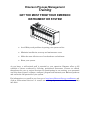
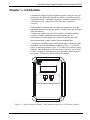
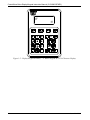
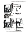
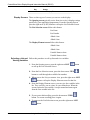
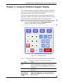
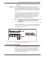
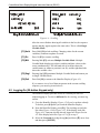
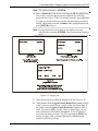
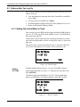
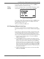
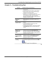
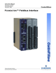
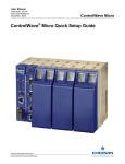
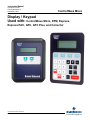
Instruction Manual Document: D5135 Part: D301681X012 November, 2010 ControlWave Micro Display / Keypad Used with: ControlWave Micro, EFM, Express, Express PAC, GFC, GFC Plus, and Corrector Remote Automation Solutions www.EmersonProcess.com/Remote IMPORTANT! READ INSTRUCTIONS BEFORE STARTING! Be sure that these instructions are carefully read and understood before any operation is attempted. Improper use of this device in some applications may result in damage or injury. The user is urged to keep this book filed in a convenient location for future reference. These instructions may not cover all details or variations in equipment or cover every possible situation to be met in connection with installation, operation or maintenance. Should problems arise that are not covered sufficiently in the text, the purchaser is advised to contact Emerson Process Management, Remote Automation Solutions division (RAS) for further information. EQUIPMENT APPLICATION WARNING The customer should note that a failure of this instrument or system, for whatever reason, may leave an operating process without protection. Depending upon the application, this could result in possible damage to property or injury to persons. It is suggested that the purchaser review the need for additional backup equipment or provide alternate means of protection such as alarm devices, output limiting, fail-safe valves, relief valves, emergency shutoffs, emergency switches, etc. If additional information is required, the purchaser is advised to contact RAS. RETURNED EQUIPMENT WARNING When returning any equipment to RAS for repairs or evaluation, please note the following: The party sending such materials is responsible to ensure that the materials returned to RAS are clean to safe levels, as such levels are defined and/or determined by applicable federal, state and/or local law regulations or codes. Such party agrees to indemnify RAS and save RAS harmless from any liability or damage which RAS may incur or suffer due to such party's failure to so act. ELECTRICAL GROUNDING Metal enclosures and exposed metal parts of electrical instruments must be grounded in accordance with OSHA rules and regulations pertaining to "Design Safety Standards for Electrical Systems," 29 CFR, Part 1910, Subpart S, dated: April 16, 1981 (OSHA rulings are in agreement with the National Electrical Code). The grounding requirement is also applicable to mechanical or pneumatic instruments that include electrically operated devices such as lights, switches, relays, alarms, or chart drives. EQUIPMENT DAMAGE FROM ELECTROSTATIC DISCHARGE VOLTAGE This product contains sensitive electronic components that can be damaged by exposure to an electrostatic discharge (ESD) voltage. Depending on the magnitude and duration of the ESD, this can result in erratic operation or complete failure of the equipment. Read supplemental document S14006 for proper care and handling of ESD-sensitive components. Remote Automation Solutions A Division of Emerson Process Management 1100 Buckingham Street, Watertown, CT 06795 Telephone (860) 945-2200 Emerson Process Management Training GET THE MOST FROM YOUR EMERSON INSTRUMENT OR SYSTEM Avoid Delays and problems in getting your system on-line Minimize installation, start-up and maintenance costs. Make the most effective use of our hardware and software. Know your system. As you know, a well-trained staff is essential to your operation. Emerson offers a full schedule of classes conducted by full-time, professional instructors. Classes are offered throughout the year at various locations. By participating in our training, your personnel can learn how to install, calibrate, configure, program and maintain your Emerson products and realize the full potential of your system. For information or to enroll in any class, go to http://www.EmersonProcess.com/Remote and click on “Educational Services” or contact our training department in Watertown at (860) 945-2200. This page is intentionally left blank ControlWave Micro Display/Keypad Manual (D5135) Contents Chapter 1 – Introduction 1-1 Chapter 2 – Installation & Configuration 2-1 2.1 Configuring Your Application to Work with the Display/Keypad ...............................................2-1 Chapter 3 – Using the Dual-Button Keypad / Display 3-1 Chapter 4 – Using the 25-Button Keypad / Display 4-1 4.1 4.2 4.3 Scrolling (25-button keypad) .....................................................................................................4-3 Logging-On (25-button Keypad only)........................................................................................4-4 Options after You Log On .........................................................................................................4-6 4.3.1 Setting the ControlWave’s Clock ..................................................................................4-6 4.3.2 Choosing a Different List to View..................................................................................4-7 4.3.3 Activating Scrolling for the Selected List.......................................................................4-8 4.3.4 Moving Through a Variable List Manually.....................................................................4-8 4.3.5 Changing Variables.......................................................................................................4-8 4.3.6 Logging-Off .................................................................................................................4-11 Chapter 5 – Troubleshooting Tips Issue Nov-2010 5-1 Contents v This page is intentionally left blank ControlWave Micro Display/Keypad Instruction Manual (D5135) Chapter 1 – Introduction ControlWave Display/Keypad assemblies provide a built-in, local, user interface for the following ControlWave models: ControlWave Micro, ControlWave EFM, ControlWave Express, ControlWave Express PAC, ControlWave GFC, ControlWave GFC Plus, and ControlWave Corrector. These optional assemblies allow an operator or engineer to view and, depending upon the keypad type, modify, variable values and associated status information. Variables can include inputs, process variables, calculated variables, constants, setpoints, tuning parameters and outputs used in a measurement or control application. Status bits include alarm state, alarm acknowledge, control, manual, and questionable data. ControlWave controllers support two different types of display/keypad assemblies; one with a dual-button keypad (see Figure 1-1), and one with a 25-button keypad (see Figure 1-2). Each key has positive tactile feedback. This means that as you firmly depress the keys, you will feel it click as it engages. Both display/keypad assemblies utilize identical four-line by 20 character liquid crystal (LCD) displays. Figure 1-1.- Display/Keypad Assembly – Dual-Button Keypad & 4 X 20 Character Display Issue Nov-2010 Introduction 1-1 ControlWave Micro Display/Keypad Instruction Manual (CI-CWM-DSPKEY) Figure 1-2.- Display/Keypad Assembly – 25 Button Keypad & 4 X 20 Character Display 1-2 Introduction Issue Nov-2010 ControlWave Micro Display/Keypad Instruction Manual (D5135) Chapter 2 – Installation & Configuration Caution To ensure safe use of this product, please review and follow the instructions in the following supplemental documentation: WARNING Supplement Guide - ControlWave Site Considerations for Equipment Installation, Grounding, and Wiring (S1400CW) ESDS Manual – Care and Handling of PC Boards and ESD Sensitive Components (S14006) EXPLOSION HAZARD When the ControlWave-series controller is situated in a hazardous location, turn off power before servicing or replacing the unit and before installing or removing wiring. Do not connect or disconnect equipment unless the power is switched off or the area is known to be non-hazardous. In most cases, the display/keypad assembly arrives factory-installed in the enclosure. If you purchase the display/keypad assembly separately, and want to install it yourself, follow the installation drawings. See Figure 2-1 for the dual-button keypad, and Figure 2-2 for the 25-button keypad. Once you’ve installed the display/keypad assembly, connect the display cable between the RJ-45 jack (J1) on the display/keypad assembly and the RJ-45 display interface jack on the controller. 2.1 Configuring Your Application to Work with the Display/Keypad You configure the Display/Keypad in ControlWave Designer by adding the DISPLAY function block to your project, and configuring its parameters. The amount of configuration required varies depending upon the type of keypad (25-button or dual-button) and the operating mode you choose. See the DISPLAY function block online help pages in ControlWave Designer for instructions. Issue Nov-2010 Installation & Configuration 2-1 ControlWave Micro Display/Keypad Instruction Manual (D5135) Figure 2-1. Dual-Button Display/Keypad Assembly Installation Drawing 2-2 Installation & Configuration Issue Nov-2010 ControlWave Micro Display/Keypad Instruction Manual (D5135) 10 1 5.50 5.50 3.25 3.13 .19 1.13 .313 .31 TYP 1.25 .75 2.750 .43 7.38 .06 2.13 2.00 .25 MAX TYP. .25 1.25 4.19 .06 6.500 .50 .75 10 .190 .170 4.69 7.38 1 3.625 .937 Figure 2-2. 25-Button Display/Keypad Assembly Installation Drawing Issue Nov-2010 Installation & Configuration 2-3 This page is intentionally left blank ControlWave Micro Display/Keypad Instruction Manual (D5135) Chapter 3 – Using the Dual-Button Keypad / Display The dual-button display/keypad shows variable information through a series of lists. The dual-button display/keypad does not support changing variable values or status information; for that, you must have the 25-button keypad. From an opening screen, you enter a list selection screen to select the list you want to view, and then the display scrolls through the variables in the list, one at a time, at a user-defined rate so you can view variable values and status information. If there is no keypad activity for a certain period of time, scrolling stops and the display shuts off to conserve power until you press any key. When you press a key after the timeout the display returns to the opening screen. Note: Your application programmer can specify the length of time before scrolling stops through the iiDisplayBlankTime parameter in the DISPLAY function block. Dual-Button The two buttons available are the down-arrow (ITEM) and right-arrow Keypad (LIST) buttons. Table 3-1 describes the function of these buttons. Figure 3-1. Dual-Button Keypad Table 3-1. Dual-Button Keypad Functions Key ITEM LIST Issue Nov-2010 Usage Press this to: Go through the list of available lists. Start/Stop scrolling of the currently selected list. Press this to: Go from the Opening screen to the List Selection screen. Choose the current list on the List Selection screen for viewing. This calls up the Display Element screen (which shows the variables in the chosen list). Go back to the List Selection screen from the Using the Dual-Button Display/Keypad 3-1 ControlWave Micro Display/Keypad Instruction Manual (D5135) Key Usage Display Element screen. Display Screens There are three types of screens you can see on the display: The Opening screen typically varies from site to site; it displays strings specified by your application programmer. From the Opening Screen, press the right arrow (LIST) button to call up the List Selection Screen. The List Selection screen follows this format: List Name List Number <Blank Line> <Blank Line> The Display Element screen follows this format: <Blank Line> <Blank Line> Variable Name or data Variable Name or data Selecting a List and Follow this procedure to call up lists and view variables. Viewing Variables 1. From the Opening screen, press the right arrow LIST button to call up the List Selection Screen. 2. From the List Selection screen, press the down arrow ITEM button to scroll through the available list numbers. 3. When you see the List you want to view, press the right arrow LIST button to call up the Display Element screen for that list. 4. From the Display Element screen, you can view the variables in the list. They scroll by, one at a time, at a pre-defined rate. When the screen reaches the last variable, it wraps-around and starts again from the first variable in the list. 5. If you want to halt scrolling, press the down arrow ITEM button. To resume scrolling press it again. 6. To return to the List Selection screen, press the right arrow LIST button. 3-2 Using the Dual-button Display/Keypad Issue Nov-2010 ControlWave Micro Display/Keypad Instruction Manual (D5135) Chapter 4 – Using the 25-Button Keypad / Display The 25-button display/keypad shows variable information through a series of lists. If you have sufficient security privileges, you can view and modify variable values or status information. If there is no keypad activity for a certain period of time the display shuts off to conserve power until you press any key. When you press a key after the timeout the display returns to the opening screen. Note: Your application programmer can specify the length of time before scrolling stops through the iiDisplayBlankTime parameter in the DISPLAY function block. Figure 4-1. 25 Button Keypad Table 4-1 outlines the function of the different buttons on the keypad. Table 4-1. 25-Button Keypad Key Descriptions Key [F1], [F2], [F3], [F4] [INIT] [0/OFF], [1/ON], [2], [3], [4], [5], [6], [7], [8], [9], [-], [] Issue Nov-2010 Usage These function keys take on a variety of different functions depending on the situation. The function of these keys appears on the legend line (bottom line) of the display. The INIT key is used to terminate the keyboard session and log off. Use the number, decimal point, and minus sign keys to enter a new analog value. For logical variables the [0/OFF] and [1/ON] keys let you change the state of logical variables. Using the 25-button Display/Keypad 4-1 ControlWave Micro Display/Keypad Instruction Manual (D5135) Key [▲] [▼] [ALM I/E] [ALM ACK] [A/M] [OPER I/E] [DEL] [ENTER] Usage Each press of this key raises an analog variable value by 1% of the displayed value or turns a logical variable ON. Each press of this key lowers an analog variable value by 1% of the displayed value or turns a logical variable OFF. Use this key to enable or inhibit alarm variable reporting. Use this key to acknowledge alarms. Toggle between AUTO (CE) and MANUAL (CI) with this key. Toggle between manual inhibit (MI) and enable (ME) with this key. Use this key to erase digits that you enter on the keypad. Use this key ito enter new data from the display into the controller, e.g., password or variable values. Identifier Display The first display that shows on the screen is the Identifier Display. (See Figure 4-2.) Figure 4-2. Identifier Display The Identifier Display is the starting point from which you can go to other displays. It shows an identification message and the words Login and Scroll at the bottom of the screen. The identification message varies depending upon configuration entries made in the DISPLAY function block; it might contain the name of the controller, the plant equipment it monitors, or other information. Notes: 4-2 If your display shows something else, press the [F4] key until you see the words Login and Scroll on the bottom line. If your screen is blank, turn the brightness screw clockwise. This screw is located to the left of the Keypad (looking at the rear of the 25-Button Display/Keypad Assembly, see Figure 2-2). If no letters Using the 25-button Display/Keypad Issue Nov-2010 ControlWave Micro Display/Keypad Instruction Manual (D5135) appear, the controller has not been programmed properly to operate the keypad. Legend Line The words Login and Scroll at the bottom of the screen are on the legend line. Depending upon which screen is active, the function keys (that is, key [F1] through [F4]) do different things. The legend line tells you which function keys are active and their purpose for that particular screen. Up to four legends can appear on the legend line. The legend on the far left corresponds to the current function of the [F1] key. The current assignment for the [F4] key is on the far right. The current use for keys [F2] and [F3] are described to the left and right of center. When no legend appears, that function key is not active on this screen. For example, in Figure 4-2 only [F1] and [F2] are active. Note: The application programmer can change the legends shown in this manual, so you may not always see the default legends shown. From the Identifier Display, you have two choices. Pressing [F1] allows you to log-on if you have a password. Pressing [F2] activates automatic scrolling through a list of variables. Figure 4-3. Identifier Display Legends and Corresponding Keypad Alignment for 25 Button Membrane Key Matrix Keypad System 4.1 Scrolling (25-button keypad) To begin automatic scrolling, press [F2] from the Identifier Display (Figure 4-2). Variable information appears on the screen and remains there for a period of seconds set by the application programmer. The variable name appears on the first line. The variable value appears on the second line and status information appears on the third line. See Figure 4-4 for an example of this. Issue Nov-2010 Using the 25-button Display/Keypad 4-3 ControlWave Micro Display/Keypad Instruction Manual (D5135) Figure 4-4. - Scrolling After the screen finishes showing all variables in the list, the sequence repeats and they appear again in the same order. This is called Single Variable Mode. [F1] Hold Press Hold [F1] to halt scrolling. Changing values for the current variable(s) continue to update on screen. [F1] Go Press Go [F1] to resume scrolling. [F2] Mlti Pressing Mlti [F2] activates Multiple Variable Mode. Multiple Variable Mode displays up to three variables and their values on the screen simultaneously. The left hand side of each line shows the variable name (or whatever portion it can fit), and the right hand side shows the variable value. [F2] Sngl Pressing Sngl [F2] terminates Multiple Variable Mode and returns you to Single Variable Mode. [F4] Exit Press Exit [F4] to return to the Identifier Display (Figure 4-2). If you want to view a list of data not present in the current scrolling sequence, you must log in and select it. 4.2 Logging-On (25-button Keypad only) The Identifier Display provides access to a list that you can view without logging in. To select a different list for viewing, you must log on first. 1. Go to the Identifier Display (Figure 4-2) if you’re not there already. To do this, press [F4] until you reach the Identifier Display. 2. From the Identifier Display press [F1]. The resulting screen looks like either Figure 4-5A or Figure 4-5C. If the display looks like Figure 4-5C, someone else has already logged on. Skip to Section 4.3. If the display looks like Figure 4-5A, go to step 3. 3. Select the Username by using the up [▲] and down [▼] arrow keys and then press [ENTER]. 4-4 Using the 25-button Display/Keypad Issue Nov-2010 ControlWave Micro Display/Keypad Instruction Manual (D5135) Note: The default username is SYSTEM. 4. Enter a Password for the chosen user using the [0] through [9] keys. For security, asterisks appear instead of digits as you enter the password. (See Figure 4-5B.) If you make a mistake, press [F1] and try again (or use the delete key to delete the previously pressed key action). The default password is 666666. After typing the password, press [ENTER] to log on. Note: If your password is not recognized, the display erases the asterisks after you press [ENTER]. Check your password and try again. Figure 4-5. Logging On 5. Once you log on successfully the display looks like Figure 4-5C. 6. Issue Nov-2010 If the display shows Logged On with Read/Write Access on lines 1 and 2, you can read and write variable values and status flags. If the display shows Logged On with Read Only Access on lines 1 and 2, you cannot change variable values or status flags; you are only permitted to read variable information. To log on again as a user with read/write privileges, log off by pressing the [INIT] key, and log on again, with a username/password combination that supports read/write privileges. Using the 25-button Display/Keypad 4-5 ControlWave Micro Display/Keypad Instruction Manual (D5135) 4.3 Options after You Log On Once you successfully log on, the legend line shows that you have four options. You can: View and change the time and date of the ControlWave controller’s clock. (Clk) Call up a menu of available lists. (Menu) Scroll through an existing list and view data. (Scrl) See Section 4.1. Return to the Identifier Display. (Exit) 4.3.1 Setting the ControlWave’s Clock Once you log on, press [F1] from the logged on display (Clk legend in Figure 4-5C). This opens the Clock Display (Figure 4-6) which shows the current time and date. Today's date is shown in the first line in the format mm/dd/yyyy where mm is the two-digit month, dd is the two-digit day, and yyyy is the fourdigit year. The current time is shown in the form hh:mm:ss where hh is the hour (0-23), mm is the minute (0 to 59) and ss is the second (0 to 59). Figure 4-6. Clock Display Setting the Time From the display shown in Figure 4-6, press Time [F2]. Colons (:) appear on the third line see Figure 4-7. Enter the new time there and press [ENTER]. Valid times range from 00:00:00 to 23:59:59. The keypad/display ignores invalid entries. The display updates to show the new time. Figure 4-7. - Time Set Display 4-6 Using the 25-button Display/Keypad Issue Nov-2010 ControlWave Micro Display/Keypad Instruction Manual (D5135) If you make a mistake while entering the new time, use [DEL] to backspace and delete one character at a time. Setting the Date From the clock display (Figure 4-6) press [F1]. Slash marks (/) appear on the third line. Enter the new date there and press [ENTER]. Figure 4-8. Date Set Display If you make a mistake while entering the new date, use [DEL] to back space and delete one character at a time. Press [F4] to return to the Logged-On Display (Figure 4-5C). When you're finished, press [F4] to exit. 4.3.2 Choosing a Different List to View In Section 4.1 we discussed how to scroll through a list of variables from the Initial Display. You can view those variables without logging on. If you want to see a different list of variables, you need to log on, and activate the Menu function from the Logged-on Display (see Figure 45C). The List Menu shows other groups of variables which you can choose to read. This information is more detailed than in the Scroll List. 1. From the Logged-on Display (Figure 4-5C) press the [F2] key (Menu in the legend line). 2. The List Choice field on the second line of the display shows the number of the first list. If the list has a name, the name shows on the first line. If you want to choose a different list, press the [F2] key (Next in legend line) to move through the numbers of the available lists. To move backwards through the list numbers, use the [F1] key (Prev in legend line). You can also use the up [▲] and down [▼] arrow keys to scroll through the various lists. To move directly to a list, enter the list number. 3. When the number of the list you want to view shows next to List Choice, press [ENTER]. Issue Nov-2010 Using the 25-button Display/Keypad 4-7 ControlWave Micro Display/Keypad Instruction Manual (D5135) Figure 4-9. Using the List Menu Display 4.3.3 Activating Scrolling for the Selected List To activate scrolling after you’ve selected a list, press [F3] (Scrl in legend line.) 4.3.4 Moving Through a Variable List Manually After you select a list and press [ENTER] the display shows the currently Selected List and the first variable in the list. If you only want to view variables, press [F1] (Read in legend line). If you want to change variable values, press [F2] (Write in legend line). Once you’ve chosen read or write, you can move through the list to see additional variables. Press [F2] (Next in legend line) to view the next variable in the list. You can also do this by pressing the down [▼] arrow key. Press [F1] (Prev in legend line) to view the previous variable in the list. You can also do this by pressing the up [▲] arrow key. Automatic wraparound occurs in either direction. When you reach the end of the list, [F1] displays the first variable again. At the top of the list, [F2] displays the last variable of the list. 4.3.5 Changing Variables From Figure 4-9, you can change variable values by pressing [F2] (Write in legend line). Note: 4-8 If your display (Figure 4-9) does not contain Write in the legend line, your password will only allow you to read variables. If you want to change variable values, you must first Using the 25-button Display/Keypad Issue Nov-2010 ControlWave Micro Display/Keypad Instruction Manual (D5135) log-off and then log-on with a username and password combination that allows write privileges. Figure 4-10 shows a sample screen. Refer to Table 4-2 for a description of what the different fields mean. Questionable Data Status Variable Inhibit/Enable Status Alarm Inhibit/ Enable Status Variable Value Variable Name ! Show Previous Variable in list Show Next Variable in list Show 3 variables on screen at the same time Unacknowledged Alarm Alarm Type Exit this screen Figure 4-10. Interpreting Variable Information Table 4-2. Screen Field Descriptions Display Component Description Variable Name The variable name, for example, @GV.FLOW_RATE. Variable Value The value, which could be an analog value, a string value, or a logical state (True/False) or (On/Off). Analog values are displayed in floating point format, for example, 0.0125, 99.627, and 1287.66. When the display cannot show the value in floating point format, scientific format is used (1.287668E+10 or 1.25E-02). CE (Control Enable) means logic in the ControlWave project (application) can update this variable. Variable Inhibit Status CI (Control Inhibit) means logic in the ControlWave project (application) cannot update this variable. ME (Manual Enable) means an operator can update this variable. MI (Manual Inhibit) means an operator cannot update this variable. Note: The application programmer is responsible for implementing variable inhibit/enable logic through appropriate function blocks for this to operate. Alarm Inhibit / Enable Status Issue Nov-2010 Shows only if this is an alarm variable. AE - variable is alarm enabled (alarm changes are reported.) Using the 25-button Display/Keypad 4-9 ControlWave Micro Display/Keypad Instruction Manual (D5135) Display Component Description AI - variable is alarm inhibited (alarm changes are not transmitted.) Alarm State Questionable Data Status Note: The application programmer is responsible for implementing alarm inhibit/enable logic through appropriate function blocks for this to operate. For Analog Variables For Logical Variables HH High-High alarm TA alarm on TRUE HI High alarm FA alarm on FALSE LO Low alarm CA alarm on change of state LL Low Low alarm ! Unacknowledged ! Unacknowledged alarm alarm If data is valid, is blank. If data is questionable, shows a question mark “?” You can perform the following operations on variables: Activating Manual Enable (ME) Mode Before you make any changes, first check the variable inhibit status field. When the display shows ME (manual enable) you can change the variable value or inhibit status. When it shows MI (manual inhibit), you cannot alter the variable value or inhibit status without first changing it to manual enable. To switch to manual enable, press the [OPER I/E] key to change it to ME. Note: Changing the value of an Analog Variable The application programmer is responsible for implementing variable inhibit/enable logic through appropriate function blocks for this to operate properly. Press [F3] (Chng in the legend line) to clear the third line. Use the number keys 0 through 9 to enter the new value. The minus sign and period are also permitted. Press [ENTER]. If you make a mistake, press [F3] (Chng in the legend line) and enter the number again or use the [DEL] key to erase a character. Another way you can enter new values is by using the up [▲] and down [▼] arrow keys. These keys raise and lower the value by 1% of the displayed amount. 4-10 Using the 25-button Display/Keypad Issue Nov-2010 ControlWave Micro Display/Keypad Instruction Manual (D5135) Press [F3] (CHNG in the legend line) then press the [0/OFF] or [1/ON] Changing the state of a button and press [ENTER] to change the state of the logical variable. Logical Variable You can also press the [▲] or down [▼] arrow key to change the state. Acknowledging an Alarm Press [ALM ACK]. Inhibiting / Enabling Alarm Reporting for a Variable Press [ALM I/E] to inhibit or enable alarm reporting for a variable. Alarm detection still occurs, but alarm messages are not transmitted. Note: The application programmer is responsible for implementing alarm inhibit/enable logic through appropriate function blocks for this to operate properly. 4.3.6 Logging-Off Once you log on, you can use the [INIT] key at any time to log-off. When you press this key, the screen looks like Figure 4-11. Press Yes [F1] to log off. You are logged-off when the Identifier Display (Figure 4-2) appears. If you do not want to log-off, press Exit [F4] to leave the Log-Off screen. Note: The system logs you off automatically after a pre-defined period of keyboard inactivity. The application programmer sets the length of this period. Figure 4-11. Log-Off Display Issue Nov-2010 Using the 25-button Display/Keypad 4-11 This page is intentionally left blank ControlWave Micro Display/Keypad Instruction Manual (D5135) Chapter 5 – Troubleshooting Tips Problem Display is blank Display is too dim (or too bright) Possible Cause(s) and Solution(s): No keypad activity – timeout period has expired. Press any key. Controller is powered off. Power on the controller. Display interface cable is disconnected from the controller. Re-connect the cable. Application is not configured to support the display/keypad. Configure DISPLAY function block in your ControlWave project. (See ControlWave Designer online help for DISPLAY function block for information on how to do this.) Display brightness is out of adjustment. Adjust display brightness screw shown in Figure 2-1 or Figure 2-2. Cannot change variable values Wrong type of keypad. You must have 25-button keypad. Insufficient privileges. You must log on with read/write security privileges. Variable is manual inhibited – “MI” shows on display. Press [OPER I/E] button to manually enable the variable. Keypad inactivity timeout is too short (or too long) Inactivity timeout configured incorrectly. Re-configure DISPLAY function block iiDisplayBlankTime parameter to appropriate value. (See ControlWave Designer online help for DISPLAY function block for information on how to do this.) Scroll time configured incorrectly. Re-configure DISPLAY function block iiScrollTime parameter to appropriate value. (See ControlWave Designer online help for DISPLAY function block for information on how to do this.) Scrolling is in HOLD mode. To resume scrolling: For dual button keypad, press the down arrow ITEM Automatic scroll time for variables is too fast (or too slow). Values not scrolling button. For 25-button keypad: Press the [F1] button. Issue Nov-2010 Troubleshooting Tips 5-1 ControlWave Micro Display/Keypad Instruction Manual D5135 November, 2010 NOTICE Emerson Process Management Remote Automation Solutions 1100 Buckingham Street Watertown, CT 06795 Phone: +1 (860) 945-2262 Fax: +1 (860) 945-2525 www.EmersonProcess.com/Remote Emerson Process Management Remote Automation Solutions 6338 Viscount Rd. Mississauga, Ont. L4V 1H3 Canada Phone: 905-362-0880 Fax: 905-362-0882 www.EmersonProcess.com/Remote Emerson Process Management SA de CV Calle 10 #145 Col. San Pedro de los Pinos 01180 Mexico, D.F. Mexico T +52 (55) 5809-5300 F +52 (55) 2614-8663 www.EmersonProcess.com/Remote Emerson Process Management, Ltd. Remote Automation Solutions Blackpole Road Worcester, WR3 8YB United Kingdom Phone: +44 1905 856950 Fax: +44 1905 856969 www.EmersonProcess.com/Remote Emerson Process Management AP Pte Ltd. Remote Automation Solutions Division 1 Pandan Crescent Singapore 128461 Phone: +65-6770-8584 Fax: +65-6891-7841 www.EmersonProcess.com/Remote “Remote Automation Solutions (“RAS”), division of Emerson Process Management shall not be liable for technical or editorial errors in this manual or omissions from this manual. RAS MAKES NO WARRANTIES, EXPRESSED OR IMPLIED, INCLUDING THE IMPLIED WARRANTIES OF MERCHANTABILITY AND FITNESS FOR A PARTICULAR PURPOSE WITH RESPECT TO THIS MANUAL AND, IN NO EVENT SHALL RAS BE LIABLE FOR ANY INCIDENTAL, PUNITIVE, SPECIAL OR CONSEQUENTIAL DAMAGES INCLUDING, BUT NOT LIMITED TO, LOSS OF PRODUCTION, LOSS OF PROFITS, LOSS OF REVENUE OR USE AND COSTS INCURRED INCLUDING WITHOUT LIMITATION FOR CAPITAL, FUEL AND POWER, AND CLAIMS OF THIRD PARTIES. Bristol, Inc., Bristol Babcock Ltd, Bristol Canada, BBI SA de CV and the Flow Computer Division are wholly owned subsidiaries of Emerson Electric Co. doing business as Remote Automation Solutions (“RAS”), a division of Emerson Process Management. FloBoss, ROCLINK, Bristol, Bristol Babcock, ControlWave, TeleFlow and Helicoid are trademarks of RAS. AMS, PlantWeb and the PlantWeb logo are marks of Emerson Electric Co. The Emerson logo is a trademark and service mark of the Emerson Electric Co. All other trademarks are property of their respective owners. The contents of this publication are presented for informational purposes only. While every effort has been made to ensure informational accuracy, they are not to be construed as warranties or guarantees, express or implied, regarding the products or services described herein or their use or applicability. RAS reserves the right to modify or improve the designs or specifications of such products at any time without notice. All sales are governed by RAS’ terms and conditions which are available upon request. © 2010 Remote Automation Solutions, division of Emerson Process Management. All rights reserved.