1
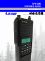
GPH-CMD
PORTABLE RADIO
Service Manual
TABLE OF CONTENTS
SECTION I
GENERAL INFORMATION
1.1
1.2
1.3
INTRODUCTION .......................................................................................................................... 1-1
DESCRIPTION ............................................................................................................................. 1-1
TECHNICAL CHARACTERISTICS .............................................................................................. 1-2
ACCESSORIES ..................................................................................................................... 1-3
LICENSE REQUIREMENTS.................................................................................................. 1-3
SERVICE INFORMATION ..................................................................................................... 1-3
SECTION II
INSTALLATION AND PROGRAMMING
2.1
2.1.1
2.1.2
2.1.3
2.2
2.2.1
2.2.2
2.3
2.4
GENERAL INFORMATION .......................................................................................................... 2-1
UNPACKING AND INSPECTING EQUIPMENT ................................................................... 2-1
BATTERY INSTALLATION.................................................................................................... 2-1
ANTENNA INSTALLATION ................................................................................................... 2-1
HOW TO PROGRAM RADIOS .................................................................................................... 2-2
KEYPAD PROGRAMMING ................................................................................................... 2-2
2.2.1.1 NAVIGATION......................................................................................................... 2-3
2.2.1.2 GROUP PARAMETERS (CH 00) .......................................................................... 2-4
2.2.1.2.1
GROUP OPTIONS: 1-12345678........................................................... 2-4
2.2.1.2.2
GROUP LABEL ..................................................................................... 2-4
2.2.1.3 CHANNEL PARAMETERS (CH 01 – CH 20)........................................................ 2-5
2.2.1.3.1
CHANNEL BANDWIDTH ...................................................................... 2-5
2.2.1.3.2
RECEIVE FREQUENCY ....................................................................... 2-5
2.2.1.3.3
RECEIVE GUARD................................................................................. 2-5
2.2.1.3.4
TRANSMIT FREQUENCY .................................................................... 2-6
2.2.1.3.5
TRANSMIT GUARD .............................................................................. 2-6
2.2.1.3.6
CHANNEL LABEL ................................................................................. 2-6
2.2.1.4 GLOBAL PARAMETERS (GRP 00) ...................................................................... 2-7
2.2.1.4.1
KEYPAD PROGRAMMING PASSWORD............................................. 2-7
2.2.1.4.2
GLOBAL OPTIONS ONE: 1-12345678................................................. 2-7
2.2.1.4.3
GLOBAL OPTIONS TWO: 2-12345678 ................................................ 2-9
2.2.1.4.4
AUTOMATIC NUMERIC IDENTIFICATION (ANI) .............................. 2-10
2.2.1.4.5
TRANSMITTER TIME-OUT TIMER .................................................... 2-10
2.2.1.4.6
SCAN DELAY TIME ............................................................................ 2-11
2.2.1.4.7
BACKLIGHT DURATION .................................................................... 2-11
2.2.1.4.8
PRIORITY 1 CHANNEL ...................................................................... 2-11
2.2.1.4.9
PRIORITY 1 GROUP .......................................................................... 2-12
2.2.1.4.10
PRIORITY 2 CHANNEL ...................................................................... 2-12
2.2.1.4.11
PRIORITY 2 GROUP .......................................................................... 2-12
2.2.1.4.12
OLD-STYLE BK PRIORITY SCAN...................................................... 2-13
2.2.1.4.13
REVIEW GLOBAL PARAMETERS (GRP 00)..................................... 2-13
2.2.1.5 EXIT PROGRAMMING MODE............................................................................ 2-13
CLONING RADIO SETTINGS ............................................................................................. 2-13
TONE CODE GUARD VALUES ................................................................................................. 2-16
DIGITAL CODE GUARD VALUES............................................................................................. 2-16
Specifications are subject to change without notice.
BK RADIO
Page i
General Information
GPH-CMD VHF Radio
SECTION III
OPERATION
3.1
3.1.1
3.2
3.2.1
3.2.2
3.2.3
3.2.4
3.2.5
3.3
3.4
3.5
3.5.1
3.5.2
3.6
3.6.1
3.6.2
3.7
3.7.1
3.7.2
3.7.3
3.8
3.8.1
3.9
3.9.1
3.10
3.10.1
3.10.2
3.10.3
3.10.4
3.10.5
3.10.6
3.11
3.11.1
3.11.2
3.11.3
3.11.4
3.11.5
3.11.6
3.12
3.13
3.13.1
3.13.2
3.13.3
3.13.4
3.13.5
3.13.6
INTRODUCTION .......................................................................................................................... 3-1
FEATURES ............................................................................................................................ 3-1
FCC REQUIREMENTS ................................................................................................................ 3-1
RF ENERGY EXPOSURE AWARENESS & CONTROL INFORMATION, AND
OPERATIONAL INSTRUCTIONS FOR FCC OCCUPATIONAL USE REQUIREMENTS .... 3-2
FEDERAL COMMUNICATIONS COMMISSION REGULATIONS ........................................ 3-2
COMPLIANCE WITH RF EXPOSURE STANDARDS........................................................... 3-3
INDUSTRY CANADA COMPLIANCE.................................................................................... 3-3
RF EXPOSURE COMPLIANCE & CONTROL GUIDELINES AND OPERATING
INSTRUCTIONS .................................................................................................................... 3-3
SAFETY PRECAUTIONS............................................................................................................. 3-4
RADIO CONTROLS ..................................................................................................................... 3-5
BASIC OPERATION..................................................................................................................... 3-6
RECEIVE ............................................................................................................................... 3-6
TRANSMIT............................................................................................................................. 3-6
CODE GUARD OPERATION ....................................................................................................... 3-7
CODE GUARD RECEIVE ...................................................................................................... 3-7
CODE GUARD TRANSMIT ................................................................................................... 3-7
COMMAND GROUP .................................................................................................................... 3-7
BUILDING A COMMAND GROUP ........................................................................................ 3-8
OPERATING FROM THE COMMAND GROUP.................................................................... 3-8
MODIFICATION OF THE COMMAND GROUP .................................................................... 3-8
CHANNEL GROUPS.................................................................................................................... 3-9
SELECT A GROUP/CHANNEL ............................................................................................. 3-9
PROGRAMMABLE TOP SWITCHES/FUNCTION MENU ........................................................... 3-9
KEYPAD LOCK.................................................................................................................... 3-10
SCAN OPERATION ................................................................................................................... 3-10
SCAN CODE GUARD CHANNELS ..................................................................................... 3-10
NUISANCE CHANNEL DELETE ......................................................................................... 3-10
TRANSMIT WITH SCAN ON ............................................................................................... 3-11
TALKBACK SCAN ............................................................................................................... 3-11
CHANGE THE SCAN LIST .................................................................................................. 3-11
GROUP SCAN ..................................................................................................................... 3-11
PRIORITY SCAN........................................................................................................................ 3-12
DUAL PRIORITY SCAN....................................................................................................... 3-12
OLD-STYLE BK PRIORITY SCAN ...................................................................................... 3-13
PRIORITY MODE A WITH SCAN........................................................................................ 3-13
PRIORITY MODE B ............................................................................................................. 3-13
3.11.4.1 PRIORITY MODE B WITH SCAN ....................................................................... 3-13
PRIORITY MODE C............................................................................................................. 3-14
3.11.5.1 PRIORITY MODE C WITH SCAN ....................................................................... 3-14
CHANGE THE PRIORITY 1 CHANNEL .............................................................................. 3-14
USER TRANSMIT CODE GUARD............................................................................................. 3-15
OTHER OPERATIONAL FEATURES ........................................................................................ 3-15
SCAN DELAY ...................................................................................................................... 3-15
HI/LO POWER ..................................................................................................................... 3-16
DTMF ENCODING............................................................................................................... 3-16
ANI ENCODING................................................................................................................... 3-16
TIME-OUT TIMER................................................................................................................ 3-16
BUSY CHANNEL ................................................................................................................. 3-16
3.13.6.1 BUSY CHANNEL INDICATION ........................................................................... 3-17
3.13.6.2 BUSY CHANNEL LOCKOUT .............................................................................. 3-17
3.13.6.3 BUSY CHANNEL LOCKOUT WITH OVERRIDE ................................................ 3-17
Specifications are subject to change without notice.
Page ii
BK RADIO
GPH-CMD VHF Radio
General Information
3.14
ALPHANUMERIC DISPLAY....................................................................................................... 3-18
3.14.1
DISPLAY BACKLIGHTING .................................................................................................. 3-19
3.14.2
CHANNEL AND GROUP LABELS ...................................................................................... 3-19
3.15
DEFINITIONS AND ACRONYMS .............................................................................................. 3-20
FIGURE 3-1
LIQUID CRYSTAL DISPLAY......................................................................................... 3-18
SECTION IV
THEORY OF OPERATION
4.1
4.2
4.3
4.3.1
4.3.2
4.3.3
4.3.4
4.3.5
INTRODUCTION .......................................................................................................................... 4-1
DESCRIPTION ............................................................................................................................. 4-1
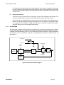
THEORY OF OPERATION .......................................................................................................... 4-1
RECEIVER............................................................................................................................. 4-1
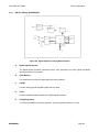
TRANSMITTER...................................................................................................................... 4-3
SYNTHESIZER ...................................................................................................................... 4-5
SYSTEMS AREA ................................................................................................................... 4-7
DIGITAL SIGNAL PROCESSING.......................................................................................... 4-9
FIGURE 4-1
FIGURE 4-2
FIGURE 4-3
FIGURE 4-4
FIGURE 4-5
FIGURE 4-6
RECEIVER BLOCK DIAGRAM ....................................................................................... 4-2
TRANSMITTER BLOCK DIAGRAM................................................................................ 4-3
POWER AMPLIFIER BLOCK DIAGRAM........................................................................ 4-4
ANTENNA SWITCH FUNCTIONAL BLOCK DIAGRAM................................................. 4-4
SYNTHESIZER BLOCK DIAGRAM ................................................................................ 4-5
DIGITAL SIGNAL PROCESSING BLOCK DIAGRAM .................................................... 4-9
SECTION V
MAINTENANCE
5.1
5.2
5.3
5.3.1
5.3.2
5.3.3
5.4
5.4.1
5.4.2
5.4.3
5.5
5.5.1
5.5.2
5.6
INTRODUCTION .......................................................................................................................... 5-1
TEST EQUIPMENT REQUIRED .................................................................................................. 5-1
OVERHAUL .................................................................................................................................. 5-2
ACCESSORIES ..................................................................................................................... 5-2
CLEANING............................................................................................................................. 5-3
REPAIR.................................................................................................................................. 5-4
DISASSEMBLY/ASSEMBLY........................................................................................................ 5-4
BATTERY REMOVAL ............................................................................................................ 5-4
UNIT DISASSEMBLY ............................................................................................................ 5-4
ASSEMBLY............................................................................................................................ 5-5
ALIGNMENT PROCEDURES ...................................................................................................... 5-6
TEST SETUP ......................................................................................................................... 5-6
ALIGNMENT ORDER ............................................................................................................ 5-6
TROUBLESHOOTING ......................................................................................................... 5-15
FIGURE 5-1
FIGURE 5-2
FIGURE 5-3
FIGURE 5-4
TRANSMITTER TEST SETUP...................................................................................... 5-11
SYSTEMS BOARD ADJUSTMENTS............................................................................ 5-12
RECEIVER TEST SETUP ............................................................................................. 5-13
RX/TX BOARD ADJUSTMENTS .................................................................................. 5-14
Specifications are subject to change without notice.
BK RADIO
Page iii
General Information
GPH-CMD VHF Radio
SECTION VI
ILLUSTRATED PARTS LIST
6.1
6.2
6.3
INTRODUCTION .......................................................................................................................... 6-1
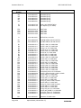
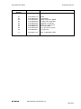
PARTS LIST DESCRIPTION ....................................................................................................... 6-1
ASSEMBLY DRAWING SYMBOLS ............................................................................................. 6-1
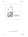
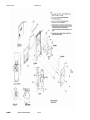
FINAL ASSEMBLY .................................................................................................................................... 6-2
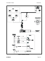
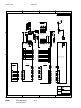
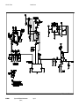
INTERCONNECT DIAGRAM .................................................................................................................... 6-5
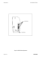
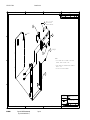
SYSTEM FRAME ASSEMBLY.................................................................................................................. 6-7
CONTROL BOARD (505-662) .......................................................................................................... 6-13
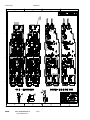
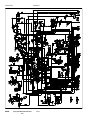
SYSTEMS BOARD (309-610) .......................................................................................................... 6-19
TOP FRAME ASSEMBLY................................................................................................................. 6-33
RX/TX FRAME ASSEMBLY .................................................................................................................... 6-37
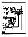
RX/TX BOARD, 5 WATT (309-609).................................................................................................. 6-41
FRONT COVER ASSEMBLY .................................................................................................................. 6-53
OPTIONS BOARD (309-620) ........................................................................................................... 6-57
KEYBOARD/DISPLAY ASSEMBLY ................................................................................................. 6-65
APPENDIX A ............................................................................................................................................. A-1
Specifications are subject to change without notice.
Page iv
BK RADIO
SECTION I
GENERAL INFORMATION
1.1
INTRODUCTION
This manual contains information about the physical, mechanical, and electrical characteristics of
the BK Radio GPH-CMD radios.
1.2
DESCRIPTION
The GPH-CMD radios are self-contained VHF FM Radios covering the frequency range of
136MHz to 174MHz. The radios are multi-channel and digitally synthesized using a single crystal
for frequency control. All models incorporate an EEPROM for the storage of data such as channel
frequencies, Code Guards, and channel labels. All models also include low-battery and busychannel indicators. Toggle switches can be programmed to control hi/low transmit power, channel
scan, priority scan, repeater talk-around, and group scan. Status and channel information is
displayed over a liquid crystal display. Connectors are provided on the side of the unit for an
external antenna, microphone, speaker, and other optional accessories. A variety of twist-off
battery packs are also available.
Specifications are subject to change without notice.
BK RADIO
Page 1-1
General Information
1.3
GPH-CMD VHF Radio
TECHNICAL CHARACTERISTICS
POWER SUPPLY:
One rechargeable nickel-cadmium or nickel-metal-hydride
battery pack with temperature sensor or one alkaline battery
pack
OPERATIONAL FEATURES:
Programmable Switches
Dual Priority Scan
Transmit Time-Out Timer
Scan Delay
Tone Code Guard (CTCSS)
Digital Code Guard (CDCSS)
Nuisance Channel Delete
User Selectable Transmit Code Guard
Frequency Display
User Selectable Scan
Busy Channel Indicate / Lockout
DTMF/ANI Encode
Interstitial Frequency Capability
TalkBack Scan
CHANNELS:
500 (25 groups of 20 channels)
OPERATING TEMPERATURE:
-30° to +60° C
PHYSICAL DIMENSIONS:
Weight:
20 oz. (24 oz. with large battery)
0.6 kilograms (0.7 kg with large battery)
Width:
2.55 in. (64.8 millimeters)
Depth:
1.5 in. (38.1 mm.)
Height:
6.6 in. (167.6 mm.)
7.8 in. (198.1 mm. with large battery)
ANTENNA TYPE:
Helical wound molded rubber flex (standard)
BNC Helical wound molded rubber flex (optional)
CHANNEL SPACING:
15/30 and 12.5/25 kHz
CHANNEL INCREMENTS:
5.0/6.25/7.5 kHz
MAX CURRENT DRAIN:
Transmit 5 Watt:
1.5 amps
Receive:
255 mA
Receive Standby:
100 mA (battery save off)
20 mA (battery save on)
FCC IDENTIFICATION NUMBER:
K95DPHX51
(5/2 Watt Models)
Specifications are subject to change without notice.
Page 1-2
BK RADIO
GPH-CMD VHF Radio
General Information
TRANSMITTER
25 / 30 kHz
12.5 / 15 kHz
RF OUTPUT POWER:
SPURIOUS AND HARMONICS:
MODULATION DEVIATION:
FM HUM AND NOISE:
FREQUENCY STABILITY:
AUDIO DISTORTION:
AUDIO RESPONSE (per EIA):
5/2 Watts
60 dB
5 kHz
50 dB
±2.5 PPM
3%
+1 dB / -3 dB
5/2 Watts
60 dB
2.5 kHz
45 dB
±2.5 PPM
3%
+1 dB / -3 dB
MODULATION CHARACTERISTICS:
16K0F3E
11K0F3E
25 / 30 kHz
12.5 / 15 kHz
RECEIVER
SENSITIVITY: 12dB SINAD
NOISE SQUELCH:
SELECTIVITY:
IMAGE AND SPURIOUS RESPONSES:
INTERMODULATION:
AUDIO RESPONSE (per EIA):
AUDIO OUTPUT (@ 5% Dist.):
0.25µV
0.18µV
72 dB
75 dB
70 dB
+1 dB / -3 dB
500mW
0.25µV
0.18µV
60 dB
75 dB
70 dB
+1 dB / -3 dB
500mW
Accessories
Use only BK Radio approved supplied or replacement antennas, batteries, and accessories. Use
of non-BK Radio approved antennas, batteries, and accessories may exceed the FCC RF
exposure guidelines. For a list of BK Radio approved accessories visit the following website:
http://www.relm.com.
License Requirements
This equipment must be licensed by the Federal Communications Commission (FCC) before it
may be used. Your BK Radio dealer can assist you in filing the appropriate application for the
FCC, and will program each radio with your authorized frequencies and signaling codes.
Service Information
If you need service, contact your local BK Radio dealer equipped to service your radio. If you find
it impractical to have service performed by your local dealer, contact BK Radio at the address
below:
BK Radio
ATTN: Customer Service
7100 Technology Drive
West Melbourne, FL 32904
Voice (800) 422-6281
FAX
(321) 953-7986
Specifications are subject to change without notice.
BK RADIO
Page 1-3
SECTION II
INSTALLATION AND PROGRAMMING
2.1
GENERAL INFORMATION
This section contains information concerning the installation and programming of BK Radio GPHCMD radios.
2.1.1
UNPACKING AND INSPECTING EQUIPMENT
Exercise extreme care when unpacking the equipment. Make a visual inspection of the unit for
evidence of damage incurred during shipment. If a claim for damage is to be made, save the
shipping container to substantiate the claim. The claim should be promptly filed with the
transportation company. It would be advisable to retain the container and packaging material after
all equipment has been removed in the event that equipment storage or reshipment should
become necessary.
2.1.2
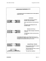
BATTERY INSTALLATION
A. BK Radio battery packs are available in a variety of sizes and types for special applications.
Rechargeable battery packs can be charged separately or while attached to a radio.
NOTE: For safety reasons, rechargeable battery packs are shipped uncharged or only
partially charged. Therefore, a rechargeable battery pack should be properly charged
before use.
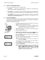
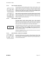
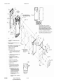
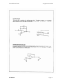
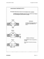
B. To install the battery, locate the center hub on the radio base and place it in the recess of the
battery pack. Position the pack approximately at a 30° offset, seating two metal studs in their
recess. Apply upward pressure to the pack while twisting the pack to its final (in line with the
radio) position. The metal tab will click, locking the pack in position.
C. To remove the battery pack, first turn the radio off. Then, as shown above, push up the metal
tab on the side of the case while twisting the battery pack approximately 30° and remove it
from the radio.
NOTE: All information programmed into the radio is maintained even when the battery pack
is removed.
D. Periodically check the contacts on the battery pack for dirt that may prevent a good electrical
contact with the charging base
WARNING: EXPLOSION HAZARD
Do not drop a battery pack into fire.
An explosion may occur.
2.1.3
ANTENNA INSTALLATION
Insert the flexible helical-wound antenna into the radio's antenna connector and turn it clockwise
until it is firmly seated.
BK RADIO
Page 2-1
Installation and Programming
2.2
GPH-CMD VHF Radio
HOW TO PROGRAM RADIOS
You can program GPH-CMD radios in three different ways:
A. BY KEYPAD
A radio can be programmed with its keypad and a programming plug,
LAA0701. That procedure is described in this section.
B. BY CLONING You can transfer a radio’s programmed settings to another GPH-CMD or
GPH radio by using a cloning cable, LAA0700. See “Cloning Radio Settings" in section 2.2.2.
C. BY COMPUTER With a computer, GPH-CMD programming software and an LAA0725
interface cable. That procedure is not described in this manual. Contact BK Radio for the
programming cable and required software.
2.2.1
KEYPAD PROGRAMMING
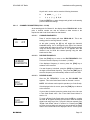
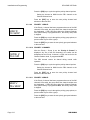
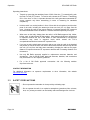
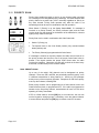
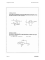
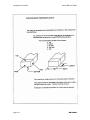
Some radios are shipped with a door covering the keypad and display. Before programming,
remove the door by removing the battery pack, engaging the door just below the speaker grill,
and sliding the door downward. Replace the battery pack.
Make sure the battery pack is charged.
1. Insert the programming plug into the side connector of the radio. The
push-button master switch will be on the top.
Master
Switch
NOTE: The cloning cable can be used as a substitute for the
programming plug by inserting the end with the push-button
master switch into the side connector of the radio.
2. Select a channel group to be programmed. See "Channel Groups" in
section 3.8 of this manual.
3. Press and hold the master switch.
4. While holding the master switch, press and hold the [FCN] key. After
approximately three seconds the LCD will display ’PSWRD-******’.
Programming
Plug
5. Release the [FCN] key and the master switch. The radio is now in
the Password Entry Mode.
PSWRD-******
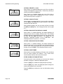
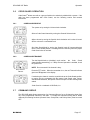
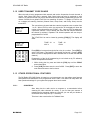
6. Enter the six-digit password code. Without the correct password
code, you cannot proceed with programming.
NOTE: New radios shipped from the factory are assigned the
password code 000000.
If the password code is entered incorrectly, the radio will reset to
normal operation. Try again, starting at step 2.
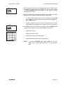
PROG
ch
00
7. Press the [ENT] key to proceed to Programming Mode. The display
will change to ‘PROG CH 00’.
NOTE: Keypad Programming Mode cannot be entered when the
radio is operating in the Command Group. If the display
flashes “CMND GRP” when you try to enter
Programming Mode, release the master switch and
[FCN] key, and select a different group.
Page 2-2
BK RADIO
GPH-CMD VHF Radio
2.2.1.1
Installation and Programming
NAVIGATION
1
2
3
FCN
4
5
6
PRI
7
8
9
ENT
*
0
#
CLR
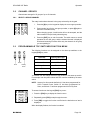
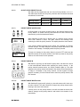
When Programming Mode is entered, programming starts (after password
entry) with the Group Parameters (CH 00) for the currently selected group.
To edit another Channel Group (GRP 01 - 25), press and hold the [#] key at
any CH prompt to get the group selection prompt. Enter the number of the
group to be programmed, or press the [PRI] key to increment to the desired
group. Once the desired group is selected, press [FCN] to access the data.
Press the [FCN] key repeatedly to cycle through the data fields, and then
loop back to the CH 00 entry point.
GROUP PARAMETERS (CH 00) include:
Group Options: 1-12345678 (1-7 = undefined, 8 = group scan list bit)
Group Label
To edit channel data, at the CH 00 prompt enter the number of the channel to
be programmed, or press the [PRI] key to increment to the desired channel.
Press the [FCN] key repeatedly to cycle through the data fields, and then
loop back to the CH entry point.
CHANNEL PARAMETERS (CH 01 - 20) include:
Bandwidth ([#] key at CH prompt toggles Wide/Narrow)
RX Frequency
RX CxCSS
TX Frequency
TX CxCSS
Channel Label
To edit global data (GRP 00), press and hold the [#] key at any CH prompt to
get the group selection prompt. Enter ‘0’ to select global data. Press [FCN]
to access the data. Press the [FCN] key repeatedly to cycle through the data
fields, and then loop back to the GRP 00 entry point.
GLOBAL PARAMETERS (GRP 00) include:
BK RADIO
Keypad Programming Password
Global Options 1: Battery Saver, TX on PRI1, PRI1 Lock, Scan List
Lock, Backlight Triggers, Beep Disable
Global Options 2: Busy Channel Mode, ANI/DTMF Mode
ANI ID
TX Time-Out Timer
Scan Delay
Backlight Duration
Priority 1 Channel
Priority 1 Group: (skipped if Channel = OFF or MAIN)
Priority 2 Channel
Priority 2 Group: (skipped if Channel = OFF or MAIN)
Page 2-3
Installation and Programming
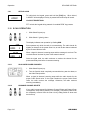
2.2.1.2
GPH-CMD VHF Radio
GROUP PARAMETERS (CH 00)
Press the [FCN] key at the CH 00 prompt to access group parameters.
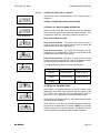
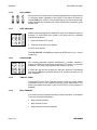
2.2.1.2.1
GROUP OPTIONS: 1-12345678
This is a group of eight individual options that can be enabled or
disabled.
When an option is enabled, the corresponding number in the
display will flash. When the option is disabled the number is
steady. If you wish to change the option from enabled to
disabled or vice versa, press the number key corresponding to
that option.
OPTIONS 1 THROUGH 7
Reserved for future options.
OPTION 8: GROUP SCAN LIST
When Option 8 is enabled (flashing) the current group will be
scanned when the radio is operating in Group Scan Mode.
PROG
1-12345678
GRP OPTIONS
Press the [ENT] key to store the group options settings into
memory and advance to the next field.
Press the [FCN] key to advance to the next field without saving
changes.
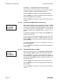
2.2.1.2.2
PROG
LABEL 1
GROUP LABEL
GROUP LABEL
After Group Options, the display will show the label for the
Channel Group. Each Channel Group can have a label of up to
twelve characters or spaces. The characters can include 0-9, AZ, –, -, ., *, +, <, >, /, \, |, $, %, h, or blank.
If no change is needed, press the [FCN] key to go back to the
starting point for Channel 0 settings.
NOTE:
Special software available from BK Radio lets you
enter Group Labels and Channel Labels from a
computer. Contact your dealer for information.
Changing The Group Label
Labels are edited from left to right. Pressing the [PRI] key
moves the cursor to the next character. Pressing and holding
the [PRI] key backspaces to the previous character.
The number keys 2 – 9 allow for entry of the letters printed on
the respective keys. For example, the first press of the [2] key
enters the letter A, the second press enters a B, the third press
enters a C, and the forth press enters a 2. The letters Q and Z
are entered with keys 7 and 9.
Page 2-4
BK RADIO
GPH-CMD VHF Radio
Installation and Programming
Keys 0 and 1 can be used to enter the following characters:
0:
0, space, –, _, ., *, +
1:
1, <, >, /, \, |, $, %, h
Press the [ENT] key to store changes and go back to the starting
point for Channel 0 settings.
2.2.1.3
CHANNEL PARAMETERS (CH 01 – CH 20)
At the starting point for Channel 0, the display shows ‘PROG CH 00’. At this
point, a channel number can now be entered to allow access to the
frequencies and Code Guard values for that channel.
2.2.1.3.1
Press ‘1’ and the display will show ‘PROG CH 01’. This is the
starting point for entering channel 1 values.
PROG
CH
01 N
At this point, pressing the [#] key will toggle the channel's
bandwidth setting. An 'N' will appear to the right of the channel
number when the channel is set for 12.5/15 kHz channel spacing
using the narrow band receiver filter. A ‘W’ appears when the
channel is set for 25/30 kHz channel spacing using the wide
band receiver filter.
2.2.1.3.2
PROG
CHANNEL BANDWIDTH
RECEIVE FREQUENCY
Press the [FCN] key to move to the ‘RX FREQUENCY’ field.
This is the receive frequency for channel 1 (in MHz).
RX
148.00000
rx frequency
If the displayed frequency is correct, press the [FCN] key to
advance to the next field.
If a new frequency is desired, press the [CLR] key followed by
the digits of the desired frequency. Then press the [ENT] key to
store this frequency and automatically advance to the next field.
2.2.1.3.3
PROG
RX
CG
000.0
rx guard
RECEIVE GUARD
After the RX FREQUENCY is set, the ‘RX GUARD’ field
appears. This is the Code Guard value for Channel 1 receive.
NOTE: 0.0 indicates carrier squelch operation (no Code Guard).
If the displayed value is correct, press the [FCN] key to advance
to the next field.
If a new value is desired, press the number keys 0 thru 9 to enter
a Tone Code Guard value. See "Tone Code Guard Values" in
section 2.3.
PROG
RX
D 023
Rx Guard
BK RADIO
CG
To enter a Digital Code Guard value press the [#] key, causing
the letter ‘D’ to appear followed by three zeros. Enter the desired
digital code using keys 0 thru 7 (keys 8 & 9 do not respond). See
"Digital Code Guard Values" in section 2.4. Pressing the [PRI]
key after the three-digit code has been entered allows the digital
code to be inverted. When the displayed value is correct, press
Page 2-5
Installation and Programming
GPH-CMD VHF Radio
the [ENT] key to store the Code Guard value and automatically
advance to the next field.
2.2.1.3.4
TRANSMIT FREQUENCY
After the RX GUARD is set, the ‘TX FREQUENCY’ field appears.
This is the transmitter frequency for Channel 1.
PROG TX
148.00000
Tx frequency
If it is correct, press the [FCN] key to advance to the next field.
If you wish to change it, press the [CLR] key followed by the
frequency in MHz then [ENT] to store the new frequency and
automatically advance to the next field.
Only valid frequencies will be operable.
If you want to operate this channel as a receive-only channel,
press the [CLR] key (setting the display to 0.0) followed by the
[ENT] key. The transmitter will be locked off for this channel.
2.2.1.3.5
PROG TX
After the TX FREQUENCY is set, the ‘TX GUARD’ field appears.
This is the Code Guard value for Channel 1 transmit (0.0
indicates ’no guard’). If this value is correct press the [FCN] key
to advance to the next field. To enter a new value, press the
[CLR] key to reset the display to 0.0. Press the number keys to
enter a Tone Code Guard value. See "Tone Code Guard
Values" in section 2.3.
CG
100.0
Tx Guard
PROG TX
To enter Digital Code Guard, first press the [CLR] key, then the
[#] key, causing the letter ‘D’ to appear followed by three zeros.
Enter the desired digital code using keys 0 thru 7 (keys 8 & 9 do
not respond). See 'Digital Code Guard Values" in section 2.4.
Pressing the [PRI] key after the three digit code has been
entered allows the digital code to be inverted. When the
displayed value is correct, press the [ENT] key to store the Code
Guard and automatically advance to the next field.
CG
D 023
Tx Guard
2.2.1.3.6
PROG TX
Label 18
Chan label
TRANSMIT GUARD
CHANNEL LABEL
After the TX GUARD is set, the ‘CHAN LABEL’ field appears. If
this label is correct press the [FCN] key to proceed to the entry
point.
If a new channel label is desired, follow the instructions under
"Group Label" in section 2.2.1.2.2.
After the CHAN LABEL is set, the display will return to the
Channel 1 starting point. If you wish to review the frequencies
and Code Guard values in Channel 1, subsequent pressing of
the [FCN] key will show each value and then return to the
Channel 1 starting point.
Page 2-6
BK RADIO
GPH-CMD VHF Radio
Installation and Programming
At the starting point for Channel 1, the display will show ‘PROG
CH 01’. Press the number keys for another channel number to
gain access to the frequencies and Code Guard values for that
channel. Each channel is then programmed using the same
steps described for Channel 1.
2.2.1.4
GLOBAL PARAMETERS (GRP 00)
PROG
Grp 00
At any ‘CH’ prompt, press and hold the [#] key to get the ‘GRP’ prompt.
Press ‘0’ on the keypad. The display will show ‘GRP 00’. Press [FCN] to
access global parameters.
2.2.1.4.1
KEYPAD PROGRAMMING PASSWORD
The current keypad programming ‘PASSWORD’ is displayed.
PROG
Edit-000000
password
If no change is needed, press the [FCN] key to advance to the
next field.
A new password can be entered by pressing number keys.
Press the [ENT] key to store the new password and advance to
the next field.
2.2.1.4.2
PROG
1-12345678
GBL options
GLOBAL OPTIONS ONE: 1-12345678
This is a group of eight individual options that can be enabled or
disabled.
When an Option is enabled, the corresponding number in the
display will flash. When the Option is disabled, the number is
steady. If you wish to change the Option from enabled to
disabled or vice versa, press the number key corresponding to
that Option.
EXAMPLE: If Option 4 (Priority 1 Lock) is disabled, the 4 in the
display will not be flashing. If the [4] key is pressed, the 4 in the
display will flash, signifying that Priority 1 Lock is enabled. A
subsequent press of the [4] key will disable Priority 1 Lock.
OPTION 1: BATTERY SAVER INHIBIT
PROG
1-12345678
GBL OPTIONS
When Option 1 is enabled (flashing), the Battery Saver is turned
off. The Battery Saver should be turned off only for getting
proper voltage readings during service or for systems requiring
fast squelch attack time.
NOTE: BK Radio current drain and battery life specifications are
based on performance with the battery saver on.
OPTION 2: RESERVED FOR FUTURE OPTIONS
OPTION 3: TRANSMIT ON PRIORITY 1
PROG
1-12345678
GBL OPTIONS
BK RADIO
When Option 3 is enabled (flashing), transmissions will occur on
PR1 (if PR1 isn’t programmed OFF) when operating in Single or
Dual Priority Scan Mode. To simulate BK Radio’s Old-Style
Priority Mode C, Transmit on Priority 1 must be enabled.
Page 2-7
Installation and Programming
GPH-CMD VHF Radio
OPTION 4: PRIORITY 1 LOCK
PROG
1-12345678
GBL OPTIONS
When Option 4 is enabled (flashing) the user will not be able to
change the designation of the Priority 1 Channel by selecting a
channel and pressing the [PRI] key.
When Option 4 is disabled (steady) the user will be able to
change the channel that is designated as Priority 1 Channel.
See "Dual Priority Scan" on page 3-12.
OPTION 5: SCAN LIST LOCK
PROG
1-12345678
GBL OPTIONS
When Option 5 is enabled (flashing), the user will not be able to
use the [ENT] and [CLR] keys to add channels to and delete
channels from the Scan List.
When disabled (steady), the user can alter the Scan List using
the [ENT] and [CLR] keys. See "Change the Scan List" on page
3-11.
OPTION 6: BACKLIGHT ON DISPLAY CHANGE
PROG
1-12345678
GBL OPTIONS
When Option 6 is enabled (flashing), the display backlight will
illuminate each time the display receives input. This includes
displayed changes in the selected channel or scan channel, and
the PR, TX, and SCN annunciators. The display will not
illuminate if Backlight Duration is set to LITE OFF. See
"Backlight Duration" in section 2.2.1.4.7 below.
OPTION 7: BACKLIGHT ON KEY PRESS
PROG
1-12345678
GBL OPTIONS
When 0ption 7 is enabled (flashing), the display backlight will
illuminate each time a key is pressed, even if pressing the key
has no other effect. The display will not illuminate if backlight
duration is set to LITE OFF. See "Backlight Duration” below.
OPTION 8: SILENT MODE
PROG
1-12345678
GBL OPTIONS
When Option 8 is enabled (flashing), all beeps, tones, and alerts
from the radio’s speaker are silenced. Only normal audio
communication between radio users will be heard.
STORE GLOBAL OPTIONS SETTINGS
Once each option is set as desired, you can store the changes,
discard the changes, or disable all displayed options.
Press the [CLR] key to disable all displayed options (steady).
Press the [ENT] key to store new displayed options settings into
memory and advance to the next field.
Press the [FCN] key to advance to the next field without saving
changes.
Page 2-8
BK RADIO
GPH-CMD VHF Radio
Installation and Programming
2.2.1.4.3
PROG
2-12345678
GBL options
GLOBAL OPTIONS TWO: 2-12345678
After the first group of Global Options is set, a second group is
displayed.
OPTION 1: RESERVED FOR FUTURE OPTIONS
OPTIONS 2 & 3: BUSY CHANNEL OPERATION
PROG
2-12345678
GBL options
Busy Channel Off
Options two and three are used to set Busy Channel operation.
There are three types of busy channel operation available. They
are described more fully under "Busy Channel" on page 3-16.
Busy Channel Modes include:
PROG
2-12345678
GBL OPTIONS
Busy Channel Indicator
PROG
2-12345678
GBL OPTIONS
Busy Channel Lockout
PROG
2-12345678
GBL OPTIONS
Busy Channel Override
PROG
2-12345678
GBL OPTIONS
ANI Only
PROG
2-12345678
GBL OPTIONS
DTMF Only
PROG
2-12345678
GBL OPTIONS
DTMF with Manual ANI
BK RADIO
Busy Channel Indicator - The yellow LED illuminates when a
signal is received on the channel selected, with or without the
programmed receive Code Guard setting.
Busy Channel Lockout - The yellow LED illuminates and the
transmitter PTT is disabled when a signal is received without the
programmed receive Code Guard setting.
Busy Channel Override - This option is similar to Busy Channel
Lockout except the transmitter PTT can be activated by rotating
the Squelch knob clockwise off the Code Guard detent.
To set Busy Channel operation, use the following chart:
Busy Channel
Option 2
Option 3
Indication
Disable (Steady)
Enable (Flashing)
Lockout
Enable (Flashing)
Enable (Flashing)
Override
Enable (Flashing)
Disable (Steady)
OPTIONS 4 & 5: ANI/DTMF MODE
When Option 4 is enabled (flashing), the ANI ID number will be
transmitted (as a DTMF tone sequence) with each press of the
PTT switch. See "Automatic Numeric Identification (ANI)" in
section 2.2.1.4.4 for instructions on setting the ANI number.
When Option 5 is enabled (flashing), the keypad becomes active
for manual DTMF operation.
When Options 4 and 5 are both enabled (flashing), the ANI tone
sequence will be transmitted only after the [ENT] key is pressed
while the transmit PTT switch is activated. A sidetone of the ANI
number transmitted will also be heard through the speaker.
Page 2-9
Installation and Programming
GPH-CMD VHF Radio
OPTIONS 6 – 8: RESERVED FOR FUTURE OPTIONS
Once each option is set as desired, you can store the changes,
discard the changes, or disable all displayed options.
Press the [CLR] key to disable all displayed options (steady).
Press the [ENT] key to store new displayed options settings into
memory and advance to the next field.
Press the [FCN] key to advance to the next field without saving
changes.
2.2.1.4.4
PROG
AUTOMATIC NUMERIC IDENTIFICATION (ANI)
After the Global Options are set, the display will indicate the ‘ANI
ID’ number (as many as seven digits may be used). The ID
number can be used for either radio management or transmitted
as a DTMF tone burst for ANI purposes. The ANI can be
enabled or disabled. See “ANI/DTMF Mode” in section 2.2.1.4.3
above.
ID
ANI 1234567
Ani id num
If no change is needed for the ID number, press the [FCN] key to
advance to the next field.
A new number can be entered by pressing number keys. The
digits will appear at the right of display and move to the left.
Press the [ENT] key to store the new ID number and advance to
the next section.
The existing ID number can be incremented one digit by
pressing the [PRI] key.
Press the [ENT] key to store the new ID number and advance to
the next field.
2.2.1.4.5
PROG TX
225 sec
tx timeout
TRANSMITTER TIME-OUT TIMER
After the ID number is set, the ‘Transmitter Time-Out Timer’
field is displayed. 0 SEC means the Time-Out Timer is disabled.
Press the [PRI] key to increase the Time-Out Timer duration by
15 seconds, with a maximum of 225 seconds (3 minutes, 45
seconds). Press the [PRI] key again to change the duration from
225 seconds to zero.
Press the [CLR] key to set the Time-Out Timer duration to zero.
Press the [ENT] key to store the changed setting and advance to
the next field.
Press the [FCN] key to advance to the next field if no change is
needed.
Page 2-10
BK RADIO
GPH-CMD VHF Radio
Installation and Programming
2.2.1.4.6
PROG
SCAN DELAY TIME
After the Time-Out Timer is set, the ‘SCAN DELAY’ time is
displayed.
SCN
2.0 sec
scan delay
Press the [PRI] key to increase the scan delay time by .5
seconds, up to 7.5 seconds. Press the [PRI] key again to change
the time from 7.5 seconds to 0.
Press the [CLR] key to reset the scan delay time to 0.
Press the [ENT] key to store the changed setting and advance to
the next field.
Press the [FCN] key to advance to the next field if no change is
needed.
2.2.1.4.7
BACKLIGHT DURATION
After the Scan Delay is set, the display will show the current
Backlight Duration setting. Available settings are LITE OFF, 1
SEC ON, 1-second increments up to 6 SEC ON, and LITE ON.
PROG
6 sec
BL DURATION
NOTE: Excessive battery drain will result if LITE ON is set and
used for extended periods of time.
If no change is needed, press the [FCN] key to advance to the
next field.
Press the [CLR] key to set backlight duration to zero and display
LITE OFF.
Press the [PRI] key to increase backlight duration by 1 second
increments from LITE OFF, to 1 SEC ON, 2, 3, 4, 5, 6 SEC ON,
LITE ON (illumination remains on constantly) then back to LITE
OFF.
Press the [ENT] key to store changes and advance to the next
field.
Press the [FCN] key to advance to the next field without storing
changes.
2.2.1.4.8
PROG
CHANNEL 1
PRI-1 CHAN
PRIORITY 1 CHANNEL
After Backlight Duration is set, the ‘Priority 1 Channel’ is
displayed. Any one of the 500 channels in the radios can be
designated as the Priority 1 channel, or PR1 can be tied to the
Channel Selector knob, or programmed OFF. If the radio is
programmed to transmit on the first priority channel,
transmissions will occur on PR1, if PR1 isn’t programmed OFF,
when operating in Single or Dual Priority Scan Mode.
If PR1 is a fixed channel and the [PRI] key on the keypad is not
locked out during normal radio operation, the user can select a
new group, if necessary, move the channel selector to a new
channel and press the [PRI] key to choose a new PR1 channel.
BK RADIO
Page 2-11
Installation and Programming
GPH-CMD VHF Radio
Press the [PRI] key to cycle through the priority channel options.
Setting the channel to MAIN ties the PR1 channel to the
Channel Selector knob.
Press the [ENT] key to store the new priority channel and
advance to the next field.
2.2.1.4.9
PROG
GROUP 01
PRI-1 GROUP
PRIORITY 1 GROUP
If the Priority 1 channel has been programmed as one of the 500
channels in the radio, the group where the channel resides must
be designated. If PR1 has been tied to the Channel Selector
knob (set to MAIN), or programmed OFF, the Priority Group field
is skipped.
Press the [PRI] key to cycle through the priority group options, or
press number keys to enter a group.
Press the [ENT] key to store the new priority group and advance
to the next field.
2.2.1.4.10 PRIORITY 2 CHANNEL
PROG
CHANNEL 12
PRI-2 CHAN
After the Priority 1 Group is set, the ‘Priority 2 Channel’ is
displayed. Any one of the 500 channels in the radios can be
designated as the Priority 2 channel, or PR2 can be tied to the
Channel Selector knob, or programmed OFF.
The PR2 channel cannot be altered during normal radio
operation.
Press the [PRI] key to cycle through the priority channel options.
Setting the channel to MAIN ties the PR2 channel to the
Channel Selector knob.
Press the [ENT] key to store the new priority channel and
advance to the next field.
2.2.1.4.11 PRIORITY 2 GROUP
PROG
GROUP 2
PRI-2 GROUP
If the Priority 2 channel has been programmed as one of the 500
channels in the radio, the group where the channel resides must
be designated. If PR2 has been tied to the Channel Selector
knob (set to MAIN), or programmed OFF, the Priority Group field
is skipped.
Press the [PRI] key to cycle through the priority group options, or
press number keys to enter a group.
Press the [ENT] key to store the new priority group and advance
to the next field.
Page 2-12
BK RADIO
GPH-CMD VHF Radio
Installation and Programming
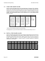
2.2.1.4.12 OLD-STYLE BK PRIORITY SCAN
The radio can be programmed to mimic the Old-Style BK Priority
Scan Modes as follows:
Mode
PR1
TX on PR1
PR2
A
Main
No
Off
B
Fixed Channel #
No
Off
C
Fixed Channel #
Yes
Off
See “Priority Scan” in section 3.11 of this manual for operational
details of the Old-Style BK Priority Scan Modes.
2.2.1.4.13 REVIEW GLOBAL PARAMETERS (GRP 00)
Press the [FCN] key repeatedly to display each setting in GRP
00, and then return to the GRP 00 starting point.
2.2.1.5
EXIT PROGRAMMING MODE
1. Rotate the OFF-VOL knob counterclockwise to the OFF position.
2. The radio will be in normal Operating Mode the next time it is turned on.
2.2.2
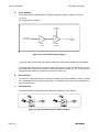
CLONING RADIO SETTINGS
Any “Master” radio (a GPH-CMD with the desired radio frequencies and settings) is capable of
transferring its program to another GPH-CMD or GPH radio. The radio receiving the program is
referred to as the “Slave” or “Clone.” The LAA0700 cloning cable will be required in the following
procedure.
Data that can be cloned to another GPH-CMD radio includes:
CMND CLN
Group data
Command Group data
Global data
UTXG Pick List
When the Master’s Command Group is cloned to a slave, the channel data
that is ‘pointed to’ by the Command Group is transferred to a target group
(not the Command Group) in the slave. The target group’s label in the slave
will be set to “CMND CLN”.
Data that can be cloned to a standard GPH radio includes:
Group data
Command Group data
When cloning to a GPH radio, the Master’s global data is converted to group
data in the slave, and only the first 16 channels are transferred.
BK RADIO
Page 2-13
Installation and Programming
GPH-CMD VHF Radio
When receiving an incoming clone from a GPH radio, the GPH-CMD radio
ignores group data other than the group label and the group scan list bit.
The GPH-CMD’s global data and channels 17-20 are not disturbed.
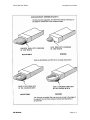
Master
Clone
NOTE: Some groups may be “locked” by PC programming to prevent them
from being overwritten. Only “unlocked” groups will accept incoming
clones.
1. Make sure the battery packs for both radios are charged.
2. Attach the master switch end of the cloning cable to the side connector
of the Master radio.
Master
Switch
NOTE:
PSWRD-******
PROG
ch
00
One plug of the cloning cable has a push-button master
switch. This plug must be attached to the Master radio.
3. Turn on the Master radio.
4. Put the Master radio in Programming Mode by pressing and holding the
master switch then pressing and holding the [FCN] key until the display
shows ‘PSWRD-******’. Enter the 6-digit password. The display shows
‘PROG CH 00.’
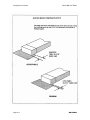
5. Connect the other plug of the cable to the side connector of the radio
you want to clone.
6. Turn on the clone and set it to the desired channel group.
PROG|GPHcmD
Group 01
Press and Hold [*] Key
to Change Target
PROG|GPH
Group 01
7. Press the [*] key on the Master radio keypad. The radio will respond
showing the prompt ‘PROG|GPHCMD’ on the first line and ‘Group XX’
on the second line, where XX is the currently selected group (see Select
A Group/Channel, section 3.8 of this manual, for details of how the
group is selected).
Long [*] keypresses will toggle the first line of the display between
PROG|GPHCMD’ and ‘PROG|GPH’, if the second line of the display
shows data that is valid to copy to the displayed target.
Data
GROUP 00
GROUP 01 - 25
CMND GRP
PICK LIST
PROG|GPHcmD
cmnd group
Press and Hold [#] Key
to Change Data
PROG|GPHcmD
pick list
Page 2-14
Valid Target
GPHCMD only
GPHCMD, GPH
GPHCMD, GPH
GPHCMD only
8. Long [#] keypresses will cause the second line of the display to cycle
through the data blocks that can be transferred to the target displayed on
the first line.
Target
GPHCMD
GPH
Valid Data
GROUP 00 or GROUP 01 - 25
CMND GRP
PICK LIST
GROUP 01 – 25
CMND GRP
BK RADIO
GPH-CMD VHF Radio
Installation and Programming
9. Once the target and data to be transferred have been selected, press
the [FCN] key on the Master radio keypad. The top line of the display
will flash ‘CLONING’ while the program in the master is being
downloaded to the clone.
CLONING
Group 01
10. If the download was successful, the display on the Master will again
display the clone prompt (target and data to be transferred).
•
To clone another channel group, press the Master radio’s [CLR]
key. Navigate to a ‘CH’ prompt, then press and hold the [#] key to
get the ‘GRP’ prompt.
•
If cloning is finished, turn off the Clone and disconnect the cloning
cable. Normal radio operation will occur when you turn on the Clone.
11. If the download was not successful, the master will flash ‘FAILURE’ and
multiple beeps will follow. Failure of downloading can be due to:
FAILURE
Group 01
1
2
3
FCN
4
5
6
PRI
7
8
9
ENT
*
0
#
CLR
•
Improper connection
•
Failure to turn on the clone
•
Setting the clone in Programming Mode
•
Target radio’s group ‘locked’ by PC Programming
NOTE:
BK RADIO
To stop the ‘FAILURE’ Mode, press [CLR], turn off both
radios, and try again, starting with Step 1 on the previous
page.
Page 2-15
Installation and Programming
2.3
GPH-CMD VHF Radio
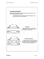
TONE CODE GUARD VALUES
The Tone Code Guard system may be set for any frequency in the range of 67 to 255.9 Hz.
However, since most systems adhere to the Electronic Industry Association (EIA) standards,
tones should be selected from the following EIA list. In order to insure optimum performance, tone
selection for use on the same radio frequency (RF) channel or adjacent channels in the same
coverage area should be made from one of the Groups A, B, or C to the maximum degree
possible. BK Radio guarantees optimum receiver performance only if tone frequencies below
220 Hz are chosen.
GROUP A
67.0 (XZ)
*151.4 (5Z)
162.2 (5B)
77.0 (XB)
88.5 (YB)
173.8 (6A)
*100.0 (1Z)
186.2 (7Z)
107.2 (1B)
203.5 (M1)
218.1 (M3)
114.8 (2A)
123.0 (3Z)
233.6
250.3
131.8 (3B)
141.3 (4A)
GROUP B
71.9 (XA)
146.2 (4B)
82.5 (YZ)
156.7 (5A)
94.8 (ZA)
167.9 (6Z)
103.5 (1A)
*179.9 (6B)
192.8 (7A)
110.9 (2X)
*118.8 (2B)
210.7 (M2)
127.3 (3A)
225.7 (M4)
241.8
136.5 (4Z)
GROUP C
74.4
79.7
85.4 (YA)
91.5 (ZZ)
* 50/60 Hz power distribution systems could cause falsing.
The assignments in a given area shall be made from within one of the Groups: A, B, or C.
2.4
DIGITAL CODE GUARD VALUES
Codes for the Digital Code Guard system may be chosen from the following list. This can be done
during the code programming of the system. Usually systems using direct unit to unit
transmission (systems without mobile relays, repeaters, remote control, etc) may use codes from
the table. Systems with relays etc. may use code variations for system control and operational
efficiency. The system operator or engineer should be consulted regarding the operational
requirement on such systems.
023
025
026
031
032
043
047
051
054
Page 2-16
065
071
072
073
074
114
115
116
125
131
132
134
143
152
155
156
162
165
172
174
205
223
226
243
244
245
251
261
263
265
271
306
311
315
331
343
346
351
364
365
371
411
412
423
431
432
445
464
465
466
503
506
516
532
546
565
606
612
624
627
631
632
654
662
664
703
712
723
731
732
734
743
754
BK RADIO
SECTION III
OPERATION
3.1
INTRODUCTION
This section contains information concerning the operation procedures for the BK Radio GPHCMD radios. The GPH-CMD radio has been designed to meet the tough requirements of today’s
communications environment. Please take a moment to read the information in this manual so
you can get optimum performance from your new radio.
3.1.1
3.2
FEATURES
•
Programmable Top Switches
•
Programmable Keypad Menu
•
Customizable Command Group
•
User Selectable TX Code Guard
•
DTMF/ANI
•
Transmit Time-Out Timer
•
Group Scan
•
Scan Delay
•
Talkback Scan
•
Nuisance Channel Delete
•
Dual-Priority Scan with Code Guard
•
Alphanumeric Display
•
Up to 500 Channels Available in 25 Groups of 20 Channels
•
2.5 kHz Interstitial Frequency Capability
•
Keypad Lock
FCC REQUIREMENTS
Your radio must be properly licensed by the Federal Communications Commission prior to use.
Your BK Radio dealer can assist you in meeting these requirements. Your dealer will program
each radio with your authorized frequencies, signaling codes, etc., and will be there to meet your
communications needs as your system expands.
BK RADIO
Page 3-1
Operation
3.2.1
GPH-CMD VHF Radio
RF ENERGY EXPOSURE AWARENESS AND CONTROL INFORMATION,
OPERATIONAL INSTRUCTIONS FOR FCC OCCUPATIONAL USE REQUIREMENTS
AND
BEFORE USING YOUR PORTABLE 2-WAY RADIO, READ THIS IMPORTANT
RF ENERGY AWARENESS AND CONTROL INFORMATION AND
OPERATIONAL INSTRUCTIONS TO ENSURE COMPLIANCE WITH THE
FCC’S RF EXPOSURE GUIDELINES.
NOTICE: This radio is intended for use in occupational/controlled conditions,
where users have full knowledge of their exposure and can exercise
control over their exposure to meet FCC limits. This radio device is
NOT authorized for general population, consumer, or any other use.
This 2-way radio uses electromagnetic energy in the radio frequency (RF) spectrum to provide
communications between two or more users over a distance. It uses radio frequency (RF)
energy or radio waves to send and receive calls. RF energy is one form of electromagnetic
energy; other forms include electric power, radar, sunlight and x-rays. RF energy, however,
should not be confused with these other forms of electromagnetic energy, which when used
improperly can cause biological damage. Very high levels of x-rays, for example, can damage
tissues and genetic material. The energy levels associated with radio waves from portable 2-way
radios, when properly used, are not great enough to cause biological damage.
Experts in science, engineering, medicine, health and industry work with organizations to
develop standards for exposure to RF energy. These standards provide recommended levels of
RF exposure for both workers and the general public. These recommended RF exposure levels
include substantial margins of protection. All 2-way radios marketed in North America are
designed, manufactured and tested to ensure they meet government established RF exposure
levels. In addition, manufacturers also recommend specific operating instructions to users of 2way radios.
These instructions are important because they inform users about RF energy exposure and
provide simple procedures on how to control it. Please refer to the following WEBSITES for more
information on what RF energy exposure is and how to control your exposure to assure
compliance with established RF exposure limits.
http://www.fcc.gov/oet/rfsafety/rf-faqs.html
http://www.osha.gov/SLTC/radiofrequencyradiation/index.html
3.2.2
FEDERAL COMMUNICATIONS COMMISSION REGULATIONS
The FCC rules require manufacturers to comply with the FCC RF energy exposure limits for
portable 2-way radios before they can be marketed in the U.S. When 2-way radios are used as a
consequence of employment, the FCC requires users to be fully aware of and able to control
their exposure to meet occupational requirements. Exposure awareness can be facilitated by the
use of a product label directing users to specific user awareness information. Your BK Radio 2way radio has a RF exposure product label. Also, your BK Radio owner’s and service manuals
include information and operating instructions required to control your RF exposure and to satisfy
compliance requirements.
Page 3-2
BK RADIO
GPH-CMD VHF Radio
3.2.3
Operation
COMPLIANCE WITH RF EXPOSURE STANDARDS
Your BK Radio 2-way radio is designed and tested to comply with a number of national and
international standards and guidelines (listed below) for human exposure to radio frequency
electromagnetic energy. This radio complies with the IEEE and ICNIRP exposure limits for
occupational/controlled RF exposure environment at operating duty factors of up to 50%
transmitting and is authorized by the FCC for occupational use only. In terms of measuring RF
energy for compliance with the FCC exposure guidelines, your radio radiates measurable RF
energy only while it is transmitting (during talking), not when it is receiving (listening) or in
Standby Mode. Note: The approved batteries supplied with this radio are rated for a 5-5-90 duty
factor (5% talk-5% listen - 90% standby), even though this radio complies with the FCC
occupational RF exposure limits and may operate at duty factors of up to 50% talk.
Your BK Radio 2-way radio complies with the following RF energy exposure standards and
guidelines:
United States Federal Communications Commission, Code of Federal Regulations;
47 CFR §§ 1.1307, 1.1310, 2.1091 and 2.1093
American National Standards Institute (ANSI) / Institute of Electrical and Electronic
Engineers (IEEE) C95. 1-1992
Institute of Electrical and Electronic Engineers (IEEE) C95.1-1999 Edition
3.2.4
INDUSTRY CANADA COMPLIANCE
This Class B digital apparatus complies with Canadian ICES-003.
Cet appareil numerique de la classe B est conforme à la norme NMB-003 Canada.
3.2.5
RF EXPOSURE
INSTRUCTIONS
COMPLIANCE
AND
CONTROL
GUIDELINES
AND
OPERATING
To control your exposure and ensure compliance with the occupational/controlled environment
exposure limits always adhere to the following procedures.
Guidelines:
BK RADIO
•
Do not remove the RF Exposure Label from the device.
•
User awareness instructions must accompany device when transferred to other users.
•
Do not use this device if the operational requirements described herein are not met.
Page 3-3
Operation
GPH-CMD VHF Radio
Operating Instructions:
•
Transmit no more than the rated duty factor of 50% of the time. To transmit (talk), push
the Push-To-Talk (PTT) button. To receive calls, release the PTT button. Transmitting
50% of the time, or less, is important because this radio generates measurable RF
energy exposure only when transmitting (in terms of measuring for standards
compliance).
•
Hold the radio in a vertical position in front of face with the microphone (and the other
parts of the radio, including the antenna) at least one inch (2.5 cm) away from the
nose. Keeping the radio at the proper distance is important because RF exposures
decrease with distance from the antenna. Antenna should be kept away from eyes.
•
When worn on the body, always place the radio in a BK Radio approved clip, holder,
holster, case, or body harness for this product. Using approved body-worn accessories
is important because the use of BK Radio or other manufacturer’s non-approved
accessories may result in exposure levels which exceed the FCC’s
occupational/controlled environment RF exposure limits.
•
If you are not using a body-worn accessory and are not using the radio in the intended
use position in front of the face, then ensure the antenna and the radio are kept at least
one inch (2.5 cm) from the body when transmitting. Keeping the radio at the proper
distance is important because RF exposures decrease with increasing distance from
the antenna.
•
Use only BK Radio approved supplied or replacement antennas, batteries, and
accessories. Use of non-BK Radio approved antennas, batteries, and accessories
may exceed the FCC RF exposure guidelines.
•
For a list of BK Radio approved accessories visit the following website:
http://www.relm.com.
CONTACT INFORMATION
For additional information on exposure requirements or other information, visit website
http://www.relm.com.
3.3
SAFETY PRECAUTIONS
• Do not operate the transmitter in close proximity to blasting caps.
• Do not operate the radio in an explosive atmosphere (petroleum fuels, solvents,
dust, etc.) unless your radio is an intrinsically safe model designed for such use.
Page 3-4
BK RADIO
GPH-CMD VHF Radio
3.4
Operation
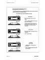
RADIO CONTROLS
TRANSMIT
TRANSMIT
INDICATOR
INDICATOR
BK RADIO
ANTENNA
ANTENNA
SQUELCH
SQUELCH
CODE
GUARD
CODE
GUARD
ON/OFF
VOLUME
CG-
GPH-CMD RADIO
DPH WITH
RADIO WITH
KEYBOARD/DISPLAY
KEYPAD/DISPLAY
COVERED OR
COVERED
NOT INSTALLED
(REDUCED
VIEW)
(REDUCED VIEW)
HI/LO
HI/LO
TRANSMIT
POWER
A
B
SQ
6
5
4
3
C
SCAN
SCAN
OFF-VOL
9 10
7 8
11
12
13
14
2 1 16 15
CHANNEL
SELECT
PRIORITY
INDICATOR BUSY CHANNEL
LOW BATTERY
PRIORITY
PRIORITY
BK RADIO
ANTENNA
SPEAKER
ACCESSORY
MOUNT
MICROPHONE
PROG
SCN
IDID
CG
CMND
CG
PRGTX
TXRX
SCN
RX
home channel
Tone 32
EARPHONE
G
R
P
PTT
(PUSH TO TALK)
LCD DISPLAY
1
2
3
4
5
6
PRI
7
8
9
ENT
*
0
#
CLR
FCN
KEYBOARD
PROG TX RX SCN ID CG CMND
home channel
Tone 32
Alphanumeric Display
BK RADIO
Page 3-5
Operation
3.5
GPH-CMD VHF Radio
BASIC OPERATION
3.5.1
RECEIVE
Turn power on by turning the Volume knob clockwise. A beep sounds,
indicating the radio is operational. The LCD display shows the current
channel.
Select a channel by rotating the Channel Selector knob. When the
unstopped channel selector is rotated past the highest (20th) channel, the
radio will emit a beep and remain on the highest channel. When rotated past
the lowest (1st) channel, the radio will emit a beep and remain on the lowest
channel.
Adjust squelch and volume by turning the Squelch knob clockwise until you
hear noise. Set the volume to a comfortable level. Then turn the Squelch
knob counterclockwise until the noise stops. This is called the Threshold
Squelch setting.
Turning the Squelch knob fully counterclockwise past the detent places the
receiver in Code Guard. A message will be heard only when the proper Code
Guard value is received.
3.5.2
TRANSMIT
Press the PTT (Push-To-Talk) switch. When the transmitter is on, the red
Transmit Indicator glows and TX appears in the display.
Talk in a normal voice with the microphone one to two inches from your
mouth.
Release the PTT switch to stop transmitting.
PTT
Microphone
If the Transmit Indicator does not glow when you press the PTT switch, the
battery pack may need to be charged. If so, the display will indicate
LOBATT, and the yellow Low-Battery Indicator will flash. If the Transmit
Indicator does not glow and a tone sounds, you are on a receive-only
channel or the channel is busy (if Busy Channel lockout is enabled). Select
an authorized transmit channel.
If the length of your message exceeds the preset Time-Out Timer setting,
the transmitter automatically shuts off and a tone sounds. To continue
transmission, release the PTT switch, and then press it again and continue
talking.
Page 3-6
BK RADIO
GPH-CMD VHF Radio
3.6
Operation
CODE GUARD OPERATION
Code Guard™ allows one radio or a group of radios to be selectively called within a system. If the
radio has been programmed with Code Guard, use the following receive and transmit
instructions.
3.6.1
CODE GUARD RECEIVE
Turn power on by turning the Volume knob clockwise.
Select a Code Guard channel by turning the Channel Selector knob.
Adjust volume by turning the Squelch knob clockwise until a noise is heard.
Set the volume to a comfortable level.
Set Code Guard Mode by turning the Squelch knob off (counterclockwise)
into the Code Guard position. A message will be heard only when the proper
Code Guard value is received.
3.6.2
CODE GUARD TRANSMIT
Turn the Squelch knob on (clockwise) and monitor the Code Guard
channel before transmitting, or, if Busy Channel operation is enabled, check
the yellow LED.
NOTE: Do not transmit if the channel is busy.
Busy Channel
Indicator
Press the PTT switch. When the transmitter is on, the red Transmit Indicator
glows and TX appears in the display.
If monitoring the channel, reset the squelch knob to the Code Guard position
to receive only the messages with the proper Code Guard value. During
extended transmissions, the squelch can be left open until the exchange has
ended.
Code Guard is a trademark of BK Radio, Inc.
3.7
COMMAND GROUP
The GPH-CMD radio allows construction of a Command Group of up to 20 channels, drawn from
any of the programmed channels in the radio. To modify the Command Group (add or delete
channels) all scanning functions (Channel Scan, Group Scan, and Priority Scan) must be turned
OFF.
BK RADIO
Page 3-7
Operation
GPH-CMD VHF Radio
3.7.1
BUILDING A COMMAND GROUP
1
2
3
FCN
4
5
6
PRI
7
8
9
ENT
*
0
#
CLR
CMND CHAN 5
After adding a channel, the display momentarily shows ‘CMND CHAN XX’
where XX is the channel number (1 – 20). Parameters associated with each
selected channel, such as Bandwidth, Scan, and Power settings, are also
used while operating in the Command Group.
Once 20 channels are entered, subsequent presses of the [*] key will cause
the radio to beep and momentarily display the message ‘CMND FULL’.
When operating in the Command Group, the continuously rotating channel
selector will “stop” at the highest programmed channel. For example, if only
4 channels are programmed, when the channel selector is rotated past the
4th channel the radio will beep and remain on the 4th channel.
CMND full
3.7.2
While operating in a group other than the Command Group (group 1 – 25),
the user selects a channel in the radio and presses the [*] key to enter the
channel into the Command Group. If a channel is on the scan list in its home
group, it will also be on the Command Group’s scan list. Unprogrammed
channels cannot be added to the Command Group. Up to 20 channels may
be entered.
OPERATING FROM THE COMMAND GROUP
1
2
3
FCN
4
5
6
PRI
7
8
9
ENT
*
0
#
CLR
SCN
CMND
LABEL
7
3.7.3
The Command Group can be entered by pressing the [#] key twice.
Operation in the Command Group is indicated on the display by the ‘CMND’
icon.
Adding or deleting a channel to/from the Command Group’s scan list also
changes the channel’s status in its home group.
It is not valid for a priority channel to be set to a channel in the Command
Group. If, while operating in the Command Group, the [PRI] key is pressed
to designate a priority channel, the “target channel” that is pointed to by the
Command Group channel, will be marked as the priority channel.
MODIFICATION OF THE COMMAND GROUP
1
2
3
FCN
4
5
6
PRI
7
8
9
ENT
*
0
#
CLR
CMND
Chan deleted
CMND
cmnd empty
Page 3-8
When the Command Group is active, a short press of the [*] key deletes the
knob-selected channel, while a long press (4 seconds) deletes all channels in
the Command Group.
When a channel is deleted, the display momentarily shows ‘CHAN
DELETED’, and the following channels move up in the list. For example, if
channel 5 is deleted, channel 6 becomes the new channel 5, channel 7
becomes the new channel 6, etc. When all channels are deleted, the radio
beeps continuously and the display shows ‘CMND EMPTY’ along with the
‘CMND’ icon.
Exit the Command Group to add new channels.
BK RADIO
GPH-CMD VHF Radio
3.8
Operation
CHANNEL GROUPS
Channels are arranged in 25 groups of up to 20 channels.
3.8.1
SELECT A GROUP/CHANNEL
The rotary knob selects channels in the group selected by the keypad:
1
2
3
FCN
4
5
6
PRI
7
8
9
ENT
*
0
#
CLR
1. Press the [#] key on the keypad to display the current group number.
2. Press number keys for the new group number, or press [#] again to
select the Command Group.
When changing groups, invalid entries will not be accepted, and the
radio remains in the previously selected group.
3. Press the [ENT] key or wait 5 seconds. The radio returns to normal
operation for the new group, and the selected channel is displayed.
All selected scanning functions affect only the channels in the group
you are operating in.
3.9
PROGRAMMABLE TOP SWITCHES/FUNCTION MENU
The following functions can be assigned to the three top switches or the
keypad [FCN] key menu:
Scan
Priority
Scan
HI/LO
FUNCTION
FCN Key Menu Label
Low Power Select
TX LOW POWER
Channel Scan
CHANNEL SCAN
Priority Scan
PRI SCAN
Repeater Talk Around
TALK-AROUND
Group Scan
GROUP SCAN
Your dealer can also assign more than one function to the same top switch.
For example, both low-power select and RTA could be enabled by the same
switch.
NOTE: Assume for this manual that Switch ‘A’ has been programmed for
HI/LO Transmit Power, Switch ‘B’ has been programmed for
Scan, and Switch ‘C’ has been programmed for Priority Scan.
To access functions on the keypad [FCN] key menu:
1
2
3
FCN
4
5
6
PRI
7
8
9
ENT
*
0
#
CLR
1. Press the [FCN] key to display the function menu.
2. Repeatedly press [FCN] to step through the menu.
3. Press [PRI] to toggle the function on/off when the desired menu item is
displayed.
When the display flashes, the function is enabled.
BK RADIO
Page 3-9
Operation
GPH-CMD VHF Radio
3.9.1
KEYPAD LOCK
To lock/unlock the keypad, press and hold the [FCN] key. When locked,
“LOCKED” will be displayed if a key is pressed and a low beep will sound.
LOCKED
LOCKOUT EXCEPTIONS:
PTT unlocks the keypad during transmit for enabled DTMF key presses.
3.10 SCAN OPERATION
1. Slide Switch B (scan) up.
2. Slide Switch C (priority) down.
The display indicates scan operation by flashing SCN.
SCN
LABEL
3
RX SCN
LABEL
6
Scan operates only while the radio is not transmitting. The radio checks for
signals on channels in the preset Scan List, as well as the channel selected
by the Channel Selector knob.
When a signal is detected, scanning stops and the message is received. The
received channel is shown in place of the transmit channel.
Once the signal ends, the radio continues to monitor the channel for the
preset scan delay time before it resumes scanning.
3.10.1
SCAN CODE GUARD CHANNELS
1. Slide Switch B (scan) up.
2. Turn the Squelch knob completely counterclockwise, past the detent, to
the Code Guard position.
When a signal is detected, scanning stops while the radio checks for the
proper Code Guard value. If the signal contains the proper Code Guard
value, the radio receives the message. Otherwise, the radio resumes
scanning immediately.
3.10.2
NUISANCE CHANNEL DELETE
If your radio is programmed for Nuisance Channel Delete and Channel Scan
is assigned to a top switch (Switch B, for example), a Nuisance Channel can
be temporarily removed from the Scan List by sliding Switch B down and
then back up.
Page 3-10
BK RADIO
GPH-CMD VHF Radio
3.10.3
Operation
TRANSMIT WITH SCAN ON
When Switch B (scan) is up, the radio transmits on the channel selected by
the Channel Selector knob unless Talkback Scan is enabled or “Transmit on
Priority-1” is enabled (see Priority Scan operation).
1. Select a transmit channel by turning the Channel Selector knob.
2. Press and hold the PTT switch and talk in a normal voice.
When the PTT switch is released, the radio continues to monitor the selected
channel for the preset scan delay time before it resumes scanning.
3.10.4
TALKBACK SCAN
If your radio is programmed for Talkback Scan, press PTT while a channel is
active or while scan delay time remains. You will be responding on the
transmit frequency of the received channel.
Talkback Scan will not work if Priority Scan is also on and your radio is
programmed to always transmit on the Priority 1 channel.
3.10.5
CHANGE THE SCAN LIST
If the radio has not been programmed for Scan List Lock, the user may add
or remove channels from the Scan List. If user changes are enabled, follow
these steps to change the Scan List:
1. Slide Switches B (scan) and C (priority) down.
SCN
LABEL 12
1
2
3
FCN
4
5
6
PRI
7
8
9
ENT
*
0
#
CLR
3.10.6
2. Select a channel to be added or removed from the Scan List by turning
the Channel Selector knob. If the channel is already on the Scan List,
SCN appears in the display.
3. Press the [ENT] key to add a channel to the Scan List. A short beep
sounds and SCN appears in the display.
4. Press the [CLR] key to remove a channel from the Scan List. A short
beep sounds and SCN disappears from the display.
GROUP SCAN
Channels on each "Channel Scan List" in groups on the "Group Scan List"
are scanned sequentially. The selected group is always scanned when
Group Scan is enabled, even if that group is not on the Group Scan List.
BK RADIO
Page 3-11
Operation
GPH-CMD VHF Radio
3.11 PRIORITY SCAN
Priority Scan enables the radio to receive on any channel while monitoring
for a message on the designated priority channel(s). The radio samples each
priority channel at a preset rate (.25-2.0 seconds) regardless of activity on
any other channel. Priority Scan operates only while the radio is not
transmitting and can be used in combination with scan operation.
3
When Switch C (Priority) is up, the display flashes SCN. If a message is
received on a priority channel, the Priority Indicator lights, and the radio
receiver locks onto that channel for the duration of the transmission, unless a
higher priority channel interrupts.
8
Priority Scan can be used in combination with Code Guard with:
SCN
LABEL
PR
SCN
LABEL
•
Switch C (Priority) up
•
The Squelch knob in the Code Guard position (fully counterclockwise
detent position) and
•
The Priority Channel(s) programmed with Code Guard
If a message is received on a priority channel, the radio receiver locks on to
the priority channel and checks to see if the proper Code Guard value is
present. If the signal contains the proper Code Guard value, the radio
receives the message. Otherwise, the radio will re-check the channel every
4 seconds, until the activity on the channel ceases.
3.11.1
DUAL PRIORITY SCAN
Up to two of the radio’s 500 channels can be designated as priority
channels. These two, PR1 and PR2, are periodically tested for activity, even
if a different transmission is being listened to. Activity on PR2 preempts
activity on any of the non-priority channels. Receptions on PR1 have priority
over any other channel, including PR2.
Either priority channel can be programmed as a fixed channel, tied to the
Channel Selector knob, or programmed OFF. If the radio is programmed to
transmit on the first priority channel, transmissions will occur on PR1 when
operating in Priority Scan Mode.
If PR1 is a fixed channel, and the [PRI] key is not locked out, the user can
use the keypad to change groups, if necessary, move the channel selector
to a new channel and press the [PRI] key to choose a new PR1 channel.
Page 3-12
BK RADIO
GPH-CMD VHF Radio
3.11.2
Operation
OLD-STYLE BK PRIORITY SCAN
The radio can be programmed with one of three Priority Modes: A, B, or C.
The table below shows how the priority channels and the transmit channels
are selected in each mode.
3.11.3
Mode A
Mode B
Mode C
Priority Channel
Channel Knob
Preset
Preset
Transmit Channel
Channel Knob
Channel Knob
Priority Channel
PRIORITY MODE A WITH SCAN
In Priority Mode A, the priority channel is set by the Channel Selector knob.
Priority Mode A is seldom used by itself because the radio receives and
transmits only on the knob-selected channel.
RX SCN
LABEL
12
When Switches B (scan) and C (priority) are up, scanning occurs until an
active scan channel is found. The radio receives the message while
continuing to check the priority channel. The display shows the scan channel.
If the priority channel becomes active during this message, the Priority
Indicator will light. The radio changes to the priority channel and holds for the
duration of the message. The display shows the priority channel.
PR
RX SCN
LABEL
3.11.4
3
To reply to a message on the priority channel, press the PTT switch and the
radio will transmit on the priority channel. Once activity ceases on the priority
channel, the radio returns to scan operation.
PRIORITY MODE B
With Switch C (priority) up and Switch B (scan) down, the radio can receive
on the knob-selected channel while sampling the priority channel. If the
priority channel becomes active, the Priority Indicator lights up. The radio
changes to the priority channel and holds for the duration of the transmission.
To reply to a message on the priority channel, use the keypad to change
groups if necessary, turn the Channel Knob to select the priority channel, and
then transmit.
3.11.4.1
PRIORITY MODE B WITH SCAN
With Switches B (scan) and C (priority) up, the radio scans until it locks on to
an active channel. The radio continues to sample the priority channel while
listening to the active scan channel.
If activity occurs on the priority channel, the radio overrides the active scan
channel, changes to the priority channel, and holds for the duration of the
transmission.
BK RADIO
Page 3-13
Operation
GPH-CMD VHF Radio
To reply to a message on the priority channel, use the keypad to change
groups if necessary, turn the Channel Knob to select the priority channel, and
then transmit.
Once activity has ceased on the priority channel, the radio returns to scan
operation.
3.11.5
PRIORITY MODE C
With Switch C (priority) up and Switch B (scan) down, the radio samples the
fixed priority channel at the preset rate. If activity occurs on the priority
channel, the radio changes to the priority channel and holds for the duration
of the transmission.
To reply to a message on the priority channel, press the PTT switch. The
radio transmits only on the priority channel when Switch C (priority) is up.
Once activity has ceased on the priority channel, the radio returns to the
receive channel on the Channel Selector knob.
3.11.5.1
PRIORITY MODE C WITH SCAN
With Switches B (scan) and C (priority) up, the radio scans until it locks on to
an active channel. The radio continues to sample the priority channel while
listening to the active channel. If activity occurs on the priority channel, the
radio overrides the active scan channel, changes to the priority channel, and
holds for the duration of the transmission.
To reply to a message on the priority channel, press the PTT switch. The
radio transmits only on the priority channel when Switch C (priority) is up.
Once activity has ceased on the priority channel, the radio returns to scan
operation.
3.11.6
CHANGE THE PRIORITY 1 CHANNEL
The fixed Priority 1 channel can be permanently set or can be changeable. If
the radio has a changeable priority channel, use the following steps to make
this change:
1. Slide Switches B (scan) and C (priority) down.
2. Use the keypad to change groups, if necessary. Turn the Channel
Selector knob to the channel you want to enter as the new Priority 1
channel.
1
2
3
FCN
4
5
6
PRI
7
8
9
ENT
*
0
#
CLR
PR
LABEL
Page 3-14
3
3. Press the [PRI] key. A short beep sounds and PR appears in the
display, indicating that the displayed channel is now the Priority 1
channel.
NOTE: If the radio is programmed for Dual Priority operation, only the
Priority 1 channel can be changed with the [PRI] key.
NOTE: A channel can be the priority channel even if it is on the Scan
List. Due to multiple sampling of the same channel, however,
maximum performance occurs when the priority channels are not
on the Scan List.
BK RADIO
GPH-CMD VHF Radio
Operation
3.12 USER TRANSMIT CODE GUARD
When the radio is being programmed with transmit and receive frequencies for each channel, a
receive Code Guard value and a transmit Code Guard value can also be assigned to each
channel. On channels that do not have a default transmit Code Guard programmed, the user can
choose CxCSSs from a global UTXG Pick List containing 32 entries. To assign a UTXG for use
on a channel, all scanning functions (Channel Scan, Group Scan, and Priority Scan) must be
turned OFF.
The user selects a channel and then uses the keypad to enter a number from
1 to 32. When UTXG is active, the second line of the display will show the
number of the selected list entry (TONE – XX). Once a UTXG is assigned to
a particular channel, it will be stored and used with that channel whenever
the channel is selected. Repeater Talk Around operation will use the preprogrammed RX CxCSS.
LABEL 20
TONE 8
The UTXG Pick List can be viewed by pressing [FCN] [1]. The display will
show:
TONE - 01
000.00
TONE – 01
XXX.X
1
2
3
FCN
4
5
6
PRI
7
8
9
ENT
*
0
#
CLR
or
TONE – 01
DXXX
Press [PRI] to increment through the list or key in a number. Press [ENT] to
exit the list viewer. (This feature is for viewing the list only. Pressing [ENT]
when a list item is displayed does NOT associate the UTXG with the selected
channel.)
Programming of the list (if programming is not locked out by PC software)
can be accomplished as follows:
1. While viewing the list, press and hold the [FCN] key until the ‘PROG’
annunciator lights.
2. Press [CLR] and then enter the new CxCSS. Press [ENT] to store the
new value and return to the list viewer.
3.13 OTHER OPERATIONAL FEATURES
The BK Radio GPH-CMD Series is based on a microprocessor core that allows extra features
and operational characteristics to be programmed into the radio. Your dealer can help define the
best operational settings for your system and program them into the radio.
3.13.1
SCAN DELAY
Scan delay lets the radio receive a response to a transmission before
scanning the other channels for activity. If you find that your scanner is
restarting before message replies are received, you can ask your dealer to
increase the scan delay time (0-7.5 seconds).
This timer is also used to allow for Talkback Scan.
BK RADIO
Page 3-15
Operation
GPH-CMD VHF Radio
3.13.2
HI/LO POWER
Each channel in the radio can be individually programmed to always transmit
in Low-Power Mode, regardless of the position of the radio's top switch (or
keypad [FCN] menu setting). If the programming for the channel allows highpower transmissions, the power level can be selected with a top switch or the
keypad menu.
3.13.3
DTMF ENCODING
1
2
3
FCN
4
5
6
PRI
7
8
9
ENT
*
0
#
CLR
Radios can be programmed to enable DTMF (Dual Tone Multiple Frequency)
encoding. To send DTMF tones (similar to the tones used by a standard
push-button telephone):
1. Press and hold the PTT switch.
2. Press any of the keys on the keypad.
You will hear a sidetone.
The FCN, PRI, ENT, and CLR keys respond as DTMF tones A, B, C, and D,
respectively.
3.13.4
ANI ENCODING
1
2
3
FCN
4
5
6
PRI
7
8
9
ENT
*
0
#
CLR
3.13.5
ANI encoding (Automatic Numeric Identification), if enabled, transmits a
sequence of DTMF tones each time you press the PTT switch. You will hear
a sidetone. Your dealer can program the ANI number to be sent.
If DTMF and ANI are both enabled, the ANI tone sequence is transmitted
only after the [ENT] key is pressed while the PTT switch is activated. You will
hear a sidetone.
TIME-OUT TIMER
The transmit Time-Out Timer limits the duration of calls and guards against
accidentally locking on the transmitter and tying up the radio system. Your
dealer can program the duration of the Time-Out Timer (15-225 seconds, or
disabled).
3.13.6
BUSY CHANNEL
If the radio has been programmed for Busy Channel operation, it will operate
in one of the following three Modes:
Page 3-16
•
Busy Channel Indication
•
Busy Channel Lockout
•
Busy Channel Lockout with Override
BK RADIO
GPH-CMD VHF Radio
3.13.6.1
Operation
BUSY CHANNEL INDICATION
The yellow Busy Channel Indicator glows if there is carrier activity on the
selected channel. If the selected channel is a Code Guard channel and the
proper Code Guard value is not detected, the Busy Channel Indicator
remains on for the duration of the carrier activity and no message is heard.
During Scan and Priority Scan operation, the Busy Channel Indicator glows
when activity is detected on any channel on the Scan List.
When scanning or priority scanning Code Guard channels with the Squelch
knob in the Code Guard position and activity has been detected, the Busy
Channel Indicator glows for the time period necessary to determine if the
proper Code Guard value has been received. This will cause the Busy
Channel Indicator to flash at various rates.
3.13.6.2
BUSY CHANNEL LOCKOUT
The Busy Channel Lockout feature applies only to those channels
programmed with a receive Code Guard value. When carrier activity is
detected on the channel selected, the radio checks the receive Code Guard
value. If the proper Code Guard value is present, the radio can transmit on
that channel, even if the Squelch knob is in the Code Guard position.
BUSY
If the radio detects an incorrect value or carrier activity only, the transmitter
is disabled. If an attempt is made to transmit, an alert tone will be generated
and the display will show the word BUSY until the channel becomes
available or the PTT switch is released, whether the Squelch knob is in or
out of the Code Guard detent.
Channels not programmed with a receive Code Guard value can be used to
transmit regardless of carrier activity.
3.13.6.3
BUSY CHANNEL LOCKOUT WITH OVERRIDE
This mode operates in the same manner as Busy Channel Lockout except
that the user can override and transmit by turning the Squelch knob off the
Code Guard detent. The transmitter is locked out only if the Squelch knob is
set to the Code Guard detent.
BK RADIO
Page 3-17
Operation
GPH-CMD VHF Radio
3.14 ALPHANUMERIC DISPLAY
GPH-CMD radios may optionally have a slide-out keypad/display cover. To
remove or install the cover, turn off the radio and remove the battery (see
Battery Installation and Removal, section 2.1.2 of this manual).
Display annunciators indicate the following information:
ALPHANUMERIC
INDICATION
PR
-Priority Channel
PROG
-Programming Mode
TX
-Transmit
RX
-Receive
SCN
-Scan List Channel
-Flashing SCN indicates scanning in progress, and
RX SCN indicates receiving on a scanned channel.
ID
-Programming Mode - Automatic Numeric Identification
(ANI)
CG
-Programming Mode – Code Guard
CMND
-Command Group Active
PROG TX RX SCN ID CG CMND
home channel
Tone 32
FIGURE 3-1 Liquid Crystal Display
Page 3-18
BK RADIO
GPH-CMD VHF Radio
Operation
GPH-CMD Series portable radios can be programmed with the following
features:
3.14.1
DISPLAY BACKLIGHTING
The GPH-CMD radios can be programmed by your dealer to backlight the
display when a signal is received or when a key is pressed. The time
duration of the backlighting can also be programmed.
3.14.2
CHANNEL AND GROUP LABELS
The radio can be programmed with a label for each of the 25 channel groups
and a label for each of the 20 channels within each group.
To display a group label, turn scanning functions off, then:
1
2
3
FCN
4
5
6
PRI
7
8
9
ENT
*
0
#
CLR
BK RADIO
1. Press the [#] key on the keypad to display the group number.
2. Press and hold the [#] key to display the group label.
3. Press the [ENT] key or wait for about 5 seconds to revert to normal radio
operation.
Page 3-19
Operation
GPH-CMD VHF Radio
3.15 DEFINITIONS AND ACRONYMS
ANI
CG
CLR
Cloning
Automatic Numeric Identification
Code Guard
Clear
The process of copying data from one radio, called
“master,” to other radios, called “slaves” or “clones.”
Code Guard
A sub-audible tone for selective calling and
receiving.
Command
A group of up to 20 channels selected by the user
Group
from any of the 500 channels in the radio.
Detent
The click/hesitation you feel as you turn a knob from
one position to another.
DTMF
Dual Tone Multiple Frequency
DTMF Tones
Tones that sound like those used by a standard
push-button telephone.
ENT
Enter
FCN
Function
Individual
The information programmed with a PC on both a
Personality
global and by-channel basis that tells the radio
exactly how to operate.
LCD
Liquid Crystal Display
PROG
Program
PRI
Priority
PTT
Push To Talk
RTA
Repeater Talk Around
RTX Channel
Ready to Transmit Channel
RX
Receive
SCN
Scan
SQ
Squelch
Squelch
A control that eliminates background noise.
Talkback Scan When scanning, if a signal is present, the scan will
stop and you will hear the signal. If you can then
push the PTT switch to talk back to the person, you
are in Talkback Scan Mode.
Time-Out Timer A feature that limits the duration of calls.
TX
Transmit
UTXG
User Transmit Code Guard
Page 3-20
BK RADIO
SECTION IV
THEORY OF OPERATION
4.1
INTRODUCTION
This section contains the theory of operation for the BK Radio GPH-CMD radio. To help you understand
the operation of the equipment, refer to the schematic diagrams in Section VI of this manual.
4.2
DESCRIPTION
The GPH-CMD radios are self-contained VHF FM Radios covering the frequency range of 136 MHz to
174MHz. The radios are multi-channel and digitally synthesized using a single crystal for frequency
control. All models incorporate an EEPROM for the storage of Channel Frequency, Code Guard™, and
Dual Tone Multiple Frequency/Automatic Numeric Identifier (DTMF/ANI) encode information. All models
also include low-battery and busy-channel indicators. Toggle switches can be programmed to control
Hi/Low Transmit Power, Channel Scan, Priority Scan, Repeater Talk-Around, and Group Scan. Status
and channel information is displayed over a liquid crystal display Connectors are provided on the side of
the unit for an external antenna, microphone, speaker, and other optional accessories. A variety of twistoff battery packs are also available.
4.3
THEORY OF OPERATION
Circuitry for the GPH-CMD Series radio comprises five major circuits:
4.3.1
•
The RECEIVER, which consists of RF Preselectors, RF Preamplifier, Mixer, IF Filters, IF Amplifiers,
FM IF IC, and Noise Squelch circuitry.
•
The TRANSMITTER, which consists of a Power Amplifier, Harmonic Filter, Antenna Switch, and
Power Control circuitry.
•
The SYNTHESIZER, which consists of a Voltage Controlled Oscillator (VCO), VCO Buffer,
Synthesizer Buffer, Synthesizer IC, Temperature Compensated Crystal Oscillator (TCXO)
Reference, Loop Filter, VCO Coarse Tune Adaptive Filter, 3.0V and 4.5V Voltage Regulators.
•
The SYSTEMS area, which consists of a Microprocessor, EEPROM, VCO Coarse Tune, Front End
Tuning and Power Set, 3.3V Regulator, 5V Regulator, -15V Regulator, 7.0V Regulator and LowBattery Shutdown, Receive Audio, Deviation Compensation and Squelch Adjustment.
•
The DIGITAL SIGNAL PROCESSING (DSP) area, which consists of a Digital Signal Processor,
Flash Memory, CODEC, TCXO, 1.5V and 3.3V Voltage Regulators.
RECEIVER
The Receiver is a dual-conversion design with intermediate frequencies of 16.9 MHz and 455 kHz. RF
signals received at the antenna pass through the Antenna Switch and Front End. The Front End consists
of an amplifier and two Microprocessor-tuned bandpass filters. The Front End amplifies the receive
frequency and attenuates image, half IF, and other frequencies that degrade Receiver performance.
BK RADIO
Page 4-1
Theory of Operation
GPH-CMD VHF Radio
RF signals from the Front End enter a Mixer that converts them to 16.9 MHz. The 16.9 MHz IF signal
passes through two crystal filters that provide adjacent channel selectivity. The IF amplifier then amplifies
the signal and couples it to the 455 kHz IF integrated circuit. The 455 kHz IF IC consists of a Mixer,
limiter, demodulator, and squelch circuit. The 16.9 MHz signal enters the Mixer and is converted to a 455
kHz IF signal. A ceramic filter at 455 kHz provides more adjacent channel selectivity. The signal is then
amplified by the limiter and demodulated. Audio processing is then done on the options board. Filtered
audio noise is used to provide a squelch indication.
Figure 4-1 Receiver Block Diagram
A.
RF Preselectors
The Preselectors provide greater than 75 dB of attenuation at the image frequency. Both bandpass
filters are varactor tuned, which allows a wide frequency spread. Overall, the preselectors exhibit a
bandwidth of 4.5 MHz. The preselectors consist of L2, L3, L4, L5, and associated circuitry.
B.
RF Preamplifier
The RF Amplifier is a single-IC amplifier providing 22 dB of gain.
C.
Mixer
The balanced diode Mixer converts the RF frequency to 16.9 MHz.
D.
1st IF Filters and IF Amplifier
The Crystal Filters are centered at 16.9 MHz and provide attenuation to frequencies adjacent to
the receive frequency. There are two sets of 1st IF Filters - one for wideband (25/30 kHz) mode,
and the other for narrowband (12.5/15 kHz) mode. The IF Amplifier provides 26 dB of gain at 16.9
MHz.
Page 4-2
BK RADIO
GPH-CMD VHF Radio
E.
Theory of Operation
FM IF IC
The FM IF IC provides a second Mixer, a high-gain limiter, a demodulator, an OP-AMP, and a
Schmitt trigger. The Mixer converts the 16.9 MHz signal to 455 kHz. The local oscillator for the
Mixer consists of a 17.355 MHz crystal and associated circuitry. The 455 kHz signal is filtered by a
ceramic filter. A limiter provides most of the gain for the Receiver. The FM signal is demodulated
by the demodulator, the ceramic discriminator, and associated circuitry.
F.
Noise Squelch
The demodulated audio is bandpass filtered with an active filter consisting of the internal OP-AMP
of the FM IF IC and external circuitry. Squelch gain is controlled by the Microprocessor. The
squelch noise is detected by the internal Schmitt trigger of the FM IF IC. The Microprocessor
samples the Schmitt trigger output to determine signal level and squelch information.
4.3.2
TRANSMITTER
The Transmitter consists of four major blocks (see figure below):
A.
Power Amplifier
B.
Harmonic Filter
C.
Antenna Switch
D.
Power Control Circuit
Figure 4-2 Transmitter Block Diagram
The Power Amplifier provides the necessary gain to amplify the VCO signal to a level of 5 Watts.
The Harmonic Filter is a seven-pole low-pass filter that provides rejection of the harmonics of the
transmit frequency.
The Antenna Switch routes the RF signal from the Transmitter to the antenna port while in Transmit
Mode. In Receive Mode, the antenna port is routed to the Receiver.
The Power Control circuit uses feedback to level the RF power from the Transmitter.
BK RADIO
Page 4-3
Theory of Operation
A.
GPH-CMD VHF Radio
Power Amplifier
The Power Amplifier comprises two RF amplifier stages (see Figure 4-3 below). These are:
(1) Driver
(2) Integrated Power Module
Power
Control
L.O. Input
(from VCO)
Q1
Driver
Stage
U4
To
Harmonic
Filter
Power
Module
Figure 4-3 Power Amplifier Block Diagram
The Driver stage provides gain and isolation between the VCO and the Integrated Power Module.
The Integrated Power Module provides sufficient RF power to meet the radio's output power
specification after losses in the Harmonic Filter and Antenna Switch. The DC current into the
Integrated Power Module is monitored by the Power Control circuit.
B.
Harmonic Filter
The Harmonic Filter attenuates the harmonics created by the Power Amplifier to meet or exceed
the transmit spurious and harmonic specification. The passband input and output impedances of
the filter are 50 Ohms.
C.
Antenna Switch
The Antenna Switch connects either the Transmitter or Receiver to the antenna.
Figure 4-4 Antenna Switch Functional Block Diagram
Page 4-4
BK RADIO
GPH-CMD VHF Radio
Theory of Operation
In Transmit Mode, both pin diodes in the Antenna Switch are turned on, completing a signal path
from the Transmitter and shunting the Receiver path to ground. In Receive Mode, both pin diodes
are turned off, allowing RF signals to flow to the Receiver with the Transmitter output port removed
from the circuit.
D.
Power Control Circuit
The Power Control Circuit monitors the DC supply current to the Integrated Power Module. This
current increases with RF output power and is kept constant by the Power Control circuit.
Current sensing is accomplished using a small resistance in the DC supply to the Integrated Power
Module. The voltage developed across this resistance is fed to a bridge circuit and amplifier where
it is compared to the "PWR SET" voltage. Any difference in the levels is amplified and used to
control the bias current to the Integrated Power Module.
4.3.3
SYNTHESIZER
The Synthesizer generates an RF signal either to down-convert a desired receive frequency to a fixed IF
or to drive the Transmitter. The synthesizer is essentially a phase-locked loop that locks the RF output of
a Voltage Controlled Oscillator (VCO) to a very stable lower frequency reference. The DSP determines
the frequency that the synthesizer produces by programming the dividers contained within the
Synthesizer IC.
Adapt Pulse
Coarse Tune
RX/TX Band
Switch
Program
Lines
Phase Error
TCXO
Reference
Synthesizer
IC
Frequency Steering
Loop
Filter
VCO
Steering Line
VCO
Buffer
TX Modulation
Synthesizer
Buffer
Figure 4-5 Synthesizer Block Diagram
BK RADIO
Page 4-5
Theory of Operation
A.
GPH-CMD VHF Radio
Voltage Controlled Oscillator (VCO)
Transistor Q4 provides the gain, and an L-C resonant tank circuit provides the frequency selectivity
and phase shift necessary to produce an oscillator. Frequency control of the oscillator is
accomplished by the tuning tank circuit comprised of mechanically adjustable transformer T1 and
varactors CR4 and CR5. The cathode of CR4, connected to the Loop Filter, is used to lock the
VCO to the desired carrier frequency. The anode of CR4, connected to the Coarse Tune Adaptive
Filter, is used to pre-tune the VCO frequency within the lock range of the synthesizer. CR5 is
used in the Transmit Mode to modulate the carrier. The oscillator frequency range is 136-174 MHz
in the Transmit Mode and 119.1-157.1 MHz in the Receive Mode (low side injection). The 16.9
MHz shift from receive to transmit is achieved by turning on PIN diode CR3, thus adding L4 to the
tank circuit. Q5 and associated circuitry provide additional power supply filtering for the VCO.
Diode CR6 gives the filter a rapid power up response while maintaining a very low cutoff
frequency.
B.
VCO Buffer
The VCO Buffer is a cascode configuration with bipolar transistor Q3 feeding common gate FET
Q21. It isolates the VCO from the Receiver/Transmitter circuitry and provides enough power gain
to supply a nominal level of +7 dBm in receive and +5 dBm in transmit.
C.
Synthesizer Buffer
Synthesizer Buffer Q2 provides isolation between the Synthesizer IC and Receiver/Transmitter
circuitry and additional isolation between the Synthesizer IC and the VCO.
D.
Synthesizer IC
Synthesizer chip U6 contains a 5-bit integer reference divider and a main divider controlled by an
18-bit delta-sigma modulator. The delta-sigma fractional-N capability permits very fine frequency
resolution while using a very high phase detector sample rate. The charge pump phase detector
provides current pulses at the sample rate whose polarity and width are proportional to the phase
error between the divided reference and the divided VCO. The phase detector gain is
programmable and is adjusted across the operating frequency band to compensate for changes in
VCO steering line sensitivity. A separate frequency steering output is available from U6 that
provides a low resistance connection to either the 4.5V supply or ground if a significant frequency
error exists. In a locked condition, the frequency steering output is high impedance. U6 also
contains a direct digital modulation register that allows modulation signals within the bandwidth of
the phase locked loop to be applied to the VCO by writing samples to the register.
E.
TCXO Reference
The TCXO Reference, Y1, is a purchased module that provides ±2.5ppm stability over a
temperature range extending from -30°C to +60°C. The direct digital modulation register within U6
eliminates the need to pull the frequency of the Reference Oscillator in order to apply low
frequency modulation to the VCO.
F.
Loop Filter
The Loop Filter converts the phase detector current pulses into a filtered voltage that adjusts the
VCO frequency in a direction to maintain phase and frequency lock between the divided reference
and the divided VCO. The frequency steering output of U6 is summed into the Loop Filter to
reduce lock time when a significant change in VCO steering line voltage is required for a new
programmed frequency.
Page 4-6
BK RADIO
GPH-CMD VHF Radio
G.
Theory of Operation
VCO Coarse Tune Adaptive Filter
R26 and C50 form a low cutoff frequency pole to filter out noise on the Coarse Tune line to the
VCO. When changing to a new frequency that requires a different Coarse Tune voltage, switch
U11 is closed for a short time to allow the voltage on C50 to change to the new value rapidly.
H.
3.0V Regulator
U12 provides a low noise regulated 3.0V supply that powers the TCXO Reference Y1 and all
sections of the synthesizer IC U6 except the charge pump phase detector and frequency steering
circuit.
I.
4.5V Regulator
U13 provides a low noise regulated 4.5V supply that powers the charge pump phase detector and
frequency steering sections of the synthesizer IC U6.
4.3.4
SYSTEMS AREA
A variety of functions are included in the Systems area.
A 3.3V precision voltage regulator provides power to the Microprocessor and several other digital ICs in
the radio. A 5.0V precision voltage regulator serves as the primary regulated analog supply in the radio.
The 7.0V regulator is used to supply the VCO, VCO Buffer and Synthesizer Buffer. An output signal from
the 7.0V regulator will alert the processor if the battery voltage falls too low for proper operation of this
regulator. A -15V switching regulator generates the negative supply needed to produce the negative
VCO Coarse Tune and Receiver Front End Tune/Transmitter Power Set signals.
Several special Transmitter features are implemented by the Microprocessor. These include Repeater
Talk-Around, Busy Channel Lockout, DTMF Control, ANI Control, Sub-audible Code Guard Control, and
Transmit Time-Out Timer.
Receive Mode special features provided by the Microprocessor include Channel Scan, Dual Priority
Scan, Scan Hold Timer, and Battery Saver.
Other functions performed by the Microprocessor include: storing and retrieving hardware alignment and
channel information, tuning the Receiver Front End, setting the Transmit power level, setting the squelch
gain, interpreting the user switches, generating display information, and implementing remote and
keypad programming modes.
A.
Microprocessor
The Microprocessor U1 receives inputs from user switches and controls radio functions such as
adjusting the Transmitter deviation, tuning the Receiver, setting transmit power, time-out functions,
etc.
B.
EEPROM
The EEPROM U7 stores channel information and hardware compensation values.
C.
VCO Coarse Tune
D/A converter U2 and amplifier U10-A allow the Microprocessor to set the VCO Coarse Tune
voltage to any value within the range of 0V to -12V.
BK RADIO
Page 4-7
Theory of Operation
D.
GPH-CMD VHF Radio
Front End Tuning and Power Set
D/A converter U2 and amplifier U10-B allow the Microprocessor to set the Front End Tuning
voltage in Receive Mode and the Power Set voltage in Transmit Mode to any value in the range of
0V to -15V.
E.
3.3V Regulator
U14 provides a regulated 3.3V supply for the Microprocessor and other digital circuitry in the radio.
F.
5V Regulator
U8 provides a regulated 5V supply for the Receiver and other analog circuitry in the radio.
G.
7.0V Regulator and Low-Battery Shutdown
A 7.0V Regulator is composed of U3, Q10, and associated circuitry. Regulator operation is
monitored via Q11. The Microprocessor will shut down radio operation if a low-battery or 7.0V
short circuit occurs. Q1 is used to switch the regulator off during Battery-Saver Mode.
H.
-15V Regulator
U5, L8 and associated circuitry comprise a -15V switching regulator. Q25 is used to switch the
regulator off during Battery-Saver Mode.
I.
Receive Audio
U9 is a 0.5 Watt Audio amplifier. Muting is controlled by the Microprocessor. The audio level out
of U9 is controlled by the analog potentiometer connected to the Volume Knob, R51.
J.
Deviation Compensation
The transmit Deviation Compensation is accomplished by one of the two digital potentiometers in
U16. At higher Transmitter frequencies, less voltage is needed for VCO modulation, so this circuit
attenuates the signal. Also, when Code Guard tones are being transmitted, the deviation sensitivity
is reduced so that overall deviation remains constant.
K.
Squelch Adjustment
The second digital potentiometer in U16 provides programmable attenuation between the
discriminator audio output of the Receiver and the squelch threshold detection circuit of the
Receiver. The Microprocessor reads the voltage on the wiper of the analog potentiometer
connected to the Squelch Knob, R85, to determine the desired Squelch Level and programs U16
so that the desired threshold level is achieved.
.
Page 4-8
BK RADIO
GPH-CMD VHF Radio
4.3.5
Theory of Operation
DIGITAL SIGNAL PROCESSING
3.3 V
REGULATOR
SWITCHING
A +
(1.4 MHz SW FREQ)
3.3 V
LINEAR
1.8 V
REGULATOR
TCXO
1.8 V
19.6608 MHz
TX AUDIO
9.8304 MHz
CLK
SPEAKER
AUDIO
CODEC
DATA
DSP
ADRS
DATA
FLASH
MEMORY
DATA
COTROL
CONTROL
MIC
CONTROL /
COTROL
DATA BUS/
DISC
AUDIO
DATA BUS
TO CORE
uP
Figure 4-6 Digital Signal Processing Block Diagram
A.
Digital Signal Processor
The Digital Signal Processor implements filters, tone generators, and other signal processing
algorithms required for operation.
B.
Flash Memory
The Flash Memory stores the Digital Signal Processor software.
C.
CODEC
Converts analog signals to digital signals and vice versa.
D.
TCXO
Provides a stable oscillator frequency for Digital Signal Processor.
E.
Voltage Regulators
3.3 Volts is provided by a switching regulator. A linear regulator produces 1.5 Volts.
BK RADIO
Page 4-9
SECTION V
MAINTENANCE
5.1
INTRODUCTION
This maintenance section contains test and alignment procedures for an operational BK Radio
GPH-CMD radio. This section also contains troubleshooting and assembly/disassembly
procedures. An understanding of the theory of operation is recommended before maintenance is
attempted. All LAA kits and programming items are available from BK Radio.
5.2
TEST EQUIPMENT REQUIRED
A. RF Signal Generator:
HP8640B or equivalent
B. Distortion Analyzer:
HP334A or equivalent
C. RF Voltmeter (optional):
Boonton 92C or equivalent
D. RF Power Meter:
HP435B with 30 dB pad or equivalent
E. Service Monitor:
HP8920A Service Monitor or equivalent
F. Digital Multimeter:
Fluke 8012A or equivalent
G. Computer
IBM PC or Compatible, with an RS-232 Serial Port
LAA0725 Programming Cable
LAA0746 GPH-CMD Programming Software
H. Portable Radio Tool Kit:
I.
Test Cable Kit for
E-Series Portable Radios:
BK RADIO
LAA0600
LAA0608
Page 5-1
Maintenance
GPH-CMD VHF Radio
5.3
OVERHAUL
5.3.1
ACCESSORIES
This section contains instructions to assist in determining, by inspection, the condition of GPHCMD assemblies. Defects resulting from wear, physical damage, deterioration, or other causes
can be found by these inspection procedures.
A.
Capacitors, Fixed
Inspect capacitors for case damage, body damage, and cracked, broken or charred
insulation. Check for loose, broken, or corroded terminal studs, lugs, or leads. Inspect for
loose, broken, or improperly soldered connections. On surface mounted capacitors, be
especially alert for hairline cracks in the body and broken terminations.
B.
Capacitors, Variable
Inspect trimmers for chipped and cracked bodies, damaged dielectrics, and damaged
contacts.
C.
Chassis
Inspect the chassis for deformation, dents, punctures, badly worn surfaces, damaged
connectors, damaged fastener devices, loose or missing hardware, component corrosion
and damage to the finish.
D.
Coils
Inspect all coils for broken leads, loose mountings, and loose, improperly soldered, or
broken terminal connections. Check for crushed, scratched, cut, or charred windings.
Inspect the windings, leads, terminals, and connections for corrosion or physical damage.
Check for physical damage to forms and tuning slug adjustment screws.
E.
Connectors
Inspect connectors for broken parts and other irregularities. Inspect for cracked or broken
insulation and for contacts that are broken, deformed or out of alignment. Also check for
corroded or damaged plating on contacts and for loose, improperly soldered, broken or
corroded terminal connections.
F.
Covers and Shields
Inspect covers and shields for punctures, deep dents, and badly worn surfaces. Also check
for damaged fastener devices, corrosion, and damage to finish.
G.
Flex Circuits
Inspect flex circuits for punctures and badly worn surfaces. Check for broken traces,
especially near the solder contact points.
H.
Fuse
Inspect for blown fuse and check for loose solder joints.
Page 5-2
BK RADIO
GPH-CMD VHF Radio
I.
Maintenance
Insulators
Inspect insulators for evidence of damage, such as broken or chipped edges, burned areas
and presence of foreign matter.
J.
Jacks
Inspect all jacks for corrosion, rust, deformations, loose or broken parts, cracked insulation,
bad contacts, or other irregularities.
K.
Potentiometers
Inspect all potentiometers for evidence of damage or loose terminals, cracked insulation, or
other irregularities.
L.
Resistors, Fixed
Inspect the fixed resistors for cracked, broken, blistered, or charred bodies, and loose,
broken, or improperly soldered connections. On surface mount resistors, be especially alert
for hairline cracks in the body and broken terminations.
M.
Terminal Connections Soldered
1. Inspect for cold-soldered or resin joints. These joints present a porous or dull, rough
appearance. Check for strength of bond using the points of a tool.
2. Examine the terminals for excess solder, protrusions from the joint, pieces adhering to
adjacent insulation, and particles lodged between joints, conductors, or other
components.
3. Inspect for insufficient solder and unsoldered strands of wire protruding from conductor
at the terminal. Check for insulation that is stripped back too far from the terminal.
4. Inspect for corrosion at the terminal.
N.
Wiring/Coaxial Cable
Inspect wiring in chassis for breaks in insulation, conductor breaks, cut or broken lacing,
and improper dress in relation to adjacent wiring or chassis.
5.3.2
CLEANING
A.
Using a clean, lint-free cloth, lightly moistened with soap and water only, and remove the
foreign matter from the equipment case and unit front panel. Wipe dry using a clean, dry,
lint-free cloth.
B.
Using a hand controlled dry-air jet (not more than 15 psi), blow the dust from inaccessible
areas. Care should be taken to prevent damage by the air blast.
C.
Clean the receptacles and plugs with a hand-controlled dry-air jet (not more than 25 psi),
and a clean, lint-free cloth lightly moistened with soap and water only. Wipe dry with a
clean, dry, lint-free cloth.
BK RADIO
Page 5-3
Maintenance
5.3.3
GPH-CMD VHF Radio
REPAIR
This section describes the procedure along with any special techniques for replacing damaged or
defective components.
A.
Connectors
When replacing a connector, refer to the appropriate PC board assembly drawing and
follow the notes to ensure correct mounting and mating of each connector.
B.
Crystal
The use of any other than a BK Radio crystal is considered an unauthorized modification.
C.
Diodes
Use caution when soldering since excessive heat can damage the diode. Note the diode
polarity before removal.
D.
Integrated Circuits
Refer to Appendix A for mounting and soldering instructions.
E.
Wiring/Coaxial Cable
When repairing a wire that has broken from its terminal, remove all old solder and pieces of
wire from the terminal, restrip the wire to the necessary length, and resolder the wire to the
terminal. Replace a damaged wire or coax with one of the same type, size, and length.
5.4
DISASSEMBLY/ASSEMBLY
5.4.1
BATTERY REMOVAL
To remove the battery pack, turn the radio off. Press up the metal tab on the side of the case
while turning the pack approximately 30°. Remove the pack from the radio.
5.4.2
UNIT DISASSEMBLY
A.
Covers
1. Remove the four screws from the radio rear cover (the side opposite the speaker grill).
2. Remove the two screws holding the heat sink shield to the rear cover, and remove the
heat sink shield.
3. Loosen the PTT housing screw and separate the front cover from the main frame.
Page 5-4
BK RADIO
GPH-CMD VHF Radio
B.
Maintenance
Options Board and Keyboard
1. Disconnect the zero insertion force connector J10 from the Options board by sliding the
connector sleeve toward the top of the radio. This allows the flex cable to be
unplugged.
2. Remove the five screws that secure the Options board to the keyboard and the front
cover, and unplug the keyboard.
C.
RX/TX Board
1. Unfasten the three retaining clip screws that secure the RX/TX board to the main
frame.
2. Carefully remove the antenna coax from the RX/TX connector.
3. Lift up on the RX/TX board until it is disconnected from the Systems board.
D.
Synthesizer and VCO
Remove the screw and unsolder the five tabs that secure the Synthesizer shield to the
Systems board. Remove the shield halves from both sides of the Systems board.
E.
Top Plate and Switch Board
1. Remove the channel select, volume, and the squelch knobs.
2. Remove the retaining fasteners from the channel select switch, volume control, and the
squelch control.
3. Remove the bezel and inlay, retaining the channel select stop pins (if used).
4. Unfasten the four screws that secure the top frame assembly to the main frame (the
screws are located on the side of the frame, two screws beside the channel select
switch and two screws below the PTT housing).
5. Unsolder the audio jack wire from Systems board location E13.
5.4.3
ASSEMBLY
To assemble the unit, complete the disassembly procedure in reverse order.
BK RADIO
Page 5-5
Maintenance
5.5
GPH-CMD VHF Radio
ALIGNMENT PROCEDURES
The GPH-CMD radio uses manual alignment for receiver front end tuning, receiver IF alignment
and VCO adjustment. Electronic tuning is provided for all other adjustments. You will need the
GPH-CMD Editor Software and programming cable, available from BK Radio. Refer to the GPHCMD Editor Help file for more complete details on using the program.
5.5.1
TEST SETUP
Mount the radio in a suitable fixture containing an adapter for supplying 10 VDC from a negative
ground power supply. Turn off any radio features assigned to the keypad function menu and set
the manual controls as follows:
Channel Selector:
Channel 1
Channel Group:
Group 1
On/Off Volume:
On, volume minimum
Monitor / Squelch
Unsquelched, fully clockwise
Radio Top Switches
Off (Toward front of radio)
Refer to Figures 5-1 and 5-3 for Transmitter and Receiver Test Setup. These figures show the
interface between test equipment and the radio. See Figures 5-2 and 5-4 for location of the
various adjustment components.
5.5.2
ALIGNMENT ORDER
When more than one adjustment is necessary, follow the order listed:
A.
VCO Adjustment
B.
Transmit Power
C.
Reference Oscillator Frequency
D.
VCO Modulation Sensitivity
E.
Receiver IF Alignment
F.
Receiver Front End Tuning
G.
Receiver Front End Slope
H.
Squelch
Page 5-6
BK RADIO
GPH-CMD VHF Radio
A.
Maintenance
VCO Adjustment
The frequency range of the VCO must be tuned. If components in the VCO are replaced
this adjustment may be necessary.
As the inductance value of the VCO resonator is manually tuned, the synthesizer U12
(Systems board) changes the voltage applied to varactor CR4 (Systems board) to maintain
the programmed frequency.
Connect a suitable 50Ω RF load to the antenna output of the radio.
Follow the instructions for VCO Tuning Voltage Adjustment in the GPH-CMD Editor
Software. This will allow you to adjust the Tuning voltage through an interactive, partially
automated process.
B.
Transmit Power
The high and low transmit power settings control the RF output of the transmitter. If
components on the RT board are replaced this adjustment may be necessary.
Microprocessor U1 (Systems board) sets the transmitter power control voltage using DA
converter U2 (Systems board). High and low power settings are stored in non-volatile
memory.
Connect a suitable 50Ω power meter to the antenna output of the radio.
Follow the instructions for Transmit Power Adjustment in the GPH-CMD Editor Software.
Check the power at low (136 MHz), mid (155 MHz), and high (174 MHz) frequencies. If
any high power reading is below 5 Watts, readjust to obtain 5 Watts. If any low power
reading is below 2 Watts, readjust to obtain 2 Watts.
C.
Reference Oscillator Frequency
The GPH-CMD radio's transmit and receive frequencies are derived from the Reference
oscillator. The Reference oscillator may require adjustment due to crystal aging or if
components in the Reference oscillator circuit are replaced.
Compensation for error in the Reference oscillator is provided by a divide value in the
synthesizer. The final setting is stored in non-volatile memory.
Connect a suitable attenuator and frequency counter to the antenna output of the radio.
The attenuator must be capable of handling the full power output of the radio and protecting
the input of the frequency counter. A 30 dB attenuator capable of 10 Watts is
recommended.
Follow the instructions for TX Frequency in the GPH-CMD Editor Software.
BK RADIO
Page 5-7
Maintenance
D.
GPH-CMD VHF Radio
VCO Modulation Sensitivity
This adjustment controls the maximum analog and digital mode FM deviation of the
transmitter. If components in the VCO or Transmit Audio amplifier or filter are changed this
adjustment may be necessary to maintain an FM deviation below 5 kHz (2.5 kHz for
narrowband or digital mode).
The level of the Transmit Modulation is controlled using a digital potentiometer U18
(Systems board).
Connect a suitable attenuator and service monitor to the antenna output of the radio.
Follow the instructions for TX Modulation in the GPH-CMD Editor Software.
E.
Receiver IF Alignment
Coupling transformers in the IF section are manually tuned to optimize receiver distortion. If
components in the mixer or IF circuitry are replaced this adjustment may be necessary to
maintain specified receiver distortion.
As the transformers are manually tuned, the IF filter passband shape is affected.
To perform the adjustment:
1. Program 136 MHz receive frequency, wideband (25/30 kHz) mode. Turn the
monitor/squelch control fully clockwise. Adjust the volume control to mid range.
2. Connect an RF signal generator tuned to 136 MHz to the antenna jack of the radio.
Modulate the generator with a 1 kHz tone at 3 kHz deviation. Set the output RF level to
1 mVrms.
3. Connect a distortion analyzer to the radio speaker output.
4. Adjust T2 and T3 for the lowest audio distortion. Preset the cores to the top of the coil
before making the adjustment. When adjusted for the lowest distortion, the top of the
core should be in the upper half of the coil to prevent coil breakage.
Page 5-8
BK RADIO
GPH-CMD VHF Radio
F.
Maintenance
Receiver Front End Tuning
Bandpass filters in the receiver front end are manually tuned to optimize reception at 136
MHz. If components in the bandpass filters, RF amplifier, or mixer are replaced this
adjustment may be necessary to maintain specified RF sensitivity.
As the inductors of the bandpass filters are manually tuned, the passband is aligned with
the incoming RF carrier, optimizing sensitivity.
To perform the adjustment:
1. Program 136 MHz receive frequency, wideband (25/30 kHz) mode. Turn the
monitor/squelch control fully clockwise. Adjust the volume control to mid range.
2. Connect an RF signal generator tuned to 136 MHz to the antenna jack of the radio.
Modulate the generator with a 1 kHz tone at 3 kHz deviation.
3. Connect a distortion analyzer to the radio speaker output.
4. Adjust the RF signal generator level to obtain a SINAD reading between 6 and 12 dB
on the distortion analyzer.
5. Adjust L2, L3, L4, and L5 alternately to obtain the best SINAD reading. If necessary
reduce the signal generator level to maintain a SINAD reading between 6 and 12 dB.
G.
Receiver Front End Slope
Bandpass filters in the receiver front end are electronically tuned to optimize reception
above 136 MHz. The tuning is customized using the receiver front end slope adjustment. If
components in the bandpass filters, RF amplifier, or mixer are replaced this adjustment
may be necessary to maintain specified RF sensitivity.
Four varactors are used in the receiver front end bandpass filters. The control voltage for
these varactors changes to accommodate different receiver frequencies. The proper value
is determined by microprocessor U1 (Systems board) using data stored in non-volatile
memory. The voltage from DA converter U2 (Systems board) is amplified and applied to the
varactors.
To perform the adjustment:
1. Program 174 MHz receive frequency, wideband (25/30 kHz) mode. Turn the
monitor/squelch control fully clockwise. Adjust the volume control to mid range.
2. Connect an RF signal generator tuned to 174 MHz to the antenna jack of the radio.
Modulate the generator with a 1 kHz tone at 3 kHz deviation.
3. Connect a distortion analyzer to the radio speaker output.
4. Adjust the RF signal generator level to obtain a SINAD reading between 6 and 12 dB
on the distortion analyzer.
5. Follow the instructions for Receiver Front End in the GPH-CMD Editor Software. If
necessary reduce the signal generator level to maintain a SINAD reading between 6
and 12 dB.
BK RADIO
Page 5-9
Maintenance
H.
GPH-CMD VHF Radio
Squelch
1.
Squelch adjustment is a semi-automated process that must be performed in both
wideband and narrowband. The squelch adjustment is controlled using a digital
potentiometer U18 (Systems board).
2. Wideband Mode
With preset squelch (monitor/squelch control fully counterclockwise) the GPH-CMD
audio should turn on at approximately 8 dB SINAD. If components in the IF filter or
squelch filter are replaced, adjustment of the squelch may be necessary.
To perform the adjustment:
a) Program a receive frequency with no Code Guard, wideband (25/30 kHz) analog
mode. Turn the monitor/squelch control fully clockwise. Adjust the volume control
to mid range.
b) Connect an RF signal generator tuned to the programmed receive frequency to the
antenna jack of the radio. Modulate the generator with a 1 kHz tone at 3 kHz
deviation.
c) Connect a distortion analyzer to the radio speaker output.
d) Adjust the RF signal generator level to obtain an 8 dB SINAD reading on the
distortion analyzer.
e) Follow the instructions for Receiver Front End in the GPH-CMD Editor Software.
3. Narrowband Mode
This adjustment should always follow the wideband adjustment.
To perform the adjustment:
a) Program a receive frequency with no Code Guard, narrowband (12.5 kHz) analog
mode. Turn the monitor/squelch control fully clockwise. Adjust the volume control
to mid range.
b) Connect an RF signal generator tuned to the programmed receive frequency to the
antenna jack of the radio. Modulate the generator with a 1 kHz tone at 1.5 kHz
deviation.
c) Connect a distortion analyzer to the radio speaker output.
d) Adjust the RF signal generator level to obtain an 8 dB SINAD reading on the
distortion analyzer.
e) Follow the instructions for Receiver Front End in the GPH-CMD Editor Software.
Page 5-10
BK RADIO
GPH-CMD VHF Radio
Maintenance
RF POWER
METER
50 OHM LOAD / RF POWER METER
Figure 5-1 Transmitter Test Setup
BK RADIO
Page 5-11
Maintenance
GPH-CMD VHF Radio
ADJUSTS VCO
NOTE: For clarity, the top lid of the shield is
not shown. The access hole to T1 is covered
with copper tape that is removed only for
servicing purposes. The tape must be
replaced after the adjustments are made.
TOP SIDE
Figure 5-2 Systems Board Adjustments
Page 5-12
BK RADIO
GPH-CMD VHF Radio
Maintenance
Figure 5-3 Receiver Test Setup
BK RADIO
Page 5-13
Maintenance
GPH-CMD VHF Radio
ADJUSTS SENSITIVITY
(FRONT-END TUNING)
ADJUSTS AUDIO FOR
LOWEST DISTORTION
Figure 5-4 RX/TX Board Adjustments
Page 5-14
BK RADIO
GPH-CMD VHF Radio
5.6
Maintenance
TROUBLESHOOTING
Radio Will Not Transmit
Red LED Does Not Light
Radio Will Not Turn On
Radio Will Not Unmute
Transmit Power Below Specification
Code Guard Signal Not Being
Transmitted
Poor Battery Life
Radio Unmutes With No Carrier Present
When In Preset Condition
Sensitivity Does Not Meet Specification
Receiver Distortion Out Of Specification
Low or No Transmitter Audio Modulation
BK RADIO
-Invalid TX frequency programmed
-Weak battery
-VCO TX bandshift circuit failing
-Open PTT path
-Broken PTT switch
-Exhausted battery
-Open fuse
-Broken ON/OFF switch
-Failing 5-volt regulator
-Improper information in EEPROM
-Invalid RX frequency programmed
-Internal squelch trimmer adjusted improperly
-CAR PRES signal to microprocessor shorted or
open
-Audio amplifier failing
-DISC AUDIO path open or shorted
-RX AUDIO path open or shorted
-Software power adjustment incorrect
-RF side connector jack failing
-Harmonic filter failing
-Power amplifier failing
-Power control circuit failing
-Antenna switch failing
-VCO buffer failing
-No Code Guard signal programmed on transmit
channel
-Weak or defective battery
-Transmitter power adjusted too high
-Audio amplifier not switching off
-Internal squelch trimmer adjusted improperly
-Open or shorted CAR PRES signal
-Front-end filters misaligned or failing
-Software front-end tuning adjusted improperly
-RF preamplifier failing
-IF filter or amplifier failing
-VCO buffer failing
-IF transformers mistuned
-Audio amplifier failing
-Transmit Analog or Digital Deviation misadjusted
-Microphone failing
-VCO modulation circuit failing
Page 5-15
Maintenance
5.6
GPH-CMD VHF Radio
TROUBLESHOOTING (cont.)
Transmitter Audio Modulation Is Too High
Audio Output Power Does Not Meet
Specification
-Transmit Analog or Digital Deviation
misadjusted
-VCO modulation circuit failing
-Audio power amplifier failing
-FM demodulator IC failing
Radio Always Gives Low Battery Indication
("LOBATT" Message Displayed)
-Failing or shorted 8.2 volt regulator
Radio Will Not Function Properly At Band
Edges
ANI or DTMF Tones Not Being Transmitted
-VCO tuning voltage (T1) misadjusted
-Shorted or open HI BAND signal to synthesizer
loop amplifier
-XTAL frequency misadjusted
-Failing temperature compensation circuit on
Systems board
-Failing XTAL
-Monitor switch failing
-Monitor switch buffer (Q8 on Systems board)
failing
-Improper or defective antenna
-Open antenna jack
-Failing antenna match circuit
-Radio not programmed for ANI or DTMF
Transmitted Digital Code Guard Will Not
Unsquelch Other Radios
-DCG not programmed or not set for proper
polarity
Will Not Enter Keyboard Programming
Mode
-Improper password being entered
-Open or shorted -PROGRAM signal
Transmitter Frequency Out Of ±2.5 PPM
Specification
Audio Opening Without Receiving The
Programmed Code Guard
Insufficient Transmit Range
Page 5-16
BK RADIO
SECTION VI
ILLUSTRATED PARTS LIST
6.1
INTRODUCTION
This section helps you identify parts used in BK Radio’s GPH-CMD radios. It includes Replacement Parts
Lists for all major assemblies arranged from the Final Assembly down to an individual part level. Each
List is followed by the corresponding Assembly Drawing (if required), Schematic Diagram and Parts
Placement.
Parts itemized in the various lists meet BK Radio’s design specifications and are the recommended
replacement parts.
6.2
PARTS LIST DESCRIPTION
Replacement Parts Lists contain specific information on each part in the corresponding Assembly
Drawing and Schematic Diagram. Sub-assemblies are also listed by a part number, helping you find the
correct sub-assembly parts. Each part and Sub-assembly has a 12-digit number that is unique. Parts are
usually identified by their schematic reference number or, in the case of an assembly, their item number.
6.3
ASSEMBLY DRAWING SYMBOLS
Several symbols are used in the Assembly Drawings. One symbol helps to identify parts (or items) that
are listed in the Drawing's corresponding Parts List. Another symbol references a specific Note that is on
the Drawing. The symbols are (with examples):
32
—
refers to Item 32 in the Replacement Parts Lists
ITM 32
—
also refers to Item 32 in the Replacement Parts Lists
6
—
refers to Drawing's Note No. 6
L1
—
refers to Part L1 (also its Schematic Reference No.)
J14
—
refers to Part J14 (also its Schematic Reference No.)
2REQ'D
—
Indicates two of the Items are required in the Assembly
BK RADIO
Page 6-1
Illustrated Parts List
GPH-CMD VHF Radio
Table 6-1. Replacement Parts, Final Assembly
Item Reference Number
ITM 1
ITM 2
ITM 3
ITM 4
ITM 5
ITM 6
ITM 7
ITM 8
ITM 9
ITM 10
ITM 11
ITM 12
ITM 13
ITM 14
ITM 15
ITM 16
ITM 17
ITM 18
ITM 19
ITM 20
ITM 21
ITM 22
ITM 23
Page 6-2
Part Number
2813-20027-700
1411-60701-312
2803-30668-136
2820-30603-018
3106-20036-000
2830-20028-401
2800-20026-900
1411-40004-800
2801-30714-510
2820-20031-405
2820-30603-017
2820-30603-019
2507-30923-801
1601-20033-303
2508-30904-302
2512-20033-900
2844-20035-201
2512-20034-000
3110-30904-401
1411-60701-203
2813-20027-702
3110-20034-300
2508-30945-600
Description
Standoff, .550
Back Cover, Metalized, 5W, Black
Scr, MS, 4-40, x 5/32, H, BHC,SS
Scr, MS, M2.5X.45X23, T1CR,PH, SS, BLKOX
Insulator, Sys-BD
Clip, 2-56, Tin, Plate
Standoff, .113ID
Plate,Mold,W/C'SINK HOLES,EP/GP_Portable
Scr, MS, 2-56X 3/16, T1CR, FH100, SS. PS
Screw, M2.5X5.0, FHP
Scr, MS, M2.5X.45X8, T1CR, PH, SS, BLKOX
Scr,MS, M2.5X.45X35, T1CR, PH, SS, BLKOX
Label,1.89"x0.79",Brady,B428,Mtl_Poly
Tape, Copper
Shield, w/ Finish, Modified
Gasket, Teflon, Cord
Washer, Shoulder
Gasket, Heatsink
Insulator, Rx/Tx Board, GPH
Cover,Front,MH,Blk
Standoff, 1.105"
Insulator, Mylar (Metal Case)
SHIELD,OPTION BOARD
Final Assembly
BK RADIO
GPH-CM D VHF Radio
BK RADIO
Illustrated Parts List
Figure 6-1 Final Assembly
(Dwg. No. 0008-30932-800 Rev. D)
Page 6-3
GPH-CMD VHF Radio
Illustrated Parts List
4
3
2
1
ZONE
LTR
A
REVISION
DRAWN BY:
CHK BY:
APPRD. BY:
EN:
J. E. Villanueva
M. Dohaney J. E. Villanueva
IR
DATE:
03-15-05
FORMAL RELEASE
J17
ACCESSORIES CONNECTOR
D
4
5
1
2
6
3
LOCAL ANTENNA
TOP CONTROL BOARD
SCHEMATIC: 3333-50566-200
P11
3
P10
FLEX CIRCUIT
LOCAL MIC
D
J13
E2
LOCAL SPEAKER
PURPLE
2
P12
1
1
2
P13
3
1
2
J14
EXT ANT
3
LOCAL PTT
ANT ADPTR
VOL ON/OFF
E1
RED
6
8
10
BIN 8
BIN 2
GND
BIN 1
BIN 4
- PRI
PRI LED
GND
ANT RF
GND
- PWR ON
-MON
GND
REMOVABLE
BATTERY
C
E14
J3
E15
E13
1
E12
E10
E11
E8
E9
E7
E6
E4
E5
E3
E2
1
2
J10
P8
4
3
4
E1
5
6
MON
P3
GRN
E11
E1
E3
E4
7
SQUELCH
J15
EXT SPKR
C
2
SW A+
LOCAL SPKR
- MON
MIC HI
- PROG
- PTT
SPKR LOW
BLK
- LOCAL PTT
LOCAL SPKR
BLU
GRN
YEL
MIC HI
- LOCAL PTT
SPKR HI
- SCAN
- RTA
E3
J8
1
2
3
RX AUDIO
TX AUDIO
3
4
5
SW A+
- MON
5
6
7
+5V
CORE +3.3V
7
8
9
GND
THERM
9
10
DISC AUDIO
- RESET
11
12
SPEAKER GND
RECEIVER / TRANSMITTER BOARD
SCHEMATIC: 3333-30960-900 (5 WATT)
BKGD
B
KEYBOARD DISPLAY
P7
OPTIONS BOARD
SCHEMATIC: 3333-30962-000
LCD-MODULE, GRAPHIC, 32x120, FSTN
P/N: 2003-30964-300
2
4
P98
P91
P97
P92
AO
CLK
P93
DI
GND
P94
CORE +3.3V
KEYPAD
P96
P95
+5V
J7
1
- PROGRAM
5
6
2
1
7
8
4
3
6
5
J92
J97
8
7
DISPCS
DISPAD
9
DSPFS
DSPCLK
11
DSPDI
NC
J94
J95
12
P2
9
11
10
6
12
8
J2
1
2
SQ NOISE
PWR SET/TUNE
3
4
5
SW A+
NC
5
6
7
RX +5
- DPTT
7
8
9
DISC AUDIO
CAR PRES
9
10
SYNCLK
CS
1
2
3
LOCAL OSC
GND
4
10
B
J1
GND
1
2
3
3
J98
10
P1
SCHEMATIC: 3333-30961-001
SYN DATA
DSPDO
J91
J96
SYSTEMS BOARD
2
3
- SYNCS
KEYPAD
J93
1
GND
WIDE IF
A
THIS DRAWING IS PROPERTY OF
RELM COMMUNICATION AND SHALL NOT BE
REPRODUCED, COPIED OR USED AS THE
BASIS FOR MANUFACTURE OR SALE OF
PRODUCTS WITHOUT PERMISSION.
UNLESS OTHERWISE SPECIFIED DIMENSIONS
ARE IN INCHES AND INCLUDE APPLIED
FINISH TOLERANCES
TOLERANCES
RELM
TM
.005
SCREW THREADS-AMERICAN NATIONAL CLASS
CLASS-
THIRD ANGLE
PROJECTION
INTERCONNECT DIAGRAM,
GPH-CMD
1/2
SIZE
DRAWING NO.:
5555-30971-000
B
REFERENCE:
SCALE:
NTS
4
BK RADIO
3
Figure 6-2 Interconnect Diagram
(Dwg. No. 5555-30971-000 Rev. A)
2
Page 6-5
WEST MELBOURNE, FL. 32904
TITLE:
2 PLACE DIM. 3 PLACE DIM. ANGLES
.02
COMMUNICATIONS INC.
SHEET:
GPH-CMD
1
1 OF 1
A
GPH-CMD VHF Radio
Illustrated Parts List
Table 6-2. Replacement Parts, System Frame Assembly
Item Reference
Number
Part Number
Description
ITM 1
ITM 2
ITM 3
ITM 4
ITM 5
ITM 6
ITM 7
ITM 8
ITM 9
ITM 10
ITM 11
ITM 12
ITM 14
ITM 15
ITM 16
ITM 17
ITM 18
ITM 19
ITM 20
ITM 23
ITM 24
ITM 26
ITM 27
ITM 28
ITM 31
ITM 32
ITM 33
ITM 34
ITM 35
ITM 36
ITM 38
ITM 40
ITM 41
ITM 42
ITM 43
ITM 44
ITM 45
ITM 47
2801-30714-506
1400-40007-400
2114-20031-300
2847-20035-000
2114-20033-693
1411-50702-204
2830-40007-500
2510-20034-900
6024-00000-001
1403-40009-303
1403-40009-203
2801-30714-509
2800-20027-400
2856-20003-301
1411-40005-600
2509-50704-912
2856-20003-302
2402-40004-701
1405-30093-201
2402-50541-603
6026-30315-803
7011-20238-900
7011-20238-800
2832-30737-505
1411-40005-400
1411-40005-700
1411-50701-404
2512-20034-200
1411-40004-200
2801-30714-510
3102-00000-002
2847-20035-001
2840-30191-936
2512-20031-600
1601-20032-700
1601-20073-401
2840-20028-600
2508-40008-800
Scr, MS, 2-56, X9/32, T1CR, FH100, SS, PS
Brkt, Battery Latch Plate
Term, Contact, Positive
Washer, Curved, Spring
Term, Standoff, WHT
Latch Plate Housing, Modified, GPH
Spring, Latch
Ring, .125, 5100-12CMD
Wire Buss, 24GA, Tin/Copper
Chassis Lower, STL, LPU
Chassis, Side, STL, LPU
Scr, MS, 2-56, X 1/8, T1CR, FH100, SS, PS
Spacer, Switch
Nut, Spanner,M5X0.50 (0.250 X 0.065)
Bushing, LED, Molded, EP
Inlay,Top,EPH5141,
Nut, Spanner, M6X0.75 (0.300x0.075)
Knob, Vol/Sq
Chan,Bezel,Sw,Molded,20
Knob,Assy.,Channel-Select,W/Blank Inlay
Wire, Strnd, 26GA, 250V, Red Teflon
EPH/EPI,Lower-Lid,Assembly
EPH/EPI,Top-Lid,Assembly
Scr, 0-80X3/8, PHP
Antenna, Bushing, Molded, EP
Antenna, Nut, Molded, EP
Plate, Top, Blk, GPH
O Ring, 1.693 X .039
Boot, Sw,Molded, EP, Pos xxxo
Scr, MS, 2-56, X 3/16, T1CR, FH100, SS, PS
Tubing, Htshrk, BLK, Fit105, 3/32
Washer, Curved, Spring
Washer, .140x.281, Ss
Gasket, Latch, PLT HSG
Tape, microthin
Tape,Sealing,Tan,
Washer,Channel-Sel,
Shield,Fence_Assy,SHM,EP,
C1
C2
F1
J13
L1
P3
1501-20082-515
1524-20065-501
5106-20046-109
2114-40007-600
1801-20061-006
7011-30963-501
Cap, Cd, LL, 330PF, 50V
Cap, CDd, 4.7 PF, 100V
Fuse, 4A, 125V, Mld, Axl
Conn, Adptr, RF
Ind, Fxd AW Coil, 6T, 22GA, "SEE TEXT"
VHF_DPHX- Cable_Assy_Coax_Plug0-
BK RADIO
System Frame Assembly
Page 6-7
GPH-CMD VHF Radio
BK RADIO
Illustrated Parts List
Figure 6-3 System Frame Assembly
(Dwg. No. 0008-30932-900 Rev. E)
Page 6-9
GPH-CMD VHF Radio
BK RADIO
Illustrated Parts List
Figure 6-4 System Frame Assembly – Additional Notes
(Dwg No. 0008-30933-000 Rev. B)
Page 6-11
GPH-CMD VHF Radio
Illustrated Parts List
Table 6-3. Replacement Parts, Control Board (505-662 Rev. E)
Item Reference Number
Part Number
Between PCB and S2,S3,&S4
1411-40004-300
1700-50566-200
2105-20031-703
2800-20027-400
Switch,Spacer,Molded,EP
Bd,Pc,Cont,GPH
Conn,Hdr,Rt_Angle,3_Pin
Spacer,Switch
3101-00000-018
Tubing,Clear,Teflon,22GA
4810-20009-302
5111-30942-501
5114-20004-300
Di,LED,Yel.
Switch, Rotary 16 pos, No Stop
Switch,Toggle,W15mm-Lev,
P11,P12,P13
Between Top frame and switches
S2, S3, and S4
2 lengths .48"ea / Insulate leads
of CR1
CR1
S1
S2,S3,S4
BK RADIO
Control Board
Description
Page 6-13
GPH-CMD VHF Radio
Illustrated Parts List
4
3
2
ZONE
1
REVISION
LTR
DRAWN BY:
CHK BY:
C
J.E. Villanueva
E
J.E. Villanueva
APPRD. BY:
EN:
J. Delaby
-
DATE:
BY-504
J. E. VillanuevaBY-623
01-02
03-20-03
D
D
C
C
VIEWED FROM BOTTOM
VIEWED FROM TOP
B
B
A
THIS DRAWING IS PROPERTY OF
RELM COMMUNICATION AND SHALL NOT BE
REPRODUCED, COPIED OR USED AS THE
BASIS FOR MANUFACTURE OR SALE OF
PRODUCTS WITHOUT PERMISSION.
UNLESS OTHERWISE SPECIFIED DIMENSIONS
ARE IN INCHES AND INCLUDE APPLIED
FINISH TOLERANCES
TOLERANCES
RELM
.005
GPH CONTROL
1/2
SCREW THREADS-AMERICAN NATIONAL CLASS
CLASSTHIRD ANGLE
PROJECTION
SIZE
A
SCALE:
DRAWING NO.:
8888-50566-200 REV. E
REFERENCE:
1 : 2
4
BK RADIO
3
Figure 6-5 Control Board (505-662 Rev. E)
2
Page 6-15
WEST MELBOURNE, FL. 32904
TITLE:
2 PLACE DIM. 3 PLACE DIM. ANGLES
.02
COMMUNICATIONS INC.
TM
SHEET:
GPH, DPH
1
1 OF 1
A
Illustrated Parts List
GPH
GPH-CMD
D
C
BY-720
BY-692
BY-503
0315
05
1108
04
GPH-CMD VHF Radio
BK RADIO
Figure 6-6 Control Board Schematic
Page 6-17
D
GPH-CMD VHF Radio
Illustrated Parts List
Table 6-4 Replacement Parts, System Board 5W (309-610 Rev. A)
Item Reference Number
ITM1
ITM2
ITM3
C1
C2
C3
C4
C5
C6
C7
C8
C9
C10
C11
C12
C13
C14
C15
C16
C17
C18
C19
C20
C21
C22
C23
C24
C25
C26
C27
C28
C29
C30
C31
C32
C33
C34
C35
C36
C37
C38
C39
C40
C41
C42
C43
C46
C48
C49
C50
C51
BK RADIO
Part Number
1700-30961-000
1601-20000-901
2500-20061-300
1570-03102-271
1570-00102-163
1570-00102-163
1570-00102-163
1570-01105-271
1570-01105-271
1570-00104-272
1570-01105-271
1570-00103-273
1570-00104-272
1570-00221-163
1570-00102-163
1570-03569-123
1570-00102-163
1570-03689-123
1570-03339-113
1570-00102-163
1570-00102-163
1552-60463-121
1570-02106-778
1570-00102-163
1570-03100-123
1570-03109-113
1570-00102-163
1570-00102-163
1570-03159-113
1570-00102-163
1570-00102-163
1570-00560-163
1570-00683-272
1570-03109-113
1570-00221-163
1552-60463-131
1570-00102-163
1570-03221-163
1570-00473-272
1570-00182-273
1513-30790-820
1570-00104-272
1570-00104-272
1570-00102-163
1570-03102-271
1570-00104-272
1552-60463-124
1570-01105-271
1570-00102-163
1572-00224-913
1570-00103-273
Description
PCB, Systems
Tape,Foam,1/2"Wx1/16"thk.
Core,Threaded,
Cap,CP,1000pf,10%,X7R,10V,0402
Cap,CP,1.0nF,5%,COG,50V,0603,
Cap,CP,1.0nF,5%,COG,50V,0603,
Cap,CP,1.0nF,5%,COG,50V,0603,
Cap,CP,1uF,X7R,10%,16V,0805
Cap,CP,1uF,X7R,10%,16V,0805
Cap,Cp,.1uF,10%,X7R,25V,0603
Cap,CP,1uF,X7R,10%,16V,0805
Cap,CP,10nF,10%,X7R,50V,0603,
Cap,Cp,.1uF,10%,X7R,25V,0603
Cap,CP,220pF,NPO,5%,50V,0603
Cap,CP,1.0nF,5%,COG,50V,0603,
Cap,CP,5.6pF,NPO,+/-.5pF,50V,0402
Cap,CP,1.0nF,5%,COG,50V,0603,
Cap,CP,6.8pF,NPO,+/-.5pF,50V,0402
Cap,CP,3.3pF,NPO,+/-.25pF,50V,0402
Cap,CP,1.0nF,5%,COG,50V,0603,
Cap,CP,1.0nF,5%,COG,50V,0603,
Cap,Cp_Tant,1UF,20%,16V,80D,3216,
Cap,CP,10uF,X5R,10%,1206
Cap,CP,1.0nF,5%,COG,50V,0603,
Cap,CP,10pF,NPO,.+/-.5pf,50V,0402
Cap,CP,1pF,NPO,.+/-.25pf,50V,0402
Cap,CP,1.0nF,5%,COG,50V,0603,
Cap,CP,1.0nF,5%,COG,50V,0603,
Cap,CP,1.5pF,NPO,+/-.25pF,50V,0402
Cap,CP,1.0nF,5%,COG,50V,0603,
Cap,CP,1.0nF,5%,COG,50V,0603,
Cap,CP,56pF,5%,COG,50V,0603,
Cap,CP,.068uF,X7R,10%,25V,0603
Cap,CP,1pF,NPO,.+/-.25pf,50V,0402
Cap,CP,220pF,NPO,5%,50V,0603
Cap,Cp_Tant,2.2UF,20%,20V,125D,3528,
Cap,CP,1.0nF,5%,COG,50V,0603,
Cap,Cp,220PF,NPO,5%,50V,0402
Cap,CP,.047uF,10%,X7R,25V,0603
Cap,CP,1800pF,X7R,10%,50V,0603,
Cap,E,220UF,+-20%,16V,85D,6.3X11mm,
Cap,Cp,.1uF,10%,X7R,25V,0603
Cap,Cp,.1uF,10%,X7R,25V,0603
Cap,CP,1.0nF,5%,COG,50V,0603,
Cap,CP,1000pf,10%,X7R,10V,0402
Cap,Cp,.1uF,10%,X7R,25V,0603
Cap,Cp_Tant,4.7uF,20%,10V,80D,3216,
Cap,CP,1uF,X7R,10%,16V,0805
Cap,CP,1.0nF,5%,COG,50V,0603,
Cap,Cp,0.22uF, Film,5%,50V
Cap,CP,10nF,10%,X7R,50V,0603,
System Board (309-610 Rev. A)
Page 6-19
Illustrated Parts List
GPH-CMD VHF Radio
Item Reference Number
Part Number
C52
C53
C54
C55
C56
C57
C58
C59
C60
C61
C62
C63
C64
C65
C66
C67
C68
C69
C70
C71
C72
C73
C74
C75
C76
C77
C78
C79
C80
C82
C83
C84
C85
C86
C87
C88
C89
C90
C91
C92
C93
C94
C95
C96
C97
C98
C99
C100
C101
C102
C103
C104
C105
C106
1570-00103-273
1552-60463-129
1570-03102-271
1572-00105-734
1570-00102-163
1570-00102-163
1570-03102-271
1570-03103-261
1570-00102-163
1570-03509-113
1570-00102-163
1570-00473-273
1570-03102-271
1570-00102-163
1570-00102-163
1570-00102-163
1570-00104-272
1552-60463-113
1552-60463-121
1570-00102-163
1570-03103-261
1570-03102-271
1570-03102-271
1513-30254-778
1570-00103-273
1570-03102-271
1570-00223-273
1570-00105-777
1570-00223-273
1570-03101-263
1570-03103-261
1570-03101-263
1570-03102-271
1570-03103-261
1570-03103-261
1570-03102-271
1570-03103-261
1570-03103-261
1570-03101-163
1570-02225-271
1570-03102-271
1570-03102-271
1570-03102-271
1570-03103-261
1570-02225-271
1570-03331-273
1570-01224-271
1570-00102-163
1570-00102-163
1570-00102-163
1570-01105-271
1570-00103-273
1570-00103-273
1570-02106-778
Page 6-20
Description
Cap,CP,10nF,10%,X7R,50V,0603,
Cap,Cp_Tant,2.2UF,20%,6V,125D,3216,
Cap,CP,1000pf,10%,X7R,10V,0402
Cap,Cp,1.0uF,Film,20%,16V,1210
Cap,CP,1.0nF,5%,COG,50V,0603,
Cap,CP,1.0nF,5%,COG,50V,0603,
Cap,CP,1000pf,10%,X7R,10V,0402
Cap,Cp,.01uF,5%,X7R,16V,0402
Cap,CP,1.0nF,5%,COG,50V,0603,
Cap,Cp,5pF,NPO,+/-0.25pF,50V,0402
Cap,CP,1.0nF,5%,COG,50V,0603,
Cp,Cap,.047uF,X7R,10%,50V,0603
Cap,CP,1000pf,10%,X7R,10V,0402
Cap,CP,1.0nF,5%,COG,50V,0603,
Cap,CP,1.0nF,5%,COG,50V,0603,
Cap,CP,1.0nF,5%,COG,50V,0603,
Cap,Cp,.1uF,10%,X7R,25V,0603
Cap,Cp_Tant,10UF,20%,16V,80D,6032,
Cap,Cp_Tant,1UF,20%,16V,80D,3216,
Cap,CP,1.0nF,5%,COG,50V,0603,
Cap,Cp,.01uF,5%,X7R,16V,0402
Cap,CP,1000pf,10%,X7R,10V,0402
Cap,CP,1000pf,10%,X7R,10V,0402
Cap,E,470UF,+30-20%,16V,85D,10X12.5mm
Cap,CP,10nF,10%,X7R,50V,0603,
Cap,CP,1000pf,10%,X7R,10V,0402
Cap,Cp,.022uF,X7R,10%,50V,0603
Cp,Cap,1uF,X5R,10%,10V,0603
Cap,Cp,.022uF,X7R,10%,50V,0603
Cp,Cap,100PF,X7R,5%,0402
Cap,Cp,.01uF,5%,X7R,16V,0402
Cp,Cap,100PF,X7R,5%,0402
Cap,CP,1000pf,10%,X7R,10V,0402
Cap,Cp,.01uF,5%,X7R,16V,0402
Cap,Cp,.01uF,5%,X7R,16V,0402
Cap,CP,1000pf,10%,X7R,10V,0402
Cap,Cp,.01uF,5%,X7R,16V,0402
Cap,Cp,.01uF,5%,X7R,16V,0402
Cap,Cp,100PF,NPO,5%,50V,0402
Cap,CP,2.2uF,X7R,10%,16V,1206
Cap,CP,1000pf,10%,X7R,10V,0402
Cap,CP,1000pf,10%,X7R,10V,0402
Cap,CP,1000pf,10%,X7R,10V,0402
Cap,Cp,.01uF,5%,X7R,16V,0402
Cap,CP,2.2uF,X7R,10%,16V,1206
Cap, Cp,330pF,X7R,10%,50V,0402
Cap,CP,.22uF,X7R,10%,16V,0805
Cap,CP,1.0nF,5%,COG,50V,0603,
Cap,CP,1.0nF,5%,COG,50V,0603,
Cap,CP,1.0nF,5%,COG,50V,0603,
Cap,CP,1uF,X7R,10%,16V,0805
Cap,CP,10nF,10%,X7R,50V,0603,
Cap,CP,10nF,10%,X7R,50V,0603,
Cap,CP,10uF,X5R,10%,1206
System Board (309-610 Rev. A)
BK RADIO
GPH-CMD VHF Radio
Illustrated Parts List
Item Reference Number
Part Number
C107
C108
C109
C110
C111
C112
C113
C114
C115
C116
C117
1570-02106-778
1570-03150-163
1570-03150-163
1570-03103-261
1570-00104-272
1570-00102-163
1570-00102-163
1570-03101-263
1570-03470-163
1570-03470-163
1570-03470-163
Cap,CP,10uF,X5R,10%,1206
Cap,CP,15pF,NPO,5%,50V,0402
Cap,CP,15pF,NPO,5%,50V,0402
Cap,Cp,.01uF,5%,X7R,16V,0402
Cap,Cp,.1uF,10%,X7R,25V,0603
Cap,CP,1.0nF,5%,COG,50V,0603,
Cap,CP,1.0nF,5%,COG,50V,0603,
Cp,Cap,100PF,X7R,5%,0402
Cap,Cp,47pF,NPO,5%,50V,0402
Cap,Cp,47pF,NPO,5%,50V,0402
Cap,Cp,47pF,NPO,5%,50V,0402
CR1
CR2
CR3
CR4
CR5
CR6
CR7
4824-30599-702
4824-30599-702
4824-50483-300
4824-30575-401
4824-20021-100
4824-20008-500
4810-20009-303
DI,SCHOTTKY,SOD-123
DI,SCHOTTKY,SOD-123
Di,Pin,SOT-23,
Di,Var,SOD.323
Di,Var,SOT-23,
Di,Sil,Switching-Dual,SOT-23,
Di,LED,Red,
FB1
FB2
FB3
FB4
FB5
FB6
FB7
FB8
FB9
FB10
FB11
FB12
FB13
FB14
FB15
FB16
FB17
FB18
2503-20022-300
2503-20022-300
2503-02102-410
2503-02102-410
2503-02102-410
2503-02102-410
2503-02102-410
2503-02102-410
2503-02121-505
2503-02102-410
2503-02121-505
2503-02121-505
2503-02102-410
2503-02102-410
2503-02121-505
2503-02121-505
2503-02102-410
2503-02102-410
Ferrite,Bead,Surfc,Mt
Ferrite,Bead,Surfc,Mt
Bead
Bead
Bead
Bead
Bead
Bead
Bead,Fer.
Bead,Ferrite,
Bead,Fer
Bead,Fer.
Bead,Ferrite
Bead,Ferrite
Bead,Fer.
Bead,Fer.
Bead,Ferrite
Bead,Ferrite
J7
J8
2105-20017-606
2105-20017-606
Conn,Box_Strip,
Conn,Box_Strip,
L1
L2
L3
L4
L5
L6
L7
L8
1808-20013-617
1808-20013-614
1808-20013-618
1808-20013-619
1808-20013-628
1808-20013-628
1812-15003-020
1812-10014-251
Ind,Fxd_Coil,220NH,SMD
Ind,Fxd_Coil,120NH,SMD
Ind,Fxd_Coil,270NH,SMD
Ind,Fxd_Coil,330NH,SMD
Ind,Fxd_Coil,1000NH,SMD
Ind,Fxd_Coil,1000NH,SMD
Ind,Fxd_Coil,15nH,5%,0805
IND,Fxd,Pwr,10 uH,10%
P1
P2
2105-20035-821
2105-20035-705
Conn,Hdr,3_Pin,
Conn.Square,5_Pin,.025Sq
BK RADIO
Description
System Board (309-610 Rev. A)
Page 6-21
Illustrated Parts List
GPH-CMD VHF Radio
Item Reference Number
Part Number
Q1
Q2
Q3
Q4
Q5
Q6
Q7
Q9
Q10
Q11
Q12
Q13
Q14
Q15
Q16
Q18
Q19
Q21
Q23
Q25
4823-20046-700
4823-10367-900
4823-30562-201
4823-10367-900
4823-30741-401
4823-20046-700
4823-20046-700
4823-30680-105
4823-30669-001
4823-30680-102
4823-30680-102
4823-30680-102
4823-30939-201
4823-30680-104
4823-30680-102
4823-30680-010
4823-30680-105
4823-50483-200
4823-30939-201
4823-30939-201
Xstr,PMosfet,Sm_Sig,SOT23
Xstr,NPN,RF_Sm_Sig,SOT23,
Xstr,RF
Xstr,NPN,RF_Sm_Sig,SOT23,
Xstr,NPN,Rf_Sm_Sig,SOT-23,
Xstr,PMosfet,Sm_Sig,SOT2 3
Xstr,PMosfet,Sm_Sig,SOT23
Xstr,Dig,NPN,4.7K/4.7K,SC-70
Xstr,PNP,Sm_Sig,SOT23,
Xstr,Dig,NPN,47K/47K,SC-70
Xstr,Dig,NPN,47K/47K,SC-70
Xstr,Dig,NPN,47K/47K,SC-70
Trans, MOSFET, N-Channel, SC-70
Xstr,Dig,NPN,22K/22K,SC-70
Xstr,Dig,NPN,47K/47K,SC-70
Xstr,PNP,W/Bias,10K/10K,SOT-23,
Xstr,Dig,NPN,4. 7K/4.7K,SC-70
Xstr,NJFET,Rf_Sm_Sig,SOT-23,
Trans, MOSFET, N-Channel, SC-70
Trans, MOSFET, N-Channel, SC-70
R1
R3
R4
R5
R6
R7
R8
R9
R10
R11
R12
R13
R14
R15
R16
R17
R18
R19
R20
R21
R22
R23
R24
R25
R26
R27
R28
R29
R30
R31
R32
R33
R34
4734-01003-311
4734-01001-311
4734-01001-311
4734-01001-311
4734-01001-311
4734-01001-311
4734-01009-311
4734-01002-311
4734-01009-311
4734-01009-311
4734-01009-311
4734-01009-311
4734-01501-311
4734-01500-311
4734-01500-311
4734-04750-311
4734-04750-311
4734-02009-311
4734-06811-311
4734-01001-311
4734-01001-311
4734-07502-311
4734-04752-311
4734-01001-311
4734-01004-311
4734-01004-311
4734-04122-311
4734-01500-311
4734-01000-311
4734-07871-311
4734-03011-311
4734-01001-311
4734-02009-311
Res,CP,100K,1%,1/16W,0402
Res,CP,1.00K,1%,1/16W,0402
Res,CP,1.00K,1%,1/16W,0402
Res,CP,1.00K,1%,1/16W,0402
Res,CP,1.00K,1%,1/16W,0402
Res,CP,1.00K,1%,1/16W,0402
Res,Cp,10_Ohms,1/16W,1%,0402
Res,CP,10K,1%,1/16W,0402
Res,Cp,10_Ohms,1/16W,1%,0402
Res,Cp,10_Ohms,1/16W,1%,0402
Res,Cp,10_Ohms,1/16W,1%,0402
Res,Cp,10_Ohms,1/16W,1%,0402
Res,CP,1.5K,1%,1/16W,0402
Res,Cp,150,1/16W,1%,0402
Res,Cp,150,1/16W,1%,0402
Res,Cp,475 Ohm,1%,1/16W,0402
Res,Cp,475 Ohm,1%,1/16W,0402
Res,Cp,20_Ohms,1%,1/16W,0402
Res,Cp,6.81K,1%,1/16W,0402
Res,CP,1.00K,1%,1/16W,0402
Res,CP,1.00K,1%,1/16W,0402
Res,Cp,75K,1%,1/16W,0402
Res,Cp,47.5K,1%,1/16W,0402
Res,CP,1.00K,1%,1/16W,0402
Res,Cp,1M,1%,1/16W,0402
Res,Cp,1M,1%,1/16W,0402
Res,Cp,41.2K,1%,1/16W,0402
Res,Cp,150,1/16W,1%,0402
Res,Cp,100_ohm,1%,1/16W,0402
Res,CP,7.87K,1%,1/16W,0402
Res,CP,3.01K,1%,1/16W,0402
Res,CP,1.00K,1%,1/16W,0402
Res,Cp,20_Ohms,1%,1/16W,0402
Page 6-22
Description
System Board (309-610 Rev. A)
BK RADIO
GPH-CMD VHF Radio
Illustrated Parts List
Item Reference Number
Part Number
R35
R36
R37
R38
R39
R40
R41
R42
R43
R44
R45
R46
R47
R48
R49
R50
R51
R52
R53
R54
R55
R56
R57
R58
R59
R60
R61
R62
R63
R64
R65
R66
R67
R68
R69
R70
R71
R72
R73
R74
R75
R76
R77
R78
R79
R80
R81
R83
R84
R85
R86
R87
R88
R89
4734-01000-311
4734-02001-311
4734-05112-311
4734-03571-311
4734-01502-311
4734-01001-311
4734-04322-311
4734-01212-311
4734-01001-311
4734-01001-311
4734-01001-311
4734-01001-311
4734-01001-311
4734-01001-311
4734-05113-311
4734-02432-311
4750-20003-903
4734-01001-311
4734-01000-311
4734-01000-311
4734-01000-311
4734-03013-311
4734-04992-311
4734-02261-311
4734-02002-311
4734-01003-311
4734-01003-311
4734-02052-311
4734-05112-311
4734-01004-311
4734-04122-311
4734-03012-311
4734-03012-311
4734-08062-311
4734-01001-311
4734-04752-311
4734-04752-311
4734-01002-311
4734-02000-311
4734-01213-311
4734-01003-311
4734-01002-311
4734-01003-311
4734-01001-311
4734-01001-311
4734-06191-311
4724-00132-233
4734-00335-331
4734-02002-311
4750-20003-906
4734-01009-311
4734-01693-311
4734-01001-311
4734-02432-311
BK RADIO
Description
Res,Cp,100_ohm,1%,1/16W,0402
Res,CP,2K,1%,1/16W,0402
Res,Cp,51.1K,1%,1/16W,0402
Res,Cp,3.57K,1%,1/16W,0402
Res,CP,15K,1%,1/16W,0402,
Res,CP,1.00K,1%,1/16W,0402
Res,CP,43.2K,1%,1/16W,0402
Res,Cp,12.1k,1/16W,1%,0402
Res,CP,1.00K,1%,1/16W,0402
Res,CP,1.00K,1%,1/16W,0402
Res,CP,1.00K,1%,1/16W,0402
Res,CP,1.00K,1%,1/16W,0402
Res,CP,1.00K,1%,1/16W,0402
Res,CP,1.00K,1%,1/16W,0402
Res,Cp,511K,1%,1/16W,0402
Res,Cp,24.3K,1%,1/16W,0402
Res,Var,10K_Ohm,Linear_Taper,Panel
Res,CP,1.00K,1%,1/16W,0402
Res,Cp,100_ohm,1%,1/16W,0402
Res,Cp,100_ohm,1%,1/16W,0402
Res,Cp,100_ohm,1%,1/16W,0402
Res,Cp,301K,1%,1/16W,0402
Res,Cp,49.9K,1%,1/16W,0402
Res,Cp,2.26K,1%,1/16W,0402
Res,Cp,20K,1%,1/16W,0402
Res,CP,100K,1%,1/16W,0402
Res,CP,100K,1%,1/16W,0402
Res,Cp,20.5k,1/16W,1%,0402
Res,Cp,51.1K,1%,1/16W,0402
Res,Cp,1M,1%,1/16W,0402
Res,Cp,41.2K,1%,1/16W,0402
Res,CP,30.1K,1%,1/16W,0402
Res,CP,30.1K,1%,1/16W,0402
Res,Cp,80.6K,1%,1/16W,0402
Res,CP,1.00K,1%,1/16W,0402
Res,Cp,47.5K,1%,1/16W,0402
Res,Cp,47.5K,1%,1/16W,0402
Res,CP,10K,1%,1/16W,0402
Res,Cp,200_Ohms,1%,1/16W,0402
Res,CP,121K,1%,1/16W,0402
Res,CP,100K,1%,1/16W,0402
Res,CP,10K,1%,1/16W,0402
Res,CP,100K,1%,1/16W,0402
Res,CP,1.00K,1%,1/16W,0402
Res,CP,1.00K,1%,1/16W,0402
Res,Cp,6.19K,1%,1/16W,0402
Res,cp,1300_Ohm,1/10W,5%
Res,Cp,3.3M,5%,1/16W,0402
Res,Cp,20K,1%,1/16W,0402
Res,Var, 50K Ohm,Linear Taper,Panel
Res,Cp,10_Ohms,1/16W,1%,0402
Res,Cp,169k,1/16W,1%,0402
Res,CP,1.00K,1%,1/16W,0402
Res,Cp,24.3K,1%,1/16W,0402
System Board (309-610 Rev. A)
Page 6-23
Illustrated Parts List
GPH-CMD VHF Radio
Item Reference Number
Part Number
R90
R91
R92
R93
R94
R95
R96
R97
R98
R99
R100
R101
R102
R103
R104
R105
R106
R107
R108
R109
R110
R111
R112
R113
R114
R115
R116
R117
R118
R119
R120
R121
R122
R123
R124
R125
R126
R127
R128
R129
R130
R131
R132
R133
R134
R135
R136
R137
R138
R139
R140
R141
R142
4734-01001-311
4734-01001-311
4734-01003-311
4734-01004-311
4734-00335-331
4734-05113-311
4734-01001-311
4724-00332-233
4734-01001-311
4734-01001-311
4734-01001-311
4734-01000-311
4734-01000-311
4734-01003-311
4734-01001-311
4734-01001-311
4734-01001-311
4734-01001-311
4734-03572-311
4734-01000-311
4734-01001-311
4718-50317-140
4734-04992-311
4734-01003-311
4734-02003-311
4734-01003-311
4734-04992-311
4734-02492-311
4734-00000-008
4734-01001-311
4734-01001-311
4734-01001-311
4734-01003-311
4734-03092-311
4734-01003-311
4734-03012-311
4734-01001-311
4734-01001-311
4734-01001-311
4734-01000-311
4734-01001-311
4734-01003-311
4734-05622-311
4734-00000-008
4734-01242-311
4734-02001-311
4734-01003-311
4734-02673-311
4734-02433-311
4734-04992-311
4734-02492-311
4734-09092-311
4734-01009-311
Page 6-24
Description
Res,CP,1.00K,1%,1/16W,0402
Res,CP,1.00K,1%,1/16W,0402
Res,CP,100K,1%,1/16W,0402
Res,Cp,1M,1%,1/16W,0402
Res,Cp,3.3M,5%,1/16W,0402
Res,Cp,511K,1%,1/16W,0402
Res,CP,1.00K,1%,1/16W,0402
Res,Cp,3300_Ohm,1/10W,5%,0805
Res,CP,1.00K,1%,1/16W,0402
Res,CP,1.00K,1%,1/16W,0402
Res,CP,1.00K,1%,1/16W,0402
Res,Cp,100_ohm,1%,1/16W,0402
Res,Cp,100_ohm,1%,1/16W,0402
Res,CP,100K,1%,1/16W,0402
Res,CP,1.00K,1%,1/16W,0402
Res,CP,1.00K,1%,1/16W,0402
Res,CP,1.00K,1%,1/16W,0402
Res,CP,1.00K,1%,1/16W,0402
Res,Cp,35.7K,1%,1/16W,0402
Res,Cp,100_ohm,1%,1/16W,0402
Res,CP,1.00K,1%,1/16W,0402
Res,Cp,0_Ohm,1/8W,5%,1206,
Res,Cp,49.9K,1%,1/16W,0402
Res,CP,100K,1%,1/16W,0402
Res,Cp,200K,1%,1/16W,0402
Res,CP,100K,1%,1/16W,0402
Res,Cp,49.9K,1%,1/16W,0402
Res,Cp,24.9K,1%,1/16W,0402
Res,Cp,0_Ohms(Jumper),1/16W,1A,0402
Res,CP,1.00K,1%,1/16W,0402
Res,CP,1.00K,1%,1/16W,0402
Res,CP,1.00K,1%,1/16W,0402
Res,CP,100K,1%,1/16W,0402
Res,Cp,30.9K,1%,1/16W,0402
Res,CP,100K,1%,1/16W,0402
Res,CP,30.1K,1%,1/16W,0402
Res,CP,1.00K,1%,1/16W,0402
Res,CP,1.00K,1%,1/16W,0402
Res,CP,1.00K,1%,1/16W,0402
Res,Cp,100_ohm,1%,1/16W,0402
Res,CP,1.00K,1%,1/16W,0402
Res,CP,100K,1%,1/16W,0402
Res,Cp,56.2K,1%,1/16W,0402
Res,Cp,0_Ohms(Jumper),1/16W,1A,0402
Res,Cp,12.4K,1%,1/16W,0402
Res,CP,2K,1%,1/16W,0402
Res,CP,100K,1%,1/16W,0402
Res,Cp,267k,1/16W,1%,0402
Res,Cp,243k,1/16W,1%,0402
Res,Cp,49.9K,1%,1/16W,0402
Res,Cp,24.9K,1%,1/16W,0402
Res,Cp,90.9K,1%,1/16W,0402
Res,Cp,10_Ohms,1/16W,1%,0402
System Board (309-610 Rev. A)
BK RADIO
GPH-CMD VHF Radio
Illustrated Parts List
Item Reference Number
Part Number
T1
1800-20012-701
Ind,RF_Xfmr,11/4T,100MHz,Can,
U1
U2
U3
U4
U5
U6
U7
U8
U9
U10
U11
U12
U13
U14
U15
U16
3134-20082-400
3134-30940-810
3134-30670-409
3134-30950-501
3134-30950-402
3134-30577-404
3134-30747-819
3134-30670-403
3134-30927-201
3134-30670-413
3134-30906-202
3134-30950-304
3134-30950-304
3134-30670-403
3134-30911-002
3134-20083-001
IC,MCU,QFB
IC,DUAL,DAC
IC,OPA,SO8,
IC,P-Ch,30V,S0-8
IC,DC/DC,Invert,SOT23-5
IC,Freq_Syn,TSSOP
IC,EEPROM,256K,2.5V,SO8
IC,RGA, SO8,
IC,BTL_Audio_Amp.,1W,
IC,OPA,SO8
IC,SW,SPST,SOT23-6
IC,REG,ADJ,LDO,SOT-23
IC,REG,ADJ,LDO,SOT-23
IC,RGA,SO8,
IC,OP_AMP,R/R,SOT-23
IC,Dig,Pot,Dual,TSSOP
Y1
2390-30957-102
TCXO, 10.000MHz, SMD
BK RADIO
Description
System Board (309-610 Rev. A)
Page 6-25
GPH-CMD VHF Radio
BK RADIO
Illustrated Parts List
Figure 6-7 System Board (309-610 Rev. A)
(Dwg. No. 8888-30961-000 Rev. A)
Page 6-27
GPH-CMD VHF Radio
BK RADIO
Illustrated Parts List
Figure 6-8 System Board Schematic (309-610 Rev.A)
[Sheet 1]
Page 6-29
GPH-CMD VHF Radio
BK RADIO
Illustrated Parts List
Figure 6-9 System Board Schematic (309-610 Rev.A)
[Sheet 2]
Page 6-31
GPH-CMD VHF Radio
Illustrated Parts List
Table 6-5 Replacement Parts, Top Frame Assembly
Item Reference Number
Part Number
Description
ITM 1
ITM 2
ITM 3
ITM 4
ITM 5
ITM 6
ITM 7
ITM 8
ITM 9
ITM 11
ITM 12
ITM 13
ITM 15
ITM 18
ITM 19
ITM 20
ITM 21
ITM 22
ITM 23
ITM 24
1700-40011-000
2883-20035-500
3110-20032-600
5112-40010-900
1411-40005-500
1411-50703-000
1411-40005-900
2820-30603-022
2858-40007-700
1411-50702-104
2801-30714-512
3110-20032-500
2512-40011-200
1403-50704-302
3101-00000-018
6024-00000-001
6026-30315-808
6026-30315-806
1411-40006-200
1503-00103-007
Bd, Pc, PTTSW, EPH/ EPI/EPU/EPV
Rivet, .06X.125, Br
Snap, Dome, Alignment
Switch, Snap, Dome
Actuator, PTT, Molded, EP
PTT, Sw Boot, Molded, EP
Options, Plug-Spacer,Molded, EP
Scr,MS, 2X.40X6, T1CR, PH, SS
Nut Blind, Press
Housing, PTT, GPH
Scr, MS, 2-56, X5/16, T1CR, FH100, SS, BLKOX
Insulatr, Shim, PTT-HSG
Gasket, PTT
Chassis, Topframe, w/finish
Tubing, Clear, Teflon, 22GA
Wire, Buss, 24GA, Tin/Copper
Wire, 26GA, StrTef, Purple
Wire, Strnd, 26GA, 250V, Grn, Teflon
Conn, Side, Cvr, Molded, EP
CAP,CD,.01UF,50V,Z5U,
J14
J15
J17
2101-20033-100
2101-20033-001
2105-20032-300
Jack, 3.5MM
Jack, Phono, 2.5MM
Conn, Receptacle
P10
1700-60705-900
Bd,Pc, Flexcir, EPH/EPI/EPU/EPV
BK RADIO
Top Frame Assembly
Page 6-33
GPH-CMD VHF Radio
BK RADIO
Illustrated Parts List
Figure 6-10 Top Frame Assembly
(Dwg. No. 0008-30933-200 Rev. A)
Page 6-35
GPH-CMD VHF Radio
Illustrated Parts List
Table 6-6 Replacement Parts, RX/TX Frame Assembly
Item Reference
Number
ITM1
ITM2
ITM3
ITM4
ITM5
ITM6
BK RADIO
Part Number
1403-40008-701
2801-30714-510
5400-60705-100
1601-20007-102
5400-30961-901
2803-30668-136
Description
Chassis,Sulframe,Stl,EP,
Scr,MS,2-56,X3/16,T1CR,FH100,SS,PS,
Heatsink,Chromate, Only
Tape,Mylar,.250W,
Adaptor, Heatsink
Scr, MS, 4-40, x 5/32, H, BHC,SS
RX/TX Frame Assembly
Page 6-37
GPH-CMD VHF Radio
Illustrated Parts List
4
3
2
1
ZONE
LTR
A
REVISION
DRAWN BY:
J.E. Villanueva
CHK BY:
APPRD. BY:
EN:
J. E. Villanueva
-
DATE:
FR
06-29-04
FORMAL RELEASE IN ACAD 14
TAPE - 0.80" LONG
APPLIED TO BACK
CORNER OF HEATSINK
4
D
D
5
ASSY 1
3
C
C
2
3 REQ'D
6
NOTES:
1. DO NOT SOLDER ITEM 1 TO ASSEMBLY 1 UNTIL FINAL
ASSEMBLY, UNLESS A FIXTURE IS USED.
2. PARTS COMMON TO ALL ASSEMBLIES UNLESS OTHERWISE
NOTED IN B O M.
3. NOT USED IN GPH 2WATT ASSEMBLIES.
B
B
1
THIS DRAWING IS PROPERTY OF
RELM COMMUNICATION AND SHALL NOT BE
REPRODUCED, COPIED OR USED AS THE
BASIS FOR MANUFACTURE OR SALE OF
PRODUCTS WITHOUT PERMISSION.
A
UNLESS OTHERWISE SPECIFIED DIMENSIONS
ARE IN INCHES AND INCLUDE APPLIED
FINISH TOLERANCES
RELM
THIRD ANGLE
PROJECTION
RX/TX FRAME ASSEMBLY
SIZE
BK RADIO
3
Figure 6-11 RX/TX Frame Assembly
(Dwg. No. 0008-30965-600 Rev. A)
2
Page 6-39
DRAWING NO.:
0008-30965-600 REV.
B
SCALE:
4
WEST MELBOURNE, FL. 32904
TITLE:
TOLERANCES
2 PLACE DIM. 3 PLACE DIM. ANGLES
SCREW THREADS-AMERICAN NATIONAL CLASS
CLASS-
COMMUNICATIONS INC.
TM
NTS
REFERENCE:
1
DPHx
SHEET:
A
1 OF 1
A
GPH-CMD VHF Radio
Illustrated Parts List
Table 6-7. Replacement Parts, RX/TX Board 5 Watt (309-609 Rev A)
Item Reference Number
ITM1
ITM2
ITM3
ITM4
ITM5
ITM6
C1
C2
C3
C4
C5
C6
C7
C8
C9
C10
C11
C12
C13
C14
C15
C16
C17
C18
C19
C20
C21
C22
C24
C25
C26
C27
C28
C29
C30
C31
C32
C33
C34
C35
C36
C37
C38
C39
C40
C41
C42
C43
C44
C45
BK RADIO
Part Number
1700-30960-900
1601-20000-903
2540-40000-202
2508-20029-701
3110-20019-400
6020-00000-001
1570-00560-163
1573-02519-133
1573-02309-133
1570-00102-163
1570-00360-163
1573-02270-163
1573-02270-163
1570-00102-163
1570-00102-163
1570-00102-163
1573-02270-163
1573-02270-163
1570-00104-272
1570-00102-163
1570-00102-163
1573-02569-133
1570-00102-163
1570-00102-163
1570-00102-163
1570-00100-163
1553-50525-320
1553-50313-551
1570-00102-163
1573-02270-163
1570-00102-163
1570-00102-163
1570-00103-273
1570-00103-273
1570-00121-163
1570-00330-163
1570-00102-163
1570-00102-163
1570-00473-273
1570-00820-163
1570-00102-163
1570-00103-273
1570-00561-163
1570-00561-163
1570-00331-163
1570-00102-163
1570-00105-777
1570-00224-277
1553-50313-504
1570-00102-163
Description
PCB,GPH-CMD_5W_RX/TX
Tape,Foam,3/8WX1/16th,
Finger-Stk,3-Fingers
Shield,30/12.5_RT,SHM,EP,
Insulator,XTAL,
Wire,Buss,20GA,Tin/Copper
Cap,CP,56pF,5%,COG,50V,0603,
Cp,Cap,5.1pF,S,+/-.25pF,250V,0603
Cp,Cap,3.0pF,S,+/-.25pF,250V,0603
Cap,CP,1.0nF,5%,COG,50V,0603,
Cp,Cap,36pF,NPO,5%,50V,0603
Cp,Cap,27pF,S,5%,250V,0603
Cp,Cap,27pF,S,5%,250V,0603
Cap,CP,1.0nF,5%,COG,50V,0603,
Cap,CP,1.0nF,5%,COG,50V,0603,
Cap,CP,1.0nF,5%,COG,50V,0603,
Cp,Cap,27pF,S,5%,250V,0603
Cp,Cap,27pF,S,5%,250V,0603
Cap,Cp,.1uF,10%,X7R,25V,0603
Cap,CP,1.0nF,5%,COG,50V,0603,
Cap,CP,1.0nF,5%,COG,50V,0603,
Cap,Cp,5.6pF,S,+/-0.25pF,250V,0603
Cap,CP,1.0nF,5%,COG,50V,0603,
Cap,CP,1.0nF,5%,COG,50V,0603,
Cap,CP,1.0nF,5%,COG,50V,0603,
Cap,CP,10pF,5%,COG,50V,0603,
Cap,Cp,39PF,10%,NPO,50V,0805,
Cap,Cp,8.2PF,+-.25PF,NPO,50V,0805,
Cap,CP,1.0nF,5%,COG,50V,0603,
Cp,Cap,27pF,S,5%,250V,0603
Cap,CP,1.0nF,5%,COG,50V,0603,
Cap,CP,1.0nF,5%,COG,50V,0603,
Cap,CP,10nF,10%,X7R,50V,0603,
Cap,CP,10nF,10%,X7R,50V,0603,
Cap, CP, 120pF, 5%, NPO, 50V, 0603
Cap,CP,33pF,5%,COG,50V,0603,
Cap,CP,1.0nF,5%,COG,50V,0603,
Cap,CP,1.0nF,5%,COG,50V,0603,
Cp,Cap,.047uF,X7R,10%,50V,0603
Cap,CP,82pF,5%,COG,50V,0603,
Cap,CP,1.0nF,5%,COG,50V,0603,
Cap,CP,10nF,10%,X7R,50V,0603,
Cp,Cap,560pF,NPO,5%,50V,0603
Cp,Cap,560pF,NPO,5%,50V,0603
Cap,CP,330pF,5%,COG,50V,0603,
Cap,CP,1.0nF,5%,COG,50V,0603,
Cp,Cap,1uF,X5R,10%,10V,0603
Cap,CP,0.22uF,10%,X7R,10V,0603,
Cap,Cp,15PF,5%,NPO,50V,0805,
Cap,CP,1.0nF,5%,COG,50V,0603,
RX/TX Board 5 Watt (309-609 Rev A)
Page 6-41
Illustrated Parts List
GPH-CMD VHF Radio
Item Reference Number
Part Number
C46
C47
C48
C49
C50
C54
C55
C56
C67
C68
C69
C70
C71
C72
C73
C74
C76
C77
C78
C82
C83
C94
C95
C96
C97
C98
C99
C100
C107
C108
C109
C110
1570-00223-273
1570-00684-777
1570-00102-163
1570-00102-163
1570-00104-272
1570-00102-163
1552-60463-156
1570-00102-163
1573-02689-133
1573-02689-133
1573-02100-163
1573-02399-133
1573-02120-163
1573-02109-123
1573-02689-133
1570-00560-163
1570-00102-163
1552-60463-113
1570-00103-273
1570-00103-273
1570-00103-273
1570-00102-163
1570-00102-163
1570-00103-273
1570-00103-273
1570-00102-163
1570-00103-273
1570-00103-273
1573-02829-163
1573-02100-163
1552-60463-110
1570-00105-777
Cap,Cp,.022uF,X7R,10%,50V,0603
Cap,Cp,.68uF,X5R,10%,10V,0603
Cap,CP,1.0nF,5%,COG,50V,0603,
Cap,CP,1.0nF,5%,COG,50V,0603,
Cap,Cp,.1uF,10%,X7R,25V,0603
Cap,CP,1.0nF,5%,COG,50V,0603,
Cap,Tant,4.7uF,10%,25V,3528
Cap,CP,1.0nF,5%,COG,50V,0603,
Cp,Cap,6.8pF,S,+/-.25pF,250V,0603
Cp,Cap,6.8pF,S,+/-.25pF,250V,0603
Cap,Cp,10pF,S,5%,250V,0603
Cp,Cap,3.9pF,S,+/-.25pF,250V,0603
Cp,Cap,12pF,S,5%,250V,0603
Cap,Cp,1pF,S,+/-0.1pF,250V,0603
Cp,Cap,6.8pF,S,+/-.25pF,250V,0603
Cap,CP,56pF,5%,COG,50V,0603,
Cap,CP,1.0nF,5%,COG,50V,0603,
Cap,Cp_Tant,10UF,20%,16V,80D,6032,
Cap,CP,10nF,10%,X7R,50V,0603,
Cap,CP,10nF,10%,X7R,50V,0603,
Cap,CP,10nF,10%,X7R,50V,0603,
Cap,CP,1.0nF,5%,COG,50V,0603,
Cap,CP,1.0nF,5%,COG,50V,0603,
Cap,CP,10nF,10%,X7R,50V,0603,
Cap,CP,10nF,10%,X7R,50V,0603,
Cap,CP,1.0nF,5%,COG,50V,0603,
Cap,CP,10nF,10%,X7R,50V,0603,
Cap,CP,10nF,10%,X7R,50V,0603,
Cap,Cp,8.2pF,S,+/-.25pF,250V,0603
Cap,Cp,10pF,S,5%,250V,0603
Cap,Cp_Tant,2.2uF,20%,16V,80D,
Cp,Cap,1uF,X5R,10%,10V,0603
CF1
CF2
CF3
2700-30955-701
2700-30719-405
2701-30598-502
Fltr,Cer,455KHz
Filter,Cer.
Discrmntr,Cer,455KHz,
CZ1
CZ2
CZ3
CZ4
CZ5
CZ6
CZ7
CZ8
CZ9
CZ10
CZ11
CZ12
CZ13
2108-20017-401
2108-20017-401
2108-20017-401
2108-20017-401
2108-20017-401
2108-20017-401
2108-20017-401
2108-20017-401
2108-20017-401
2108-20017-401
2108-20017-401
2108-20017-401
2108-20017-401
Socket,Mini,Spring,
Socket,Mini,Spring,
Socket,Mini,Spring,
Socket,Mini,Spring,
Socket,Mini,Spring,
Socket,Mini,Spring,
Socket,Mini,Spring,
Socket,Mini,Spring,
Socket,Mini,Spring,
Socket,Mini,Spring,
Socket,Mini,Spring,
Socket,Mini,Spring,
Socket,Mini,Spring,
CR1
CR2
CR3
4824-20047-300
4824-30572-501
4824-30572-501
Di,Pin,SOT-23,
Di,Var.
Di,Var.
Page 6-42
Description
RX/TX Board 5 Watt (309-609 Rev A)
BK RADIO
GPH-CMD VHF Radio
Illustrated Parts List
Item Reference Number
Part Number
CR4
CR5
CR6
CR7
CR8
CR9
CR10
CR11
CR12
CR13
CR14
CR15
CR20
4824-30572-501
4824-20008-600
4824-20008-600
4824-20008-600
4824-20008-600
4824-30572-501
4824-30572-501
4824-30572-501
4824-30572-501
4824-20047-300
4824-30541-303
4824-30541-303
4824-30572-501
Di,Var.
Di,Schottky,SOT-23,
Di,Schottky,SOT-23,
Di,Schottky,SOT-23,
Di,Schottky,SOT-23,
Di,Var.
Di,Var.
Di,Var.
Di,Var.
Di,Pin,SOT-23,
Di,Dual,Schottky,SC-70
Di,Dual,Schottky,SC-70
Di,Var.
FB1
FB2
2503-20022-300
2503-20022-300
Ferrite,Bead,Surfc,Mt
Ferrite,Bead,Surfc,Mt
J3
2101-50521-200
MIN-PIN-JACK,TYP,LOW,
L1
L2
L3
L4
L5
L6
L8
L9
L10
L21
L24
L25
L26
L27
L28
L29
1808-20013-648
1800-20048-101
1800-20048-102
1800-20048-102
1800-20048-100
1812-82003-020
1812-82103-020
1812-82103-020
1812-82103-020
1808-20013-630
1801-20023-310
1801-20023-309
1801-20023-308
1800-20013-200
1800-20048-300
1800-20048-200
Ind,Fxd_Coil,56NH@50MHz,SMD
Ind,Var_Mld_Coil,3.5T,24GA,Tap@5/8T,
Ind,Var_Mld,Coil,3.5T,24GA,[email protected],
Ind,Var_Mld,Coil,3.5T,24GA,[email protected],
Ind,Var_Mld_Coil,3.5T,24GA,Tap@3/8T,
Ind, CP, 82nH, 5%,0805
Ind,Cp,820nH,5%,0805
Ind,Cp,820nH,5%,0805
Ind,Cp,820nH,5%,0805
Ind,Fxd_Coil,[email protected], SMD
Ind,Fxd_AW_Coil,4T,24GA,0.133D,Lft_Hnd
Ind,Fxd_AW_Coil,5T,24GA,0.139D,Lft_Hnd
Ind,Fxd_AW_Coil,5T,24GA,0.136D,Lft_Hnd
Ind,RF_Xfmr,P_8T,S_4T,2_PRI(4T),Can,
Ind,RF_Xfmr,P_6T,S_15T, @16.9MHz,Can,
Ind,RF_Xfmr,P_22T,S_13T, @16.9MHz,Can
Q1
Q2
Q3
Q4
Q5
Q6
Q7
Q12
Q14
Q16
Q17
Q18
Q19
Q20
Q23
Q24
Q25
Q26
4823-30741-302
4823-30939-201
4823-30680-020
4823-20006-400
4823-30939-201
4823-30680-101
4823-30939-201
4823-30680-019
4823-20020-600
4823-20020-600
4823-20020-600
4823-20020-600
4823-20020-600
4823-20020-600
4823-30680-002
4823-20025-100
4823-20020-600
4823-20020-600
Xstr,PNP,Rf_Sm_Sig_SOT-23
Trans, MOSFET, N-Channel, SC-70
Xstr,NPN,W/Bias,4.7K/10K,SOT-23,
LTB Xstr,NPN,VHF,Mixer,SOT23,
Trans, MOSFET, N-Channel, SC-70
Xstr,Digital,PNP,10K/47K,SC-70
Trans, MOSFET, N-Channel, SC-70
Xstr,PNP,W/Bias,4.7K/10K,SOT-23
Trans, MOSFET,SOT 143
Trans, MOSFET,SOT 143
Trans, MOSFET,SOT 143
Trans, MOSFET,SOT 143
Trans, MOSFET,SOT 143
Trans, MOSFET,SOT 143
Xstr,NPN,W/Bias,47K/47K,SOT-23
Xstr,NMosfet,Sm_Sig,60V100mA,SOT23,
Trans, MOSFET,SOT 143
Trans, MOSFET,SOT 143
BK RADIO
Description
RX/TX Board 5 Watt (309-609 Rev A)
Page 6-43
Illustrated Parts List
GPH-CMD VHF Radio
Item Reference Number
Part Number
R1
R2
R3
R4
R5
R8
R9
R10
R11
R12
R13
R14
R15
R16
R17
R18
R19
R20
R21
R22
R23
R24
R26
R27
R29
R30
R31
R36
R37
R38
R39
R43
R44
R45
R46
R51
R52
R53
R65
R66
R81
R82
R83
R84
R89
R90
R91
R92
R93
R94
R95
R96
R97
4732-00334-531
4732-00680-531
4724-00000-009
4732-00124-531
4732-00124-531
4732-00222-531
4724-00560-233
4732-00181-531
4732-00124-531
4732-00124-531
4732-00103-531
4728-00019-945
4724-03922-213
4724-00222-233
4732-00151-531
4732-01622-511
4732-01622-511
4732-00472-531
4724-00101-233
4732-01623-511
4732-00104-531
4732-00102-531
4732-01621-511
4732-00181-531
4732-04023-511
4732-02211-511
4732-07682-511
4732-00300-531
4732-01132-511
4732-01103-511
4732-05112-511
4732-02001-511
4732-08872-511
4732-01003-511
4732-02001-511
4732-00473-531
4728-00621-335
4732-00334-531
4732-00473-531
4732-00104-531
4732-00104-531
4732-00104-531
4732-00104-531
4732-00104-531
4732-00302-531
4732-00104-531
4732-00104-531
4732-00104-531
4732-00104-531
4732-00104-531
4732-00104-531
4732-00104-531
4732-00104-531
Page 6-44
Description
Res,Cp,330K,5%,1/16W,0603
Res,Cp,68_Ohm,1/16W,5%,0603
Res,Cp,0_Ohm,0.1W,2A_Max0805
Res,Cp,120K,5%,1/16W,0603
Res,Cp,120K,5%,1/16W,0603
Res,CP,2200,5%,1/16W,0603,
Res,Cp,56_Ohm,5%,1/10W,0805
Res,CP,180,5%,1/16W,0603
Res,Cp,120K,5%,1/16W,0603
Res,Cp,120K,5%,1/16W,0603
Res,Cp,10K,5%,1/16W,0603
Res,Cp,.10_Ohm,1/4W,10%
Res,Cp,39.2K,1/10W,1%,0805
Res,Cp,2200_Ohm,1/10W,5%,0805,
Res,Cp,150_Ohm,5%,1/16W,0603
Res,Cp,16.2K,1/16W,1%,0603
Res,Cp,16.2K,1%,1/16W,0603
Res,Cp,4.7K,5%,1/16W,0603
Res,Cp,100_Ohm,1/10W,5%,0805,
Res,Cp,162K,1%,1/16W,0603
Res,CP,100K,5%,1/16W,0603
Res,Cp,1K,5%,1/16W,0603
Res,Cp,1.62K,1%,1/16W,0603
Res,CP,180,5%,1/16W,0603
Res,Cp,402K,1%,1/16W,0603
Res,Cp,2.21K,1%,1/16W,0603
Res,Cp,76.8K,1%,1/16W,0603
Res,Cp,30_Ohm,5%,1/16W,0603
Res,Cp,11.3K,1%,1/16W,0603
Res,Cp,110K,1%,1/16W,0603
Res,Cp,51.1K,1%,1/16W,0603
Res,Cp,2K,1%,1/16W,0603
Res,Cp,88.7K,1%,1/16W,0603
Res,Cp,100K,1%,1/16W,0603
Res,Cp,2K,1%,1/16W,0603
Res,Cp,47K,5%,1/16W,0603
Res,Cp,620_Ohm,1/4W,5%
Res,Cp,330K,5%,1/16W,0603
Res,Cp,47K,5%,1/16W,0603
Res,CP,100K,5%,1/16W,0603
Res,CP,100K,5%,1/16W,0603
Res,CP,100K,5%,1/16W,0603
Res,CP,100K,5%,1/16W,0603
Res,CP,100K,5%,1/16W,0603
Res,Cp,3K,5%,1/16W,0603
Res,CP,100K,5%,1/16W,0603
Res,CP,100K,5%,1/16W,0603
Res,CP,100K,5%,1/16W,0603
Res,CP,100K,5%,1/16W,0603
Res,CP,100K,5%,1/16W,0603
Res,CP,100K,5%,1/16W,0603
Res,CP,100K,5%,1/16W,0603
Res,CP,100K,5%,1/16W,0603
RX/TX Board 5 Watt (309-609 Rev A)
BK RADIO
GPH-CMD VHF Radio
Illustrated Parts List
Item Reference Number
Part Number
R98
R100
R101
R102
R103
4732-00104-531
4732-01743-511
4724-04123-213
4732-00101-531
4732-00101-531
Res,CP,100K,5%,1/16W,0603
Res,Cp,174K,1%,1/16W,0603
Res,Cp,412K,1%,1/10W,0805
Res,Cp,100,5%,1/16W,0603,
Res,Cp,100,5%,1/16W,0603,
S1
2508-20029-701
Shield,30/12.5_RT,SHM,EP,
U1
U3
U4
U5
U6
U7
3134-30670-505
3134-50394-077
3132-30595-002
3134-30911-003
3134-30950-302
3134-30670-620
IC,BAS,SO14,
IC,RFA,SOT143
IC,RFA
IC,OP_AMP,R/R,SOT-23
IC,REG,ADJ,LDO,50ma,SC70
IC,IF,FM,SSOP16
XF1
XF2
XF3
XF4
2705-20022-600
2705-20022-600
2705-20022-800
2705-20022-800
Fltr, Xtal,16.9MHz
Fltr,Xtal,16.9MHz
Fltr,Xtal,16.9MHz
Fltr,Xtal,16.9MHz
Y1
2301-20011-600
Xtal,2nd_Lo,17.355MHz,HC-18,
Z14
Z15
2508-20001-600
2508-20001-600
Shield,Can_Dual,SHM,LP,10X20X10MM,
Shield,Can_Dual,SHM,LP,10X20X10MM,
BK RADIO
Description
RX/TX Board 5 Watt (309-609 Rev A)
Page 6-45
GPH-CMD VHF Radio
BK RADIO
Illustrated Parts List
Figure 6-12 RX/TX Board 5 Watt (309-609 Rev B)
Page 6-47
GPH-CMD VHF Radio
BK RADIO
Illustrated Parts List
Figure 6-13 RX/TX Board 5 Watt Schematic
[Sheet 1]
Page 6-49
GPH-CMD VHF Radio
BK RADIO
Illustrated Parts List
Figure 6-14 RX/TX Board 5 Watt Schematic
[Sheet 2]
Page 6-51
GPH-CMD VHF Radio
Illustrated Parts List
Table 6-8. Replacement Parts, Front Cover Assembly
Item Reference
Number
Part Number
Description
ITM 3
ITM 4
ITM 5
ITM 7
ITM 8
ITM 9
ITM 12
ITM 13
ITM 14
ITM 15
ITM 17
ITM 17
ITM 17
ITM 17
ITM 20
ITM 21
ITM 22
ITM 24
2512-20034-101
1411-60278-404
1411-60701-203
1411-40001-800
1411-40006-100
2807-30298-011
2843-00000-002
2813-20027-702
2801-00437-006
2816-30434-007
2506-30968-201
2506-30968-202
2506-30968-301
2506-30968-302
6026-30315-801
6026-30315-807
3102-00000-002
1406-20033-800
Gasket, Kybd-Display
Inlay,Nameplate, No Pin
Cover,Front,MH,Blk
Bushing, Mic, Molded, EP
Spkr, Clip, Molded, EP
Scr, SIMMS, 2-56, 3/16, P, PH, ST, CAD/ZN
Washer, #2, Split-Lock, Cad-Steel.(Metal Case)
Standoff, LPU/MPU
Scr, MS, 2-56, X7/16, P, PH, ST, CAD
Scr,Plas,2-28,X9/32,P,PH,ST,BLKOX,
Cover-Blank,Display-Keyboard (Optional)
Cover w/Cut-Outs,Display-Keryboard (Optional)
Cover-Blank,Keyboard (Optional)
Cover w/Access Holes,Keryboard (Optional)
Wire, Strnd, 26GA, 250V, BLK-Teflon
Wire, 26GA, StrTef, Blue
Tubing,Htshrk,BLK,Fit105,3/32,
Grill, Cloth-Speaker
LS1
MK1
1301-20034-702
1310-30956-000
Spkr, 8 Ohm, 1 W,
Mic Cart,elec.
ASY 1
ASY 2
BK RADIO
Option Board Assembly
Display Board Assembly
Front Cover Assembly
Page 6-53
GPH-CMD VHF Radio
BK RADIO
Illustrated Parts List
Figure 6-15 Front Cover Assembly
Page 6-55
GPH-CMD VHF Radio
Illustrated Parts List
Table 6-9 Replacement Parts, Options Board (309-620 Rev. E)
Item Reference
Number
Part Number
ITM1
ITM2
ITM3
1700-30962-000
2512-20035-900
2508-30945-600
PCB, OPTION BOARD
Spacer,Resiliant
SHIELD,OPTION BOARD
C1
C2
C3
C4
C5
C6
C7
C8
C9
C10
C11
C12
C13
C14
C15
C16
C17
C18
C19
C20
C21
C22
C23
C24
C25
C26
C27
C28
C29
C30
C31
C32
C33
C34
C35
C36
C37
C38
1570-05106-788
1570-03103-261
1570-03103-261
1552-60463-162
1570-00104-261
1570-00104-261
1552-60463-162
1570-00102-163
1570-00105-777
1570-00102-163
1570-05105-781
1570-00104-261
1552-60463-158
1570-03103-261
1570-03101-263
1570-03101-263
1570-03101-263
1570-03103-261
1570-03103-261
1570-03103-261
1570-03103-261
1570-03103-261
1570-03103-261
1570-03103-261
1570-03103-261
1570-03103-261
1570-03103-261
1570-03103-261
1570-03103-261
1570-03103-261
1570-03103-261
1570-00102-163
1570-05105-781
1570-00102-163
1570-03101-263
1570-03101-263
1570-03101-263
1570-00102-163
Cap,Cp,10uF,X5R,+/-20%,6.3V,0805
Cap,Cp,.01uF,5%,X7R,16V,0402
Cap,Cp,.01uF,5%,X7R,16V,0402
Cap,Tant,10uF,+/-20%,6.3V,2012
Cap,Cp,0.1UF,5%,X7R,16V,0603
Cap,Cp,0.1UF,5%,X7R,16V,0603
Cap,Tant,10uF,+/-20%,6.3V,2012
Cap,CP,1.0nF,5%,COG,50V,0603,
Cp,Cap,1uF,X5R,10%,10V,0603
Cap,CP,1.0nF,5%,COG,50V,0603,
Cap,Cp,1uF,X5R,+/-20%,16V,0805
Cap,Cp,0.1UF,5%,X7R,16V,0603
Cap., Tant, 1uF, 10%, 20V
Cap,Cp,.01uF,5%,X7R,16V,0402
Cp,Cap,100PF,X7R,5%,0402
Cp,Cap,100PF,X7R,5%,0402
Cp,Cap,100PF,X7R,5%,0402
Cap,Cp,.01uF,5%,X7R,16V,0402
Cap,Cp,.01uF,5%,X7R,16V,0402
Cap,Cp,.01uF,5%,X7R,16V,0402
Cap,Cp,.01uF,5%,X7R,16V,0402
Cap,Cp,.01uF,5%,X7R,16V,0402
Cap,Cp,.01uF,5%,X7R,16V,0402
Cap,Cp,.01uF,5%,X7R,16V,0402
Cap,Cp,.01uF,5%,X7R,16V,0402
Cap,Cp,.01uF,5%,X7R,16V,0402
Cap,Cp,.01uF,5%,X7R,16V,0402
Cap,Cp,.01uF,5%,X7R,16V,0402
Cap,Cp,.01uF,5%,X7R,16V,0402
Cap,Cp,.01uF,5%,X7R,16V,0402
Cap,Cp,.01uF,5%,X7R,16V,0402
Cap,CP,1.0nF,5%,COG,50V,0603,
Cap,Cp,1uF,X5R,+/-20%,16V,0805
Cap,CP,1.0nF,5%,COG,50V,0603,
Cp,Cap,100PF,X7R,5%,0402
Cp,Cap,100PF,X7R,5%,0402
Cp,Cap,100PF,X7R,5%,0402
Cap,CP,1.0nF,5%,COG,50V,0603,
CR1
CR2
CR3
4824-20009-500
4824-30541-202
4824-30599-702
Di,Sil,Switching-Dual,SOT-23,
Di,Switching,
DI,SCHOTTKY,SOD-123
J10
J91
J92
J93
2105-40012-107
2108-20002-501
2108-20002-501
2108-20002-501
Conn,Flex_Circuit,7_Pos,
Socket,Mini,Spring,
Socket,Mini,Spring,
Socket,Mini,Spring,
BK RADIO
Description
Options Board (309-620 Rev. E)
Page 6-57
Illustrated Parts List
GPH-CMD VHF Radio
Item Reference
Number
Part Number
J94
J95
J96
J97
J98
2108-20002-501
2108-20002-501
2108-20002-501
2108-20002-501
2108-20002-501
Socket,Mini,Spring,
Socket,Mini,Spring,
Socket,Mini,Spring,
Socket,Mini,Spring,
Socket,Mini,Spring,
P7
P8
2105-20035-706
2105-20035-705
CONN_.025 SQUARE,6PIN
Conn.Square,5_Pin,.025Sq
FB1
FB2
FB3
FB4
2503-02102-410
2503-02121-505
2503-02121-505
2503-02121-505
Bead,Ferrite
Bead,Ferrite
Bead,Ferrite
Bead,Ferrite
L1
1812-10014-251
IND,Fxd,Pwr,10 uH,10%
Q1
Q2
4823-30680-002
4823-30680-010
Xstr,NPN,W/Bias,47K/47K,SOT-23
Xstr,PNP,W/Bias,10K/10K,SOT-23,
R1
R2
R3
R4
R5
R6
R7
R8
R9
R10
R11
R12
R13
R14
R15
R16
R17
R18
R19
R20
R21
R23
R24
R25
R26
R27
R28
R29
R30
R31
R32
R33
4734-01001-311
4734-01001-311
4734-01101-311
4734-02212-311
4734-03011-311
4734-02001-311
4734-01002-311
4734-01002-311
4734-01001-311
4734-01502-311
4734-01001-311
4734-01502-311
4734-01001-311
4734-05621-311
4734-01652-311
4734-04751-311
4734-04751-311
4734-02000-311
4734-00000-008
4734-01003-311
4734-01001-311
4734-01002-311
4734-01002-311
4734-01009-311
4734-01003-311
4734-01009-311
4734-01003-311
4734-01003-311
4734-01000-311
4734-03920-311
4734-02009-311
4734-02009-311
Res,CP,1.00K,1%,1/16W,0402
Res,CP,1.00K,1%,1/16W,0402
Res,Cp,1.1K,1%,1/16W,0402
Res,CP,22.1K,1%,1/16W,0402
Res,CP,3.01K,1%,1/16W,0402
Res,CP,2K,1%,1/16W,0402
Res,CP,10K,1%,1/16W,0402
Res,CP,10K,1%,1/16W,0402
Res,CP,1.00K,1%,1/16W,0402
Res,CP,15K,1%,1/16W,0402,
Res,CP,1.00K,1%,1/16W,0402
Res,CP,15K,1%,1/16W,0402,
Res,CP,1.00K,1%,1/16W,0402
Res,CP,5.62K,1%,1/16W,0402
Res,CP,16.5K,1%,1/16W,0402,
Res,CP,4.75K,1%,1/16W,0402
Res,CP,4.75K,1%,1/16W,0402
Res,Cp,200_Ohms,1%,1/16W,0402
Res,Cp,0_Ohms(Jumper),1/16W,1A,0402
Res,CP,100K,1%,1/16W,0402
Res,CP,1.00K,1%,1/16W,0402
Res,CP,10K,1%,1/16W,0402
Res,CP,10K,1%,1/16W,0402
Res,Cp,10_Ohms,1/16W,1%,0402
Res,CP,100K,1%,1/16W,0402
Res,Cp,10_Ohms,1/16W,1%,0402
Res,CP,100K,1%,1/16W,0402
Res,CP,100K,1%,1/16W,0402
Res,Cp,100_ohm,1%,1/16W,0402
Res,CP,392_OHMS,1%,1/16W,0402
Res,Cp,20_Ohms,1%,1/16W,0402
Res,Cp,20_Ohms,1%,1/16W,0402
RT1
5302-30958-201
Thermistor, 5%,SMD 1206
Page 6-58
Description
Options Board (309-620 Rev. E)
BK RADIO
GPH-CMD VHF Radio
Illustrated Parts List
Item Reference
Number
Part Number
U1
U2
U3
U4
U5
U6
U7
U8
U9
3134-30949-710
3134-30949-800
3134-30949-900
3134-30950-000
3134-30950-400
3134-30950-305
3134-30960-100
3134-30950-600
3134-30950-601
IC,DSP
IC, Flash Mem,
IC,Quad 2-Input,Pos-NAND,
IC, 16 Bit A/D & 16 Bit D/A,
IC,Sw,Reg,3.3V,SOT-23
IC,REG,1.5V,150mA,LDO,
IC,Uni-Direct,Xlator,
IC,T_Logic,ULP,D_Flp/Flp
IC,T_Logic,ULP
Y1
2390-30957-100
TCXO, 19.6608 MHz, SMD
BK RADIO
Description
Options Board (309-620 Rev. E)
Page 6-59
GPH-CMD VHF Radio
BK RADIO
Illustrated Parts List
Figure 6-16 Options Board (309-620 Rev. D)
Page 6-61
GPH-CMD VHF Radio
BK RADIO
Illustrated Parts List
Figure 6-17 Options Board Schematic
Page 6-63
GPH-CMD VHF Radio
Illustrated Parts List
Table 6-10 Replacement Parts, Keyboard/Display Assembly
Item Reference Number
Item
Item
Item
Item
Item
1
2
3
4
5
BK RADIO
Part Number
2001-30959-701
2003-30964-300
1411-30959-600
2816-30434-012
2512-20034-101
Description
KEYBOARD, SILICONE
LCD/Keyboard Assembly
Insert Assembly,Black
Scr,2-28x.156,FPH
Gasket,Kybd-Display
Keyboard/Display Assembly
Page 6-65
GPH-CMD VHF Radio
Illustrated Parts List
J.E. Villanueva
BK RADIO
Figure 6-20 Keyboard/Display Board Schematic
Page 6-67
GPH-CMD VHF Radio
BK RADIO
Integrated Circuit Data
Page A-1
Integrated Circuit Data
Page A-2
GPH-CMD VHF Radio
BK RADIO
GPH-CMD VHF Radio
BK RADIO
Integrated Circuit Data
Page A-3
Integrated Circuit Data
Page A-4
GPH-CMD VHF Radio
BK RADIO
GPH-CMD VHF Radio
BK RADIO
Integrated Circuit Data
Page A-5
Integrated Circuit Data
Page A-6
GPH-CMD VHF Radio
BK RADIO
GPH-CMD VHF Radio
BK RADIO
Integrated Circuit Data
Page A-7
Integrated Circuit Data
Page A-8
GPH-CMD VHF Radio
BK RADIO
GPH-CMD VHF Radio
BK RADIO
Integrated Circuit Data
Page A-9
Integrated Circuit Data
Page A-10
GPH-CMD VHF Radio
BK RADIO
GPH-CMD VHF Radio
BK RADIO
Integrated Circuit Data
Page A-11
Integrated Circuit Data
Page A-12
GPH-CMD VHF Radio
BK RADIO
GPH-CMD VHF Radio
BK RADIO
Integrated Circuit Data
Page A-13
Integrated Circuit Data
Page A-14
GPH-CMD VHF Radio
BK RADIO
GPH-CMD VHF Radio
BK RADIO
Integrated Circuit Data
Page A-15
Integrated Circuit Data
Page A-16
GPH-CMD VHF Radio
BK RADIO
GPH-CMD VHF Radio
BK RADIO
Integrated Circuit Data
Page A-17
Integrated Circuit Data
Page A-18
GPH-CMD VHF Radio
BK RADIO