1
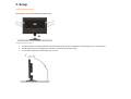
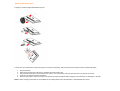
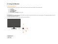
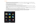
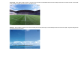
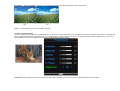
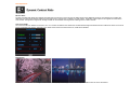
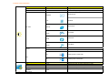
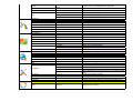
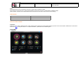
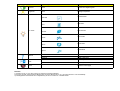
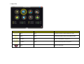
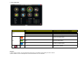
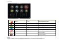
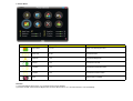
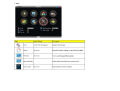
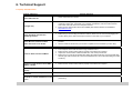
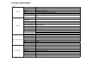
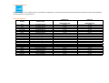
2230Fm User Manual
1. Preface
About This Guide
This guide describes the monitor's features, setup, and operation. lnformation in this document is subject to change without notice.
The sections are as follows:
•
•
•
•
•
•
•
Safety Instructions: lists safety information.
Setup: describes the initial setup process.
Using the Monitor: gives an overview of how to use the monitor.
Driver
Technical Support : provides tips and solutions for common problems.
Product Information: lists the technical specifications of the monitor.
Warranty Statement: Warranty Statement
National Conventions
The following subsections describe notational conventions used in this document.
Notes, Cautions, and Warnings
Throughout this guide, blocks of text may be accompanied by an icon and printed in bold type or in italic type. These blocks are notes, cautions, and warnings, and they are
used as follows:
NOTE: A NOTE indicates important information that helps you make better use of your computer system.
CAUTION: A CAUTION indicates either potential damage to hardware or loss of data and tells you how to avoid the problem.
WARNING: A WARNING indicates the potential for bodily harm and tells you how to avoid the problem.
Some warnings may appear in alternate formats and may be unaccompanied by an icon. In such cases, the specific presentation of the warning is mandated by regulatory
authority.
Product Registration
Please link www.aoc.com, select your country or region, log in Product Registration to register .
2. Safety Introduction
FCC Notice
FCC Class B Radio Frequency Interference Statement WARNING: (FOR FCC CERTIFIED MODELS)
NOTE: This equipment has been tested and found to comply with the limits for a Class B digital device, pursuant to Part 15 of the FCC Rules. These limits are designed to
provide reasonable protection against harmful interference in a residential installation. This equipment generates, uses and can radiate radio frequency energy, and if not
installed and used in accordance with the instructions, may cause harmful interference to radio communications. However, there is no guarantee that interference will not
occur in a particular installation. If this equipment does cause harmful interference to radio or television reception, which can be determined by turning the equipment off
and on, the user is encouraged to try to correct the interference by one or more of the following measures:
1.
2.
3.
4.
Reorient or relocate the receiving antenna.
Increase the separation between the equipment and receiver.
Connect the equipment into an outlet on a circuit different from that to which the receiver is connected.
Consult the dealer or an experienced radio/TV technician for help.
NOTICE :
1.
2.
3.
The changes or modifications not expressly approved by the party responsible for compliance could void the user's authority to operate the equipment.
Shielded interface cables and AC power cord, if any, must be used in order to comply with the emission limits.
The manufacturer is not responsible for any radio or TV interference caused by unauthorized modification to this equipment. It is theresponsibilities of the user to
correct such interference.
WEEE Declaration
Disposal of Waste Equipment by Users in Private Household in the European Union. (Europe only)
This symbol on the product or on its packaging indicates that this product must not be disposed of with your other household waste.Instead, it is your responsibility to
dispose of your waste equipment by handing it over to a designated collection point for the recycling of waste electrical and electronic equipment.The separate collection
and recycling of your waste equipment at the time of disposal will help to conserve natural resources and ensure that it is recycled in a manner that protects human health
and the environment. For more information about where you can drop off your waste equipment for recycling, please contact your local city office, your household waste
disposal service or the shop where you purchased the product .
HG Declaration
SAFETY: Lamp Disposal
LAMP(S) INSIDE THIS PRODUCT CONTAIN MERCURY AND MUST BE RECYCLED OR DISPOSED OF ACCORDING TO LOCAL, STATE OR FEDERAL LAWS. FOR
MORE INFORMATION, CONTACT THE ELECTRONIC INDUSTRIES ALLIANCE AT WWW.EIAE.ORG.
Precautions
WARNING: Use of controls, adjustments, or procedures other than those specified in this documentation may result in exposure to shock, electrical hazards,
and/or mechanical hazards.
Read and follow these precautions when connecting and using your computer monitor:
PRECAUTIONS
•
•
•
•
•
•
•
•
•
•
•
•
•
•
.
Do not use the monitor near water, e.g. near a bathtub, washbowl, kitchen sink, laundry tub, swimming pool or in a wet basement.
Do not place the monitor on an unstable cart, stand, or table. If the monitor falls, it can injure a person and cause serious damage to the appliance. Use only a cart
or stand recommended by the manufacturer or sold with the monitor. If you mount the monitor on a wall or shelf, use a mounting kit approved by the manufacturer
and follow the kit instructions.
Slots and openings in the back and bottom of the cabinet are provided for ventilation. To ensure reliable operation of the monitor and to protect it from overheating,
be sure these openings are not blocked or covered. Do not place the monitor on a bed, sofa, rug, or similar surface. Do not place the monitor near or over a
radiator or heat register. Do not place the monitor in a bookcase or cabinet unless proper ventilation is provided.
The monitor should be operated only from the type of power source indicated on the label. If you are not sure of the type of power supplied to your home, consult
your dealer or local power company.
The monitor is equipped with a three-pronged grounded plug, a plug with a third (grounding) pin. This plug will fit only into a grounded power outlet as a safety
feature. If your outlet does not accommodate the three-wire plug, have an electrician install the correct outlet, or use an adapter to ground the appliance safely. Do
not defeat the safety purpose of the grounded plug.
Unplug the unit during a lightning storm or when it will not be used for long periods of time. This will protect the monitor from damage due to power surges.
Do not overload power strips and extension cords. Overloading can result in fire or electric shock.
Never push any object into the slot on the monitor cabinet. It could short circuit parts causing a fire or electric shock. Never spill liquids on the monitor.
Do not attempt to service the monitor yourself; opening or removing covers can expose you to dangerous voltages and other hazards. Please refer all servicing to
qualified service personnel.
To ensure satisfactory operation, use the monitor only with UL listed computers which have appropriate configured receptacles marked between 100 - 240V AC,
Min. 5A.
The wall socket shall be installed near the equipment and shall be easily accessible.
For use only with the attached power adapter (Output 12Vdc) which have UL,CSA listed license(Only for monitors with power adapter).
Please make sure to clean the cabinet regularly with the provided cloth , you can use soft-cleanser to clean the stain , instead of severe spray cleanser which will
cauterize the monitor cabinet.
Dont leak liquid into monitor which will result in the damage of chassis or component. Please unplug before cleaning ,and do not scratch the screen with hard
things.
3. Setup
Setup the stand and base
Please setup or remove the base following below steps.
Adjusting Viewing Angle
•
•
•
For optimal viewing it is recommended to look at the full face of the monitor, then adjust the monitor's angle to your own preference.
Hold the stand so you do not topple the monitor when you change the monitor's angle.
You are able to adjust the monitor's angle from -5°to 20 °.
NOTE:
Do not touch the LCD screen when you change the angle. It may cause damage or break the LCD screen.
Attaching the Cables
Cable Connections On Back of Monitor and Computer
1. Power
2.HDMI
3. DVI
4. Analog
5. Audio
6. Earphone
7. USB
Turn off your computer before performing the procedure below.
1.
2.
3.
4.
5.
6.
Connect the power cable to the AC port on the back of the monitor.
Connect one end of the 15-pin D-Sub cable to the back of the monitor and connect the other end to the computer's D-Sub port.
(Optional ¨C Requires a video card with DVI port) - Connect one end of the 24-pin DVI cable to the back of the monitor and connect the other end to the
computer¡¯ s DVI port.
(Optional ¨C Requires a video card with HDMI port) - Connect one end of the HDMI cable to the back of the monitor and connect the other end to the computer¡¯ s
HDMI port.
Connect the audio cable to audio in port on the back of the monitor
Turn on your monitor and computer.
If your monitor displays an image, installation is complete. If it does not display an image, see Troubleshooting.
Attaching Wall Mounting Arm
Preparing to Install An Optional Wall Mounting Arm
This monitor can be attached to a wall mounting arm you purchase separately. Disconnect power before this procedure. Follow these steps:
1.
2.
3.
4.
5.
Remove the base.
Follow the manufacturer's instructions to assemble the wall mounting arm.
Place the wall mounting arm onto the back of the monitor. Line up the holes of the arm with the holes in the back of the monitor.
Insert the 4 screws into the holes and tighten.
Reconnect the cables. Refer to the user's manual that came with the optional wall mounting arm for instructions on attaching it to the wall.
Noted : VESA mounting screw holes are not available for all models, please check with the dealer or official department of AOC.
4. Using the Monitor
Setting the Optimal Resolution
The recommended resolution for this monitor is 1680 by 1050. To setup the monitor to this resolution, follow the steps below.
1.
2.
3.
4.
5.
6.
Click START.
Click SETTINGS.
Click CONTROL PANEL.
Double click DISPLAY.
Click SETTINGS.
Set the resolution SLIDE-BAR to 1680 by 1050.
External Controls
Press the power button to turn the monitor on or off. The other control knobs are located at front panel of the monitor (See Figure ). By changing these settings, the picture
can be adjusted to your personal preferences.
* The power cord should be connected.
* Press the power button to turn on the monitor. The power indicator will light up.
1
2
3
4
5
Eco mode / Up
Source(Auto) / Exit
Volume / Left
DCR / Right
Menu / Power
OSD Settings
•
•
•
•
•
•
•
•
•
•
•
Press the Menu (Power) button to activate the OSD window. Press left, right, up, down button to navigate through the functions. Once the desired function is
highlighted, press the Menu (Power) button to activate sub-menu .
In sub-menu, Press up, down button to navigate through the functions. Once the desired function is highlighted, press , button to button to change the setting.
Press Menu (Power) button to return to superior menu.
If you want to adjust any other function, repeat steps 1-2.
To exit OSD windows, select “exit” icon on main OSD, then press the Menu (Power) button .
OSD Lock Function: To lock the OSD, press and hold the Left button while the monitor is off and then press power button to turn the monitor on. To un-lock the
OSD - press and hold the Left button while the monitor is off and then press power button to turn the monitor on.
Eco Mode hot key ( ) : Press the Eco key continuously to select the Eco mode of brightness when there is no OSD ( Eco mode hot key may not be available in all
models).
Volume adjustment hot key : When there is no OSD , press Volume ( ) to active volume adjustment bar, press or to adjust volume ( Only for the models with
speakers).
DCR hot key ( ) : Press DCR key continuously to active or disable DCR function when there is no OSD.
Source hot key : When the OSD is closed, press Auto/Source button will be Source hot key function (Only for the models with dual or more inputs) .Press Source
button continuously to select the input source showed in the message bar , press Menu button to change to the source selected.
Auto configure hot key: When the OSD is closed, press Auto/Source button continuously about 2 second to do auto configure.
Press the Power button continuously about 2 second to turn off the monitor.
DCB Adjustment
What is DCB?
Dynamic Color Boost (DCB) is an advanced color adjustment technology. Through analyzing RGB signals, DCB creates more vivid and natural images to suit various color
environment needs. DCB has two types of color enhancers: “Color Boost” and “Picture Boost” .
DCC: Dynamic color control
ICM: Intelligent color management
1) How to use Color Boost?
Five color-enhancement settings: To accommodate various display needs, Color Boost also offers 5 different color enhancement modes: Full Enhance, Natural Skin,
Green Field, Sky Blue, and Auto-Detect. Please go to the fourth icon labeled “Color Boost” in the OSD menu and select one of the five settings you desire to be turned on.
Full Enhance: When "Full Enhance" is turned on, the color saturation of the entire screen is fully enriched, thus all colors become more vibrant.
Nature Skin: When "Natural Skin" is turned on, the red and yellow colors are enriched automatically, thus presents human skin with more natural and truer colors.
"Natural Skin" setting is ideal for viewing human portrait and detailed skin texture.
Green Field: When "Green Field" is turned on, the green color is enriched so that football field and mountain landscape would look more natural and fresh. “Green Field”
setting is ideal for watching mountain scenery and outdoor sports.
Sky Blue: When"Sky Blue" is turned on, the color blue is being fine-tuned so that the sky or ocean landscape will look more vivid and in-depth. "Sky Blue" setting is ideal
for viewing sky and ocean images.
Auto Detect:
Demo:
When “Auto Detect” is turned on, every pigment will be detected and self-adjusted to render a lively picture.
Screen divided into two for demonstration purposes.
2) How to use Picture Boost?
Users can change the color settings of a self-selected zone on the screen. The size and position of the selected zone can also be adjusted. "Picture Boost" is located in the
fifth icon labeled "Picture Boost" in the OSD menu. Turn on "Bright Frame" to select a zone on the screen to be enhanced. Please note when adjust or turn on any one of
the DCB features, the rest of color settings including DCR will be disabled or return to default.
Disclaimer: DCB aftereffects are subject to the resolution and quality of the display content, hence may look different than the above illustrations.
DCR Adjustment
What is DCR?
Dynamic Contrast Ratio (DCR) auto adjusts the brightness of the screen so users can see the darker areas of the displayed content in more depths. By increasing the
darkness of the dark areas and the brightness of the bright areas, contrast ratio is uplifted to exceed 10000:1. DCR value varies subject to the original CR values of the
LCD module. The higher the original CR, the higher DCR can be achieved. DCR is great for watching movie or video contents.
How to Use DCR?
Go to the first OSD icon labeled "Luminance", turn on or off DCR as desires. DCR boosts the contrasts between lightness & darkness and enables the viewer to see more
layers and details of the picture, especially in the darker areas. Please note when DCR is on, DCB will be disabled.
DCR Demos:
Disclaimer: DCR aftereffects are subject to the resolution and quality of the display content, hence may look different than the above illustrations.
Function Control Illustration
Luminance
Brightness
Contrast
Adjust Range
0-100
0-100
Standard
Text
Eco mode
Internet
Game
Movie
Sports
Description
Backlight Adjustment
Contrast from Digital-register.
Standard Mode
Text Mode
Internet Mode
Game Mode
Movie Mode
Sports Mode
Gamma1
Gamma2
Gamma3
Adjust to Gamma1
Adjust to Gamma 2
Adjust to Gamma 3
Off
Disable dynamic contrast ratio
On
Enable dynamic contrast ratio
Image Setup
Clock
Phase
H.Position
0-100
0-100
0-100
V.Position
0-100
Adjust picture Clock to reduce Vertical-Line noise.
Adjust Picture Phase to reduce Horizontal-Line noise
Adjust the verticalposition of the picture.
Adjust the horizontal position of the picture.
Gamma
DCR
Color Temp.
Warm
Normal
Cool
sRGB
User
Color Boost
Full Enhance
Nature Skin
Green Field
Sky-blue
AutoDetect
Demo
Picture Boost
Frame Size
Brightness
Contrast
Hue
Saturation
Position
Bright Frame
OSD Setup
H.Position
V.Position
Timeout
Transparence
Language
Extra
Input Select
Red
Green
Blue
Recall Warm Color Temperature from EEPROM.
Recall Normal Color Temperature from EEPROM.
Recall Cool Color Temperature from EEPROM.
Recall SRGB Color Temperature from EEPROM.
Red Gain from Digital-register
Green Gain Digital-register.
Blue Gain from Digital-register
on or off
on or off
on or off
on or off
on or off
on or off
Disable or Enable Full Enhance Mode
Disable or Enable Nature Skin Mode
Disable or Enable Green Field Mode
Disable or Enable Sky-blue Mode
Disable or Enable AutoDetect Mode
Disable or Enable Demo
14-100
0-100
0-100
0-100
0-100
H. position
V.position
on or off
Adjust Frame Size
Adjust Frame Brightness
Adjust Frame Contrast
Adjust Frame Hue
Adjust Frame Saturation
Adjust Frame horizontal Position
Adjust Frame vertical Position
Disable or Enable Bright Frame
0-100
0-100
5-120
0-100
Adjust the verticalposition of OSD
Adjust the horizontal position of OSD
Adjust the OSD Timeout
Adjust the transparence of OSD
Select the OSD language
Auto
Analog
Digital
Select to Auto Detect input signal
Select Analog Sigal Source as Input
Select Digital Sigal Source as Input
Select HDMI sigal source as input (Only for the models with HDMI
input)
Auto adjust the picture to default
Select wide or 4:3 format for display
Turn ON/OFF DDC-CI Support
Show the information of the main image and sub-image source
6500K
7300K
9300K
HDMI
Auto Config
Image Ratio
DDC-CI
Information
Reset
yes or no
wide or 4:3
yes or no
Reset
yes or no
Reset the menu to default
Exit
Exit
Exit the main OSD
Notes:
1)If the product has only one signal input, the item of "Input Select" is disable to adjust.
2)If the product screen size is 4:3 or input signal resolution is wide format, the item of "Image Ratio" is disalbe to adjust.
3)One of DCR, Color Boost, and Picture Boost functions is active, the other two function is turned off accordingly.
LED Indicators
Status
Full Power Mode
Active-off Mode
LED Color
Green or Blue
Orange or red
How to use i-Menu software
Installation
Welcome to use “i-Menu” software by AOC. i-Menu makes it easy to adjust your monitor display setting by menus on the screen instead of OSD button on the monitor.
Please click here to setup the software. To complete installation , please follow the installation guide .
Using “i-Menu”
1. Luminance
Luminance
Adjust Range
Description
Contrast
0-100
Contrast from Digital-register.
Brightness
0-100
Backlight Adjustment
Standard
Text
Eco mode
Internet
Game
Movie
Sports
Gamma
DCR
Reset
Standard Mode
Text Mode
Internet Mode
Game Mode
Movie Mode
Sports Mode
Gamma1
Gamma2
Gamma3
Adjust to Gamma1
Adjust to Gamma 2
Adjust to Gamma 3
Off
Disable dynamic contrast ratio
On
Enable dynamic contrast ratio
Reset the current page
Remarks:
1) If DCR is set to “on”, the other 4 items of Luminance cannot be adjusted.
2) If anyone of DCR, Color Boost and Bright Frame of Picture Boost is set to “on”, the others are set to “off” automatically.
3) The Brightness and Contrast can be adjusted only when Eco-mode is on “standard mode”.
2. Image setup
Image Setup
Adjust Range
Description
Clock
0-100
Adjust picture Clock to reduce Vertical-Line noise.
Phase
0-100
Adjust Picture Phase to reduce Horizontal-Line noise
H.Position
0-100
Adjust the verticalposition of the picture.
V.Position
0-100
Adjust the horizontal position of the picture.
Reset
Reset the current page
3. Color Temperature
Color Temp.
Preset
User
Reset
Adjust Range
Warm
Normal
Cool
sRGB
Description
Recall Warm Color Temperature from EEPROM.
Recall Normal Color Temperature from EEPROM.
Recall Cool Color Temperature from EEPROM.
Recall SRGB Color Temperature from EEPROM.
Red
Red Gain from Digital-register
Green
Green Gain Digital-register.
Blue
Blue Gain from Digital-register
Reset the menu to default
Remarks:
1) When “User” is chosen, you can change the monitor color to your desired color by setting the value of R-G-B.
2) When “sRGB” is chosen, the Brightness, Contrast and Gamma can not be adjusted.
4. Color Boost
Color Boost
Adjust Range
Description
Full Enhance
on or off
Disable or Enable Full Enhance Mode
Nature Skin
on or off
Disable or Enable Nature Skin Mode
Green Field
on or off
Disable or Enable Green Field Mode
Sky-blue
on or off
Disable or Enable Sky-blue Mode
AutoDetect
on or off
Disable or Enable AutoDetect Mode
Demo
Disable or Enable Demo
Reset
Reset the menu to default
Remarks:
1) There is only one item can be set to “on” except Demo. If you set any item to “on”, the others are changed to “off” automatically.
2) If anyone of DCR, Color Boost and Bright Frame of Picture Boost is set to “on”, the others are set to “off” automatically.
5. Picture Boost
Picture Boost
Adjust Range
Description
Bright Frame
on or off
Disable or Enable Bright Frame
Frame Size
14-100
Adjust Frame Size
Brightness
0-100
Adjust Frame Brightness
Contrast
0-100
Adjust Frame Contrast
H. position
0-100
Adjust Frame horizontal Position
V.position
0-100
Adjust Frame vertical Position
Reset
Reset the menu to default
Remarks:
1) Only when Bright Frame is set to “on”, the other 5 items can be adjusted.
2) If anyone of DCR, Color Boost and Bright Frame of Picture Boost is set to “on”, the others are set to “off” automatically.
6. Setting
7. Extra
8. Help
On this page, you can find the information of the monitor . Welcome to link our website and send email to us if you have any problem.
Compatibility :
i-Menu supports major graphic cards of ATI, Nvidia, Intel, VIA(S3). Please contact with us if your graphic card was not supported i-Menu software.
DMP Function(
(Digital Media Player)
)
Pls follow up the steps below and start your DMP function .
1 , Input Interface:
1) 4 in 1 memory card x1: Support SD / MMC / MS / xD memory cards
2) USB host
2, Support file format :
Photo : *.jpg, *.bmp, *.png, *.gif *.tiff
Audio : *.MP3, *.WMA , *.WAV
Video : *.mpg, *.dat, *.avi, *.rm , *.rmvb
3, Operation guide :
1) , Key button Introduction :
: Sel –
: Sel +
: Exit
: Enter / Source
2)
Operation guide with key button
•
•
•
•
•
•
•
•
•
•
Turn on the monitor .
Incert one of the cards (SD/MS/MMC/XD) into the 4-in-1 slot or USB Host .
press button to activate the OSD source menu .
press button continuously untill DMP function is selected , then press the Power button to enter into DMP interface .
In DMP main interface, press or for function selection .
Press button to enter into the sub-menu for input selection .
Press button to enter into the file list .
Press or button to choose your favorable content .
Press button for playing confirmation
Press button for the superior menu return
•
If you want to see any other function, repeat the above steps .
•
In DMP interface , press button to activate the OSD source menu , sellect the other source (except DMP) ,then press the Power button for DMP exit
confirmation .
When the DMP is playing , press button to activate Information Bar , and choose the function listed for adjustment .
•
5. Drivers
Windows 2000
1. Start Windows® 2000
2. Click on the 'Start' button, point to 'Settings', and then click on 'Control Panel'.
3. Double click on the 'Display' Icon.
4. Select the 'Settings' tab then click on 'Advanced...'.
5. Select 'Monitor'
- If the 'Properties' button is inactive, it means your monitor is properly configured. Please stop installation.
- If the 'Properties' button is active. Click on 'Properties' button. Please follow the steps given below.
6. Click on 'Driver' and then click on 'Update Driver...' then click on the 'Next' button.
7. Select 'Display a list of the known drivers for this device so that I can choose a specific driver', then click on 'Next' and then click on 'Have disk...'.
8. Click on the 'Browse...' button then select the appropriate drive F: ( CD-ROM Drive).
9. Click on the 'Open' button, then click on the 'OK' button.
10. Select your monitor model and click on the 'Next' button.
11. Click on the 'Finish' button then the 'Close' button.
If you can see the 'Digital Signature Not Found' window, click on the 'Yes' button.
Windows ME
1. Start Windows® Me
2. Click on the 'Start' button, point to 'Settings', and then click on 'Control Panel'.
3. Double click on the 'Display' Icon.
4. Select the 'Settings' tab then click on 'Advanced...'.
5. Select the 'Monitor' button, then click on 'Change...' button.
6. Select 'Specify the location of the driver(Advanced)' and click on the 'Next' button.
7. Select 'Display a list of all the drivers in a specific location, so you can choose the driver you want', then click on 'Next' and then click on 'Have Disk...'.
8. Click on the 'Browse...' button, select the appropriate drive F: ( CD-ROM Drive) then click on the 'OK' button.
9. Click on the 'OK' button, select your monitor model and click on the 'Next' button.
10. Click on 'Finish' button then the 'Close' button.
Windows XP
1. Start Windows® XP
2. Click on the 'Start' button and then click on 'Control Panel'.
3. Select and click on the category 'Printers and Other Hardware'
4. Click on the 'Display' Item.
5. Select the 'Settings' tab then click on the 'Advanced' button.
6. Select 'Monitor' tab
- If the 'Properties' button is inactive, it means your monitor is properly configured. Please stop installation.
- If the 'Properties' button is active, click on 'Properties' button.
Please follow the steps below.
7. Click on the 'Driver' tab and then click on 'Update Driver...' button.
8. Select the 'Install from a list or specific location [advanced]' radio button and then click on the 'Next' button.
9. Select the 'Don't Search. I will choose the driver to install' radio button. Then click on the 'Next' button.
10. Click on the 'Have disk...' button, then click on the 'Browse...' button and then select the appropriate drive F: (CD-ROM Drive).
11. Click on the 'Open' button, then click the 'OK' button.
12. Select your monitor model and click on the 'Next' button.
- If you can see the 'has not passed Windows® Logo testing to verify its compatibility with Windows® XP' message, please click on the 'Continue Anyway' button.
13. Click on the 'Finish' button then the 'Close' button.
14. Click on the 'OK' button and then the 'OK' button again to close the Display_Properties dialog box.
Windows Vista
1.
Start Windows® Vista
2. Click the Start button; select and click on 'Control Panel'.
3. Select and click on 'Hardware and Sound'
4. Choose 'Device Manager' and Click on 'Update device drivers'.
5. Select 'Monitor' and then right click on 'Generic PnP Monitor'.
6. Click on 'Update Driver Software'.
7. Select 'Browse my computer for driver software'.
8. Click the 'Browse'button and choose the drive in which you've placed the disk. Example:(CD-ROM Drive:\\Lcd\PC\drivers\).
9. Click the 'Next' button.
10. Wait few minutes for installing the driver, and then click 'Close' button.
6. Technical Support
Frequently Asked Questions
Problem & Question
•
Power LED Is Not ON
•
No Plug & Play
Picture Is Fuzzy & Has Ghosting
Shadowing Problem
Picture Bounces, Flickers Or Wave
Pattern Is Present In The Picture
•
Possible Solutions
Make sure the power button is ON and the Power Cord is properly connected to a grounded
power outlet and to the monitor.
In order for the Plug & Play feature of the monitor to work, you need a Plug & Play compatible
computer & video card. Check with your computer manufacturer. Also check the monitor's
video cable and make sure none of the pins are bent.
Make sure the AOC Monitor Drivers are installed (AOC Monitor Drivers are available at :
http://www.aoc.com)
•
•
Adjust the Contrast and Brightness Controls.
Make sure you are not using an extension cable or switch box. We recommend plugging the
monitor directly to the video card output connector on the back of your computer.
•
Move electrical devices that may cause electrical interference as far away from the monitor as
possible.
Use the maximum refresh rate your monitor is capable of at the resolution your are using.
•
•
•
•
•
•
The Computer Power Switch should be in the ON position.
The Computer Video Card should be snugly seated in its slot.
Make sure the monitor's video cable is properly connected to the computer.
Inspect the monitor's video cable and make sure none of the pins are bent.
Make sure your computer is operational by hitting the CAPS LOCK key on the keyboard while
observing the CAPS LOCK LED. The LED should either turn ON or OFF after hitting the CAPS
LOCK key.
•
•
Inspect the monitor's video cable and make sure that none of the pins arebent.
Make sure the monitor's video cable is properly connected to the computer.
Screen image is not centered or sized
properly
•
Adjust H-Position and V-Position or press hot-key (AUTO).
Picture has color defects (white does not
look white)
•
Adjust RGB color or select color temperature
•
Use win 95/98/2000/ME/XP shut-down mode Adjust CLOCK and FOCUS or perform hot-key
(AUTO-key )
Monitor Is Stuck In Active Off-Mode"
Missing one of the primary colors (RED,
GREEN, or BLUE)
Horizontal or vertical disturbances on the
screen
7. Product Information
Specifications
Model number
2230Fm
Driving system
TFT Color LCD
Viewable Image Size
558.68mm diagoanl
Pixel pitch
0.282mm(H) x 0.282mm(V)
LCD Panel
Video
R, G, B Analog lnterface & Digital Interface, HDMI
Separate Sync.
H/V TTL
Display Color
16.7M Colors
Dot Clock
165 MHz
Horizontal scan range
31 kHz - 83 kHz
Horizontal scan
473.76mm
Size(Maximum)
Vertical scan range
56 Hz - 76 Hz
Vertical scan Size(Maximum) 296.1mm
Optimal preset resolution
1680 x 1050 (60 Hz)
Highest preset resolution
1680 x 1050 (60 Hz)
Resolution
Plug & Play
VESA DDC2B/CI
Input Connector
D-Sub & DVI-D,HDMI
Input Video Signal
Analog: 0.7Vp-p(standard), 75 OHM, Positive & DVI-D,HDMI
Power Source
100~240VAC, 50/60Hz
Active < 60 W
Power Consumption
Standby < 2 W
Speakers
2 x 2W
Connector Type
15-pin Mini D-Sub & 24 pin DVI-D, 19 pin HDMI
Signal Cable Type
Detachable
Dimensions & Weight:
Height (with base)
439 mm
Physical Characteristics
Width
358 mm
Depth
210 mm
Weight (monitor only)
5.2kg
Weight (with packaging)
6.7 kg
Temperature:
Operating
0° to 40°
Non-Operating
-20°to 60°
Humidity:
Environmental
Operating
10% to 85% (non-condensing)
Non-Operating
5% to 80% (non-condensing)
Altitude:
Operating
0~ 3000m (0~ 10000 ft )
Non-Operating
0~ 5000m (0~ 15000 ft )
EPA ENERGY STAR ®
ENERGY STAR® is a U.S. registered mark. As an ENERGY STAR® Partner, AOC International (Europe) GmbH has determined that this product meets the ENERGY
STAR® guidelines for energy efficiency.
Preset Display Modes
STAND
RESOLUTION
VGA
VGA
VGA
Dos-mode
Dos-mode
SVGA
SVGA
SVGA
SVGA
SVGA
XGA
XGA
XGA
XGA
XGA
XGA
XGA
SXGA
SXGA
SXGA
WSXGA
WSXGA+
640¡Á480 @60Hz
640¡Á480 @72Hz
640¡Á480 @75Hz
720¡Á400 @70Hz
640¡Á400 @71Hz
800¡Á600 @56Hz
800¡Á600 @60Hz
848x480@60Hz
800¡Á600 @72Hz
800¡Á600 @75Hz
1024¡Á768 @60Hz
1024¡Á768 @70Hz
1024¡Á768 @75Hz
1024¡Á768 @75Hz
1280¡Á768 @60Hz
1280¡Á768 @60Hz
1280¡Á768 @75Hz
1280¡Á1024 @60Hz
1280¡Á1024 @70Hz
1360x768@60Hz
1680¡Á1050 @60Hz
1680x1050@60Hz
HORIZONTAL
VERTICAL
FREQUENCY(kHZ)
31.469
37.861
37.500
31.469
31.469
35.156
37.879
31.020
48.077
46.875
48.363
56.476
60.023
60.241
47.776
47.396
60.289
63.981
74.882
47.712
65.290
65.290
FREQUENCY(Hz)
59.940
72.809
75.000
70.087
70.087
56.250
60.317
60.000
72.188
75.000
60.004
70.069
75.029
74.927
59.870
59.995
74.893
60.020
69.853
60.015
59.954
59.954
Pin Assignments
Pin Number
1
2
3
4
5
6
7
8
9
10
11
12
13
14
15
Pin No.
1
2
3
4
5
6
7
8
15-Pin Side of the Signal Cable
Video-Red
Video-Green
Video-Blue
N.C.
Detect Cable
GND-R
GND-G
GND-B
+5V
Ground
N.C.
DDC-Serial data
H-sync
V-sync
DDC-Serial clock
Signal Name
TMDS Data 2TMDS Data 2+
TMDS Data 2/4 Shield
TMDS Data 4TMDS Data 4+
DDC Clock
DDC Data
N.C.
Pin No.
9
10
11
12
13
14
15
16
Signal Name
TMDS Data 1TMDS Data 1+
TMDS Data 1/3 Shield
TMDS Data 3TMDS Data 3+
+5V Power
Ground(for+5V)
Hot Plug Detect
Pin No.
17
18
19
20
21
22
23
24
TMDS
TMDS
TMDS
TMDS
TMDS
TMDS
TMDS
TMDS
Signal Name
Data 0Data 0+
Data 0/5 Shield
Data 5Data 5+
Clock Shield
Clock +
Clock -
Pin No.
1
2
3
4
5
6
7
8
Signal Name
TMDS Data 2+
TMDS Data 2 Shield
TMDS Data 2
TMDS Data 1+
TMDS Data 1Shield
TMDS Data 1
TMDS Data 0+
TMDS Data 0 Shield
Pin No.
9
10
11
12
13
14
15
16
TMDS
TMDS
TMDS
TMDS
Signal Name
Data 0
Clock +
Clock Shield
Clock
Pin No.
17
18
19
Signal Name
DDC/CEC Ground
+5V Power
Hot Plug Detect
CEC
Reserved (N.C. on device
SCL
SDA
Plug and Play
Plug & Play DDC2B Feature
This monitor is equipped with VESA DDC2B capabilities according to the VESA DDC STANDARD. It allows the monitor to inform the host system of its identity and,
depending on the level of DDC used, communicate additional information about its display capabilities.
The DDC2B is a bi-directional data channel based on the I2C protocol. The host can request EDID information over the DDC2B channel.
8. Warranty Statement