1
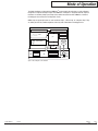
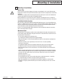
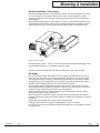
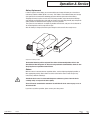
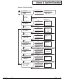
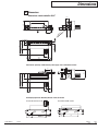
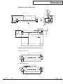
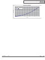
Instruction manual red-y compact series
compact regulator GCR
compact all-in GCA
compact meter GSM & compact switch GCS
Vögtlin Instruments AG – flow technology
Langenhagstrasse 1 | 4147 Aesch (Switzerland)
Phone +41 (0)61 756 63 00 | Fax +41 (0)61 756 63 01
www.voegtlin.com | [email protected]
Instruction manual red-y compact series
compact meter GCM
compact regulator GCR
compact switch GCS
compact all-in GCA
Copyright © 2005 Vögtlin Instruments AG, Switzerland
Version: compact_E4_0
Editing: Daniel Walliser, Christian Mahrer
Design: Michael Huber
You will find up-to-date information on our products on the Internet at www.red-y.com
Vögtlin Manual
Version
red-y compact series compact_E4_0
Chapter
Page
00
2
Table of Contents
01 Introduction
4
Operator Benefits
Service and Quality
Guarantee
02 Mode of Operation
6
Measurement principle
CMOS Technology
03 Technical Information
8
General Specifications of the Device
Mechanical Specifications
Electrical Data
Display
Measurement Ranges
Connector Assignment
Conversion Factors for other Gases
Loss of Pressure
Temperature Compensation
Pressure Compensation
04 Mounting & Installation
11
General Tips
Installation Position/Location
Mechanical Piping
Electrical Connection / Power Supply
Gas Supply
05 Operation & Service
13
Warm-Up Time
Zero Point Check
Service
Cleaning in the Event of Soiling
Replacement of Battery
Returns
06 Alarm & Switch Function
15
Individual Functions in Detail
Diagram of Function Settings
Alarm situations
07 Totalizer
18
General
Function
Reset
08 Dimensions
09 Annex
19
21
Drop of Pressure
Type Code
Contamination Statement
Vögtlin Manual
Version
red-y compact series compact_E4_0
© Vögtlin Instruments AG
Chapter
Page
00
3
Introduction
01 Welcome
With red-y you get the latest, most modern CMOS sensor technology. CMOSensTM is a technology
label and stands for a modern process in which the sensor and the signal processing are combined
on a highly integrated chip.
This manual will familiarize you with the installation and operation of your red-y. We therefore ask
you to read this manual carefully and to contact your sales partner with any questions or doubts.
We have prepared this manual very carefully in order provide you with appropriate and precise
information and instructions. However, no liability is assumed for any errors.
Operator Benefits
Ultimately, a technology only represents a means to an end. Therefore all of our efforts are aimed at
the requirements and wishes of the user of this instrument and his measurement and regulation
tasks:
- Battery-operated thermal mass flow meters
- Optional alarm function
- Compact, easy-to-install measurement or regulation unit
- CE approved
- Easy maintenance and service
- Easy expansion of functionality
- 3-year guarantee
- Top performance in response, dynamics and accuracy
- Matching options and accessories
Service and quality
We continuously improve the quality of our products and services. Only with use does it ultimately
become clear whether the right product has been selected. Thus, we attempt not only to propagate
good service and high quality, but to live it every day.
Guarantee
The guarantee for red-y for gasflow products extends to material defects and production flaws. The
guarantee maximum is the replacement of the equipment at no cost. Claims are omitted in the case
of inappropriate use, external effects in general, excessive heat or dropping.
We are always grateful for information on existing defects, for suggestions for improvements, and
for critiques.
Vögtlin Manual
Version
red-y compact series compact_E4_0
© Vögtlin Instruments AG
Chapter
Page
01
4
Introduction
Tips and Warnings
Before putting the instrument into use, these operating instructions should be read thoroughly.
Improper use, errors for lack of understanding and the consequences arising from this, can lead to
the destruction of the instrument or even the endangerment of personnel.
The equipment should be put into operation and serviced by appropriately qualified personnel only.
The proper handling of the products is an absolute requirement for its trouble-free operation.
Electrostatic discharges can destroy the electronic components of this measurement and regulation
unit.
Vögtlin Manual
Version
red-y compact series compact_E4_0
© Vögtlin Instruments AG
Chapter
Page
01
5
Mode of Operation
02 A bit of theory
Measuring principle
The measuring principle of thermal flow measurement is perfectly suited for the measurement of
gas flows. One of the significant advantages is that the measurement is largely independent of
pressure and temperature. By contrast to volumetric principles, pressure and temperature do not
have to be additionally measured. Although the principle yields mass as a measurement result (e.g.
g/min), most devices are calibrated to standard volumes (e.g. ln/min). One possible explanation is
the fact that the comparability of the measurement results with other principles is given with this.
Since the thermal flow measurement depends on the type of gas, in addition to the specific heat ,
the standard density (0°C, 1,01325 bar a) for the conversion to standard volume is also used.
With all design options of the measuring principle, there is always a heater and one or more
temperature-measurement points and the gasflow draws heat from the heater.
With the red-y mass flow meter, a constant heating power ensures a temperature difference that is
directly proportional to the gas flow rate. In the flume, a temperature measurement is followed by a
heater, and then a temperature measurement again. The figure below illustrates this process. If the
flow rate=0, the heater H uniformly distributes the heat, for which the temperature difference T1-T2
equals zero. Two effects occur with the flow rate that lead to a temperature difference: First, the
temperature sensor T1 at the entrance detects a lower temperature. This happens because of the
cooling of the entering gas, which theoretically drops to the ambient temperature respective of gas.
Secondly, the gas flowing over the heater carries heat to the temperature sensor T2, located after
the heater, and thus increases this temperature. The temperature difference is in direct proportion to
the mass flow.
T2
T1
H
ΔT
ΔT
T2
flow
Tenvironment
T1
Figure 2: Schematic illustration of how thermal mass measurement functions
CMOS Technology
Red-y measurement and regulation units feature a new basic technology that sets standards for
maximum precision sensor systems. The fusion of a semi-conductor chip with sensor technology
results in a highly integrated system solution that is impressive for its excellent sensor precision, as
well as digital intelligence and reliability.
The most notable advantages to the customer are the outstanding precision of the sensor, the rapid
response time and a dynamic measuring range that no system has attained up until now.
Thanks to the compact single chip design, CMOSensTM-based sensors are extremely resistant to
electromagnetic interference (EMI), a significant technical advantage of this ultra modern sensor
technology.
With CMOSensTM, the sensor element, amplifier and A/D converter form a unit on the same silicon
chip.
Vögtlin Manual
Version
red-y compact series compact_E4_0
© Vögtlin Instruments AG
Chapter
Page
02
6
Mode of Operation
The digital intelligence linked with the CMOSensTM sensor permits the emission of a fully calibrated,
temperature-compensated output signal. The CMOSensTM ‘intelligence’ integrated onto the chip thus
facilitates an extremely simple processing of the emitted measurement data. CMOS is a standard
technology for the manufacture of integrated circuits.
CMOS chips are generally known as ‘semi-conductor chips’, ‘silicon chips’ or ‘computer chips’. They
are widely used in PCs, mobile telephones and many other information technology devices.
Battery
Power Supply / Alarm contact
or 20.0 LCD
NEXT
SPI
μP
Push-buttons
SET
Sensor μP
EEPROM
Manual
Control
Valve
Sensor
Flow rectifier
Flow divider
Figure 2: Block diagram of the hardware
Vögtlin Manual
Version
red-y compact series compact_E4_0
© Vögtlin Instruments AG
Chapter
Page
02
7
Technical Information
03 Technical Information
General Specifications of the Device
Accuracy
Dynamics
Standard measurement range
Repeatability
Long-term stability
Temperature coefficient
Pressure coefficient
Operating pressure
Temperature range
Leak rate
Heat-up period
+/- 1% of full scale
2 – 100 % within the specification
Signal suppression less than 2% of full scale
+/- 1% from measurement value
< 1% from measurement value / year
< 0,2% / bar (typical N2)
up to 10 bar g
0 – 50 °C
1 x 10⁻⁸ mbars l/s He
30 minutes for maximum accuracy
Mechanical specifications
Materials
Design Code A (Alu)
Design Code S (high-grade steel)
Sensor
Sealing material
Process connection
Protection category
Aluminum, nickelized brass, stainless steel
Stainless steel
PBT, epoxy
FKM, optional EPDM or PTFE
Inside thread G1/4", G1/2” on both sides,
optional with compression fittings
(see accessory annex)
IP-50, front side IP-65
Electrical data
Supply voltage
Battery operation
External feed
With battery module, useful life ca. 2 years
+ 24 V dc +/- 10%
Alarm contact (switch and all-in)
Function
Max voltage
Max current
Floating change-over contact
24 Vdc
1A
Display
LC Display
Vögtlin Manual
Version
red-y compact series compact_E4_0
© Vögtlin Instruments AG
For present flow rate with bar graph and
the corresponding unit.
Configuration parameters for the alarm function
Chapter
Page
03
8
Technical Information
Measurement Ranges
Red-y measurement and control devices are supplied with standard measurement ranges for air. As
an option, the devices are available with individual measurement ranges and, upon request, can be
calibrated with other gases.
Standard Measurement Ranges
Code
Meas. range
A4
A5
B4
B5
200
500
2000
5000
Unit
mln/min
mln/min
mln/min
mln/min
Code
Meas. range
Unit
C4
C5
D3
D4
20
50
100
200
ln/min
ln/min
ln/min
ln/min
Connector Assignment
Instruments with the switch or external power supply are fitted with a cable (2m length) with the
following assignment:
Color Assignment
Color
Assignment
white
brown
grenn
yellow
grey
pink
blue
red
AL1 normal open
not assigned
not assigned
not assigned
+ 24 Vdc
0 Vdc
AL1 common
AL 1 normal closed
Conversion Factors for other Gases
Every instrument is fully and automatically calibrated on an ultra modern calibration system. The
internal conversion to the defined medium is done according to the application. Should you change
the mass medium, this may be corrected via conversion factors.
For this, contact your Insentys sales partner. Depending on the medium, these conversion factors
generate an additional measurement error.
Note
In the case of plant calibration with a gas other than air, an increased zero offset may be displayed
when the device is not operated with the calibrated gas.
Pressure Loss
The thermal mass flow meters feature little pressure loss. This essentially depends upon the
medium, operating pressure and the flow rate. In the annex (chapter 08/page 19) you will find a
table that shows the typical course of pressure loss in air, 20°C, 1,013 bar a for the three
measurement devices. The pressure loss for other gases can be calculated using the formula.
ΔPrequired = ΔP ×
ρ required
1.250
Please note that pipes that are two small and unsuitable fittings are often the cause of excessive
pressure loss in the system.
For trouble-free operation, devices with manual control valve require a certain pressure differential,
which is specified on the nameplate.
Vögtlin Manual
Version
red-y compact series compact_E4_0
© Vögtlin Instruments AG
Chapter
Page
03
9
Technical Information
Temperature Compensation
Thermal mass flow meters measure the flow of gases to a large extent independent on pressure
and temperature. Varying temperatures are automatically compensated by the measurement device.
The sensor measures gas temperature and automatically calculates a correction value using a
three-dimensional value table.
Pressure Compensation
With the calibration, the operating pressure specified with the order is also taken into consideration.
With pressure changes, an additional error can occur. Please note that the operation of the manual
control valve cannot be guaranteed if the pressure differential is too low or too high.
Vögtlin Manual
Version
red-y compact series compact_E4_0
© Vögtlin Instruments AG
Chapter
Page
03
10
Mounting & Installation
04 Mounting & Installation
General Tips
Check the packet for external damage and contact us immediately in the case of visible damage.
Compare the contents of the packet with the delivery slip and check for completeness and technical
compliance.
This product is a high-precision measuring instrument. We advise you to select the installation site
carefully and to follow the instructions and suggestions below.
Before installation, be sure that the data on the nameplate corresponds to the use, and that the
maximum pressure occurring in the system are lower than the specified test pressure of the device.
Installation Position/Location
We recommend a horizontal installation position. With higher pressure(> 5 bars), depending on the
medium, an additional offset error can occur with a vertical installation position. Check that no heat
sources or electrical sources with strong emissions are found near the measuring device. Avoid
constant vibrations or other disturbing mechanical effects (stress).
If there is a risk of fluid backflow during malfunction, then you should not mount the measuring
device at the lowest point of the pipe.
Mechanical Pipes
The pipe work is very important, and this is often underestimated. Inlet paths, dead volume of the
correct amount, proper grounding, clean pipes and leak-free connections have a decisive effect on
the quality of the measurement.
Be sure that the piping used is absolutely clean.
Use suitable pipe materials (compressive strength, durability).
With permanent pipes, it is also recommended that the device be fixed with the mounting holes
provided for this.
Avoid, when possible, a 90° angle directly at the inlet. If there is no other possibility,
consult your sales partner.
Use appropriate fittings, which are preferably sealed with o-rings on the front side against
the body of the device. Please do not hold on the housing while tightening the fittings.
Never use liquid sealant! If it has not hardened, it can spread all through the measuring device
during flow.
Optimize the pipe length between pressure reducing unit and flow meter. A certain dead volume
must be available with high flow rates in particular. The pipe diameter must likewise be adapted
to the flow rate. Pipe sections that are too small cause high pressure loss and can impair the
operation of the device.
Check the piping for any leaks.
The measuring devices have a flow rectifier. Nevertheless, with high flow rates (> 50 ln/min),
we recommend that you install an inlet path (10 times pipe diameter).
With critical applications (e.g. consumption metering with gas supply), we recommend the
installation of a bypass system with which you can continue to draw gas in the case of service
or repairs.
Vögtlin Manual
Version
red-y compact series compact_E4_0
© Vögtlin Instruments AG
Chapter
Page
04
11
Mounting & Installation
Electrical Connection / Power Supply
With the battery-operated devices, mount the battery module. Then the measuring device is ready
for use. The useful life of the battery module is about 2 years, but this depends on use. With
constantly changing flow rates, the useful life may be shorter. We advise you to use only original
battery modules.
With the external power supply and alarm options, you receive a connector cable with loose ends.
The assignment is printed on the cable. You have the option of turning the cable outlet by 180º. To
do this, you open the cover in back by hand and turn the plastic block to the desired direction.
Turning the cable outlet by 180°
The supply voltage must be + 24 Vdc (+/-10%) and have the lowest possible residual ripple. Please
note that voltage drops may occur with longer connecting cables.
Likewise, be aware of possible earth loops when you ground electrically conductive pipes.
Gas Supply
We recommend that you pay close attention to the gas supply line. Contamination in the form of
water, oil or dust are harmful to any measurement principle. Particularly in the case of air supply
with compressor systems, cleanliness cannot always be guaranteed. In case of doubt, install the
appropriate filter. If use-related backflows are to be expected, this filter should also be installed at
the outlet. Please monitor possible pressure loss due to the filter elements.
The gas supply should be oversized and have the capacity of at least twice the flow rate of the
attached measuring device. Monitor the performance of the pressure-reducing unit, as well. Never
install the pressure regulator directly in front of the measuring device.
Check for possible pressure loss along the pipeline system. Flow regulators especially require
defined pressure ratios for proper functioning.
With very low flow rates, pressure reduction is oversized and gas is only periodically fed (on-off
regulation). This becomes evident in the form of periodic fluctuations in the regulation or changes in
the flow rate.
Avoid abrupt pressure buildup in the system. This can lead to damage.
Charge the system with pressure only after establishing the electrical connections.
Be sure to have an inert gas (e.g. nitrogen) available for flushing in the case of dangerous, abrasive
or corrosive gases.
Vögtlin Manual
Version
red-y compact series compact_E4_0
© Vögtlin Instruments AG
Chapter
Page
04
12
Operation & Service
05 Operation & Service
Heat-Up Time
Right when the device is turned on, red-y is ready for use. For the most precise measurements,
however, red-y is ready in 30 minutes (option of external feed). Before turning on, please be sure
that the wiring is correct and is installed according to the installation plan, and that the gas
connections are also mounted in accordance with the installation instructions of the manufacturer.
Zero Point Check
Without any special specifications for the installation position of the device, the zero point is aligned
at operating temperature and horizontal installation position before delivery. If the device is installed
vertically, a value can be read out at a zero flow rate according to operating pressure. During the
check, be completely sure that no gas is flowing. In the case of a shift in the zero point, please
contact your sales partner.
Service
With proper operation, red-y does not require any routine service at all. If the measurement value is
in a quality-relevant range (e.g. ISO 9001), we recommend a periodic check of calibration. The
interval depends strongly on use.
Cleaning in the Case of Contamination
Should there be suspicion of contamination (sudden deviation of measurement value in familiar
processes, visible traces in the piping, etc.), try flushing the device with a dry inert gas. Depending
on the contamination, it may be necessary to dismantle the device.
Tips
- Use only designated tools.
- Handle the device and individual components with extreme care.
- Ensure that the dismantling area is clean.
- The guarantee lapses at all events with the dismantling of the device.
- Never loosen a torx screw.
- Do not touch the electronic circuit board or electronic components under any circumstances.
- After the cleaning, you should have the device checked by your sales partner at the first
opportunity.
Dismantling Flow Module
- Disconnect the gas and electrical connections.
- On the inlet side, carefully unscrew the flow rectifier together with the flow divider.
With this design, there are no o-rings in this area. You can now clean the entire flow module
with a mild solution (e.g. IPA). Afterwards, ensure that the bored holes are absolutely clean,
dry and cleared.
Vögtlin Manual
Version
red-y compact series compact_E4_0
© Vögtlin Instruments AG
Chapter
Page
05
13
Operation & Service
Battery Replacement
If ‘low bat’ appears in the display, we recommend that you change the battery or at least have a
new battery module available (Art. Nr. 328-2211). This module can be obtained from your Insentys
sales partner. We recommend the following procedure with the replacement of the battery:
Changing the battery requires no tools at all. The battery module snaps into two lateral housing
clips. Hold the measuring device firmly with one hand on the main body (metallic part) and pull the
battery module out toward the back, keeping it as level as possible.
Then, place the new module in as straight as possible from the back, and press in the direction of
the measuring device until it snaps into the clips.
After the battery is changed, the device goes through a self-test and is then ready for use.
Replacement of battery module
Verbrauchte Batterien gehören aufgrund ihres hohen Schwermetallgehaltes nicht in den
Hauskehricht. Bitte übergeben Sie diese den entsprechenden Sammelstellen, damit sie dem
Recycling-Prozess zugeführt werden können.
Returns
With the return of a measurement or regulation device, use the original packaging if possible, or
other appropriate packing. Please inform us of the reason for the return in order to spare any
unnecessary callbacks and delays.
Should the device come in contact with dangerous substances, please clean the device
carefully, notify us and pack the device tightly.
Please fill out the contamination statement. You will find this in the annex on page 21 or on
the enclosed CD.
If you have any further questions, please contact your sales partner.
Vögtlin Manual
Version
red-y compact series compact_E4_0
© Vögtlin Instruments AG
Chapter
Page
05
14
Alarm & Switch Function
06 Alarm & Switch Function
Individual Functions in Detail
Resetting the Alarm Condition AL CLR
In the case of alarm condition, the alarm can be reset. This is only possible if the manual option is
selected in the corresponding menu (resetting the alarm AL res). The alarm condition is shown in
the display.
Setting the Alarm Setpoint ALSETP
The desired threshold can be set with the +/- keys. This value can be between 0 and the maximum
possible measurement value. The threshold unit corresponds to the measurement value.
Alarm Functions ALFUNC
Measurement values greater (AL hi) or lower (AL lo) than the threshold value that are
considered an alarm condition can be defined. In addition, the alerter function can be deactivated
(AL off).
Failsafe Mode FAILSA
If this function is activated, the switching logic of the outlet is operated in such a way that alarm
conditions, as well as device failure and line break can be detected. In the examples, you will find
the switching manner of the contact in the case of activated function.
Setting the Alarm Delay Time DELAY
An adjustable time of 0 – 180 sec., during which the alarm condition should last until the alarm
contact is appropriately activated. If the upper or lower threshold is surpassed, the triggering of the
alarm is prevented.
Setting the Alarm Hysteresis HYST
Should the momentary flow rate and the established threshold be close to one another, setting the
hysteresis prevents the alarm from constantly going on and off. The value can be from 0 to 10% of
the maximum possible target value.
Setting the Low Alarm Suppression losupr
If a minimum alarm (AL lo) is configured, and if the flow rate is at zero from the start, this triggers
the alarm immediately. With the ‘low suppression’ function, this can be avoided. Here, the alerter
function is only activated if the flow rate is over the threshold.
Alarm Reset Mode Al res
There are two options:
Auto: The alarm automatically resets after the flow rate returned to normal condition.
Manu: Manual reset with the function AL clr.
Vögtlin Manual
Version
red-y compact series compact_E4_0
© Vögtlin Instruments AG
Chapter
Page
06
15
Alarm & Switch Function
Diagram of Function Settings
Measuring
20.0
one button
pressed for 2s
both button pressed for 2s
Alarm reset
no button pressed for 2s
al clr
no button pressed
for 10s
adjustable with +/-
Alarm Setpoint
alsetp
SET
1200
no button pressed for 2s
0 - max. Flow
no button pressed for 10s
2s NEXT
Alarm Functions
alfunc
adjustable with +/SET
no button pressed for 2s
AL LO
AL hi
al off
no button pressed for 10s
NEXT
Failsafe Mode
Failsa
adjustable with +/SET
no button pressed for 2s
on
off
no button pressed for 10s
NEXT
Alarm Delay Time
Delay
adjustable with +/SET
no button pressed for 2s
000 s
180 s
no button pressed for 10s
NEXT
Alarm Hysteresis
Hyst
adjustable with +/SET
0-10
no button pressed for 2s
% of full scale
no button pressed for 10s
NEXT
Low Alarm Suppression
Losupr
adjustable with +/SET
no button pressed for 2s
on
off
no button pressed for 10s
NEXT
NEXT
Alarm Reset Mode
al res
adjustable with +/SET
no button pressed for 2s
Auto
manu
no button pressed for 10s
Vögtlin Manual
Version
red-y compact series compact_E4_0
© Vögtlin Instruments AG
Chapter
Page
06
16
Alarm & Switch Function
Alarm situations
Situation 1 / Parameters:
Function
Value
Function
Value
Function
Value
ALSEtP
ALFUNC
FAILSA
2.5
AL LO
Off
DELAY
HYST
LoSUPr
10s
0.5
On
AL rES
AUto
Hysteresis
Setpoint
Range
Situation 2 / Parameters:
Function
Value
Function
Value
Function
Value
ALSEtP
ALFUNC
FAILSA
2.5
AL HI
On
DELAY
HYST
LoSUPr
10s
0.5
OFF
AL rES
MAnu
Range
Setpoint
Hysteresis
Vögtlin Manual
Version
red-y compact series compact_E4_0
© Vögtlin Instruments AG
Chapter
Page
06
17
Totalizer
07 Totalizer
General
The Totalizer function can be activated by the manufacturer.
Function
The instrument calculates the integrated value of the gas volume. The added up value is periodically
displayed and stored in intervals of 15 minutes in the non-volatile storage (EPROM). In the event of a
power disruption, the Totalizer therefore displays the correct total volume. It is, however, possible
that the gas volume for the past 15 minutes may be lost.
The added-up volume of the Totalizer and the flow value are alternatively displayed.
The display intervals are adjusted by the manufacturer as follows:
Flow:
5s
Total:
3s
The unit of the Totalizer volume is adjusted by the manufacturer.
Reset
The Totalizer function can be activated by the manufacturer in two different modes:
1. Totalizer without reset
In the event of a power disruption the most recently registered value from the non-volatile
storage (EEPROM) is loaded and added up further.
2. Totalizer with reset
In the event of a power disruption, the Totalizer volume is set to zero and from then on
resumes adding-up.
Vögtlin Manual
Version
red-y compact series compact_E4_0
© Vögtlin Instruments AG
Chapter
Page
07
18
Dimensions
08 Dimensions
Dimensions smart controller G1/4”
14
12,5
25
17
43.3
12,5
A
25.5
x 7 tlet)
M4 d ou
x
4 n
let
a
17
(25.5)
69
G1/4 x 12
43.5
25
(in
ø19
(12.7)
88.6
12.7
114
Mit externer Speisung / With external power supply / Avec alimentation externe
8.7
(25.5)
69
43.5
25
31.8
25
8.7
B
43.3
3
ø4.8
ø6.8
30
25.5
ø19
(12.7)
12.7
Befestigungsgewinde / Mounting threads / Filets de fixation
15
5.5
Ansicht B / View B / Vue B
.5
x5
M4x
M4
5.5
15
Ansicht A / View A / Vue A
23.5
23.5
Vögtlin Manual
Version
red-y compact series compact_E4_0
.5
x5
M4x
M4
67
67
© Vögtlin Instruments AG
Chapter
Page
08
19
Dimensions
Dimensions smart controller G1/2”
1.3
13
ø4.8
41.8
17.5
35
B
27
53.3
ø6.8
A
7 t)
4 x tle
xM ou
27
4 and
t
le
1.3
G1/2x15
(in
G1/2x15
53.5
35
36
88.6
(52.7)
18.7
160
Befestigungsgewinde / Mounting threads / Filets de fixation
Ansicht A / View A / Vue A
x5
M4
25
5
M4x
15
130
Ansicht B / View B / Vue B
25
15
Vögtlin Manual
Version
red-y compact series compact_E4_0
x5
5
M4
M4x
© Vögtlin Instruments AG
130
Chapter
Page
08
20
Annex
09 Annex
Pressure Loss
Pressure Loss mbar
Pressure Loss 500 mln/min (Air)
1.6
1.4
1.2
1.0
0.8
0.6
0.4
0.2
0
0
100
200
300
400
500
Flow mln/min
Pressure Loss mbar
Pressure Loss 5 ln/min (Air)
3.5
3.0
2.5
2.0
1.5
1.0
0.5
0
1
2
3
4
5
Flow ln/min
Pressure Loss mbar
Pressure Loss 50 ln/min (Air)
120
100
80
60
40
20
0
0
10
20
30
40
50
Flow ln/min
Vögtlin Manual
Version
red-y compact series compact_E4_0
© Vögtlin Instruments AG
Chapter
Page
09
21
Annex
Pressure
Loss
Druckverlust
Typ200ln/min
- 200 ln/min
180
160
Druck (mbarü)
Pressure
(mbar g)
Pressure
in mbar
Druckverlust
in mbar
140
120
100
80
60
40
20
0
0
50
100
150
200
250
Q in ln/min
Vögtlin Manual
Version
red-y compact series compact_E4_0
© Vögtlin Instruments AG
Chapter
Page
09
22
Annex
Type Code
Main function
G
Series
gasflow
C
Function
compact series
M
R
S
A
Measuring Range (Air)
Meter
Regulator
Switch
All-in
A3
A4
A5
A9
B3
B4
B5
B9
C3
C4
C5
C9
D3
D4
D9
Class
100 mln/min
200 mln/min
500 mln/min
Custom range
1'000 mln/min
2'000 mln/min
5'000 mln/min
Custom range
10 ln/min
20 ln/min
50 ln/min
Custom range
100 ln/min
200 ln/min
Custom range
S
K
Materials
Materials Valve
G1/2", 35x30
Standard, +/-1% of full scale, 1:50
Custom
A
B
S
T
K
Power Supply
G1/4", 25x25
Aluminum, FKM *
Aluminum, EPDM
SS, FKM *
SS, EPDM
Custom
B
F
T
K
regulator & all-in
Battery
External Supply 24 Vdc Standard
External Supply 24 Vdc Totalizer
Custom
A
B
S
T
K
N
Valve
Code
Nickelized brass, FKM
Nickelized brass, EPDM
SS, FKM
SS, EPDM
Custom
No valve
10
15
20
25
30
35
88
99
00
G
S
C - B2 S
A- A
N
NS 1.0
NS 1.5
NS 2.0
NS 2.5
NS 3.0
NS 3.5
Valve not defined
Custom
No manual valve
05
* = Standard
Vögtlin Manual
Version
red-y compact series compact_E4_0
© Vögtlin Instruments AG
Chapter
Page
09
23
Annex
Contamination Statement
With return of devices, please fill out the following statement completely, especially
the reason for the return, the type of residue and cleaning in the case of soiling, as
well as indication of hazards.
Devices
Type Code:
Serial number:
Reason for the return:
Type of contamination
Device came in contact with:
Cleaned by us with:
For the protection of our employees and for general safety during transport,
proper cleaning and the use of an appropriate packing are mandatory.
Can you provide any further information on the contamination?
inert (no danger)
corrosive
caustic
must not come in contact with moisture
oxidizing
other hazard
Legal Declaration
We hereby affirm the accuracy and completeness of the above information.
Company:
Address:
Telephone:
Contact person:
Date:
Signature:
On behalf of the entire red-y for gasflow team, we thank you for your
understanding.
Vögtlin Manual
Version
red-y compact series compact_E4_0
© Vögtlin Instruments AG
Chapter
Page
09
24