1
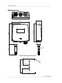
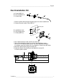
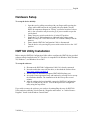
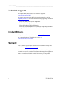
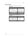
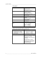
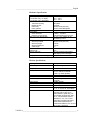
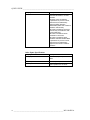
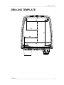
QUICK GUIDE
Vaisala HUMICAP® Humidity and
Temperature Transmitter
HMT140
English
M211484EN-A
PUBLISHED BY
Vaisala Oyj
P.O. Box 26
FI-00421 Helsinki
Finland
Phone (int.):
Fax:
+358 9 8949 1
+358 9 8949 2227
Visit our Internet pages at www.vaisala.com.
© Vaisala 2012
No part of this manual may be reproduced in any form or by any means, electronic or
mechanical (including photocopying), nor may its contents be communicated to a third party
without prior written permission of the copyright holder.
The contents are subject to change without prior notice.
Please observe that this manual does not create any legally binding obligations for Vaisala
towards the customer or end user. All legally binding commitments and agreements are
included exclusively in the applicable supply contract or Conditions of Sale.
__________________________________________________________________________
Table of Contents
ENGLISH ........................................................................................................ 5
Product Overview ..................................................................... 5
Dimensions ............................................................................... 6
Duct Installation Kit.................................................................. 7
Wiring ........................................................................................ 8
Hardware Setup ...................................................................... 11
HMT140 Utility Installation..................................................... 11
HMT140 Utility Configuration ................................................ 12
Battery Replacement.............................................................. 12
IR Sensor ................................................................................. 13
Technical Support .................................................................. 14
Product Returns ..................................................................... 14
Warranty .................................................................................. 14
Technical Data ........................................................................ 15
DRILLING TEMPLATE................................................................................. 19
VAISALA_________________________________________________________________ 3
QUICK GUIDE ______________________________________________________________
This page intentionally left blank.
4
_____________________________________________________________ M211484EN-A
____________________________________________________________________ English
ENGLISH
Product Overview
The Vaisala HUMICAP® Wireless Humidity and Temperature Transmitter
HMT140 measures relative humidity and temperature using the connected
probe and analog signals – RTD, Voltage, Current loops and Contacts. It
outputs data via wireless transmitter and is powered with three 3.6 volt DC
batteries and optional 9-30VDC connection and comes in 2 models, with or
without the optional LCD display.
The HMT140 transmitter's output quantities are configurable. Available
quantities are Relative Humidity (RH), Temperature (T), RTD, Contact, mV
and mA. The default output quantities are set at the factory during order time.
These factory preset quantity selections and other wireless parameters can be
changed afterward using the configuration port and included utility if necessary.
The HMT140 is available either with a fixed probe directly attached to the
transmitter housing or a remote probe with different (3/5/10m) cable lengths.
The HMT140 is also available with an optional LCD display without backlight.
It is typically installed mounted on the wall with up to four screws (not
included). Duct installation kits are available as accessories. There is a drilling
template inside the back cover of this guide to help you position the screws
correctly.
VAISALA_________________________________________________________________ 5
QUICK GUIDE ______________________________________________________________
Dimensions
116
37
145
124
120
72
Ø 12
Wall Assembly dimensions
78
M4
;4
pc
s
91
39
46
92
6
_____________________________________________________________ M211484EN-A
____________________________________________________________________ English
Duct Installation Kit
A
A = Probe (HMP110)
B = Duct installation kit
C = Probe Cable
B
C
1. Pass the probe cable through the plastic pipe of the duct installation kit.
2. Connect the probe cable to the HMP110.
Ø3,2x 4 pcs
Ø24
42
D = Installation screw
E = Pipe locking screw
F = Probe (HMP110)
F
E
D
3. Use a 24mm drill bit to make a hole in the duct wall.
4. Use a 3.2mm drill bit to make four holes for the installation screws
(ST4.2x16-C-Z DIN7981 screw, 4pcs). The holes should be arranged
in a square around the 24mm hole, at a distance of 42mm from each other.
5. Mount the probe holder using the screws (D).
6. Adjust the depth of the plastic pipe and tighten the screw (E)
to lock the probe in place.
29
Ø12
53
42
Ø22
Ø 15
6
20
59
205
266
42
42
VAISALA_________________________________________________________________ 7
QUICK GUIDE ______________________________________________________________
Wiring
Ir Sensor
Status
LED
+
P
S
8
y 31
re 6
tt 23
a
B N
V /
6 P
3. la
a
s
ai
V
Service
Switch
P
S
8
1
y 3
re 6
tt 3
a 2
B N
V /P
6 a
.3 l
a
s
ia
V
SERVICE
+
ON
LCD
Display
Power
Switch
OFF
CONFIG
+
Config
Header
Va
is 3.6V
ala
P/ Batt
N
e
23 ry
63
18
SP
Release Tab
Cable grommet
(Rubber plug)
Cable bushing:
cable gland,
cable grommet,
or conduit fitting
Field WireTerminals
HMT140 Components
8
_____________________________________________________________ M211484EN-A
____________________________________________________________________ English
1) RTD Wiring Diagram
Channel 1: RTD
Channel 2: RTD
VAISALA_________________________________________________________________ 9
QUICK GUIDE ______________________________________________________________
4) Voltage Wiring Diagram
Channel 2: DC Volatge
10
+
VinDC
V+ G
V+ G
V+ G
V+ G
Channel 1
Channel 2
Channel 1
Channel 2
Channel 1: DC Voltage
+
VinDC
____________________________________________________________ M211484EN-A
____________________________________________________________________ English
Hardware Setup
To set up the device initially:
1. Open the case by pulling out and up with your fingers while pressing the
release tab located between the two glands with your thumb. (See the
HMT140 components diagram in “Wiring” section for location of release
tab). A slot screwdriver may be used to pry if you are unable to open the
case by hand.
2. Ensure the power switch on the device is in the OFF position.
3. Install three 3.6V lithium batteries as indicated in the wiring section.
Note: Use only Part # 236318SP Vaisala 3.6V Lithium Thionyl Chloride
batteries.
4. Ensure that the HMT140 Configuration Cable is disconnected.
5. Turn the device on by moving the power switch on the device to the “ON”
position.
HMT140 Utility Installation
Before using the HMT140 Configuration Cable cable to configure the HMT140, the provided
software must be installed on the PC. The driver is compatible with Windows 2000, Windows
XP, Windows 7, and Windows Server 2003.
To set up the software:
1. Disconnect the HMT140 Configuration Cable if it is already connected.
2. Insert the media that came with the cable, or download the software from
http://www.vaisala.com/hmt140
3. Run the HMT140 installation program (HMT140UtilitySetup.exe).
4. Accept the license agreement terms and continue by pressing Next to accept
the installation defaults. The installation of the driver may take several
minutes.
5. After the software has been installed, connect the HMT140 Configuration
Cable to a USB port on your PC. You can then proceed to configure the
utility using the steps below.
If you wish to remove the software, you can do so by uninstalling the entry for HMT140
Utility under the publisher Vaisala from the “Programs and Features” or “Add or Remove
Programs” feature in the Windows Control Panel.
VAISALA_________________________________________________________________ 11
QUICK GUIDE ______________________________________________________________
HMT140 Utility Software Setup
Use the following procedure to quickly set up the HMT140:
1.
2.
3.
4.
5.
6.
7.
8.
Turn on the HMT140 and wait 5 seconds.
Plug the USB connector on the HMT140 Configuration Cable to the
computer if it is not already connected.
Open the HMT140 Utility from the start menu.
Connect the end of the Configuration cable labelled “USB Wi-Fi
Programmer” to the HMT140 “CONFIG” pin header.
Click the Retrieve button to identify the HMT140.
If the IP address is static, uncheck the “IP Address Dynamically Assigned”
checkbox and enter the network parameters in “Network Settings”.
Otherwise leave this checkbox checked.
Enter the parameters for the “WLAN” (wireless LAN router settings).
Enter the Destination IP address/name and port number of the host.
(viewLinc server settings).
Note: If you do not know the information to enter for steps 6-9, please request
these parameters from your network administrator.
9. Click the Sensor tab and select a Transmit Period Time and number of tries
for the HMT140 if you do not wish to keep the default settings.
10. Click the Update button. The utility will configure the HMT140.
11. Click the Status tab and wait. Check that the settings appear as configured.
Click the “Get” button if they do not appear automatically.
12. Disconnect the HMT140 Configuration cable from the HMT140.
13. Wait 8 seconds.
14. Press the “SERVICE” button on the HMT140.
15. Optional: Enter a name for the saved settings in the Saved Settings field and
click the disk icon to save.
16. Refer to the viewLinc Administrator Guide to complete the process of
adding HMT140’s to viewLinc.
Battery Replacement
Use the following procedure to replace the batteries in the HMT140:
1. Open the case by pulling out and up with your fingers while pressing the
release tab located between the two glands with your thumb. (See the
HMT140 components diagram in “Wiring” section for location of release
tab).
2. Turn the power switch off.
3. Remove the batteries by pulling them up firmly. If the battery does not
come out easily, one of the battery tabs can be pulled out gently while
pulling up.
4. After replacing the batteries, press and hold the service button and turn the
power switch on. The LED light will flash and the device will beep 8 times.
5. Release the service button.
12
____________________________________________________________ M211484EN-A
____________________________________________________________________ English
To reset the battery meter:
1. Turn off the HMT140. Make sure the configuration Cable is disconnected
from the sensor.
2. Press and hold the service button.
3. Turn the HMT140 on while the service button is engaged.
4. Wait four seconds.
5. Release the service button. The battery meter has been reset.
IR Sensor
Use the following procedure to trigger a data packet transmission using the
IR Sensor:
1. Turn on the HMT140 and wait for the display to turn on then off.
2. Place your hand near the display. The display will turn on again and the
beeper will beep.
3. To trigger a data packet transmission, ensure the Configuration Cable is
disconnected from the HMT140 (Sensor mode).
4. Place your hand over the display again and leave it for 5 seconds. The
Logger will beep twice to confirm transmission. It will attempt to connect
and transmit data to the host.
VAISALA_________________________________________________________________ 13
QUICK GUIDE ______________________________________________________________
Technical Support
The complete HMT140 User's Guide is available in English at
www.vaisala.com/hmt140.
For technical questions, contact the Vaisala technical support by e-mail at
[email protected]. Provide at least the following supporting information:
-
Name and model of the product in question.
Serial number of the product.
Name and location of the installation site.
Name and contact information of a technically competent person who
can provide further information on the problem.
Product Returns
If the product must be returned for service, see www.vaisala.com/returns.
For contact information of Vaisala Service Centers, see
www.vaisala.com/servicecenters.
Warranty
Visit our Internet pages for more information and our standard warranty terms
and conditions: www.vaisala.com/warranty.
Please observe that any such warranty may not be valid in case of damage due
to normal wear and tear, exceptional operating conditions, negligent handling or
installation, or unauthorized modifications. Please see the applicable supply
contract or Conditions of Sale for details of the warranty for each product.
14
____________________________________________________________ M211484EN-A
____________________________________________________________________ English
Technical Data
Humicap Relative Humidity Measurement Specifications
(With HMP110)
Property
Measurement range
Accuracy (including non-linearity,
hysteresis, and repeatability):
at 0 ... +40 °C (+32 ... +104 °F)
at -40 ... 0 °C and +40 ... +80 °C
(-40 ... +32 °F and +104...+176 °F)
Factory calibration uncertainty at
20 °C (+68 °F)
Humidity sensor
Stability
Description / Value
0 ... 100 % RH
±1.7 %RH (0 ... 90 % RH)
±2.5 %RH (90 ... 100 % RH)
±3.0 %RH (0 ... 90 % RH)
±4.0 %RH (90 ... 100 % RH)
±1.5 %RH
HUMICAP® 180R
±2 %RH over 2 years
Humicap Temperature Measurement Specifications
(With HMP110)
Property
Measurement range
Accuracy over temperature range:
at +15 ... +25 °C (+59 ... +77 °F)
at 0 K+15 °C and +25 K+40 °C
(+32 ... +59 °F and +77 ...+104 °F)
at -40 ... 0 °C and +40 ... +80 °C
(-40 ... +32 °F and +104...+176 °F)
Temperature sensor
Description / Value
-40 ... +80 °C (-40 ... +176 °F)
±0.2 °C (±0.36 °F)
±0.25 °C (±0.45 °F)
±0.4 °C (±0.72 °F)
Pt1000 RTD 1/3 Class B IEC 751
VAISALA_________________________________________________________________ 15
QUICK GUIDE ______________________________________________________________
Analog Inputs
Property
2 Channel Current input signals
Description / Value
0-22 mA
Resolution: 0.67 µA
Accuracy: ±0.15 % F.S. at +25 °C
Input Impedance: 62 Ohms
2 Channel Voltage input signals
0-5 V, 0-10 V
Resolution 0.0034% F.S.
±0.15 % F.S. at +25 °C
Input Impedance: 37K Ohms
2 Boolean Contacts
Open /Close with magnetic reed relay
cable connections
Isolation
One common per logger
Overload Protection
40 mA max. (reverse polarity
protected)
±24 VDC max. (reverse
polarity protected)
2 Resistive Temperature input signal Pt 100 RTD / 4 wire
Class A IEC 751
RTD Measurement range
-196 °C to +90 °C
RTD Accuracy over temperature
-196 to -90 +/- 2.5 Deg C.
range
-90 to -30 +/- 0.75 Deg C
-30 to 0 +/- 0.5 Deg C
0 to 50 +/- 0.25 Deg C
50 to 90 +/- 0.75 Deg C
2 Contacts input signals
Dry contact
Humicap Operating Environment Specifications
Property
Operating temperature range
Transmitter body, no display
Transmitter body, with display
HMP110 probe
Storage temperature range
Electromagnetic compatibility
Description / Value
-40 ... +60 °C (-40 ... +140 °F)
-20 ... +60 °C (-4 ... +140 °F)
-40 ... +80 °C (-40 ... +176 °F)
-50 ... +70 °C (-58 ... +158 °F)
EN 61326-1:2006 Electrical
equipment for measurement, control
and laboratory use - EMC
requirements - Basic immunity test
requirements
EN 55022:2006 + Am 1:2007
Information technology equipment Radio disturbance characteristics Limits and methods of
measurement. Class B.
16
____________________________________________________________ M211484EN-A
____________________________________________________________________ English
Mechanics Specifications
Property
Operating Temperature Range
Transmitter body, no display
Transmitter body, with display
Material
Transmitter housing
Display window
Probe body
Probe grid filter
Housing classification
Connections
Screw terminals
HMP110 Probe interface
HMP110 Probe cable lengths
RTD Temperature Sensor
Sensor tip material
Sensor tip length
Sensor tip diameter
Cable length
Hermetic Door Switch Sensor
Cable length
Display (optional)
Description / Value
-40°C...+60°C
-20°C...+60°C
PBT plastic
PC plastic
Stainless steel (AISI 316)
Chrome coated ABS plastic
IP65 (NEMA 4)
26 AWG ... 20 AWG
4-pin M8 female panel connector
3 m, 5 m, 10 m, cables can be
cascaded up to 50 m
Stainless steel (AISI 316)
50.8 mm
4.76 mm
5m
7.6 m
128 x 64 resolution full graphics
B&W display without backlight
Weight (Wall model, including probe) 300 g
Wireless Specifications
Property
Networking Standards
Description / Value
IEEE 802.11 b/g
Frequency Band
Modulation
2402 ~ 2480MHz
802.11b compatibility: DSSS(CCK-11,
CCK-5.5, DQPSK-2, DBPSK1) 802.11g: OFDM (default)
5MHz
1 - 14
WEP (128-bit), WPA, WPA2
(Personal)
+18dBm (63mW)
-85dBm typical
Onboard Wipe
802.11 b: 1,2, 5.5,11 Mbps : 802.11
g: 6, 9, 12, 18, 24, 36, 48, 54 Mbps
FCC: U3O-G2M5477 (FCC Part 15,
FCC CRF Title 47 Part 15) IC:
8169A-G2M5477 (RSS-210), CE:
EU ID # 0681 (ETSI EN 301 489-1,
489-17, 328, EN 55022 Class B,
EN61000 4-2, 4-3, 4-6, 4-8, EN
60950) Wi-Fi Certified: WFA7649
United States requirements for
unintentional radiators, FCC 47 CFR
Part 15-2011 Subpart B.
Channel intervals
Channels
Wi-Fi Security
Output Power
Receiver Sensitivity
Antenna
Data Rates
Certifications
VAISALA_________________________________________________________________ 17
QUICK GUIDE ______________________________________________________________
Property
Description / Value
Canadian requirements for
unintentional radiators, IC ICES003:2004
European Union CE Marking
requirements for process control,
measurement, and laboratory
equipment (EMC Directive
2004/108/EC):EN 61326-1:2006 for
emissions and immunity
EN 61326-2-3:2006 for emissions
and immunity of transducers with
signal conditioning
EN 61000-3-2:2006+A1:2009
+A2:2009 for harmonics
EN 61000-3-3:2008 for flicker
Australian and New Zealand EMC
requirements for process control,
measurement, and laboratory
equipment, EN 61326-1:2006 for
emissions.
Other Inputs Specifications
18
Property
Voltage inputs
Description / Value
50Volts max, input impedances 37K
Ohms
Current inputs
RTD inputs
40 mA., input impedances 62 Ohms
not a voltage or current input device,
input impedances 5.1K Ohms
____________________________________________________________ M211484EN-A
_____________________________________________________________ Drilling template
DRILLING TEMPLATE
78
91
39
46
M4
92
VAISALA_________________________________________________________________ 19
www.vaisala.com
M211484EN-A