1
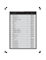
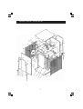
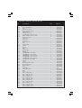
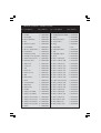
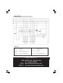
FAN HEATER
Models: DEVIL 4040 • 4060 • 4100 • 4120
OPERATING & MAINTENANCE
INSTRUCTIONS
0905
DECLARATION of CONFORMITY
We declare that this product complies with the following standards/directives:
•
•
73/23/EEC
98/336/EEC
Serial/Batch No: See Data Plate
signed
Engineering Manager
SPECIFICATIONS
Model Number
Devil 4040
Devil 4060
Devil 4100
Devil 4120
Input
230V 50hz 1ph
400V 50hz 3ph
400V 50hz 3ph
400V 50hz 3ph
Output Rating
3kW
5kW
9kW
15kW
Supply Fuse Rating
13A
15A
15A
25A
Dimensions (mm)
260x260x410
3
360x280x380
3
440x330x490
3
480x370x520
1700m3/h
Air Output
510m /h
510m /h
800m /h
Noise Level
50dBLWA
50dBLWA
52dBLWA
54dBLWA
Gross Weight
7.5kg
8.0kg
13.5kg
15.5kg
Part No.
6925160
6925165
6925170
6525175
PARTS & SERVICE
PARTS & SERVICE TEL: 020 8988 7400
or e-mail as follows:
PARTS: [email protected]
SERVICE:
[email protected]
Waste electrical products should not be disposed of with household waste. Please
dispose of at your local recycling facility.
© Copyright Clarke International. All rights reserved Feb. 2002
2
Thank you for purchasing this Clarke Fan Heater.
Before attempting to operate the unit please read this instruction leaflet and carefully
follow all directions given. By doing so you will ensure safe operation of the unit and you
can also look forward to it providing you with long and trouble free service.
GUARANTEE
This CLARKE product is guaranteed against faults in manufacture for 12 months
from purchase date. Please keep your receipt as proof of purchase.
This guarantee is invalid if the product has been found to have been abused in
any way, or not used for the purpose for which it was intended, or to have been
tampered with in any way. The reason for return must be clearly stated.
This guarantee does not affect your statutory rights.
SAFETY PRECAUTIONS
•
This heater is for INDOOR USE ONLY.
•
NEVER use electrical equipment in the presence of combustible gases.
•
ALWAYS disconnect from the mains supply before moving or performing any
maintenance tasks.
•
ALWAYS use in an upright position ONLY.
•
Inspect the mains cable regularly for signs of damage. DO NOT use if it is
damaged, and ALWAYS keep it away from the source of heat.
•
NEVER remove the guards from this machine.
•
NEVER locate the heater near combustible materials such as curtains, furniture
etc. Allow at least 1 metre distance.
•
DO NOT use this heater in a bathroom , shower room, in the vicinity of a
swimming pool, or any wet environment.
•
DO NOT locate the heater close to an adjacent wall or ceiling...allow a
distance of at least 1 metre from a wall or ceiling.
•
NEVER cover the heater, or block any of the vents.
•
DO NOT use if the heater elements are damaged.
•
NEVER touch the heater for at least 15 minutes after it is switched off.
•
DO NOT leave the heater unattended.
•
If children are present.....ALWAYS use with a fireguard.
•
Do NOT use in a paint spray booth or any explosive environment.
•
Take care to ensure that the fan grille cannot be blocked by curtains or the like.
3
ELECTRICAL CONNECTIONS
Devil 4040
This model is provided with a 13 amp BS 1363 plug, fitted with a 13amp fuse and MUST be
connected to a standard, 230 Volt (50Hz) electrical supply, preferably through an approved plug , or a suitably fused isolator switch.
WARNING! THIS APPLIANCE MUST BE EARTHED
IMPORTANT: The wires in the mains lead are coloured in accordance with the following
code:
Green & Yellow ................................ Earth
Blue .................................................... Neutral
Brown ................................................ Live
As the colours of the flexible lead of this appliance may not correspond with the coloured
markings identifying terminals in your plug, or your mains supply, proceed as follows:
•
Connect GREEN & YELLOW coloured cord to plug terminal marked with a letter “E” or
Earth symbol “ ” or coloured GREEN or GREEN & YELLOW.
•
Connect BROWN cord to terminal marked with a letter “L” or coloured RED.
•
Connect BLUE cord to terminal marked with a letter “N” or coloured BLACK.
Fuse Rating
The fuse in the plug must be replaced with one of the same rating (13 amps) and this
replacement must be ASTA approved to BS1362.
This appliance is fitted with a plug which is moulded on to the electric cable (i.e. nonrewireable) please note:
1. The plug must be thrown away if it is cut from the electric cable. There is a danger of
electric shock if it is subsequently inserted into a socket outlet.
2. Never use the plug without the fuse cover fitted.
3. Should you wish to replace a detachable fuse carrier, ensure that the correct
replacement is used (as indicated by marking or colour code).
4. Replacement fuse covers can be obtained from most DIY or electrical stores.
Devils 4060, 4100 & 4120
These machines MUST be connected to a 400 Volt, 3 PHASE 50Hz supply through a suitably
fused isolator switch. It cannot be operated from a single phase supply.
A trailing socket is NOT provided, but is available from your CLARKE dealer,
Part No:
It is important to note, that the PLUG is wired as shown in the
illustration opposite, as viewed from the outside of the unit - the
socket should be wired correspondingly.
• The GREEN or GREEN & YELLOW coloured wire, is connected to
the terminal marked with the letter “E” or Earth symbol “ ”
• The BLACK or Blue wire is connected to the ‘N’ or Neutral terminal.
• The Remaining wires are connected to the terminals marked L1, L2 and L3.
4
WARNING!
IF YOU ARE IN ANY DOUBT ABOUT ELECTRICAL CONNECTIONS, CONSULT A
QUALIFIED ELECTRICIAN.
DO NOT ATTEMPT ELECTRICAL CONNECTIONS or REPAIRS YOURSELF.
OPERATION
With the heater suitably sited (ensure you comply with all safety precautions),
switch the heater ON to either fan only, half or full output (see illustration below).
A temperature control switch (A) is also provided for fine control of heat output.
Should the unit overheat, a thermal cutout will operate, shutting down the unit.
Allow a period of time for the unit to cool (approx. 10 minutes) before pressing the
reset using a suitable pointed tool, and restarting.
When switching the unit OFF, it is strongly recommended that it is run in the FAN
ONLY mode for approx. 10 minutes, in order to cool the elements, before switching
OFF completely and finally disconnecting from the mains supply.
The thermal cutout may also operate if the heater is shut down without allowing
to cool sufficiently. If, subsequently, the machine fails to start, press the reset using
a suitable tool and try again.
A.
B.
C.
D.
E.
F.
Temperature control sw.
OF/OFF Switch
OFF
Fan Only
Fan w/ Single Element
Fan w/ Both Elements
MAINTENANCE
Before performing any maintenance tasks, if the heater has been used, ALWAYS
allow it to cool down for at least 10 minutes, by switching to FAN ONLY, then
disconnect from the mains supply.
Periodically.
•
Disconnect from the mains supply, and use compressed air at low pressure to
clean out the unit. ALWAYS wear a dust mask to perform this operation.
If there is any serious build up of dirt, it is possible to remove the bottom cover, by
unscrewing the 6 self tapping screws securing it, to gain access to the fan and
heating elements. Clean these thoroughly taking great care not to distort the fan.
Ensure the bottom cover is firmly secured when completed.
•
Inspect the mains cable for damage. Heat damage will cause the cable to
stiffen and crack. If this is found, have the cable replaced. Check cable routing
and ensure it is well away from the heat source.
5
SPARE PARTS - DEVIL 4040
6
SPARE PARTS - DEVIL 4040
No.
Description
1.1
1.2
1.3
1.4
2
3
4
5
6
7
8
9
10
11
12
13
14
15
16
17
18
19
20
21
22
23
24
25
26
27
28
29
30
31
32
33
34.1
34.2
35
Motor Sw/230v
Fan
Washer 4,3 12mm
Screw M4x16
Top Cover
Round Cover
Side Cover
Down Cover
Heat Shield
Shelf
Back Cover
Name Plate
Heating Element 1400W
Switch
Bim Etal Thermostat
Overheat Sensor
Temp Limiter
Power Cord
Screw Terminal Block
Data Plate
Label Ground Wire
Handle
Strain Relief Bushing
Leg Rubber
Belt
Knob
Electrical Wire Set
Tap Screw 5t3,5x9,5
Nut M4
Washer A4
Washer A4, 3
Tap Screw M4x8
Tap Screw M4x16
Screw M6x14
Nut M6
Washer A6
Reset Lever
Base For Reset Lever
Front Cover
Qty
1
1
1
1
1
1
2
1
1
1
1
1
2
1
1
1
1
1
1
1
1
1
1
4
2
2
1
4
3
6
7
3
1
2
2
2
1
1
1
7
Part No.
DE4510301
DE4510317
DE4510812
DE4510807
See Your Dealer
See Your Dealer
See Your Dealer
See Your Dealer
See Your Dealer
See Your Dealer
See Your Dealer
See Your Dealer
DE4510362
DE4510401
DE4510403
DE4510404
DE4510405
DE4510408
DE4510421
N/A
N/A
DE4510601
DE4510605
DE4510607
DE4510608
DE4510610
DE4510740
DE4510801
DE4510808
DE4510810
DE4510811
DE4510814
DE4510828
DE4510829
DE4510830
DE4510831
DE4510612
DE4510611
See Your Dealer
SPARE PARTS - DEVIL 4060
8
SPARE PARTS - DEVIL 4060
No.
Description
Qty
1.1
1.2
1.3
1.4
2.1
2.2
3.1
3.2
3.3
3.4
4
5
6
7
8
9
10
11
12
13
14
15
16
17
18
19
20
21
22
23
24
25
26
27
28
29
30
31
32
32
32
32
32
32
32
32
32
32
32
32
Screw M4x16 ............................................................. 1 ................. DE4510807
Motor 12w/230v ........................................................ 1 ................. DE4510306
Fan .............................................................................. 1 ................. DE4510317
Washer 4,3 12mm ..................................................... 1 ................. DE4510812
Base For Reset Button .............................................. 1 ................. DE4510611
Reset Button .............................................................. 1 ................. DE4510612
Handle Assembly ...................................................... 2 ................. DE4510128
Self Tapping Screw ST3,9x25 .................................... 8 ................. DE4510817
Plastic Distance Piece15mm .................................. 8 ................. DE4510603
End Cap 12mm ........................................................ 4 ................. DE4510604
Fan Cowl ................................................................... 1 ................. DE4510112
Side Cover ................................................................. 2 ................. DE4510117
Bottom Cover ........................................................... 1 ................. DE4510121
Facia .......................................................................... 1 ................. DE4510136
Grill .............................................................................. 2 ................. DE4510138
Heat Shield ................................................................ 1 ................. DE4510139
Washer ....................................................................... 3 ................. DE4510140
Top Cover .................................................................. 1 ................. DE4510143
Tray ............................................................................. 1 ................. DE4510181
Washer A4 ................................................................. 2 ................. DE4510810
Washer A4,3 .............................................................. 1 ................. DE4510811
Nut M4 ....................................................................... 3 ................. DE4510808
Self Tapping Screw M4x8 ......................................... 3 ................. DE4510814
Self Tapping ScrewM4x16 ........................................ 1 ................. DE4510828
Self Tapping Screw ST3,5x9,5 ................................... 4 ................. DE4510801
Self Tapping Screw ST3,9x13 .................................... 4 ................. DE4510818
Self Tapping Screw ST3,9x9,5 .................................. 40 ................ DE4510802
Heating Element 1666w ........................................... 3 ................. DE4510359
Switch ......................................................................... 1 ................. DE4510401
Relay .......................................................................... 1 ................. DE4510402
Bi-metal Thermostat ................................................. 1 ................. DE4510403
Overheat Sensor ....................................................... 1 ................. DE4510404
Temperature Limiter ................................................. 1 ................. DE4510405
Plug ............................................................................ 1 ................. DE4510406
Data Plate ................................................................. 1 ................. N/A
Label Earth Wire ........................................................ 1 ................. DE4510536
Belt .............................................................................. 3 ................. DE4510608
Knob ........................................................................... 2 ................. DE4510610
Wire 1.5 Blue 0.08 ...................................................... 2 ................. DE4510900
Wire 1.5 Brown 0.12 .................................................. 1 ................. DE4510910
Wire 1.5 Brown 0.13 .................................................. 1 ................. DE4510911
Wire 1.5 Blue 0.16 ...................................................... 1 ................. DE4510913
Wire 1.5 Brown 0.20 .................................................. 1 ................. DE4510916
Wire 1.5 Brown 0.20 .................................................. 2 ................. DE4510917
Wire 1.5 Blue 0.08 ...................................................... 1 ................. DE4510919
Wire 1.5 Brown 0.24 .................................................. 2 ................. DE4510925
Wire 1.5 Blue 0.30 ...................................................... 1 ................. DE4510926
Wire 1.5 Brown 0.38 .................................................. 1 ................. DE4510934
Wire 1.5 Brown 2x0.15 ............................................... 1 ................. DE4510937
Wire 2.5 Yellow 0.10 .................................................. 1 ................. DE4510938
9
Part No.
SPARE PARTS - DEVIL 4100
10
SPARE PARTS - DEVIL 4100
No.
1.1
1.2
1.3
1.4
2.1
2.2
3.1
3.2
3.3
3.4
4
5
6
7
8
9
10
11
12
13
14
15
16
17
18
19
20
21
22
23
24
25
26
27
28
29
30
31
32
32
32
32
32
32
32
32
32
32
32
32
Description
Qty
Screw M4x16 ....................................................................
Motor 16W/230V ..............................................................
Fan .....................................................................................
Washer 4,3 12mm ............................................................
Base For Reset Button .....................................................
Reset Button .....................................................................
Handle Assembly .............................................................
Self Tapping Screw ST3,9x25 ...........................................
Plastic Distance Piece 15mm ........................................
End Cap 12mm ...............................................................
Top Cover .........................................................................
Fan Cowl ..........................................................................
Side Cover ........................................................................
Bottom Cover ..................................................................
Grill .....................................................................................
Heat Shield .......................................................................
Facia .................................................................................
Washer ..............................................................................
Tray ....................................................................................
Washer A4 ........................................................................
Washer A4,3 .....................................................................
Nut M4 ..............................................................................
Self Tapping Screw M4x8 ................................................
Self Tapping Screw M4x16 ..............................................
Self Tapping Screw ST3,5x9,5 ..........................................
Self Tapping Screw ST3,9x13 ...........................................
Self Tapping Screw ST3,9x9,5 ..........................................
Heating Element 3000W .................................................
Switch ................................................................................
Relay .................................................................................
Bi-metal Thermostat ........................................................
Overheat Sensor ..............................................................
Temp Limiter .....................................................................
Plug ...................................................................................
Data Plate ........................................................................
Label Earth Wire ...............................................................
Belt .....................................................................................
Knob ..................................................................................
Wire 1.5 Blue 0.08 .............................................................
Wire 1.5 Brown 0.12 .........................................................
Wire 1.5 Brown 0.13 .........................................................
Wire 1.5 Blue 0.16 .............................................................
Wire 1.5 Brown 0.20 .........................................................
Wire 1.5 Brown 0.20 .........................................................
Wire 1.5 Blue 0.08 .............................................................
Wire 1.5 Brown 0.24 .........................................................
Wire 1.5 Blue 0.30 .............................................................
Wire 1.5 Brown 0.38 .........................................................
Wire 1.5 Brown 2x0.15 ......................................................
Wire 2.5 Yellow 0.10 .........................................................
11
1 ..............
1 ..............
1 ..............
1 ..............
1 ..............
1 ..............
2 ..............
8 ..............
8 ..............
4 ..............
1 ..............
1 ..............
2 ..............
1 ..............
2 ..............
1 ..............
1 ..............
3 ..............
1 ..............
2 ..............
1 ..............
3 ..............
3 ..............
1 ..............
4 ..............
4 ..............
36 ............
3 ..............
1 ..............
1 ..............
1 ..............
1 ..............
1 ..............
1 ..............
1 ..............
1 ..............
3 ..............
2 ..............
2 ..............
1 ..............
1 ..............
1 ..............
1 ..............
2 ..............
1 ..............
2 ..............
1 ..............
1 ..............
1 ..............
1 ..............
Part No.
DE4510807
DE4510307
DE4510318
DE4510812
DE4510611
DE4510612
DE4510129
DE4510817
DE4510603
DE4510604
DE4510104
DE4510114
DE4510119
DE4510123
DE4510125
DE4510127
DE4510137
DE4510140
DE4510183
DE4510810
DE4510811
DE4510808
DE4510814
DE4510828
DE4510801
DE4510818
DE4510802
DE4510360
DE4510401
DE4510402
DE4510403
DE4510404
DE4510405
DE4510406
N/A
DE4510536
DE4510608
DE4510610
DE4510900
DE4510910
DE4510911
DE4510913
DE4510916
DE4510917
DE4510919
DE4510925
DE4510926
DE4510934
DE4510937
DE4510938
SPARE PARTS - DEVIL 4120
12
SPARE PARTS - DEVIL 4120
No. Description
Qty Part No.
No. Description
Qty Part No.
1.1 Screw M5x14
1
DE4510825
23 Capillary Thermostat
1
DE4510416
1.2 Nut M4
4
DE4510808
24 Heating Element 2500W 6
DE4510355
1.3 Fan Guard
1
DE4510166
25 Relay
2
DE4510402
1.4 Motor 25W/230V
1
DE4510304
26 Overheat Sensor
1
DE4510404
1.5 Fan
1
DE4510314
27 Temp Limiter
1
DE4510405
1.6 Washer 5,3 20mm
1
DE4510824
28 Plug
1
DE4510411
1.7 Screw M4x60
4
DE4510833
29 Data Plate
1
N/A
2.1 Base For Reset Button
1
DE4510611
30 Label Earth Wire
1
DE4510536
2.2 Reset Button
1
DE4510612
31 Belt
3
DE4510608
3.1 Handle Assembly
2
DE4510170
32 Capillary Support
2
DE4510609
3.2 Self Tap Screw ST3,9x25 8
DE4510817
33 Knob
2
DE4510610
3.3 Distance Piece 15mm
8
DE4510603
34 Wire 1.5 Blue 0.08
4
DE4510900
3.4 End Cap 12mm
4
DE4510604
34 Wire 1.5 Brown 0.08
1
DE4510901
4
Side Cover
2
DE4510157
34 Wire 1.5 Blue 0.10
1
DE4510902
5
Top Cover
1
DE4510145
34 Wire 1.5 Brown 0.10
1
DE4510903
6
Tray
1
DE4510149
34 Wire 1.5 Brown 0.12
1
DE4510906
7
Fan Cowl
1
DE4510153
34 Wire 1.5 Brown 0.16
1
DE4510912
8
Bottom Cover
1
DE4510161
34 Wire 1.5 Brown 0.16
2
DE4510914
9
Grill
2
DE4510164
34 Wire 1.5 Brown 0.18
4
DE4510915
1
DE4510168
34 Wire 1.5 Brown 0.20
1
DE4510916
10 Heat Shield
11 Facia
1
DE4510173
34
Wire 1.5 Brown 0.20
1
DE4510917
12 Screw Terminal
1
DE4510414
34 Wire 1.5 Brown 0.22
1
DE4510920
13 Washer A4
2
DE4510810
34 Wire 1.5 Brown 0.23
1
DE4510923
14 Washer A4,3
1
DE4510811
34 Wire 1.5 Brown 0.23
1
DE4510924
15 Nut M4
3
DE4510808
34 Wire 1.5 Blue 0.25
1
DE4510929
16 S/Tap Screw M4x8
2
DE4510814
34 Wire 1.5 Blue 0.28
1
DE4510930
17 S/Tap Screw M4x16
1
DE4510828
34 Wire 1.5 Brown 0.31
1
DE4510931
18 S/Tap Screw ST3,5x9,5
2
DE4510801
34 Wire 1.5 Blue 0.31
1
DE4510932
19 S/Tap Screw ST3,9x13
12 DE4510818
34 Wire 4 Brown 0.24
3
DE4510939
20 S/Tap Screw ST4,8x13
16 DE4510821
34 Wire 4 Blue 0.24
1
DE4510943
34 Wire 4 Yellow 0.30
1
DE4510944
21 S/Tap Screw ST3,9x9,5 27 DE4510802
22 Switch
1
DE4510401
13
WIRING DIAGRAMS
Devil 4040
Devil 4060 4100
14
Devil 4120
LEGEND
W..............Switch
T...............Thermostat
M..............Motor
PK.............Relay
WR...........Temperature Limiter
L...............Coil
WZ............Overheating Sensor
R1 - R6.....Heating Elements
PARTS & SERVICE
PARTS & SERVICE TEL: 020 8988 7400
or e-mail as follows:
PARTS: [email protected]
SERVICE:
[email protected]
15