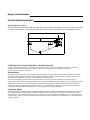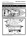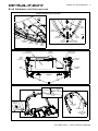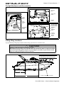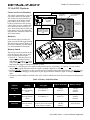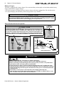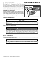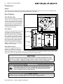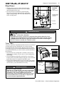
1
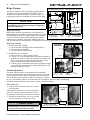
Engine Serial Number:
Hull Identification Number:
Hull Identification Number
The Hull Identification Number (HIN) is located on the starboard side of the transom. Be sure to record the HIN (and
the engine serial numbers) in the space provided above. Please refer to the HIN for any correspondence or orders.
HIN LOCATION
© 1999 Bayliner Technical Publications. All rights reserved.
No part of this publication may be reproduced, stored in any retrieval system, or transmitted in any form by any means,
electronic, mechanical, photocopying, recording or otherwise, without prior written permission of Bayliner.
Printed in the United States of America.
General Notes
The material in this document is for information only and is subject to change without notice. While reasonable efforts have
been made in the preparation of this document to assure its accuracy, Bayliner assumes no liability resulting from errors or
omissions in this document, or from the use of information contained herein.
Due to our commitment to product improvement, Bayliner reserves the right to make changes in the product design,
specifications, and equipment at any time without notice or obligation. Illustrations and/or photos may show optional equipment.
All Bayliner products meet or exceed USCG (Unites States Coast Guard) and/or NMMA (National Marine Manufacturer’s
Association) construction standards. Manufactured with 1,1,1 Trichloroethane, a substance which harms public health and
environment during the manufacturing process by destroying ozone in the upper atmosphere.
Proprietary Rights
This document discloses subject matter in which Bayliner has proprietary rights. The information and design disclosed herein
were originated by and are the property of Bayliner. Neither receipt nor possession thereof confers or transfers any right to
reproduce, copy, alter or disclose the document or any part thereof, any information contained therein, or to construct boats or
any item from it, except by written permission from or written agreement with Bayliner. This document is to be returned upon
request to Bayliner.
Congratulations and welcome aboard your new Bayliner Ciera!
Thank you for choosing our product. Bayliner is committed to the goal of building the
highest quality products in the marine industry and to providing the finest after-thesale support in the world.
To keep our respected status as the number one boat builder in the world, Bayliner has
instituted an ongoing Total Customer Satisfaction Program.
The guiding principles of this program are:
• Design, build and support the finest marine products in the world, in every market
we serve.
• Be personally and individually responsible for the customer’s total satisfaction.
• Remember that every customer has a choice, and we want them to choose Bayliner!
Welcome to the Bayliner family. We are looking forward to serving your boating
needs, now and in the future!
CONTENTS
CHAPTER 1: WELCOME ABOARD!
1
1
1
2
2
2
3
Dealer Service
Boating Experience
Engine/Accessories Guidelines
Qualified Maintenance
Special Care For Moored Boats
Safety Standards
Hazard Boxes & Symbols
CHAPTER 2: FEATURES/SYSTEMS
4
4
4
5
7
7
8
8
9
Dimensions and Tank Capacities
Layout View
Hull Exterior Hardware & Drains
Deck Hardware and Accessories
Cockpit Hardware and Accessories
Lifting Sling Locations
Windshield Wiper
Electrical System
12 Volt DC System
9
9
9
10
12
Fuses and Circuit Breakers
Batteries
Battery Switch
Battery Charger
Navigation & Communication Equipment
12 VHF Radio (LX models only)
12 Compass (LX models only)
12 Depth Finder (LX models only)
12
13
13
14
Audio Equipment
Lighting
Bilge Blower
Trim Tabs
Bilge Pumps
16 Autofloat Switches
17
Freshwater System (LX models only)
17 Water Heater
18 Transom Shower
18
Sink & Shower Drain Systems
18 Sump Box Cleaning
18 Sump System Winterization
19
Raw Water System
19 Seacocks
19 Raw Water Strainers
20
21
22
Marine Head with Holding Tank
Air Conditioning System (Option Available
on LX Models Only)
Canvas Top Installation
CHAPTER 3: ELECTRICAL ROUTINGS
23
24
25
Hull Wire Harness Routings
Deck Wire Harness Routings
Battery Cable Routings
CHAPTER 4: WIRING SCHEMATICS
26
27
28
29
Single Dockside
Dual Dockside
Gas Engine Electrical System
Diesel Engine Electrical System
13 Navigation and Interior Lights
LIMITED WARRANTY
Appliances
Propulsion
30
30
30
14 Engine
14
15
15
16
Fuel System
14 Fuel Fill and Vent:
14 Fuel Filters:
14 Anti-siphon Valve:
What Is Not Covered
Other Limitations
Your Obligation
Chapter 1: Welcome Aboard!
1
Chapter 1: Welcome Aboard!
This owner’s manual supplement provides specific information about your boat that is not covered in the owner’s
manual. Please study the owner’s manual and this supplement carefully, paying particular attention to the Limited
Warranty. Keep the owner’s manual and this supplement on your boat in a secure, yet readily available place.
De a le r S er v i ce
Make sure you receive a full explanation of all systems from the selling dealer before taking delivery of your boat.
Your selling dealer is your key to service. If you experience any problems with your new boat, immediately contact
the selling dealer. If for any reason your selling dealer is unable to help, you can call us direct on our customer service hotline: 360-435-8957 or send us a FAX: 360-403-4235.
B o a t in g E xp e r i en c e
If this is your first boat or if you are changing to a type of boat you are not familiar with, for your own comfort and
safety, please ensure that you obtain handling and operating experience before assuming command of the boat.
We strongly recommend that you take one of the boating safety classes offered by the U.S. Power Squadrons or the
U.S. Coast Guard Auxiliary. For more course information, including dates and locations of upcoming classes, contact
the organizations directly:
• U.S. Power Squadrons: 1-888-FOR-USPS (1-888-367-8777) or on the Internet at: http://www.usps.org
• U.S. Coast Guard Auxiliary: 1-800-368-5647 or on the Internet at: http://www.cgaux.org
Outside the United States, your selling dealer, national sailing federation or local boat club can advise you of local
sea schools or competent instructors.
!
WARNING!
CONTROL HAZARD! A qualified operator must be in control of the boat at all times. DO NOT
operate your boat while under the influence of alcohol or drugs.
E n g in e / Ac ce s s o r ie s G u id e li n e s
Your boat’s engine and accessories were selected to provide optimum performance and service. Installing a different
engine or other accessories may cause unwanted handling characteristics. Should you choose to install a different
engine or to add accessories that will affect the boat’s running trim, have an experienced marine technician perform a
safety inspection and handling test before operating your boat again.
Please be advised that certain modifications to your boat can result in cancellation of your warranty
protection. Always check with your dealer before making any modifications to your boat.
The engine and accessories installed on your boat come with their own operation and maintenance manuals. We
strongly urge you to read and understand these manuals before operating the engine and accessories.
NOTICE
When storing your boat please refer to your engine’s operation and maintenance manuals.
Qu a l if ie d Ma i n te n a n ce
Failure to maintain your boat’s systems as designed could violate the laws in your jurisdiction and could expose you
Ciera 2855 Cruiser
• Owner’s Manual Supplement
2
Chapter 1: Welcome Aboard!
and other people to the danger of bodily injury or accidental death. We recommend that you follow the instructions
provided in the owner’s manual this owner's manual supplement, the engine owner’s manual and all accessory
instruction sheets/manuals included in your boat’s owner’s packet.
!
WARNING!
To maintain the integrity and safety of your boat, only qualified personnel should perform
maintenance on, or in any way modify: The steering system, propulsion system, engine control
system, fuel system, environmental control system, electrical system or navigational system.
S p e c ia l Ca r e F o r Mo o r e d B o a ts
If moored in saltwater or fresh water, your boat will collect marine growth on its hull bottom. This will detract from
the boat’s beauty, greatly affect its performance and may damage the gelcoat. There are two methods of slowing
marine growth:
• Periodically haul the boat out of the water and scrub the hull bottom with a bristle brush and a solution of soap and
water.
NOTICE
• To help seal the hull bottom and reduce the possibility of gelcoat blistering on moored boats,
we recommend the application of an epoxy barrier coating, such as INTERLUX, Interprotect
2000E/2001E. The barrier coating should be covered with several coats of anti-fouling paint.
• Many states regulate the chemical content of bottom paints in order to meet environmental
standards. Check with your local dealer about recommended bottom paints, and about the
laws in effect in your area.
S a f et y S t a n d a rd s
Your boat’s mechanical and electrical systems were designed to meet safety standards in effect at the time it was
built. Some of these standards were mandated by law, all of them were designed to insure your safety, and the safety
of other people, vessels and property.
In addition to this owner’s manual supplement, please read the owner’s manual and all accessory instruction
sheets for important safety standards and hazard information.
!
DANGER!
DANGER
PERSONAL SAFETY HAZARD! Do not allow anyone to ride on parts of the boat
not designated for such use. Sitting on seat backs, lounging on the forward deck,
bow riding, gunwale riding or occupying the transom platform while underway is
especially hazardous and will cause personal injury or death.
Ciera 2855 Cruiser
• Owner’s Manual Supplement
Chapter 1: Welcome Aboard!
3
H a z a r d B o x es & S y m b o l s
The hazard boxes and symbols shown below are used throughout this supplement to call attention to potentially
dangerous situations which could lead to either personal injury or product damage. We urge you to read these
warnings carefully and follow all safety recommendations.
!
DANGER!
This box alerts you to immediate hazards which WILL cause severe personal injury or death if
the warning is ignored.
!
WARNING!
This box alerts you to hazards or unsafe practices which COULD result in severe personal
injury or death if the warning is ignored.
!
CAUTION!
This box alerts you to hazards or unsafe practices which COULD result in minor personal
injury or cause product or property damage if the warning is ignored.
NOTICE
This box calls attention to installation, operation or maintenance information, which is important to proper operation but is not hazard related.
EXPLOSION
HAZARD!
OPEN FLAME
HAZARD!
HOT
HAZARD!
ELECTRICAL
HAZARD!
PERSONAL INJURY
& FALLING HAZARD!
Ciera 2855 Cruiser
ROTATING
PROPELLER HAZARD!
• Owner’s Manual Supplement
4
Chapter 2: Features/Systems
Chapter 2: Features/Systems
D i m e n si o n s a n d Ta nk C a p a ci ti e s
Overall
Length
Bridge
Clearance
Beam
Draft
(Drive Up)
Fuel Capacity
(gal)
Freshwater
Capacity (gal)
Waste Holding Tank
Capacity (gal)
28’6”
9’ 1”
9’10”
1’8”
102
33
20
L a yo u t Vie w
hanging
locker
step
aft berth
below
sunlounge
retractable
transom
seat
stowage
under
stowage
seat
steps
galley
berth w/
stowage
under
steps
transom
gate
engine
hatch
Flip up
Bolster
Helmseat
sink
head
refer dinette
under
rope
locker
stowage
under
step
H u l l E x t e r i o r H a r d w a r e & D r a in s
STORAGE
DRAIN
FUEL & HOLDING
TANK VENTS
WATER TANK
VENT
BOW
EYE
COCKPIT
DRAINS
AFT BILGE
PUMP DRAIN
FWD. BILGE
PUMP DRAIN
SHOWER
SUMP DRAIN
HEAD SINK
DRAIN
ROPE
LOCKER
DRAIN
AIR COND.
DRAIN
AIR COND.
OVERBOARD
GALLEY
DRAIN
COCKPIT
DRAINS
TRANSOM
VIEW
TRIM TAB (TYPICAL)
Ciera 2855 Cruiser
STERN EYE
• Owner’s Manual Supplement
GARBOARD DRAIN
MACERATOR OVERBOARD
DISCHARGE (OPTION)
Chapter 2: Features/Systems
5
De c k Ha r d w ar e an d Ac c es s o r ie s
FOREDECK HARDWARE AND ACCESSORIES
FWD.
BOW
CLEAT
WINCH
SWITCH
FWD.
DECK CLEAT
(TYPICAL)
WINDSHIELD
WIPER
ROPE
CHOCK
ANCHOR
WINDLASS
DECK
HATCHES
ANCHOR
ROLLER
BOW
RAIL
NAVIGATIONAL
LIGHTS (TYPICAL)
BOW
HATCH
AFT DECK HARDWARE
AFT DECK
STORAGE AREA
GRAB
HANDLES
WASTE PUMP
OUT FITTING
DECK
CLEAT
(TYPICAL)
FUEL FILL
FITTING
SWIM
STEP
BOARDING
LADDER
TRANSOM
RADAR WING HARDWARE AND ACCESSORIES
LIGHT
POLE
STORAGE
ANCHOR
LIGHT
ANTENNA
MOUNT
COURTESY
LIGHT
SPEAKER
ACCESS TO
INSTALLATION
AREA
Ciera 2855 Cruiser
• Owner’s Manual Supplement
6
Chapter 2: Features/Systems
Helm Layout
VIEW OF HELM LOOKING FORWARD
SHIFTER LOCATED
ON OUTBOARD
SIDE OF HELM
FWD.
TEMP.
GAUGE
TACHOMETER
HELM INSTRUMENT PANEL
DEPTH
OIL
SOUNDER GAUGE
VOLTMETER
SPEEDOMETER
FUEL
GAUGE
12 VOLT
ADAPTER
(LX ONLY)
ACCESSORY SWITCHES
ACCESSORY
FUSE PANEL
Ciera 2855 Cruiser
• Owner’s Manual Supplement
STEERING
WHEEL
VHF RADIO TRIM TABS
(LX ONLY) SWITCHES
(TYPICAL)
Chapter 2: Features/Systems
7
Cockpit Hardware and Accessories
VIEW OF AFT DECK
AFT DECK
SEAT
VIEW OF PORT COCKPIT LOOKING FORWARD
REMOVABLE
TABLE
STBD.
AFT
CABIN
ENTRY
DOOR
ENGINE
HATCH
PORT
LOUNGE
SEAT
VIEW OF AFT STARBOARD COCKPIT
ACCESS TO FUEL
FILL AND WASTE
PUMP OUT HOSES
FWD
REMOVABLE
LOUNGE
FILLER
COURTESY
LIGHT
TRANSOM
DOOR
STBD.
COCKPIT
STORAGE
ENGINE
HATCH
AFT
Lifting Sling Locations
Use the following lifting sling locations when raising your boat in or out of the water.
!
CAUTION!
PRODUCT OR PROPERTY DAMAGE HAZARD!
When lifting any boat always use a spreader bar. The spreader bar must be equal to the width
of the boat at the lifting point. Always secure the slings to one another to prevent the forward
sling from sliding up along the forefoot of the boat.
T
Lifting sling positions shown on this drawing
are typical for port and starboard sides.
FO
R
EF
O
O
BAYLINER
44"
167"
(TYPICAL, TWO LABELS PER SIDE)
Ciera 2855 Cruiser
• Owner’s Manual Supplement
8
Chapter 2: Features/Systems
Wi n d sh i e ld W ip e r
• The windshield wiper control switch is located at the helm.
• Periodically, the wiper blade will need to be replaced using 18” blade refills.
To improve visibility; keep your windshield clean and regularly apply a good quality anti-rain solution to the exterior
panes and an anti-fog solution to the interior panes.
E l ec t r ic a l S y s te m
We strongly recommend that you read and understand this section and the electrical section of the owner’s manual.
Electrical routing drawings are provided in Chapter 3 of this supplement; wiring schematics in Chapter 4.
DANGER!
!
EXTREME FIRE, SHOCK & EXPLOSION HAZARD!
• To minimize the risks of fire and explosion, NEVER install knife switches or other arcing
devices in the fuel compartments.
• NEVER substitute automotive parts for marine parts. Electrical, ignition and fuel system
parts were designed and manufactured to comply with rules and regulations that minimize
risks of fire and explosion.
• DO NOT modify the electrical systems or relevant drawings.
• Only qualified personnel should install batteries and/or perform electrical system
maintenance.
• Insure that all battery switches are turned OFF before performing any work in the engine
spaces.
!
WARNING!
FIRE, OPEN FLAME & EXPLOSION HAZARD!
• Fuel fumes are heavier than air and will collect in the bilge areas where they can be accidently ignited. Visually and by smell (sniff test), check the engine and fuel compartments for
fumes or accumulation of fuel. ALWAYS operate the bilge blowers for at least four minutes
prior to engine starting, electrical system maintenance or activation of electrical devices.
• Minimize the danger of fire and explosion by not exposing batteries to open flame or sparks.
It is also important that no one smoke anywhere near the batteries.
!
CAUTION!
SHOCK & ELECTRICAL SYSTEM DAMAGE HAZARD! NEVER disconnect the
battery cables while the engine is running since it can cause damage to your boat’s
electrical system components.
NOTICE
Electrical connections are prone to corrosion. To reduce corrosion caused electrical problems,
keep all electrical connections clean and apply a spray-on protectant that is designed to protect
connections from corrosion.
Ciera 2855 Cruiser
• Owner’s Manual Supplement
Chapter 2: Features/Systems
9
1 2 Vo lt D C S y st e m
Fuses and Circuit Breakers
The engine is protected by a large circuit breaker located on the engine.
The accessories are protected by circuit breakers on the battery switch
panel and by the accessory circuit
breakers located below the steering
wheel. Wires are color-coded to indicate which accessory each fuse services. Some items, such as radios and
bilge pumps, may be fused individually at the unit. Autofloat switches are
fused at the battery.
POSITION "1"
ACTIVATES
BATTERY "1"
POSITION "BOTH"
ACTIVATES BOTH
BATTERIES
AFT DECK
STORAGE
POSITION "2"
ACTIVATES
BATTERY "2"
BATTERY SWITCH
IS LOCATED IN THE
AFT DECK STORAGE
AREA ON THE PORT
SIDE
"OFF"
POSITION
Batteries
The batteries supply electricity for
lights, accessories and engine starting.
The Electrical section of Chapter 8, in
the Owner’s Manual, provides battery,
care and maintenance instructions.
VOLTMETER
AFT
M
SO
AN
R
T
Battery Switch
The battery switch (located in the aft
PORT
deck storage area) has four (4) positions (see photograph on right);
• Position "1" - Provides power for
ACCESSORY CIRCUIT
ENGINE
BATTERY
engine starting and accessories,
BREAKER PANEL
COMPARTMENT
LOCATIONS
from battery "1". Battery "1" (only)
will be charged by the engine alternator when the engine is running at high idle or faster.
• Position "2" - Provides power for engine starting and accessories, from battery "2". Battery "2" (only) will be
charged by the engine alternator when the engine is running at high idle or faster.
• Position "BOTH" - If batteries are low; provides power for engine starting from both batteries. The "BOTH" position also allows the charging of both batteries by the engine alternator when the engine is running at high idle or
faster.
• The battery switch should be switched to the "OFF" position whenever the boat is left unoccupied for long periods
of time.
Table 1: Battery Switch Positions
Battery Switch
Position
Engine
Starting
Accessories
and Lights
Engine Alternator
Battery Charger
POSITION
"1"
Battery "1"
Provides Starting
Power
Provides Power
From Battery "1"
Charges
Battery "1"
Charges
"BOTH"
Batteries
POSITION
"2"
Battery "2"
Provides Starting
Power
Provides Power
From Battery "2"
Charges
Battery "2"
Charges
"BOTH"
Batteries
"BOTH"
POSITION
Both Batteries
Provide Starting
Power
Both Batteries Provide
Accessory Power (not advised
unless engine is running)
Charges
"BOTH"
Batteries
Batteries will NOT
Charge Properly
Ciera 2855 Cruiser
• Owner’s Manual Supplement
10
Chapter 2: Features/Systems
Battery Charger
Your boat is equipped with a battery charger. We recommend that you thoroughly read and understand the battery
charger manual before using the charger.
• The battery charger will charge the boat’s batteries whenever the boat is plugged into 120 volt shore power.
• For proper charging; turn the battery switch to any position except "BOTH".
CAUTION!
!
The battery charging systems (alternators and battery charger) are designed to charge conventional lead-acid batteries. Before installing gel-cell (or other new technology) batteries, consult
with the battery manufacturer about charging systems requirements.
Shore Power/110 Volt AC System
TYPICAL
SHORE POWER
RECEPTACLE
! CAUTION
WATER HEATER DAMAGE HAZARD! - Do not energize the water heater electrical circuit until the heater is COMPLETELY filled with water. The tank is full
if water flows from the tap when the hot water is turned on in the galley. Even
momentary operation in a dry tank will damage the heating elements. Warranty
replacements WILL NOT be made on elements or tank damaged in this manner.
PORT SIDE
OF DECK
AFT
AIR COND.
(OPTION ONLY)
SHORE POWER
INLETS
SHORE POWER INLETS
TYPICAL AC POWER PANEL
!
•
•
•
•
•
DANGER!
FIRE, EXPLOSION & SHOCK HAZARD!
DO NOT alter shore power connectors and use only compatible connectors.
Before connecting or disconnecting the shore power cord to your boat, verify all breakers
and switches on the AC master panel are turned OFF.
To prevent shock or injury from an accidental dropping of the “hot” cord into the water,
ALWAYS attach the shore power cord to the boat inlet first; then to the dockside connection.
When disconnecting from shore power, disconnect the shore power cord from the dockside
connection first.
NEVER leave a shore power cord connected to the dockside connection only.
Only use shore power cords approved for marine use. NEVER use ordinary indoor or outdoor extension cords that are not rated for marine use.
Ciera 2855 Cruiser
• Owner’s Manual Supplement
Chapter 2: Features/Systems
!
11
CAUTION!
FIRE, SHOCK & ELECTRICAL SYSTEM DAMAGE HAZARD!
• NEVER connect dockside power to your boat outside North America unless you have purchased the international electrical conversion option.
• The simultaneous use of several AC components can result in an overloaded circuit. It may
be necessary to turn off one or more accessories in order to use another accessory.
• Use double insulated or three-wire protected electrical appliances whenever possible.
• Periodically check the shore power cord(s) for deterioration or damage. Damaged or faulty
cords should NEVER be used since the danger of fire and electrical shock exists.
• DO NOT pinch shore power cords in doors or hatches, or coil the shore power cord too
tightly since these situations can generate enough heat to result in a fire.
• If a shore power cord should accidently become immersed in water, THOROUGHLY dry
the blades and contact slots before reusing.
NOTICE
Some dockside installations may be rated less than 30 amps, therefore, you may need to purchase lower amp adapters. Whenever a lower amp adapter is used, however, there will be a
corresponding drop in supplied power from the dockside system.
Connecting to Shore Power
1.
Monitor the AC panel’s polarity indicator lights (next to the line 1 and line 2 master breakers) as follows:
• A GREEN light illuminating after the power cord is plugged into the boats external power receptacle indicates acceptable electrical power in which you may energize the main breaker switches.
2. A RED light, however, indicates reversed polarity, which could cause electrical system damage and possibly
electrical shock injuries. In this case, DO NOT energize the main breaker switches (see warning below).
3. Activate the AC system by turning the main ship/shore breaker to the “DOCKSIDE” position.
4. Turn ON the master breakers and individual component breakers as required.
!
WARNING!
SHOCK & ELECTRICAL SYSTEM DAMAGE HAZARD!
• Monitor the polarity indicator lights EVERY TIME you connect to shore power.
• When connecting to shore power and you encounter a reversed polarity light (RED colored), DO NOT energize the main breaker switches. Instead, IMMEDIATELY disconnect
the shore power cord (ALWAYS from the dockside receptacle first) and notify marina
management.
NOTICE
The voltage on each line can be read by setting the voltmeter selector switch.
Ciera 2855 Cruiser
• Owner’s Manual Supplement
12
Chapter 2: Features/Systems
N a v ig a t io n & C o m m u n i ca t io n E q u ip m e n t
The owner’s packet contains operation manuals for all navigation
& communication equipment installed on your boat. We strongly
recommend that you thoroughly read and understand these manuals before using these systems. Additionally, read the warnings
below carefully and follow all safety recommendations.
VHF RADIO (LX ONLY)
VHF Radio (LX models only)
Your boat may include an optional VHF (Very High Frequency)
radio at the helm. The VHF radio can be used to access weather
reports, summon assistance or contact other vessels as permitted
by the FCC (Federal Communications Commission). Be sure to
contact the FCC for licensing, rules and regulations concerning
VHF radio usage.
Compass (LX models only)
NOTICE
Compass accuracy can be affected by many factors. We strongly recommend having a qualified technician calibrate your compass. Make sure the technician gives you a deviation card
which shows the corrections to apply in navigational calculations. Keep a copy of the deviation
card at the helm.
Depth Finder (LX models only)
!
WARNING!
• DO NOT use the depth finder as a navigational aid to prevent collision, grounding, boat
damage or personal injury.
• When the boat is moving, submerged objects will not be seen until they are already under the
boat. Bottom depths may change too quickly to allow time for the boat operator to react. If
you suspect shallow water or submerged objects, operate the boat at very slow speeds.
A u d i o E q u i p m e nt
The audio equipment installed on your boat has separate manuals (included in your boat’s owner’s packet) that
explains its operating procedures in detail.
NOTICE
AM radio reception may be impaired in areas where reception is limited or anytime the engine
is running.
Ciera 2855 Cruiser
• Owner’s Manual Supplement
Chapter 2: Features/Systems
13
L ig h t in g
Navigation and Interior Lights
We strongly recommend that you understand navigation light section of the owner’s manual. The navigation and interior lights installed on your boat are of top quality, but you should be aware that failure may periodically occur for a
variety of reasons:
1.
2.
3.
4.
There may be a blown fuse - replace the fuse.
The bulb may be burned out - carry spare bulbs for replacement.
A wire may be damaged or may have come loose - repair as required.
The bulb base may be corroded - clean the base and coat it with non-conductive electrical lubricant.
CAUTION!
!
• Avoid the storage of gear where it would block navigation lights from view.
• Be conservative in the use of battery power. Prolonged operation of cabin interior lights
(overnight) will result in a drained battery.
A p p l ia n ce s
All appliances installed on your boat come with their own manuals that contain detailed operating instructions and
important safeguards. Thoroughly read and understand these manuals before operating your boat’s appliances.
• Make sure the AC breaker is activated for the appliance you wish to turn on.
NOTICE
Always keep an approved ABC-type fire extinguisher in galley area.
!
WARNING!
HOT & FIRE HAZARD!
STOVE: DO NOT touch stove burners, grates or areas near the stove units as they may be hot
even when they are dark in color. Areas near burners and grates may become hot enough to
cause burns. During use and afterwards, DO NOT touch or let clothing or other flammable
material come in contact with heated units (or areas near the units) until they have had sufficient time to cool.
Ciera 2855 Cruiser
• Owner’s Manual Supplement
14
Chapter 2: Features/Systems
P r o p u ls i o n
Engine
The owner’s packet contains detailed engine operation and maintenance manuals. Be sure to read and understand
these manuals before operating or performing maintenance to the engine.
F u e l S ys t e m
FUEL FILL LOCATION
Fuel Fill and Vent:
AFT
The fuel fill is located on the starboard
aft deck. The fuel fill fitting is marked
“GAS”. The fuel tank vent is located in
the hull below and in the same general
area as the fill. If you experience difficulty filling the fuel tank, check to see
that the fuel fill and vent lines are free
of obstructions and kinks.
STBD.
HULLSIDE
DECK FITTING
FUEL FILL
FUEL SYSTEM ROUTING
FUEL TANK
VENT FITTING
Fuel Filters:
All tanks are equipped with a fine mesh
screen filter on the fuel pickup tube
(located inside or on the outside of the
tank) to the fuel line fitting. In addition,
when supplied by the engine manufacturer, a filter is installed on the engine.
Fuel filters should be replaced periodically to ensure they remain clean and
free of debris. Consult your selling
dealer or local marina concerning fuel
additives that help to prevent fungus or
buildup in your fuel tank
FUEL FILL
DECK FITTING
TRANSOM
FUEL TANK
VENT FITTING
STBD.
ENGINE
COMPARTMENT
AFT
FUEL FEED
HOSE
FUEL TANK
Anti-siphon Valve:
Your boat is equipped with an antisiphon valve, which is an integral part
of the barb fitting on the fuel tank in
which the neoprene fuel line attaches. The valve is spring loaded and is opened by fuel pump vacuum. These valves
will prevent fuel from siphoning from the tank in the event of a fuel line rupture
NOTICE
If an engine running problem is diagnosed as fuel starvation, check the anti-siphon valve. In the
event the valve is stuck or clogged, it should be changed or replaced while the engine is shut down.
Under NO circumstances should the anti-siphon valve be removed, except in an emergency.
!
WARNING
FIRE/EXPLOSION HAZARD - It is very important that the fuel system be
inspected thoroughly the first time it is filled and at each subsequent filling. For
your safety and the safety of your passengers, the fueling instructions in the
Owner’s Manual must be carefully followed.
!
CAUTION
Avoid the storage or handling of gear near the fuel lines, fittings and tank.
Ciera 2855 Cruiser
• Owner’s Manual Supplement
Chapter 2: Features/Systems
Bilge Blower
15
BILGE BLOWER
SYSTEM
• The bilge blower removes fumes from the engine
compartment and draws fresh air into the compartment through the deck vents.
• To ensure fresh air circulation, operate the bilge
blower for at least four minutes before starting the
engine, during starting, and while operating the boat
below cruising speed.
ENGINE
COMPARTMENT
STBD
BLOWER HOSES
TO/FROM DECK
LOUVERS
AFT
BLOWER
TRANSOM
!
WARNING!
EXPLOSION HAZARD!
• Operation of the blower system is not a guarantee that explosive fumes have been
removed. If you smell fuel, DO NOT start the engine. If the engine is already running,
IMMEDIATELY shut OFF the engine and all electrical accessories and investigate.
• DO NOT obstruct or modify the ventilation system.
Tri m Ta b s
Trim tabs control the longitudinal and lateral trim of your boat at
cruising speeds and are controlled by two rocker switches,
located at the helm station. Before using the trim tab switches,
we strongly urge you to read and understand the trim tab operation manual included in your boat’s owner’s packet and observe
the following:
• Once the best bow cruising trim is reached, use the port or
starboard trim switches, one at a time, to correct unequal lateral loading.
• Trim tab adjustment should be performed by several short
touches to the switch rather than one long one. After each short
touch allow about five seconds for the hull to react.
• The trim tab hydraulic fluid reservoir is located in the engine
compartment. The fluid level should be checked periodically
(at least once a year) and refilled as necessary.
VIEW OF HELM
TRIM TAB SWITCH
TRIM TAB
COMPONENTS
TRANSOM
!
WARNING!
LOSS OF CONTROL HAZARD!
• Improper use of trim tabs may cause loss of control! DO
NOT use trim tabs in a following sea as they may cause
broaching or other unsafe handling characteristics.
• NEVER allow anyone unfamiliar with trim tabs to operate them and DO NOT use trim tabs to compensate for
excessive unequal weight distribution.
TRIM TAB
(TYPICAL)
Ciera 2855 Cruiser
• Owner’s Manual Supplement
16
Chapter 2: Features/Systems
Bilge Pumps
AFT BILGE PUMP LOCATION
Your boat is equipped with two impeller-type bilge pumps.
The bilge pumps are automatically controlled by float
switches (see "Autofloat Switches" on the next page). The
bilge pumps can also be controlled by switches on the dash.
FWD. BILGE PUMP LOCATION
AFT
FWD.
NOTICE
Discharge of oil, oil waste or fuel into navigable waters
is prohibited by law. Violators are subject to legal action
by the local authorities.
STBD.
STBD.
Bilge Pump Testing
Bilge pumps should be tested often to verify that they are
working properly. To manually test a bilge pump, activate the
dash-mounted switch and verify that bilge water is pumped
AFT BILGE PUMP
THRU- FWD. BILGE PUMP
THRU& FLOAT SWITCH
& FLOAT SWITCH
HULL
HULL
overboard. If bilge water is present and the pump motor is
running, but not pumping, inspect the discharge hose for a
kink or collapsed area. If no problems are found, check the bilge pump housing for clogging debris as follows:
Bilge Pump Cleaning:
1. Remove the power cartridge:
a. Lift the tab while rotating the fins counterclockwise.
b. Lift out the power cartridge.
c. Clear the outer housing of debris.
2. Reinstall the power cartridge:
a. Make sure the “O” ring is properly seated.
b. Coat the “O” ring with a light film of vegetable or mineral oil.
c. Align the two cams on either side of the power cartridge with
the two slots on the outer housing and press the power cartridge into the housing while twisting clockwise.
d. To ensure proper reinstallation of the power cartridge, attempt
to twist the fins counterclockwise without lifting the tab: The
cartridge should stay in place.
BILGE PUMP
COMPONENTS
TAB
“O” RING
FIN
OUTER
HOUSING
Autofloat Switches
Automatic bilge pumps use electromagnetic float (autofloat)
LIGHT
CAM
POWER
FILM
switches to automatically activate the pump whenever water rises
(TYPICAL)
CARTRIDGE
OF OIL
above a preset level in the bilge. One autofloat switch is mounted
next to the bilge pump it activates, and is wired directly to the battery so it will normally function even when the boat is completely shut down and left unattended.
Autofloat switches should be tested often for proper operation as follows:
SLOT
(TYPICAL)
Float Switch Test:
1. Push the float switch test button up to activate
the bilge pump.
If the pump does not turn on, check the inline fuse.
If the fuse is good but the switch doesn’t work, it
may indicate a bad switch or possibly a low battery.
2. Push the test button all the way down to return
the float switch back into the auto mode.
!
CAUTION!
After testing a float switch, you must push the
test button all the way down to the auto position
to turn the switch back into auto mode!
Ciera 2855 Cruiser
• Owner’s Manual Supplement
FLOAT SWITCH
TESTING
FLOAT SWITCH
TEST BUTTON
FLOAT UP - TEST MODE
BILGE PUMP SHOULD TURN ON
FLOAT DOWN - AUTO MODE
BILGE PUMP SHOULD TURN OFF
Chapter 2: Features/Systems
F r es h w a te r S ys t e m (LX models only )
VIEW OF GALLEY
Your boat is equipped with a pressure-demand freshwater (potable)
system. These pressure type (demand) systems operate when the water
pump switch (located below the galley sink, see photograph on the
right.) is in the ON position.
• The water pump’s DC breaker must be turned ON to use freshwater.
• The water pump’s DC breaker should be turned OFF when any of
the following occurs:
3 When the boat is not in use.
3Whenever the water tank is empty.
• The water tank fill fitting is located on the starboard deck, forward
of the louver (see illustration on the right).
• When your boat is to be left unattended for long periods of time,
pump the water tank dry to prevent stored water from becoming
stagnant and distasteful. Should it become necessary to disinfect the
freshwater system, ask your dealer about treatments available for
your boat’s system.
• The water filter, located on the water pump, should be inspected and
cleaned often.
• The water tank is located below the salon floor.
GALLEY
FAUCET
PUMP
SWITCH
HOT
WATER TANK
FILL FITTING
AFT BILGE HOT WATER LINE ROUTING
(COLD IS TYPICAL)
WATER TANK
FILL FITTING
WATER TANK
VENT FITTING
WATER
HEATER
WATER LINE
TO GALLEY
FITTING FOR
COLD WATER
LINE
WATER LINE
TO WATER
HEATER
COLD
WATER TANK FILL
LOCATION
Water Heater
• The water heater is located on the aft port side of the bilge.
• The water heater is connected to the AC power system, therefore,
you must verify that the water heater breaker on the AC panel is
turned ON before water will be heated.
• Be sure to read the manufacturer’s instruction manual supplied in
your boat’s owner’s packet and observe the following warnings.
COLD WATER LINE ROUTING
FROM WATER TANK
17
FITTING FOR
HOT WATER
LINE
WATER
TANK
WATER LINE
TO HEAD
WATER LINE
TO HEAD
WATER
HEATER
WATER LINE
TO TRANSOM
SHOWER
STBD.
AFT
WATER
PUMP
FWD.
PORT
WATER LINE
FROM TANK
WATER PUMP AND WATER
TANK ACCESS BELOW
MIDDLE ENTRY STEP
Ciera 2855 Cruiser
• Owner’s Manual Supplement
18
Chapter 2: Features/Systems
WARNING!
!
HOT HAZARD! Water heated by the water heater can reach temperatures high enough
to scald the skin.
CAUTION!
!
WATER HEATER DAMAGE HAZARDS!
• DO NOT energize the AC water heater electrical circuit until the heater is completely filled
with water. Even momentary operation in a dry tank will damage the heating elements. Warranty replacements will not be made on elements or tank damaged in this manner. The tank
is full if water flows from the tap when the hot water is turned on in the galley.
• The water heater should be drained and the power turned OFF when the possibility of
freezing exists.
Transom Shower
TRANSOM STORAGE AREA
Your boat is equipped with a freshwater transom shower. It is located inside
the transom storage area (see illustration on the right). The water pump switch
MUST be activated before using the transom shower. Be sure to read the manufacturer’s operating instructions, provided in your boat’s owner’s packet.
PORT
TRANSOM
SHOWER
TRANSOM
STORAGE
Sink & Shower Drain Systems
Gray water (water from sinks and showers)
above the waterline is gravity drained overboard, while gray water below the waterline is pumped overboard using a sump
pump.
The sump box (A), containing the shower
sump pump, float switch, and filter is
located under the middle entry step (B) (see
the illustration on the right).
Sump Box Cleaning
The sump box, filter, and pump should be
periodically cleaned of debris as follows:
B
1. Remove the cover screws (C) and the
cover(D).
2. Remove any debris from the box and
the filter.
3. Clean the sump pump as outlined in the
bilge pump section of this Supplement.
D
C
Sump System Winterization
A
Drain the sump pump system in the winter
months when not in use.
1. Disconnect and drain all lines to the
unit.
2. Remove the screws from the mounting
feet (E) and drain the system.
3. Reinstall the screws in the mounting
feet and reconnect the system.
Ciera 2855 Cruiser
E
• Owner’s Manual Supplement
A
Chapter 2: Features/Systems
19
Ra w Wa t e r S y s te m
Seacocks
Seacocks are valves which are typically used to manage the intake of raw water
through the hull below the water line (raw water intake seacocks). Seacocks may
also be used to discharge waste or water through the hull below the water line
(discharge seacocks).
Seacocks are controlled by a 90º lever and are used on your boat in the following
raw water intake/discharge systems: Engine, (optional) air conditioning system
and (optional) marine head (toilet) system.
!
TYPICAL RAW WATER INTAKE
SEACOCK COMPONENTS
90º
SEACOCK
LEVER
HULL
SECTION
SEACOCK
GASKET
INTAKE
STRAINER
CAUTION!
SYSTEM DAMAGE HAZARD! Verify that the system’s seacock is OPEN before the system is
started and keep the seacock open until the system is shut off. Close seacocks whenever the
systems will not be used for long periods of time
Raw Water Strainers
Raw water strainers are used in water pickup systems to filter incoming raw water. The typical layout is one strainer
for each of the following: Engine, and optional air conditioning system. Raw water strainers are located near raw
water intake valves (seacocks) and should be checked every time you use your boat for leaks and/or debris. If debris
is found, clean the raw strainer as follows:
!
CAUTION!
• FLOODING HAZARD! The seacock that sends raw water to the strainer must be
CLOSED before disassembling the raw water strainer to prevent the boat from taking on
water through the raw water strainer assembly. Keep the seacock CLOSED until the raw
water strainer is completely reassembled.
• SYSTEM DAMAGE HAZARD! After reassembling the raw water strainer, verify that the
seacock valve is OPEN before energizing the component/system.
1. Make sure the component/system (engine, air conditioning) that the strainer is connected to is turned OFF.
2. Close the seacock that sends raw water to the strainer you are about to clean. The seacock must remain closed
until the strainer is completely reassembled.
3. Take apart the raw water strainer.
4. Remove debris.
5. Flush strainer with water.
6. Reassemble the raw water strainer.
7. Open the seacock and check for leaks around the strainer. If no leaks are found, you may activate the component
or system.
Ciera 2855 Cruiser
• Owner’s Manual Supplement
20
Chapter 2: Features/Systems
Marine Head with Holding Tank
HEAD PICKUP LOCATED
BELOW MIDDLE ENTRY STEP
Your boat comes equipped with a marine head
(toilet) and waste holding tank system. Be sure
to read the manufacturer’s operation and maintenance manual (included in your boat’s owner’s
packet).
• The marine head installed on your boat uses
seawater to flush waste fcm the toilet. The seawater intake valve (seacock) is located under
the forward floorhatch in the main cabin.
• Waste is routed directly from the head to the
holding tank.
• The holding tank is plumbed to a fitting on the
deck for dockside pump-out.
• You can determine the content level of the
holding tank by looking at the tank located
under the forward floorhatch in the main
cabin. We advise emptying the holding tank at
every opportunity.
• If you are unable to pump water into the bowl,
the probable cause is debris in the pump diaphragm. To remedy this, shut off the seawater
intake valve (seacock) and dismantle the
pump. The pump is generally held together
with six screws (the design is simple and the
problem will be obvious when the pump body
is split open).
To winterize the head, shut off the intake seacock
and pump until the bowl is dry. Remove the
drain plug in the base and pump again to remove
all of the water. Do not fill the bowl with antifreeze. The intake seacock should be left closed
while the boat is underway or whenever the boat
is left moored in the water.
MARINE HEAD SYSTEM
MARINE
HEAD
HOSE TO
MARINE
HEAD
HOSE TO
MARINE
HEAD
MARINE
HEAD
PICKUP
HOLDING
TANK
AFT
HOLDING
TANK VENT
HOSE TO
HOLDING
TANK VENT
WASTE PUMP
OUT FITTING
MACERATOR SYSTEM (OPTION)
FWD.
STBD.
Operating the manual flush marine head:
8. Open the head’s seawater intake valve (seacock).
9. Before using the head, pump enough water
into the bowl to wet the sides.
After use, pump until the bowl is thoroughly
cleaned. Continue pumping a few more times to
clean the lines. If excess waste causes the water
to rise in the bowl, stop pumping until the water
recedes.
OVERBOARD FROM TANK TO MACERATOR HOLDING
DISCHARGE
MACERATOR
TANK
SEACOCK
NOTICE
Check with local authorities for regulations regarding the legal use of marine head systems.
Ciera 2855 Cruiser
• Owner’s Manual Supplement
Chapter 2: Features/Systems
21
A i r C on d i t io n in g S y s te m (O p t io n Ava i la b le o n L X M o de l s O n ly )
Your boat may be equipped with an optional air conditioning system. Please refer to the air conditioner manual for
detailed operating instructions.
• Before operating the air conditioning system, make sure the breakers on the AC main distribution panel are activated and verify the system’s raw water pickup seacock is OPEN. The seacock must remain OPEN anytime the air
conditioner is in use.
• The raw water pickup strainer should be checked periodically for debris according to the directions given in the
Raw Water Strainer section of this supplement.
!
CAUTION!
SYSTEM DAMAGE HAZARD! The air conditioning system’s seacock must be OPENED
before turning on an air conditioning unit and must remain open during operation.
FWD
A/C VENT
LOCATED
ON AFT SIDE
OF AFTBERTH
HANGING
LOCKER
GALLEY
A/C VENT
A/C UNIT LOCATED ON
STARBOARD SIDE OF
FORWARD BERTH
BUNK HATCH
PORT
VIEW OF PORT SIDE OF BILGE
VIEW OF FORWARD BERTH BUNK TOP
A/C AIR
INTAKE
PORT
HOSE TO
A/C UNIT
A/C CONTROL
SWITCHES
A/C RAW
WATER
PUMP
A/C
OVERFLOW
A/C
OVERBOARD
A/C
UNIT
A/C RAW
WATER
STRAINER
SUMP
PUMP
AFT
FROM
PICKUP
Ciera 2855 Cruiser
A/C RAW
WATER
PICKUP
• Owner’s Manual Supplement
22
Chapter 2: Features/Systems
C a n v as To p In s t al la t io n
1. Slide the swivel ends (A) of the main bow (B) over the side windshield frames (C) and insert the pins (D).
2. Unfold the canvas top (E) and slide the swivel ends of the forward legs (F) over the windshield frames and insert
the pins.
3. Slide the eye ends (G) of the aft legs (H) into the deck hinges (I) on the radar wing (J) and insert the pins
4. No adjustments to the bow jaw slides (K) should need to be made as they are preset during manufacturing. Before
attempting to adjust the jawslide positions, obtain the correct measurements from your selling dealer
.
G
D
I
J
E
H
B
C
K
C
F
A
D
C
Ciera 2855 Cruiser
• Owner’s Manual Supplement
Chapter 3: Electrical Routings
23
Chapter 3: Electrical Routings
H u l l Wir e H a r n e ss R o u ti n g s
BONDING
BUSS BAR
TO TRIM
TAB PUMP
TO
(OPTIONAL)
A/C UNIT
WATER
PUMP
TO ENGINE
HARNESS
GROUND
BUSS BAR
TO
BLOWER
TO BATTERY
CHARGER
TO PANEL
AT GALLEY
TO FUEL
TANK
SENDER
AFT
BILGE
PUMP
TO MACERATOR
TO
SWITCH
PANEL
TO
OPTIONAL
A/C UNIT
& SUMP
PUMP
TO FWD
BILGE
PUMP
TO
SHOWER
SUMP
TO
REFRIGERATOR
TO DASH
HARNESS
IN DECK
Ciera 2855 Cruiser
• Owner’s Manual Supplement
24
Chapter 3: Electrical Routings
De c k Wi r e H ar n e s s Ro u t in g s
FORWARD SECTION OF DECK WIRE HARNESS
TO TRANSOM
TO DASH
OVERHEAD
LIGHT
STEP
LIGHT
TO WIPER
TO LIGHT
SWITCH
COMPASS
OVERHEAD
LIGHTS
TO PORT
DECK SIDE
OVERHEAD
LIGHT
OVERHEAD
LIGHT
TO BOW
TO STBD.
COURTESY
LIGHT
AFT SECTION OF DECK WIRE HARNESS
TO SIDE
TO RADAR
PANEL &
WING PLUG
SHIFTER
OVERHEAD
LIGHT
TO PORT
COURTESY
LIGHT
Ciera 2855 Cruiser
• Owner’s Manual Supplement
OVERHEAD
LIGHT
Chapter 3: Electrical Routings
25
Ba t te r y C ab l e R ou t i n gs
POSITIVE BATTERY CABLE ROUTINGS
TO BATTERY
SWITCH IN
TRANSOM
STORAGE
JUMPER
CABLE
TO STARTER
SOLENOID
ON ENGINE
POSITIVE
CABLES
NE ENT
GI
EN RTM
A
MP
CO
BATTERIES
AFT
NEGATIVE BATTERY CABLE ROUTINGS
GROUND
BUSS BAR
TO ENGINE
GROUND
PORT
NEGATIVE CABLES
TO NEG. POSTS
ON BATTERIES
BATTERIES
NEGATIVE
JUMPER
CABLE
T
NE N
GI ME
EN ART
MP
CO
AFT
PORT
Ciera 2855 Cruiser
• Owner’s Manual Supplement
26
Chapter 4: Wiring Schematics
Chapter 4: Wiring Schematics
NOTICE
• Wiring diagrams show optional equipment not installed on all models.
• Some boats may come equipped with silver (-) and copper (+) colored speaker wires or red/
black (-) and red/white (+) port speaker wire colors; green/black (-) and green/white (+) starboard speaker wire colors.
S i n gl e D o ck s id e
Ciera 2855 Cruiser
• Owner’s Manual Supplement
Chapter 4: Wiring Schematics
27
Du a l Do c k si d e
Ciera 2855 Cruiser
• Owner’s Manual Supplement
28
Chapter 4: Wiring Schematics
G as E n g in e E le c tr i c al S y s t em
Ciera 2855 Cruiser
• Owner’s Manual Supplement
Chapter 4: Wiring Schematics
29
Di es e l E n g i ne E le c t r ic a l S y st e m
Ciera 2855 Cruiser
• Owner’s Manual Supplement
30
Limited Warranty
Limited Warranty
Bayliner warrants to the original purchasers of its 2000 and 2001 model boats, purchased from an authorized dealer, operated
under normal, noncommercial use that the selling dealer will: (A) Repair any structural hull defect which occurs within five (5)
years of the date of delivery; and (B) Repair or replace any parts found to be defective in factory material or workmanship within
one (1) year of the date of delivery.
W h a t I s No t C o ve r e d
This limited warranty does not apply to:
1. Engines, drive trains, controls, props, batteries, or other equipment or accessories carrying their own individual warranties;
2. Engines, parts or accessories not installed by Bayliner;
3. Plexiglass windscreen breakage; rainwater leakage on runabout models; rainwater leakage through convertible tops; minor
gelcoat discoloration, cracks or crazing or air voids;
4. Hull blisters that form below the waterline;
5. Normal deterioration, i.e. wear, tear, or corrosion of hardware, vinyl, tops, vinyl and fabric upholstery, plastic, metal, wood,
or trim tape;
6. Any Bayliner boat which has been overpowered according to the maximum horsepower specifications on the capacity plate
provided on each Bayliner outboard boat;
7. Any Bayliner boat used for commercial purposes;
8. Any defect caused by failure of the customer to provide reasonable care and maintenance.
O th e r L i m i ta t io n s
THERE ARE NO OTHER EXPRESS WARRANTIES ON THIS BOAT. TO THE EXTENT ALLOWED BY LAW:
1. ANY IMPLIED WARRANTY OF MERCHANTABILITY OR FITNESS FOR A PARTICULAR PURPOSE IS LIMITED
TO THE DURATION OF ONE YEAR.
2. Neither Bayliner nor the selling dealer shall have any responsibility for loss of use of the boat, loss of time, inconvenience,
commercial loss or consequential damages.
3. Some jurisdictions do not allow limitations on how long any implied warranty lasts, so the above limitation may not apply
to you. Some jurisdictions do not allow the exclusion or limitation of incidental or consequential damages, so the above
limitation or exclusion may not apply to you. This limited warranty gives you specific legal rights, and you may also have
other rights which vary from state to state.
Yo u r O b li g at i o n
In order to comply with regulations, it is essential that your limited warranty registration card be submitted within 30 days of
delivery of your boat. Return of the limited warranty registration card is a condition precedent to limited warranty coverage.
Before any warranty work is performed, we require that you contact your dealer to request warranty assistance.
YOU MUST GIVE US WRITTEN NOTICE OF YOUR WARRANTY CLAIM PRIOR TO THE EXPIRATION OF YOUR
LIMITED WARRANTY AND ALLOW US AN OPPORTUNITY TO RESOLVE THE MATTER.
We require that you return your boat, at your expense, to your selling dealer or, if necessary, to the Bayliner factory. You will be
responsible for all transportation, haulouts and other expenses incurred in returning the boat for warranty service.
Bayliner Marine Corporation
PO Box 9029
Everett, WA 98206
Phone: 360-435-8957
FAX: 360-403-4235
Ciera 2855 Cruiser
• Owner’s Manual Supplement
Owner’s Notes
Owner’s Notes
Part Number 1693511
Bayliner • P.O. Box 9029 • Everett, WA 98206 • 360-435-5571