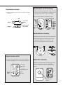
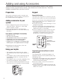
1
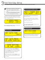
Easy Fit Touch Screen
alarm system (EF-Panel)
Installation · Programming · Operating
Keep this manual safe for reference and future maintenance
Introduction
Contents
Thank you for choosing the Yale Wireless Alarm System.
This simple to install system has been designed with the
user in mind.
Contents
All the components are self contained and no connections
are needed between the units. There is no need to
damage the home decor, lift carpets or run cables.
You can install up to 20 devices in this system. As well as
extra door/window contacts, PIRs and smoke detectors,
you can add keyfob remote controls and keypads for
added control convenience.
There is no need to wire into the mains supply or seek
the services of a qualified electrician. The control unit is
powered by a plug top supply and all other components
are powered by battery (all batteries included).
Batteries will operate for 2 years or more before they need
changing. Regular testing and battery changes (when
notified by the system) will ensure reliability and peace of
mind.
The security detectors, control panel and external siren
are ‘tamper’ protected. Any unauthorised tampering with
these items will result in an alarm. This feature can be
turned off by the user when a battery change is required.
Display extreme caution when using ladders or steps,
please follow manufacturer’s instructions.
Be careful when using hand and power tools and follow
the manufacturer’s guidelines when using them. Take care
that the correct tools are used. Wear goggles or protective
clothing where required.
The external Siren is extremely loud, please ensure you
replace the cover and retreat to a safe distance before
testing.
1 Location planning
2
2 Unpack all the parts
4
3 First Time Easy Install
6
4 Mounting alarm devices
8
5 Control Panel Menu System in Detail
11
6 Using the System17
Adding and using Accessories
20
Changing the batteries
22
Troubleshooting
24
27
Sensor response table
Specifications
28
Recommended Installation Sequence
We recommend you follow the simple install
sequence, headings numbered 1-6.
The dialling facilities must only be used with persons who
have consented to being contacted by the system.
The system is not to be used to make 999 emergency
calls directly. Yale do not hold responsibility for any actions
taken by emergency services for incorrect use of the
dialling facility.
Special Notes on Compatibility:
This alarm system is NOT compatible with SmartHome
Alarm, HSA6000 series and HSA3000 series accessories.
Please note the prefix “EF-” on the front of the part
number to indicate compatibility.
Information and illustrations are subject to change within this
document. Yale reserves the right to alter the specification and
product design at anytime without notice. Yale® is a registered
trademark. © 2012 ASSA ABLOY. All rights reserved.
1
Location planning
Work out the best places to locate the devices for maximum protection. Having chosen the
locations do not mount at this stage.
Home and Away Mode Planning
The home arming mode allows the premises to be
part armed so that no one can get inside without
warning the occupier, yet the person already inside
the house can move freely without triggering the
alarm. For example the downstairs of a house can
be armed while upstairs can be disarmed allowing
the user to go to bed without causing an alarm.
If this feature is to be used, then it should be
planned now, before installation.
Decide what areas can be occupied when in home
arming mode, the sensors for these areas should be
ignored using the “Home-arm set” option (see page
11); and the sensors activated on the path to access
the control unit should be to be set to either Entry or
Away Entry as explained in Chapter 5.
Keypad remote control accessory
When used as second keypad, it is ideal in
bedrooms or at the top of a stairwell so the
ground floor can be armed when going to bed
for the night. Or, at a side or back door for
alternative entry.
•Mount at chest height for ease of use
•Designed for indoor use only
•Keypad should be accessible from a protected
entry/exit point
•Ensure that the keypad is not visible from the
outside of the premises.
Operating Range
All devices must be within 30 metres of the control
unit and must not be mounted on or near large
metal objects. Avoid obvious sources of electrical
interference such as fridges and microwave ovens.
Yale
Yale
When mounting devices ensure that any tamper
switches close fully. On uneven surfaces it may be
necessary to place packing behind the switch for
reliable operation.
Extend The System
Extend the system in the future to increase your
security or as your needs change.
For example, add extra PIR detectors and
extra door/window contacts.
Choosing Location
Help button accessory
The help button provides extra protection for you
and your family. When help is needed the button
can activate your alarm immediately - even when
the system is disarmed.
•Mount on flat wall surface
•Designed for indoor use only
•Out of reach of children
•Hidden from view while easily accessible.
2
2
3
4
5
6
7
8
9
0
Tamper Switches
To minimise interference, avoid locating devices
close to metal framework, glass, electrical
appliances (especially wireless devices) and electric
cables.
Please note that the present of high density material
(metal, glass etc) in the transmission path will
significantly reduce the wireless transmission range.
1
Smoke detector
• Mount in the middle of the ceiling at the top of
a stairwell, or on the centre of hallway ceilings
where smoke would most likely be detected.
• Do not mount in corners or above cooking
appliances and heaters.
• Install additional detectors if there are closed
doors preventing smoke from reaching
detectors.
Siren
Choose a position on an external wall where the
siren would be most prominent. Mount as high as
possible, out of easy reach.
Door/Window contact
Select a door that will be the main point of entry
and exit, usually your front door.
• Mount as high as possible
• Do not aim a PIR at this door or window
Yale
1
2
3
4
5
6
7
8
9
0
Y a le
Yale
Yale
Keyfob remote control accessory
Can be used inside or outside the property and
can be kept on your keyring.
Y a le
Yale
Text Display
PIR movement detector
• Mount in a position such that an intruder would
normally move across the PIRs field of view.
• Height should be between 1.9 and 2 metres
above floor level.
• Location in a corner will ensure wider room
coverage.
• Do not mount the PIR where its field of view will
be obstructed e.g. by curtains, ornaments etc.
• Do not point directly at sources of heat e.g. fires
or boilers, and do not position directly above
radiators.
• Avoid mounting the PIR directly facing a
window.
• Do not point the PIR at a door protected by a
door/window contact.
Control unit
• Ensure it is hidden from view while accessible.
• Access to mains socket and telephone point.
Text Display
3
2
Unpack all the parts
Backspace/Return
Up
Down
Siren
OK
WARNING
Siren
The siren is very loud, be prepared! Take care not to
activate the siren tamper switch unnecessarily.
Text Display
1 Remove the cover by unscrewing the single screw
located on the lid.
Power LED
2 Power switch to ON position.
Fault LED
Microphone
Menu
Arm
Home Arm
Disarm
Numeric
keys
Control unit
Unpack the kit content on a table. Remove the
mounting plate (if fitted) from the control unit by
sliding plate downwards. A power adaptor is
supplied that plugs into the main wall socket and
control unit. Do no plug in at this stage, this will be
done at Section 3.
PIR movement detectors
1 Pull out the plastic pull tab on the back of the PIR.
This will activate the batteries.
Plate
• In addition to the adapter, there is a rechargeable
battery inside the control unit that serves as a
backup in case of a power failure. A fully charged
battery can provide backup power for a period
of at least 10 hours. It takes approximately 36
hours to fully charge the battery. The control unit is
equipped with a backlit LCD display and keypad
for easy operation in the dark. To conserve backup
battery duration the backlights will be switched off
during mains power failure.
•Remove the rubber battery switch cover and
locate the battery switch to the right in the
direction of the arrow to switch the internal battery
“on” and replace the rubber cover.
4
Yale
Status
LED
Learn/Test
Button
Cover
screw
Keyfob remote control accessory
Door/window contacts
1 Pull out the battery saver tab on the side to activate
Keypad
remote control
the battery.
Yale
Remove the cover and insert the 3 AAA alkaline
batteries as shown. The ‘Tx’ LED will flash briefly
while components initialise.
Please note, the HomeLED
button on the operating
panel and the jumper switch inside (do not move)
Learn/Test
have no function on this model.
Sensor
1 Open the battery compartment using a coin by
turning cover in the direction of the big arrow so
Keyfob
remote control accessory
the cover small arrow is next to round dot.
Slide off the battery cover, insert the
223A/MN21
Insert CR2032
battery
and replace
cover.
battery
as shown,
and replace
battery cover. Switch to ‘on’.
On/Off switch
button
/
Gap no more
than 10mm
Magnet
Smoke detector accessory
1 Remove the cover and insert three AA batteries
Jumper
switch
Tamper
switch
detector
accessory
2Smoke
The Smoke
detector
will now enter into selfcalibration mode for 15-20 minutes. It will
Remove
the cover
and insert
theperiod.
four AAA
resume
normal
operation
after this
batteries as shown.
Learn/Test
Button
Door/window contacts
1 Remove the cover of each door/window contact
by loosening the fixing screw.
2 Insert two AAA batteries into each detector as
shown. The indicator LED will flash briefly.
Keypad remote control
LED
Yale
Learn/Test button
Extension terminals
1 Pull out the plastic battery saver tab at the back of
the remote keypad. This
will activate the batteries.
Tamper
switch
Jumper
switch
Yale
Magnet
/
1
2
3
4
5
6
7
8
9
0
Learn/Test
button
Panic button A
Panic button B
LED
Help button accessory
Help button accessory
Remove the cover by loosening the fixing
Remove
the insert
cover by
the (supplied)
fixing screw
screw and
theloosening
12V battery
as
and
insert
the
CR2032
battery
(supplied)
as
shown. Please ensure you observe battery
shown
(1). Please ensure you observe battery
polarity.
polarity.
Learn button=
Press 8 and 9 together
1
Disarm
HomeArm
Panic/Learn
button
57
3
First Time Easy Set-up
The installation guide will provide you with prompts to easily set-up the system.
i
• Any omissions or mistakes can be rectified later. Once the first time install has been successfully completed it will not be shown again.
• More advanced programming can be done at a later stage including adding and naming sensors and changing various settings.
Connect the mains power adaptor to the control
panel (in the intended location). After the welcome
screen, the display will show:
3 Steps easy
setup (ok?)
Press OK (3) to continue. You are 3 steps away
from completing the initial set-up.
2. Set the phone number to alert
Set 1 phone num
for alert (ok?)
Enter a phone number to be alerted in the
event of an alarm.
Press “Up arrow” key for * key (3 seconds
time gap, useful for switchboard) and “Down
arrow” key for the # key.
Press OK (3) to continue.
Press Return button to skip if you do not want
any alert through the phone.
3. Set the Pincode
1. Set Time/Date
Set date/time
(ok?)
Press OK (3) to continue.
Set date,press
ok when done(ok)
Press OK (3) to continue.
date setting
01 jan (pqOK)
Set the current month using the p/q key.
Press OK (3) to confirm setting. Set the day
using the p/q key. Press OK (3) to confirm
setting. After setting the day, it will now
prompt you to set the time.
Set the current time using the p/q key. Press
OK (3) to confirm the hour, follow by setting
the minutes.
6
Set pin code
....
Enter the four digit pincode you would like to
use (e.g. 1234). Press OK (3) to continue.
Next, the screen will display:
.Exit setup
Repeat Setup
Upon selecting “Exit Setup”, you will now be
prompted with:
mount devices,
see Manual
Please leave it on this screen and proceed to
mount all your devices (see Chapter 4).
Note: If a different prompt is shown, please see
section on the right.
Error Condition
(Upon selecting Exit setup)
If there are no device/accessory (accidentally
deleted) in the system and you selected “Exit
Setup”, you will be prompt with “Please add at
least one device”.
i
Please add at
least one device
If you see this message, please press the test/
learn button on all your accessories (including
the Siren) one at a time.
Every time a button is pressed, the screen will
prompt the device and you will need to press OK
on the panel to acknowledge/add. It would then
be reverted to the “Exit Setup, Repeat setup”
screen. Please press the learn button on the
next device and repeat the above steps. Please
ensure all the devices are added one by one.
Choose “Exit setup” once everything is added.
Alternatively, should you wish to finish initial setup
with no device learnt-in, you can force exit by
pressing disarm and then followed by the pincode.
You will now be prompted with:
mount devices,
see Manual
Please leave it on this screen and proceed to
mount all your devices (see Chapter 4).
7
4
Post Installation/Mounting Devices
Note: Tamper is disabled during initial set-up. For details on disabling tamper see Section 6
Control Unit Mounting
Wall Mounting
Using the two holes on the mounting back plate,
mark the position of the holes. Drill two holes and
fix with the screws and plugs provided. Hook the
control panel onto the plate. Ensure that the control
unit is fitted at approximately chest height where
the display can be easily seen and the keypad
convenient to operate.
•The control unit tamper protection will
automatically arm when mounted on the back
plate.
NOTE: At this point, the control panel
screen should be showing:
mount devices,
see manual
Mounting other devices
Find a location where the device is to be mounted,
see section “Location Planning” for suggestions.
Before proceeding to mount the devices physically,
check that the control unit will receive the system
radio transmissions by doing a simple radio range
test.
Please make sure the control unit screen is
displaying:
mount devices,
see manual
Hold the devices in the desired location and press the
Test/Learn button (see below) on the accessories.
• KEYPAD: press button 8 + 9 together.
• ALL OTHER DEVICES: Hold the device in the
desired location and press the learn/test button,
the control unit should respond with a chime.
If the sensor signal reached the control unit, the
screen will briefly display:
8
dc zone01 b
........
6
*Note: this screen shot is use as example only.
The radio signal strength is shown by a number on
the upper right (6 in this case). this number ranges
from 1 to 9 (strongest). Where possible please ensure
sensor shows 5 or above for optimal performance.
When you are happy that all your devices can
communicate with the panel, press the Green
“Disarm” button and enter your pincode that you
previously defined. The screen will now show:
Alarm Off
00:00 01 jan
Leave it at this screen and proceed to mounting the
accessories as detailed below. The fault light/beep
maybe activating periodically and you can ignore that
until you finished mounting.
Mounting the siren
Ensure the tamper switch is fully depressed when
the siren is mounted. If there is a gap, pack with a
suitable spacing material.
Spring compressed
firmly against wall
Round
Siren
Base
Wall
Spring Guide
1 Using the large screws and wall plugs provided,
screw the siren onto the wall through the 4
mounting holes on the siren base.
2 Fix the siren cover with the securing screw.
Mounting the PIR
1 Open the PIR by loosening the bottom screw.
Knock out the relevant holes on the base where
the plastic is thinner. The center two knockout
holes are for flat wall mounting while the 4 side
holes are for corner mounting.
1 Find a location on the door/window where you
would like the device to be mounted. The sensor
should be on the frame while the magnet should
be on the door/window. Once mounted make sure
the tamper switch spring is fully depressed.
gap between the magnet and sensor should
i The
be no more than 10mm when closed (maybe
Battery tab
Wall fixing
knockouts x2
Corner fixing
knockouts x4
2 Drill holes into the wall using the knockout holes on
the base as a template.
3 Fit wall plugs and secure the PIR base with the
screws provided.
4 Fit the PIR back together and tighten bottom
screw, the PIR installation is complete.
Mounting the Keypad:
Battery Saver tab
Wall Fixing
knockouts x2
1 Knock out the fixing holes. Drill holes into the wall
using the fixing holes as a template.
2 Fit wall plugs into the wall and fix back cover with
the screws provided. Fix front of the keypad onto
the back plate.
Mounting the Door Contact
shorter depending upon the actual environment).
Simple test to see whether the magnet is in range
of the sensor: hold the magnet and sensor in
place and then pull them apart. If the sensor LED
lights up it implies the two items are within range.
-Mounting using adhesive pads
Clean the mounting surface with a suitable
degreaser agent. Please note that some surface
or environment (i.e. exposure to Sunlight) maybe
unsuitable for this mounting method. Please use
screw mounting in these cases.
-Mounting using screws and wall plugs
Loosen the bottom screw
and open the door/window Knockouts
contact. Knock out the holes
on the base as shown. Drill
holes into the mounting
surface using the holes in
the knockouts on the base
as template. Fit wall plugs
(if required) and secure with
the screws provided.
Mounting the Help button
1 Break through the knockouts (where the plastic is
thinner).
2 Using the holes as a template, drill holes in the
surface and insert wall plugs if fixing into plaster or
brick. Screw the rear case to the wall.
Frame
3 Replace the cover and tighten the screw.
Door/Window
Sensor
Mounting the Smoke Detector
1 The base has two mounting slots. Using the slots
as a template, drill holes and insert the wall plugs if
fixing to plaster. Screw the rear case to the ceiling
using the screws provided.
Yale
Magnet
Sensor
Gap no more
than 10mm
2 Replace the main unit onto the bracket.
9
About your alarm system (default settings)
All accessories were pre-set to
“entry” attributes.
i
To change the property of individual sensor (i.e.
Burglar attribute where the individual sensor will
instantly alarm when triggered), see Chapter 5,
Devices, Edit Devices.
When the system is first armed, user will have 30
seconds to exit the building. System will ignore any
sensors triggering in this duration.
Home arming is disabled by default. If you need
Home arming function, see Chapter 5, Homearm set.
If the system is already armed, triggering any
sensors will cause an entry countdown to begin.
When the alarm is triggered, the
system will dial out to alert the
owner.
i
To set up more telephone numbers (maximum
3 in total), please see Chapter 5, Tel. Settings.
When the alarm alerts you via
telephone, it will playback the
address message: “Yale Alarm
System” follow by the specific
event message (i.e. burglar).
i
You can record a custom address
message that will be playback before the
event message. Please see chapter 5, Tel.
Settings
Siren length is set to 3 minutes.
i
To change, please see Chapter 5, Adv.
Settings, Alarm Length.
i
You can prevent arming when door contact is
opened. Please see Chapter 5, Adv. Settings,
DC Open/close.
i
To change and allow disarming the system
(using keyfob) prior to you entering the building,
Please see Chapter 5, Adv. Settings, KF Entry.
i
If Jamming and interference is of concern,
please see Chapter 5, Adv. Settings, Jamming
Det for option.
As default, it is possible to arm
the system with “open” Door
contact (i.e. windows open).
When using a keyfob, you will
need to trigger the entry timer
(triggering a sensor) before you
can disarm the system with the
keyfob.
Jamming and interference
detection disabled as default.
10
To change the exit and entry timer, see Chapter
5, Adv. Settings.
5
Control Panel Menu System in Detail
System Test
Entering Programming Mode
The programming mode is for you to configure
the system, and make any changes to the pre-set
functions.
If the system is in Disarmed (Alarm off) mode, follow
the steps below to enter the programming mode.
1Press ‘menu’
key on the control panel.
The screen will prompt you to enter the PIN code.
P - M o d e
P - C o d e
e n
. .
t
.
e
.
r
2Key in your PIN code within 30 seconds.
Note
• Press P to clear the entered PIN. If the code field
is empty, it will return to the Alarm Off screen.
3Press 3 to continue.
The following message is displayed for 2 seconds.
P r o g
M a k e
a
r
a m
m e n u
s e l e c t i o n
4Then the Programming Main Menu will typically be
displayed.
* S y s t e m
t e s t
H o m e - a r m
s e
t
Note
•The cursor is indicated by a flashing dot on the left
upper corner. It can be moved up and down by
pressing pq respectively.
5The following items can be selected:
· Fault log (only if there is a fault condition)
· System Test
· Home-arm set.
·Devices
·Log
· Adv. Settings
· Tel. Settings
6After making a selection by moving the cursor
to the desired item, press 3 to confirm the
selection. The display will show you the individual
programming screen accordingly. Selecting P will
return to the Alarm Off screen.
Important Note
•In programming mode, if no key is pressed within
5 minutes, the panel will exit the programming
mode and return to the Alarm Off screen.
When System Test is selected, you will be given 4
different options: Sensor Test, External Siren (test),
Panel Siren (test) and Phone alert.
Sensor Test:
three beeps will sound during a screen self test. This
allows you to test the system without causing an
alarm. To test the control panel is receiving a signal,
do one of the following depending on the device:
1Press button 8 and 9 together on the keypad
2Press the test/learn button on the sensor
3Press the help button
A chime will sound and the display will show you
which device is transmitting.The upper right corner
will show the radio signal strength ranging from 1 to
9 (strongest). Relocate the sensor if this is below 5
(unstable).
Ext. Siren and Panel Siren (test):
•The external siren and control unit (panel) siren can
be tested by pressing 3 when prompted. Press 3
once more to stop the siren.
Phone alert:
•Select this option for a test call via phone dialer.
Home-arm set.
The home mode allows the home to be partially
armed so that no one can get inside without first
disarming the system. However, the person inside
the house can move freely around without triggering
the alarm. Home mode is usually used to protect the
ground floor when you are upstairs in bed.
To enable home arm, you will first need to choose
the sensors to be ignored during this mode. It would
typically be the bedroom PIR etc if you want to arm
your system during the night.
Selecting this option, the screen will display:
Press test on
sensor to ignore
11
If you press any test/learn button on any learnt-in
sensor (confirm by pressing 3), these sensors will be
ignored during the Home Arm mode.
Repeat this step to ignore additional sensors.
Devices
Select ‘Devices’ in the main programming menu to
add or remove a device. From here you will be able
to view a list of all the devices being installed and
you can add or delete devices. The following items
can be selected.
· Add Device
· Edit Devices
· Remove Device
· Program Siren
Add Devices
1To learn-in a new device select ‘Add Device’
then press 3, a “push Button on Device to Add”
message will be shown.
2Press the learn button on the device within 30
seconds (see Chapter 2 for location).
3If a signal is detected, the screen will show the
type of device found.The upper right corner will
show the radio signal strength ranging from 1 to 9
(strongest). Relocate the sensor if this is below 5
(unstable).
• Devices are labeled by the following codes within
the control unit:
· Door Contact DC
· PIR Sensor IR
· Smoke Sensor SD
· Remote Keyfob RC
· External Siren BX
· Remote Keypad KP
· Help Button FP (Fix-Panic)
• When a sensor is added to the system for
a second time, an error “Already in System”
message will be briefly displayed and the control
unit will wait for another learn-in signal.
4Press 3 to confirm the device type.
5The following zone types will need setting for door
contacts and PIRs:
· Burglar
12
· Home Omit
· Entry
· Away Entry
· 24 Hour (DC only)
The following devices have a fixed emergency
zone type:
· Smoke Detector
· Remote Controller emergency Button
· Help Button
· Remote Keypad dual emergency buttons
· Control Unit dual key emergency (1 and 3) keys
Zone Type List
Burglar
• When the system is in home or away armed mode
and a burglar device is triggered, a burglar alarm
will be activated immediately.
• A device set to burglar will not trigger an alarm
during entry or exit delay periods.
Home Omit
• A home omit device will be ignored when the
system is home armed.
• A home omit device will give a burglar alarm when
the system is away armed.
Entry
• If an entry device is triggered when the system is
either away or home armed, it will start an entry
delay period to give enough time to disarm the
system.
• If the delay period expires without being disarmed,
the control panel will respond with a burglar alarm.
• If the device has been set to entry and triggered
when the system is in disarmed mode, the control
unit will make a ‘ding-dong’ door chime sound if
the door chime feature is enabled.
Away Entry
• If an away entry device is triggered when the
system is in armed mode, the control unit will
start an entry delay period to give enough time to
disarm the system.
• If the delay period expires without being disarmed,
the control panel will respond with a burglar alarm.
• An away entry device is ignored when home
armed.
• The device will not give a “ding dong” chime sound
when door chime is selected.
24 Hour
• The door contact is the only device that has this
zone type, the PIR does not.
• A 24 Hour door contact is active all of the time
and does not have to be armed or disarmed,
if triggered a burglar alarm will be activated
immediately.
Emergency
• An emergency device is active all of the time does
not have to be armed or disarmed, if triggered an
emergency alarm will be activated immediately.
Edit Devices
To edit all of the devices that has already been
installed, choose ‘edit devices’ in the device +/menu. All of the devices included in the system will
be displayed.
1 Use st keys to scroll the display and choose the
device for editing. Press 3 to select. Depending
on the device a list of zone types will be given,
otherwise you will be asked to enter a name.
2 If available select a zone type and press 3 to
confirm.
3 After confirming the zone type (if available), you are
now asked to enter a name. Press 3 to confirm or
P to cancel without naming.
Device Naming
• Each device can be given a 12 character name.
Names can be given either when first adding a
device or by editing them later.
• When the “Enter New Name” screen is displayed
the numeric keyboard can be used to enter text.
Simply find the corresponding numeric key with
the required character and press repeatedly until
the wanted character appears. Release the key
and the flashing cursor automatically jumps to
the next position for you to continue with the next
character by the same method.
• The keys have the following functions:
1 1
2 2ABCabc
3 3DEFdef
4 4GHIghi
5 5JKLjkl
6 6MNOmno
7 7PQRSpqrs
8 8TUVtuv
9 9WXYZwxyz
0 0 <space>/&’.”+
P Backspace and delete
• The name can be erased by clearing the display by
pressing P repeatedly, followed by 3.
4 Press 3 when completed to confirm the name and
return to the device list.
Remove Device
To delete a device choose ‘remove device’ in the
“Edit device” menu. A list of all programmed devices
will be shown.
1 Use st keys to select the device you wish to
delete and press 3.
2 The selected device will be displayed again, press
3 to confirm deletion or P to return to the device
list without deleting.
• If a device name has not been programmed the
screen will show the preset zone number instead.
Program Siren
To program the siren, select ‘program siren’ in
the “Edit device” menu. The following items are
available in this menu:
• Siren Tamp. On
• Siren Tamp. Off
• Confirm On
• Confirm Off
• Entry Snd On
• Entry Snd Off
• Comfort LED
Siren Tamp. On, Siren Tamp. Off
The siren tamper switch can be enabled and
disabled remotely.
• The siren tamper protection automatically switches
back on after one hour.
Confirm On, Confirm Off
The siren can be enabled for arming and disarming
confirmation where one pip and flash is given for
arming, with two pips and flashes from side to side
for disarming.
Entry Snd On, Entry Snd Off
The entry and exit warning beeps can be echoed on
the siren.
Comfort LED
If enabled, the siren LED will flash periodically
according to the set interval. This will reduce the
battery life accordingly. Select disable to disable this
function (Default Off).
13
Log
The alarm log memorises the last 30 system events
including:
· All alarm events with device names and type
· All fault warning events
· All arming and disarming events
• The logged events are displayed in reversed
chronological order (most recent event first).
• The log is marked with a ‘start’ label before the
most recent entry and ‘end’ after the oldest entry.
To view log:
1 Select the Log menu and press 3.
2 The log can now be scrolled up and down and
viewed with the st keys; the most recent event
will be at the start.
3 The first line displays the time and date of the
event, the second line displays the type of event
and the third line either states the user or the
device that caused the event. Abbreviations used
are:
· “LB”: low battery
· “Tamp”: tamper
· “R”: restore.
· AC: mains power
· Panic: emergency
· Perimeter: entry or away entry device
· Cancel: silencing an alarm with a help button
Pin Code
The PIN Code (password) is used to configure the
control unit and to disarm the system.
• To disarm, press the ‘disarm’ key followed by your
PIN code.
• To enter the program menu press the ‘menu’ key,
enter a PIN code followed by 3.
• Up to 4 Pin codes can be stored.
1 Select ‘Pin Code’ then press 3, a list of 4 PIN
codes will be shown, occupied codes are shown
with ****. The list can be scrolled up and down
using thest keys.
2 Select the code you want to change and press
3, enter your new PIN code and press 3. You will
be asked to repeat the PIN code, enter it again
and confirm by pressing 3, the new code is now
programmed.
Adv. Settings
• P can be used to correct entry errors, pressing P
repeatedly will return you to the PIN code list.
• User 1 code can only be changed and cannot be
erased. All other codes can be erased by selecting
them and pressing 3.
• An error message will be shown if either an
incorrect repeat code is used or a duplicate code
is entered for another user. All codes have to be
different.
The following items are available in this menu:
Entry Time
The settings will initially have factory default values.
If you do not want to change them then you can
escape any menu by pressing P without making
changes.
14
· KF Entry
· Tamper Alarm
· Mobility CHK
· Siren Delay
· Warning Beep
· Time
· Date
· Supervision
· Pin Code
· Entry Time
· Exit Time
· Entry Sound
· Exit Sound
· Door Chime
· DC Open/Close
· LCD Backlight
· Key Tone
· Ring Tone
· Alarm Length
· C.U. Siren
· Jamming Det
Note: Ensure device is set to entry on control unit for
the entry time to work (see section 5, Add Devices)
Entry time gives you a delay to allow you time to
enter your premises and disarm the system. Times
can be set from 00 seconds (no delay) up to 70
seconds in 10 second increments.
• 20 seconds is the factory default.
Exit Time
Entry time gives you a delay to allow you leave you
premises before the system arms. Times can be set
from 00 seconds (no delay) up to 70 seconds in 10
second increments.
• 30 seconds is the factory default.
Entry Sound
The control unit will beep during the entry delay
period as an entry warning, you can switch the
sound on and off with this setting.
• Entry sound on is the factory default.
Exit Sound
The control unit will beep during the exit delay period
as an exit warning, you can switch the sound on and
off with this setting.
• Exit sound on is the factory default.
Door Chime
Any door contact or PIR set to entry will cause
the control unit to chime when activated when the
system is disarmed. This is used to signal when
anyone has entered your premises. You can switch
the sound on and off with this setting.
• Chime off is the factory default.
DC Open/Close
If this is turned On, the control panel will sound a
door chime and display a fault message when user
tries to arm the system with Door contact opened.
• DC Open/Close Off is the factory default.
LCD Backlight
The control unit display LCD can be turned on
Permanently or set to auto turn off after 30 seconds
of last key pressed.
• Auto off is the factory default.
Key Tone
The control unit can be made to beep when a key is
pressed. Key Tone can be selected to On or Off.
• Key Tone On is the factory default.
Ring Tone
The control unit can be made to beep when the
phone is ringing, you can switch the sound on and
off with this setting.
• Ringing off is the factory default.
Alarm Length
The siren (both external and built-in) will sound when
an alarm is activated. The length of the alarm can be
set from 1 to 10 minutes in 1 minute increments with
this setting.
• 3 minutes is the factory default.
C.U. Siren
You can disable the control unit’s built-in siren with
this setting.
• Siren on is the factory default.
Jamming Det
Enable or disable Jamming/Interference detection on
the control panel. Confirmed by pressing the 3 key.
Default setting is Disable (recommended).
KF Entry
When selected as Off, user must first trigger an entry
sensor before the keyfob can disable the system.
Please select On if you which to disarm the system
without first triggering an entry sensor.
• KF Entry Off is the factory default.
• If the Keyfob’s Panic button is triggered, the
same keyfob cannot be use for disarming the siren.
Tamper Alarm
If set to Away Arm only, it will trigger the alarm when
tamper is active under away arm mode (also known
as full arm). It will only give a fault LED indication in
all other mode. If set to Normal, a tamper condition
will always triggers a burglar alarm under disarm,
home arm and away arm mode.
• Away Arm Only is the factory default.
Mobility CHK (for elderly or infirm)
If there is no movement around the house for a
preset period of time (from home omit sensors under
part arm and all sensors under disarm mode), an
emergency alarm will be activated and reported over
the telephone line. Any key presses on the panel
and entry sensor triggering will reset the countdown
timer. The monitoring can be disabled or set at 4, 8
and 12 hour.
• Disable is the factory default.
Siren Delay
This setting allows a delay before the control unit
and external sirens are activated. You might want to
use this if you do not want the control unit to draw
attention to itself during an alarm, to give it time to
dial out on the telephone line. The delay can be set
from Disable (no delay) to 10 minutes in increments
of 1 minute.
• Disable is the factory default.
Warning Beep
The control unit will give a reminder beep every 30
seconds in the event of a system fault, such as
tamper or a low battery etc. This setting allows this
feature to be switched on and off.
15
• Warning on is the factory default.
Time
The control unit uses a 24 hour clock. The time
is set by using the pq keys and confirmed by
pressing the 3 key.
Date
The day and month are set by using the pq keys
and confirmed by pressing the 3 key.
Supervision
Enable or disable supervision detection on the
control panel. PIR, Door Contact, Smoke Detector
and Siren can be monitored for outage using
this feature. Except for Smoke Detector (which is
always on), the other three accessories need to
have supervision enabled on board to facilitate this
feature.
• Default setting is Disable (recommended).
Tel. Settings
This menu allows you to program up to 3 telephone
numbers, record an address message and place
test calls, The following items can be selected.
• Tel. Numbers
• Rec. Address
• Test Report
Tel. Numbers
This menu has a list of 3 telephone numbers. These
numbers are dialed in order, a maximum of 20 digits
per number can be stored. Only one number is
required to enable the control unit to report over the
telephone line.
1 Use the pq keys to select a number from the list.
2 Press 3 to confirm. If there was a number already
stored then you will be asked to change the
number, if the slot was empty you will be asked to
enter a new number, confirm by pressing 3.
3 Enter your phone number and confirm by
pressing 3. Press “Up arrow” key for * key (insert
3 seconds time gap, useful for switchboard) and
“Down arrow” key for the # key.
• Errors can be corrected by pressing P to
backspace, pressing P repeatedly will take
you back the telephone number list. Telephone
numbers can be deleted in the same manner.
16
Rec. Address
This menu allows the recording of your address.
The maximum length of message is 10 seconds
which is ample for most messages, when recording
remember to speak clearly and slowly into the
microphone.
1 Press 3 and you will be either asked to record a
new message or change an old one.
2 Press 3 again and follow the on screen
instructions. When you finish recording remember
to press 3 to stop recording. If you go over the
10 second recording time (indicated by a beep)
just repeat the recording procedure again taking
care not to go over the 10 second time limit. The
recording is complete.
Test report
This menu allows you to test the telephone reporting
feature.
• Please check with the call recipients before making
a test call.
• Ensure that the phone cord is connected.
1 Select Test report and press 3.
2 A list of numbers will be displayed, select the
number you want to test and press 3.
3 The control unit will now display call progress.
• The address message and pre-recorded
emergency, burglar and acknowledgement request
messages will be played in a loop for 85 seconds.
• The test can be cancelled at any time by either
pressing the P button or the call recipient pressing
“9” on their phone to acknowledge the call. If a
radio DECT or mobile phone is used, remember to
press 9 repeatedly until the call closes.
• Check that the call has been successfully received.
6
Using the System
Arm and disarm the system and practice using it. Trigger the alarm by arming the system and
opening protected door/windows and walking past PIRs. Now is the time to show the rest of
the family how simple it is to use.
PIRs have a built-in sleep timer to save
i The
battery power. If there is no movement in front
of the PIRs for 1 minute, the PIRs will become
‘ready to signal’ and movement will now be
reported. The PIRs will sleep for 1 minute after
reporting.
Any movement detected in sleep time will not be
reported and will extend the sleep period by a
further 1 minute.
Away Arm
Arming the System
1When the system is disarmed (alarm off), press the
arm key on the control unit, keypad or keyfob.
2The control unit will start its countdown.
3When the exit delay time is up, the control unit will
sound a long beep. The siren will beep once and
the strobe will flash once after the exit delay has
expired. ‘Alarm on’ will be displayed on the screen
and the system is now in away armed.
4If there are faults within the system, i.e. the tamper
switch of a sensor left opened, the user will not be
able to arm the system with a single press. The
user can use the control panel, keypad and keyfob
to force arm the system by pressing arm twice.
1Press the disarm key on the keyfob or press the
disarm key followed by a PIN code on the control
unit and keypad.
•The keyfob only will only disarm the system during
entry time after an entry or away entry door/
window contact or PIR has been triggered.
2 The control unit will sound a long beep. The siren
will beep twice and the strobe will flash side to
side. ‘Alarm off’ will be displayed on the screen
and the system is now disarmed.
3 The control panel will lock out for 5 minutes if
the pincodes had been entered incorrectly for five
times.
Home Arm
The home mode allows the home to be partially
armed so that no one can get inside without first
disarming the system. However, the person inside
the house can move freely around without triggering
the alarm. Home mode is usually used to protect the
ground floor when you are upstairs in bed.
Arming in Home Mode
•The exit delay time can be extended during the
exit delay period by pressing the arm button on
the keypad or keyfob. Each time the arm button
is pressed, the delay time starts counting from the
beginning.
1When the system is disarmed (Alarm off), press
the home arm key on the control unit, keypad or
keyfob.
2The control unit will start its countdown.
3When the exit delay time is up, the control unit
will sound three short beeps. The siren will beep
once and the strobe will flash once after the exit
delay has expired. ‘Home’ will be displayed on the
screen and the system is now in home armed.
4If there are faults within the system, i.e. the tamper
switch of a sensor left opened, the user will not be
able to arm the system with a single press. The
user can use the control panel, keypad and keyfob
to force arm the system by pressing arm twice.
Alarm Activation
Extending the Exit Delay
Stopping the Exit Delay by Disarming
1Press the disarm key on the keyfob or press the
disarm key followed by a PIN code on the control
unit and keypad.
2 ‘Alarm off’ will be displayed on the screen and the
system will return to disarmed mode.
Extending the Exit Delay
•If any Door/Window contact or PIR sensor set to
entry or away entry is triggered, the entry timer will
be started. If the entry timer is allowed to expire
and alarm will be activated.
•If other sensors not set to entry or away entry is
triggered, the alarm will be activated immediately.
Disarm
Disarming the System
•The exit delay period can be extended in a similar
manner as described in Away Arm.
Alarm Activation
•If any door/window contact or PIR sensor set to
entry is triggered, the entry timer will be started. If
the entry timer is allowed to expire and alarm will
be activated.
•Home omit and away entry sensors will be
ignored.
•If other sensors not set to home omit, entry
17
or away entry are triggered, the alarm will be
activated immediately.
Stop the Alarm and Alarm
Display
During an alarm, the control panel and outside siren
will sound and dial the emergency phone number.
The control unit will display “ALARM! ALARM!” to
notify the user.
Stopping the Alarm
1Press the disarm key and enter a user code on the
control unit or keypad. The control unit will sound
a long beep and display the device that caused
the alarm. The siren will beep twice and the strobe
will flash side to side.
•The keyfob cannot stop an alarm caused by
burglar or emergency device.
2 When the control unit is displaying the source
of the alarm, pressing any key will display
the telephone number that it dialled out and
acknowledged (if any). If there were more than 2
numbers that were acknowledged the numbers
will be shown by pressing further keys.
3When “Alarm off” is displayed the system is
disarmed.
Alarm Memory
•If an alarm was raised during your absence, and
the alarm sequence has been carried out, the
screen will continuously show “ALARM! ALARM!”.
•Disarm the system as normal and the siren will
give 3-second alarm sound instead of the normal
two beeps to indicate that there might still be an
intruder still in the house.
•To clear the display, follow the same steps as
‘Stopping the Alarm’ described above.
Dialling & Call Acknowledgement
Auto Dialling
18
•If the system is in away arm mode, when an alarm
occurs the control unit will immediately dial the
preset phone numbers.
•If the system is in home mode or disarmed mode
when an audible alarm is initiated, the control unit
will wait for 15 seconds before dialling the preset
phone numbers.
•After dialling, the control panel will wait 5 seconds
then playback the messages in a loop. It will first
play the recorded address message then the
pre-recorded messages (Burglar, Emergency)
depending on the nature of the alarm and finally an
acknowledgement request message.
•The recipient should acknowledge the message by
pressing ‘9’ on their telephone when prompted.
•Recipients using radio DECT phones or mobiles
should press the numbers repeatedly until the call
is closed.
•If the control unit does not receive an
acknowledgement, the messages will be repeated
for a period of 80 seconds before attempting to
dial again. Each number will have 5 call attempts.
•The control panel will continue to dial the
number(s) until a call is successfully answered with
a ‘9’ acknowledgement.
•System auto-dialling features only operate under
tone-dialling method.
•When no telephone number is stored, the control
panel will not dial out.
Remote Access
The control unit allows you to control your system
remotely through the telephone line.
1Dial the phone number associated with the Control
panel.
2Hang up on the first ring.
3Wait 5-10 seconds.
4Dial the number again.
5The control unit will answer the phone on the first
ring of that second call.
6Enter your PIN Code within 3 seconds.
7If the PIN code is correct, you will hear a long
beep. A list of different functions is detailed below:
Press 2 Put the system into away armed mode (arm
the system).
Press 3 Disarm the system.
Press 5 Checking the system status. Long single
beep for Away Armed, two beeps for Disarmed and
three beeps for Home Armed.
Press 7 Siren on.
Press 8 Siren off.
Press 9 or 0 Disconnect.
•Remember to press 9 or 0 before you hang up, or
the control unit will hang up automatically after 30
seconds.
i Disabling the system tamper
Before mounting it is important to disable the
siren and system tamper to avoid the siren
sounding an alarm.
1 Press the Menu key and enter a user PIN code
followed by 3.
2 The control unit is now in programming mode,
Select Devices, then Program Siren and Siren
Tamp. Off using the pq3 keys.
3 Press 3 when in the Siren Tamp. Off menu
and the control unit will beep followed by an
acknowledgement pip from the siren.
• Siren programming is described more fully
in “Control Panel Menu System in Detail” in
section 5.
• The siren tamper will now be disabled for 1
hour after which it will automatically arm again.
If longer is needed to fit the siren then simply
repeat the steps above.
• Leave the control unit in programming
mode to stop the system responding to
tampers. If the control unit automatically
times out, re-enter programming mode
again.
i Enabling the system tamper
After mounting the siren and detectors,
please enable the system tamper by:
1 Press the menu key and enter a user PIN
code followed by 3.
2 The control unit is now in programming
mode, Select Devices, then Program Siren
and Siren Tamp. On using the pq3 keys.
3 Press 3 when in the Siren Tamp. On menu
and the control unit will beep followed by
an acknowledgement pip from the siren.
4 Quit programming mode and system
tamper protection will be automatically
restored.
19
Adding and using Accessories
To provide additional protection you can add extra door/window contacts, PIRs, keyfob
remote controls, keypad remote controls, help buttons and smoke detectors. These are
available separately from your local stockist.
Preparation
Keypad
See section 2 for battery insertion, activation and
part identification. See also section 1 and section 4
for installation details and suggestions.
Keypad initialisation
Adding accessories to your
system
1 Press the ‘Panic button A’ key followed by factory
default keypad code ‘0000’ (this is different to your
control panel pincode).
2 The LED will now flash slowly indicating it is in test
(programming) mode.
3 Press the ‘Panic button A’ key followed by the ‘7’
key to set the keypad into Control panel system
mode (also known as slave mode).
4 Quit test mode by pressing the disarm key twice.
The keypad code and mode setting has been
completed. The Keypad will now use the same
pincode that is set for the control panel unit.
1 From the programming menu of the control unit,
select the ‘Devices’ and press 3, select ‘Add
Device’ and press 3 again.
2 Press the Learn button on the device when
prompted and confirm it is the correct detector by
pressing 3.
Learn buttons (see Chapter 2 for location):
•Keyfob: Press arm
•PIR: Press the test button
•Door/Window contact: Press the test button
•Help button: Press the emergency button
•Smoke detector: Press the test button
•Keypad: Press 8+9 together. The keypad needs
initialising first, see keypad section on the right.
3 Depending on the device learnt in, finish the
programming as prompted.
Using your keyfob
•The keyfob can be used to Away Arm, Home
Arm, and Disarm the system using the buttons as
shown.
•An emergency alarm can be activated by pressing
the emergency button for 3 seconds until LED
stops flashing.
•An emergency alarm can only be stopped by using
the control unit keypad or a remote keypad.
•The system can only be disarmed after an entry or
away entry sensor is activated (in the entry period).
/
20
If you purchase a keypad as an accessory, you will
need to initialise it prior to use with the control panel.
Panic button A
Yale
/
1
2
3
4
5
6
7
8
9
0
Panic button B
LED
Learn button=
Press 8 and 9 together
Disarm
HomeArm
Forgotten keypad code (different to control
panel pincode)
If the keypad code is accidentally forgotten, the
keypad can be reset to factory default (0000) using
the following steps:
1 Unscrew the two keypad case screws and remove
keypad back cover (please disable tamper first).
Locate and remove the battery.
2 Press the number ‘4’ key at the same time as
reinserting the battery.
3 Screw the keypad case together and re-learn the
keypad into the system using the steps described
above in this section.
Using your keypad
•The keypad can be used to Away Arm and Home
Arm the system using the buttons as shown.
•The system is disarmed by pressing the disarm
button followed by any user code, similar to using
the control unit keypad.
•An emergency alarm can be activated by pressing
the panic A and B buttons simultaneously.
Deactivate you panic event by pressing disarm
button followed by any user code.
•The keypad uses the same user pincodes
programmed into the control unit for disarming.
•To extend the exit time, press the arm or home
arm button once more on the keypad.
•If there is a system fault. you will need to press the
arm/home arm button for a second time to “force
arm” the system.
Using your Help Button
Activate an Alarm
•Press and hold the red button for at least 3
seconds. The LED will light momentarily and the
alarm will be activated.
Silence an Alarm
•Press and hold down the red button for 10
seconds. The LED will light momentarily for a
second time and the alarm will be silenced.
•Please note that silencing the alarm with the help
button does not reset the system. If the alarm is
armed prior to activation, the system will re-arm
after being silenced with the help button.
•The system will require a reset at the control unit
after being silenced with the help button.
Using your smoke detector
Smoke Detection
When smoke is detected the device will activate for
a minimum of 10 seconds with a two tone alarm and
flashing LED for a local fire alarm. The detector will
send a radio signal to the control unit for activating a
system fire alarm.
•Pressing the test button when in an alarm
condition will silence the alarm for 10 minutes. It
will automatically resume smoke detection again
after this period.
•If the smoke density is still over the alarm
threshold, then the smoke detector will remain in
an alarm condition and it will repeat the local fire
alarm with a radio fire alarm signal to the control
unit.
Testing
•Smoke detector testing should be done on a
regular monthly basis. Pressing the test button will
make the LED flash, the audible sounder chime
and will send a radio test signal to the control unit
when the button is released. If nothing happens
after pressing the test button, it indicates the
batteries will need changing.
Recalibration
•The smoke detector might need recalibrating after
time to ensure it is working at its optimum. This is
done by pressing and holding the test button until
the LED flashes and beeps after 10 seconds. The
detector will then start its self calibration routine.
21
Changing the Batteries
Always use alkaline batteries or the correct type of coin cells as replacements because any
other battery can cause problems with the operation of the system. Typical life of batteries
is two years or more. Ensure the correct steps are taken when changing batteries in tamper
protected devices.
Control unit low battery
Indication
The control unit will display all device low battery
conditions with the exception of the siren. This is
shown by a fault display with the fault LED lit on the
front panel. In addition the devices also can show
low battery conditions as described below. When a
device first shows low battery signal it has enough
battery capacity to operate for a further month
before complete exhaustion.
Siren battery change
When the batteries start getting low the siren will
produce a series of pips and flashes during arming
and disarming.
1 Switch off tamper protection at the control unit as
described in the end of section 6.
2 Remove the siren lid and switch the siren power
switch to OFF.
When the battery is low the LED will flash when any
movement is detected. The batteries are changed as
follows:
1 Put control unit into programming mode to prevent
a tamper alarm.
2 Loosen the case screw and remove PIR sensor
from base to reveal three AAA batteries.
3 Insert new alkaline batteries observing correct
polarity. The PIR LED will flash for 30 seconds
while initialising.
4 Refit sensor on base and tighten bottom case
screw. Switch tamper protection back on.
• PIR case tamper conditions are also indicated by
a flashing LED, check the tamper before changing
the batteries.
Door/Window Sensor battery change
3 Unscrew the four screws on the battery
compartment lid and remove the cover.
When the battery is low the LED will light up when
the door/window is opened. The battery is changed
as follows:
4 Remove the four batteries, wait for 30 seconds,
and replace them with four fresh alkaline “D” cells.
1 Put control unit into programming mode to prevent
a tamper alarm.
5 Switch on siren power and check that the siren
beeps and flashes.
2 Loosen the case screw and remove door/window
sensor from base to reveal battery.
Warning: After the batteries have been inserted, the
tamper will become active after three hours. Please
replace the cover back onto the siren quickly.
3 Using a screwdriver gently lever out the old
battery.
6 Replace battery compartment lid and screws and
reattach siren lid. Siren tamper protection will be
automatically enabled after 3 hours.
• Siren case tamper conditions are also signalled
by a series of beeps when the system is armed
but not when the system is disarmed (low battery
warning produces a series of pips when armed
and disarmed), take care not to confuse the two
different conditions.
22
PIR battery change
4 Insert new CR2032 coin cell with the + side
uppermost.
5 Press battery into holder firmly with finger and
thumb until a click is heard.
6 Refit sensor on base and tighten bottom case
screw. Switch tamper protection back on.
• Door/window sensor case tamper conditions
are also indicated by a lit LED, check the tamper
before changing the battery.
Help button battery change
Keyfob battery change
When the battery is low the LED will glow dimly
when any key is pressed. The battery is changed as
follows:
1 Using a coin turn the battery cover anticlockwise
to the unlocked position and remove cover and
battery.
2 Insert new CR2032 coin cell with the + side
uppermost.
3 Replace battery cover.
When the battery is low the LED will glow dimly
when the button is pressed. The battery is changed
as follows:
1 Loosen the bottom case screw and take button
cover off base.
2 Insert new 12V 23A/MN21 alkaline miniature
‘lighter battery’, taking care to observe polarity
(see Section 2).
3 Replace button cover.
Press any key and check that the LED lights. If the
LED lights the new battery installation is successful.
Press the button and check that the LED lights.
If the LED lights the new battery installation is
successful.
Keypad battery change
Smoke detector battery change
When the battery is low the LED will flash when any
key is pressed. The battery is changed as follows:
1 Put control unit into programming mode to prevent
a tamper alarm.
2 Unscrew the two keypad case screws and remove
keypad back to reveal battery.
3 Using a screwdriver gently lever out the old
battery.
4 Insert new CR2032 coin cell with the + side
uppermost.
5 Press battery into holder firmly with finger and
thumb until a click is heard.
When the battery is low the LED will flash
accompanied with a Low-volume beep once every
30 seconds.
1 Rotate smoke detector anti-clockwise to detach
from base bayonet fixing.
2 Insert new AA alkaline batteries, taking care to
observe polarity and wait 15-20 minutes for he
smoke detector to recalibrate itself, indicted by a
rapidly flashing LED..
3 Replace smoke detector on base and rotate
clockwise to lock.
4 Press the test button and check that the LED
lights and the sounder chimes.
6 Press a number key and check that the LED lights.
If the LED lights the new battery installation is
successful, screw keypad back on and the battery
change is complete.
23
Troubleshooting
For online assistance, please visit:
Siren
Siren does not respond to arming or disarming
•Siren batteries are completely exhausted.
Check siren batteries by removing siren cover, if
there is no tamper alarm when removed, replace
batteries with new alkaline equivalents.
•Siren not learnt-in. If siren produces a tamper
alarm when the cover is removed and siren is OK,
learn-in the siren.
•Siren out of range.
Siren produces a 3 second alarm when
disarmed
•There has been a previous alarm and there might
be an intruder still in the premises.
Siren produces a series of pips when armed or
disarmed
•The siren has low batteries. Check that the
siren produces a series of pips when arming
and disarming, indicating low batteries. Change
batteries with new alkaline replacements.
•The siren tamper switch has been disturbed.
Check that the siren produces a series of pips only
when arming, indicating a tamper fault. Check that
the siren cover is firmly secured and the tamper
switch plunger is in contact with the wall. If not use
suitable packing material to fill gap.
Siren produces an interrupted tone when
sounding an alarm
•The siren has low batteries. Change batteries with
new alkaline replacements.
_____________________________________________
PIR
PIR does not respond to movement
•Previous movement has triggered the PIR sleep
timer and is preventing subsequent movement
detection. Arm system and vacate protected room
for at least 1.5 minutes before testing.
PIR is slow to respond •This is normal, the PIR has sophisticated false
alarm filtering that will filter out random fluctuations
and responds to genuine movement across field of
view, it is less sensitive walking directly towards it.
24
PIR gives false alarms
•Check pets have no access to protected area.
•Check that PIR is not pointed at sources of heat or
moving objects, e.g. fluttering curtains.
www.Yale.co.uk
•Check that PIR is not mounted above convector
heaters or pointing directly at windows.
PIR LED flashes
•Batteries are low or the tamper switch is disturbed.
Check that the tamper switch spring is making
contact with base. If the tamper switch is OK,
change batteries with new alkaline replacements.
PIR does not respond to movement
•Batteries are completely exhausted. Change
batteries with new alkaline replacements, LED will
flash for 30 seconds while components initialise.
_____________________________________________
Door contact
Door contact LED lights up
•Batteries are low or the tamper switch disturbed.
Check that the tamper switch spring is making
contact with the mounting surface. If the tamper
switch is OK, change batteries with new CR2032
coin cell replacements.
Door contact does not respond to door
opening when jumper is in test position
•Batteries are completely exhausted. Change
batteries with new CR2032 coin cell replacements.
•The magnet is too far away from the door contact.
Check that the gap between door contact and
magnet is not greater than 8mm.
_____________________________________________
Control unit
User PIN code is not accepted by the control
unit.
•Do not pause for more than 5 seconds in between
pressing the keys on the keypad.
•Incorrect code entered. Re-enter the correct PIN
code.
•Reset settings - see ‘Reset Procedure’ and
reprogram the system.
_____________________________________________
Voice - Dialler not responding to alarm
•Check the telephone line is connected and
that the correct telephone numbers have been
programmed.
_____________________________________________
RED triangle LED illuminates and
warning beeps (every 30 seconds
if enabled)
•There is a fault condition in your alarm system.
Note: this may a simple fault that can easily be
rectified, for example replacing low batteries in an
internal PIR (movement) sensor.
•Please view the ‘fault log’ in the control panel to
determine what the issue is. This is the first option
in the programming menu. First press the ‘menu’
key and enter your user PIN code followed by
pressing 3. Select ‘fault log’ followed by 3. You
may need to scroll down using the q Key to
check if there are multiple faults in the system.
As an example, the display may read ‘DC Z01
tamper’, in which case you need to check the
mounting of the tamper spring on door contact
zone 01 to rectify this fault. In this case of low
batteries, you may see ‘IR Z02 LB’. Replacing the
batteries in PIR zone 02 will clear this particular
fault. Other reported faults include: Interference,
Tamper, Radio Device Low Battery and AC Power
Fail etc.
•If faults has not been cleared from the ‘fault log’, a
fault display will be show when the Arm or Home
Arm keys are pressed, with the device and fault
that is causing the problem.
Reset to factory default setting
The control panel can clear all programmed
parameters by the following sequence:
1Power down control panel and remove the battery.
2Apply power while holding down the p key.
3Release the p key when a tone is heard, ‘Enter
Code’ will be displayed.
4Enter the following key sequence:
pqpqpqpq 3
5Press the P key.
6All programmed parameters are reset to factory
default setting.
7If more than 17 incorrect keys are entered, then
the unit will revert to normal Alarm On mode.
Note
• Once the ‘System Reset’ is executed, all the
programmed data is return to its default value and
all the programmed devices will be removed. User
will be prompt with the initial setup screen. Press
the learn button (see Chapter 2 for location) on
all accessories one at a time. Every time a button
is pressed, the screen will prompt the device
and you will need to press OK on the panel to
acknowledge/add. Please ensure you learnt in all
devices before exiting the initial setup screen.
•If more than one fault is present then individual
fault messages will be displayed sequentially at
2-second intervals.
IMPORTANT:
Please enter the programming menu first before
swapping out batteries- otherwise you will trip the
system tamper alarm.
Press the ‘menu’ key and enter your user Pincode
followed by pressing 3 . Stay in the programming
menu. Then, disconnect the relevant sensor and
replace batteries. If the control panel times out and
returns to ‘Alarm off’, please follow the above steps
again and repeat the process.
_____________________________________________
Complete Reset Procedure
Partial Reset Procedure
Reset to factory default setting however
keeping memory of all learnt sensors.
The control panel can clear all programmed
parameters by the following sequence:
1Power down control panel and remove the battery.
2Apply power while holding down the p key.
3Release the p key when a tone is heard, ‘Enter
Code’ will be displayed.
4Enter the following key sequence:
pqpq 3
25
5Press the P key.
6All programmed parameters are reset to factory
default setting. All learnt sensors will be kept.
7If more than 17 incorrect keys are entered, then
the unit will revert to normal Alarm On mode.
_____________________________________________
Jamming/Interference detection
User can enable Jamming/interference
detection should they feel it is a risk.
Detection via control panel
From the panel’s menu system, select:
Adv. Setting -> Jamming Det, Enable.
Detection via External Siren
Open up the siren (Disable tamper first, see earlier
section) and switch the Dip Switch 2 to On position.
* Enabling these features increases the likely hood of
false alarm (false positive scenario).
26
Alarm sensor response table
Disarm
Away Arm
Home Arm
Exit
Away Arm
Entry
Home Arm
Entry
Burglar
No action
Instant
Burglar alarm
Instant
Burglar alarm
No action
No action
No action
Home Omit
No action
Instant
Burglar alarm
No action
No action
No action
No action
Entry
Door Chime
Start Entry
Timer
Start Entry
Timer
No action
No action
No action
Away Entry
Door Chime
Start Entry
Time
No action
No action
No action
No action
24 Hour
Instant
Burglar Alarm
Instant
Burglar Alarm
Instant
Burglar Alarm
Instant
Burglar Alarm
Instant
Burglar Alarm
Instant
Burglar Alarm
27
Specifications
All devices
Environmental conditions
-10°C to 40°C, relative humidity
70% non-condensing for all units
except the external siren. Siren:
-20°C to 50°C, relative humidity
95% non-condensing
Radio operational range
30m in a typical domestic
installation, range can vary
depending on building construction,
device positions and RF
environment
Housings ABS/polycarbonate
Control unit
Display Backlit 2 x16 character
LCD
Keypad 18 keys (Touch/
Physical)
Siren Output 100dBA sound
pressure @ 1m minimum
Zones 20 radio devices
Radio system 868MHz FM
Power supply Plug top adaptor
type, input 230VAC 50Hz,
output
12VDC, 1A, tested to EN 60 950
Rechargeable battery Ni-MH,
7.2V 600mah, charge time
30hrs, standby time 10hrs
Telephone interface Tested to
TBR 21.
REN rating 1
Siren
Siren output 104dBA sound
pressure @ 1m minimum
Radio 868MHz FM
Power supply 6V, 4 x D alkaline
cells. 2.5 years typical service life
28
Passive infra red (PIR)
Detector
Alarm processing Microprocessor
controlled dual edge sequential
pulse count with pulse length
discrimination
Radio 868MHz FM
Power supply 4.5V, 3 x AAA
alkaline cells. 2 years typical
domestic service life without
supervision.
Movement detection range 12m,
110°
Door/window contact
Radio 868MHz FM
Power supply 3V, CR2032 lithium
coin cell. 2 years typical domestic
service life without supervision.
Smoke detector
Radio 868MHz FM
Power supply 4.5V, 3 x AA alkaline
cells. 3 years typical domestic
service life
Tested to EN54
Keyfob remote control
Radio 868MHz FM
Power supply 3V, CR2032 lithium
coin cell. 3 years typical domestic
service life
Keypad remote control
Radio 868MHz FM
Power supply3V, CR2032 lithium
coin cell. 3 years typical domestic
service life
Help button
Radio 868MHz FM
Power supply 3V, CR2032 lithium
coin cell. 3 years typical domestic
service life
ASSA ABLOY Ltd.
School Street, Willenhall
West Midlands
England, WV13 3PW
ASSA ABLOY Ltd.
School Street
Willenhall
West Midlands
England
WV13 3PW
Model:
Model:
HSA3400
EF-KIT1
HSA3400
HSA3020
EF-KIT2
HSA3020
EF-DC
HSA3060
HSA3060
EF-PIR
HSA3010
HSA3010
EF-PETPIR
HSA3050
EF-KF
HSA3050
HSA3045
EF-KP
HSA3045
HSA3080
EF-BX
HSA3080
HSA3030
EF-SD
HSA3030
HSA3070
EF-PB
HSA3070
EF-PANEL
EN 300 220-1 / V2.3.1 (2010)
EN 300 220-2 / V2.3.1 (2010)
EN 301 489 -1 / V1.8.1 (2008)
EN 301 489-3 / V 1.4.1 (2002)
EN 60 950-1 / 2006 + A11 : 2009 + A1: 2010 + A12:2011
John Ward
Director
Date:
03/09/12
On behalf of ASSA ABLOY Ltd.
17
2917
Installation Notes:
30
31
All devices
EMC
Power supply 3 x AAA alkaline cells. 3
Passive infra red (PIR) detector
years typical domestic service life
All devices
Passive
infra red (PIR) detector
2 Year Guarantee
Statement
Alarm processing Microprocessor
dual edge sequential pulse
EMC controlled
Tested to ETS 300 683
count with pulse length discrimination
Radio Components tested to EN
Tested
to433.92MHz
ETS 300 683
Radio
AM transmitter
300 220-1
Radio
Components
EN
Power
supply 4.5V,tested
3 x AAtoalkaline
cells.
300 220-1
3 years typical domestic service life, 1Environmental conditions
minute
sleep timer
This product is guaranteed for consumers against faulty
workmanship,
Environmental
conditions
-10°C to 40°C, relative humidity
Movement
detection range 15m, 110°
materials and function for a period of 2 years from the
date of purchase
-10°C to 40°C,
relative humidity
70%
non-condensing
for alland
units
providing
the full installation
maintenance instructions
are followed.
70%
non-condensing
forcontact
all units
Door/window
except
external
siren.
Siren: -20°C
Pleasethe
keep
your proof
of purchase
safe, this
must
be submitted when
claim under
this guarantee.
except the external siren. Siren: -20°C
tomaking
50°C, arelative
humidity
95% nonRadio Microprocessor controlled
to 50°C, relative humidity 95% noncondensing
433.92MHz
transmitter
Please note that it is a condition of this guarantee
that yourAM
Yale
condensing
Power supply 3V, 2 x AAA alkaline cells. 3
product:
Radio operational range
years typical domestic service life
Radio operational range
30m in a typical domestic
• Hasbeencorrectlyinstalledandmaintainedinaccordancewiththe
30m
in a typical
domestic
installation,
range can
vary depending
Yale installation
and maintenance
instructions
provided
to you
at
Smoke
detector
installation, range can vary depending
on building
the time construction,
of purchase. device
Radioconstruction,
Microprocessor
controlled
• Hasnotbeenmodifiedordamagedinanyway.
on building
device
positions
and RF environment
433.92MHz AM transmitter
• Hasnotbeensubjectedtounauthorizedrepairs.
positions and RF environment
Power supply 6V, 4 x AAA alkaline cells. 3
Housings ABS/polycarbonate
years
typical
domestic
service life
Yale are responsible under this guarantee for
repairing
the
product
or
Housings
ABS/polycarbonate
replacing the product as we deem necessary. If there is fault with the
Siren
product, please contact Customer Services on 01902
364647,
who control
remote
Siren Keyfob
willgiveyouthenameofanexpertandconfirmwhatyouneedtodo
Siren output 104dBA sound pressure @
to make
a claim under this guarantee.
Radio104dBA
Microprocessor
controlled
1m
minimum
Siren output
sound pressure
@
433.92MHz AM transmitter
Radio 433.92MHz AM super heterodyne 1m minimum
Powerorsupply
12V,
23A/MN21
alkaline
Please do
notjamming
carry out detection
any repairs without Radio
our authority
by using
an
receiver
with
433.92MHz
AM
super
heterodyne
miniature
"lighter"
battery. 3 years
unauthorised
repairs
or other
carried
outjamming
without
our
Power
supply 6V,expert.
4 x DAny
alkaline
cells.
3 works
receiver
with
detection
typical
service
life 3
years
typical service life
authorizationorbyusinganunauthorizedexpertwillnotbecovered
Power supply
6V,domestic
4 x D alkaline
cells.
under this guarantee.
years typical
service
life control
Keypad
remote
Radio Microprocessor
controlled
This guarantee is non transferrable and applies to products
purchased
433.92MHz
AM transmitter
in the United Kingdom only. This guarantee does not
apply to normal
wear and tear. This does not affect your statutory rights. A full copy of
this guarantee is available upon request by writing to Yale UK, School
Street, Willenhall, West Midlands. WV13 3PW or by visiting our website
www.yale.co.uk.
18
Alarm processing
Microprocessor
Help button
controlled dual edge sequential pulse
EMCpulse
Tested
to EN
300 220-1 and ETS
count with
length
discrimination
300 683 AM transmitter
Radio 433.92MHz
Environmental
-10°C to
Power supply
4.5V, 3 x AAconditions
alkaline cells.
humidity
70%
3 years40°C,
typicalrelative
domestic
service
life,non1minute condensing
sleep timer
Radio
operational
Movement
detection
range 15m,range
110° 30m in a
typical domestic installation. Can vary
depending on building construction and
Door/window
contact
RF environment
Radio Microprocessor controlled
Radio Microprocessor controlled
433.92MHz AM transmitter
433.92MHz AM transmitter
Power supply 12V 23A/MN21 alkaline
Power supply 3V, 2 x AAA alkaline cells. 3
miniature ‘lighter battery’. 3 years
years typical domestic service life
typical domestic service life
Smoke detector
Power supply 3 x AA
years typical dom
Help button
EMC Tested to EN
300 683
Environmental c
40°C, relative hum
condensing
Radio operationa
typical domestic i
depending on bui
RF environment
Radio Microproce
433.92MHz AM t
Power supply 12
miniature ‘lighter
typical domestic s
Radio Microprocessor controlled
433.92MHz AM transmitter
Power supply 6V, 4 x AAA alkaline cells. 3
years typical domestic service life
Keyfob remote control
Radio Microprocessor controlled
433.92MHz AM transmitter
Power supply 12V, 23A/MN21 alkaline
miniature "lighter" battery. 3 years
typical domestic service life
Keypad remote control
Radio Microprocessor controlled
433.92MHz AM transmitter
NoPb
18
0560
E2 09\12
WEEE
Note: Waste electrical products and
batteries should not be disposed of with
household waste. Please recycle where
facilities exist. Check with your local
authority or retailer for recycling advice.
THE YALE BRAND, with its unparalleled global reach and
range of products, reassures more people in more countries
than any other consumer locking solution.
THE ASSA ABLOY GROUP is the world’s leading
manufacturer and supplier of locking solutions, dedicated
to satisfying end-user needs for security, safety and
convenience.
0560