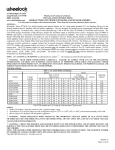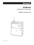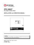
1
FireForce 8
NOTIFICATION APPLIANCE CIRCUIT EXPANDER
INSTALLATION & OPERATION MANUAL
P/N 52257:B • ECN 06-683 • 09/27/2006
Fire Alarm System Limitations
While a fire alarm system may lower insurance rates, it is not a substitute for fire insurance!
An automatic fire alarm system—typically made up of
smoke detectors, heat detectors, manual pull stations, audible
warning devices, and a fire alarm control panel with remote
notification capability—can provide early warning of a developing fire. Such a system, however, does not assure protection
against property damage or loss of life resulting from a fire.
The Manufacturer recommends that smoke and/or heat detectors be located throughout a protected premise following the
recommendations of the National Fire Protection Association
Standard 72 (NFPA 72), manufacturer's recommendations,
State and local codes, and the recommendations contained in
the Guides for Proper Use of System Smoke Detectors, which
are made available at no charge to all installing dealers.
These documents can be found at http://www.systemsensor.com/html/applicat.html. A study by the Federal Emergency Management Agency (an agency of the United States
government) indicated that smoke detectors may not go off in
as many as 35% of all fires. While fire alarm systems are
designed to provide early warning against fire, they do not
guarantee warning or protection against fire. A fire alarm system may not provide timely or adequate warning, or simply
may not function, for a variety of reasons:
Smoke detectors may not sense fire where smoke cannot
reach the detectors such as in chimneys, in or behind walls, on
roofs, or on the other side of closed doors. Smoke detectors
also may not sense a fire on another level or floor of a building.
A second-floor detector, for example, may not sense a firstfloor or basement fire.
Particles of combustion or “smoke” from a developing fire
may not reach the sensing chambers of smoke detectors
because:
•
Barriers such as closed or partially closed doors, walls, or
chimneys may inhibit particle or smoke flow.
•
Smoke particles may become “cold,” stratify, and not reach
the ceiling or upper walls where detectors are located.
•
Smoke particles may be blown away from detectors by air
outlets.
•
Smoke particles may be drawn into air returns before
reaching the detector.
The amount of “smoke” present may be insufficient to alarm
smoke detectors. Smoke detectors are designed to alarm at
various levels of smoke density. If such density levels are not
created by a developing fire at the location of detectors, the
detectors will not go into alarm.
Smoke detectors, even when working properly, have sensing
limitations. Detectors that have photoelectronic sensing
chambers tend to detect smoldering fires better than flaming
fires, which have little visible smoke. Detectors that have ionizing-type sensing chambers tend to detect fast-flaming fires
better than smoldering fires. Because fires develop in different
ways and are often unpredictable in their growth, neither type
of detector is necessarily best and a given type of detector
may not provide adequate warning of a fire.
Smoke detectors cannot be expected to provide adequate
warning of fires caused by arson, children playing with
matches (especially in bedrooms), smoking in bed, and violent
explosions (caused by escaping gas, improper storage of
flammable materials, etc.).
2
Heat detectors do not sense particles of combustion and
alarm only when heat on their sensors increases at a predetermined rate or reaches a predetermined level. Rate-of-rise
heat detectors may be subject to reduced sensitivity over time.
For this reason, the rate-of-rise feature of each detector
should be tested at least once per year by a qualified fire protection specialist. Heat detectors are designed to protect
property, not life.
IMPORTANT! Smoke detectors must be installed in the
same room as the control panel and in rooms used by the system for the connection of alarm transmission wiring, communications, signaling, and/or power. If detectors are not so
located, a developing fire may damage the alarm system, crippling its ability to report a fire.
Audible warning devices such as bells may not alert people
if these devices are located on the other side of closed or
partly open doors or are located on another floor of a building.
Any warning device may fail to alert people with a disability or
those who have recently consumed drugs, alcohol or medication. Please note that:
•
Strobes can, under certain circumstances, cause seizures
in people with conditions such as epilepsy.
•
Studies have shown that certain people, even when they
hear a fire alarm signal, do not respond or comprehend the
meaning of the signal. It is the property owner's responsibility to conduct fire drills and other training exercise to
make people aware of fire alarm signals and instruct them
on the proper reaction to alarm signals.
•
In rare instances, the sounding of a warning device can
cause temporary or permanent hearing loss.
A fire alarm system will not operate without any electrical
power. If AC power fails, the system will operate from standby
batteries only for a specified time and only if the batteries have
been properly maintained and replaced regularly.
Equipment used in the system may not be technically compatible with the control panel. It is essential to use only equipment listed for service with your control panel.
Telephone lines needed to transmit alarm signals from a
premise to a central monitoring station may be out of service
or temporarily disabled. For added protection against telephone line failure, backup radio transmission systems are recommended.
The most common cause of fire alarm malfunction is inadequate maintenance. To keep the entire fire alarm system in
excellent working order, ongoing maintenance is required per
the manufacturer's recommendations, and UL and NFPA standards. At a minimum, the requirements of NFPA 72 shall be
followed. Environments with large amounts of dust, dirt or
high air velocity require more frequent maintenance. A maintenance agreement should be arranged through the local manufacturer's representative. Maintenance should be scheduled
monthly or as required by National and/or local fire codes and
should be performed by authorized professional fire alarm
installers only. Adequate written records of all inspections
should be kept.
Limit-C1-2-2007
FireForce 8 Installation & Operation Manual P/N 52257:B 09/27/2006
Installation Precautions
Adherence to the following will aid in problem-free installation with long-term reliability:
WARNING - Several different sources of power can be
connected to the fire alarm control panel. Disconnect all
sources of power before servicing. Control unit and associated equipment may be damaged by removing and/or inserting cards, modules, or interconnecting cables while the unit is
energized. Do not attempt to install, service, or operate this
unit until manuals are read and understood.
CAUTION - System Re-acceptance Test after Software
Changes: To ensure proper system operation, this product
must be tested in accordance with NFPA 72 after any programming operation or change in site-specific software. Reacceptance testing is required after any change, addition or
deletion of system components, or after any modification,
repair or adjustment to system hardware or wiring. All components, circuits, system operations, or software functions known
to be affected by a change must be 100% tested. In addition,
to ensure that other operations are not inadvertently affected,
at least 10% of initiating devices that are not directly affected
by the change, up to a maximum of 50 devices, must also be
tested and proper system operation verified.
This system meets NFPA requirements for operation at 0-49º
C/32-120º F and at a relative humidity 93% ± 2% RH (noncondensing) at 32°C ± 2°C (90°F ± 3°F). However, the useful
life of the system's standby batteries and the electronic components may be adversely affected by extreme temperature
ranges and humidity. Therefore, it is recommended that this
system and its peripherals be installed in an environment with
a normal room temperature of 15-27º C/60-80º F.
Verify that wire sizes are adequate for all initiating and indicating device loops. Most devices cannot tolerate more than a
10% I.R. drop from the specified device voltage.
Like all solid state electronic devices, this system may
operate erratically or can be damaged when subjected to lightning induced transients. Although no system is completely
immune from lightning transients and interference, proper
grounding will reduce susceptibility. Overhead or outside aerial
wiring is not recommended, due to an increased susceptibility
to nearby lightning strikes. Consult with the Technical Services Department if any problems are anticipated or encountered.
Disconnect AC power and batteries prior to removing or
inserting circuit boards. Failure to do so can damage circuits.
Remove all electronic assemblies prior to any drilling, filing,
reaming, or punching of the enclosure. When possible, make
all cable entries from the sides or rear. Before making modifications, verify that they will not interfere with battery, transformer, or printed circuit board location.
Do not tighten screw terminals more than 9 in-lbs. Overtightening may damage threads, resulting in reduced terminal
contact pressure and difficulty with screw terminal removal.
This system contains static-sensitive components.
Always ground yourself with a proper wrist strap before handling any circuits so that static charges are removed from the
body. Use static suppressive packaging to protect electronic
assemblies removed from the unit.
Follow the instructions in the installation, operating, and programming manuals. These instructions must be followed to
avoid damage to the control panel and associated equipment.
FACP operation and reliability depend upon proper installation.
Precau-D1-9-2005
FCC Warning
WARNING: This equipment generates, uses, and can
radiate radio frequency energy and if not installed and
used in accordance with the instruction manual may
cause interference to radio communications. It has been
tested and found to comply with the limits for class A
computing devices pursuant to Subpart B of Part 15 of
FCC Rules, which is designed to provide reasonable
protection against such interference when devices are
operated in a commercial environment. Operation of this
equipment in a residential area is likely to cause interference, in which case the user will be required to correct
the interference at his or her own expense.
Canadian Requirements
This digital apparatus does not exceed the Class A limits
for radiation noise emissions from digital apparatus set
out in the Radio Interference Regulations of the Canadian Department of Communications.
Le present appareil numerique n'emet pas de bruits radioelectriques depassant les limites applicables aux appareils numeriques de la classe A prescrites dans le
Reglement sur le brouillage radioelectrique edicte par le
ministere des Communications du Canada.
Acclimate Plus™, HARSH™, NIS™, Notifier Integrated Systems™, NOTI•FIRE•NET™, and ONYXWorks™ are all trademarks; and FlashScan®, NION®,
NOTIFIER®, ONYX®, UniNet®, VeriFire®, and VIEW® are all registered trademarks of Honeywell International Inc. Echelon® is a registered trademark and
LonWorks™ is a trademark of Echelon Corporation. ARCNET® is a registered trademark of Datapoint Corporation. Microsoft® and Windows® are
registered trademarks of the Microsoft Corporation. LEXAN® is a registered trademark of GE Plastics, a subsidiary of General Electric Company.
©2006 by Honeywell International Inc. All rights reserved. Unauthorized use of this document is strictly prohibited.
FireForce 8 Installation & Operation Manual P/N 52257:B 09/27/2006
3
Documentation Feedback
Your feedback helps us keep our documentation up-to-date and accurate. If you have any comments
or suggestions about our online Help or printed manuals, you can email us.
Please include the following information:
•
•
•
•
•
•
Product name and version number (if applicable)
Printed manual or online Help
Topic Title (for online Help)
Page number (for printed manual)
Brief description of content you think should be improved or corrected
Your suggestion for how to correct/improve documentation
Send email messages to:
[email protected]
Please note this email address is for documentation feedback only. If you have any technical issues,
please contact Technical Services.
4
FireForce 8 Installation & Operation Manual P/N 52257:B 09/27/2006
Table of Contents
Section 1 Introduction ............................................................................................................ 7
1.1: General Description .......................................................................................................................................7
1.2: Functional Description...................................................................................................................................7
1.2.1: Normal Quiescent Operation ...............................................................................................................7
1.2.2: Alarm Condition ..................................................................................................................................7
1.2.3: Reset ....................................................................................................................................................7
1.2.4: Trouble Condition ...............................................................................................................................8
1.2.5: Normal AC Power Failure...................................................................................................................8
1.2.6: Delayed AC Power Failure..................................................................................................................8
1.2.7: Battery Operation ................................................................................................................................8
1.3: Electrical Operating Characteristics ..............................................................................................................9
Section 2 Installation ............................................................................................................ 11
2.1: Mounting Instructions..................................................................................................................................11
2.2: Electrical Connections .................................................................................................................................11
2.3: Function of Input/Output Connections ........................................................................................................11
2.3.1: AC Connections.................................................................................................................................11
2.3.2: Battery Connections ..........................................................................................................................11
2.3.3: 24 VDC Out Terminals (Power Limited) ..........................................................................................11
2.3.4: Earth Ground .....................................................................................................................................12
2.3.5: Trouble Relay ....................................................................................................................................12
2.3.6: Power Fail..........................................................................................................................................12
2.3.7: Extender Output Circuit Wiring (Power Limited).............................................................................12
2.3.8: Reference EOL Resistor (Power Limited).........................................................................................13
2.3.9: Input signal wiring (Power Limited) .................................................................................................13
Section 3 Function of Switches, LEDs and Jumpers ......................................................... 15
3.1: Programming Switches ..............................................................................................................................15
3.2: Function of LED Indicators ........................................................................................................................16
3.3: Jumper Functions.........................................................................................................................................16
3.3.1: Jumper J1 ..........................................................................................................................................16
3.3.2: Jumper J2 ..........................................................................................................................................16
3.4: Optional Class A Adapter ............................................................................................................................16
Section 4 Operation ............................................................................................................... 17
4.1: Start-up Procedure .......................................................................................................................................17
4.2: Operating Instructions .................................................................................................................................17
4.2.1: Alarm Condition ................................................................................................................................17
4.2.2: Trouble Condition .............................................................................................................................17
4.2.3: Testing and Maintenance...................................................................................................................17
4.3: Battery Applications ....................................................................................................................................17
4.3.1: Battery Capacity ................................................................................................................................17
Appendix A: Compatible Devices ........................................................................................ 19
A.1: Compatible Notification Devices ..............................................................................................................19
A.2: Synchronized Horns and Strobes ................................................................................................................20
Appendix B: FireForce 8 Battery Calculation Chart .......................................................... 21
Appendix C: Wiring Drawings ............................................................................................. 23
C.1: B-W479 Wiring Diagram: Notification Circuit Expander ........................................................................23
C.2: B-W479-1 Wiring Diagram: Synchronized Horn & Strobe .......................................................................24
C.3: C-M822, Assembly Drawing, FireForce 8 Cabinet ....................................................................................25
FireForce 8 Installation & Operation Manual P/N 52257:B 09/27/2006
5
Table of Contents
6
FireForce 8 Installation & Operation Manual P/N 52257:B 09/27/2006
Section 1: Introduction
1.1 General Description
The FIREFORCE 8 is a notification appliance circuit extender panel designed to extend the power
capabilities of the existing notification appliance circuits and provide power for other ancillary
devices.
An FIREFORCE 8 panel consists of two notification appliance circuit inputs and four class B, style
Y, two class A, style Z, or two class B and one class A notification appliance circuits. Two class B
(1 class A) circuits will always be controlled by the first input, the other two class B (1 class A)
circuits may be operated from either input. Each of these output circuits is capable of providing 3.0
amps of power limited notification appliance power and are supplied from an 8 Amp, 24 VDC
power supply. Using the optional Class A Adapter, PN 31076, four class A outputs at 2.5A each
may be obtained. Outputs may follow the inputs, or be programmed to provide temporal outputs for
a steady input They can also be programmed to provide strobe and horn synchronizing signals
when none are on the input. The internal sync. signals can permit horns and strobes to be connected
to a single wire pair on each output, controlled by the two inputs, or they can be separated and
operated on individual outputs. All inputs and outputs are supervised for open or shorted
conditions. EOL resistor values can be changed by connecting a sample EOL resistor to the unit.
This allows compatibility with existing NAC circuits. An internal battery charger is also provided
with the FIREFORCE 8 to provide standby battery operation. The panel is mounted in a rigid sheet
metal enclosure with the dimensions of (12 5/8"W x 18"H x 4 1/2"D).
1.2 Functional Description
1.2.1 Normal Quiescent Operation
In the normal quiescent condition the green Power On LED is illuminated indicating AC line
operation. The yellow TRBL LEDs are off indicating that all supervision circuits are normal.
1.2.2 Alarm Condition
Whenever an alarm condition occurs at the Main FACP the resultant 24V output from its indicating
circuit will energize the connected polarity sensing inputs. This input will then activate the
notification appliance output circuits on the FIREFORCE 8 according to how they are
programmed. Input 1 will always control Outputs 1 and 2. Input 2 normally controls Outputs 3, and
4 (Default) however this pair of outputs can be programmed to operate from Input 1. The
FIREFORCE 8 notification appliance circuits will follow steady, march time, temporal or coded
signals from the main control panel, and will pass on strobe and horn synchronization signals if
they are present on the input.
When the unit is programmed to generate synchronization signals, combined horn and strobe
synchronization signals are placed on each selected output pair and turned on and off by the inputs
in the manner described as default above.
NOTE: When the unit is programmed to generate synchronization signals and have all four outputs
controlled by input 1, the strobe synchronization signals are placed on all four outputs when input 1 is
active. When input 1 and 2 are active, the horn synchronization signals are combined with the strobe
synchronization signals on all four outputs. In this manner, horns and strobes can be connected to
same pair of wires on any output, and be controlled separately.
FireForce 8 Installation & Operation Manual P/N 52257:B 09/27/2006
7
Introduction
Functional Description
1.2.3 Reset
The FIREFORCE 8 will return to the quiescent condition automatically upon restoration of the
Main FACP to normal operation
1.2.4 Trouble Condition
A trouble condition is indicated by a TRBL LED illuminating and the common Form “C”
TROUBLE FAIL relay contacts transferring. The trouble signal will be transmitted to the Main
FACPs by opening the Indicating Circuits that are used to control the FIREFORCE 8. An alarm
from the main control panel will override a trouble condition.
The FIREFORCE 8 monitors its output notification appliance circuits for an open or shorted
condition. Notification appliance circuits with a short circuit trouble can not be activated.
A trouble is indicated by any one of the following conditions:
Indicator
Name
Trouble Condition
LED 8
PWR ON
A brown-out or black-out AC line condition
LED 7
AUX TRBL
A low or missing output, or a short circuit on the AUXilliary
output
LED 6
BATT TRBL
A low or missing battery
LED 5
GF TRBL
An earth fault on external wiring
LED 4, 3, 2, 1
SIG(4,3,2,1) TRBL
A short circuit or an open on a supervised notification appliance
circuit
1.2.5 Normal AC Power Failure
When the AC fails or falls below 100VAC at the 120VAC setting or 190VAC at the 240VAC
setting, the FIREFORCE 8 will go into the Trouble condition. It will switch to Battery Operation,
deactivate the Trouble and Power Fail relays, extinguish the AC On LED (LED 8), and transmit the
trouble over the input Signal Circuits.
1.2.6 Delayed AC Power Failure
When S7 AC 6HR is set (Dialer Operation) An AC failure will be handled in the same manner as
above EXCEPT the TROUBLE relay will not transfer, and the failure notification will not be
transmitted over the input Signal Circuits until the failure has existed for 6 hours. The POWER
FAIL relay will transfer in order to provide an external trouble indication.
1.2.7 Battery Operation
Indicated by the extinguishing of the green Power On LED.
Standby operation occurs whenever the main power source fails or falls below 100VAC @ 120VAC
setting or 190VAC @ 240VAC setting. In this situation the FIREFORCE 8 will automatically
transfer system operation to the standby battery set without the loss of any alarm condition present
prior to the transfer. The FIREFORCE 8 panel will transfer back to the main power source when
the operating voltage returns to 105VAC @ 120VAC setting or 194VAC @ 240VAC setting.
Should the battery become disconnected, have a blown fuse, or develop low voltage, the
FIREFORCE 8 will indicate a Battery fault and light LED 2. Replace batteries when required.
8
FireForce 8 Installation & Operation Manual P/N 52257:B 09/27/2006
Electrical Operating Characteristics
Introduction
1.3 Electrical Operating Characteristics
Input Voltage
120 VAC @ 3.3 Amps or 240 VAC @ 2 Amps (Jumper selected)50/60 Hz.
Input Control Signal
10VDC to 30VDC, or 12V to 28V Full Wave Rectified, Polarity Reversing.
Output Voltage
24 Volt DC @ 8Amps
NAC outputs 1- 4
3.0 Amps Maximum per output.
NAC outputs 1- 4
With optional Class A adapter
2.5 Amps Maximum per output.
AUX Power
0.15 Amps under all conditions. 2.0 Amps if load is removed during
operation from battery.
Total System Current
Total loading on all outputs shall not exceed 8 Amps.
FireForce 8 Installation & Operation Manual P/N 52257:B 09/27/2006
9
Introduction
10
Electrical Operating Characteristics
FireForce 8 Installation & Operation Manual P/N 52257:B 09/27/2006
Section 2: Installation
2.1 Mounting Instructions
The standard mounting is a surface mount cabinet. The unit must be securely attached to a
permanent partition using suitable fasteners. Four mounting holes are provided to accept 1/4-inch
dia. screws max. There are nine combination knockouts provided, located three on the top and
three on each side of the cabinet. Knockouts can accept 1/2, or 3/4 inch conduit.
2.2 Electrical Connections
For field wiring connections, refer to Inter-equipment Wiring DWG. No. B-W479 in Appendix C.1.
2.3 Function of Input/Output Connections
2.3.1 AC Connections
120VAC or 240VAC connects to the AC Terminal Block on the Power Supply
Connections for the A.C. Mains
J1 Terminal
L1 (Hot)
!
GND
L2 (Neutral)
WARNING: When installing to operate from 240VAC, it is necessary to remove the jumper E1 - E2
on the power supply printed circuit board. Failure to do so will result in damage to the power
supply when AC voltage is applied.
2.3.2 Battery Connections
Batteries connect to the BATT+, BATT- terminals. Sealed Lead Acid Batteries are required to
provide 24 Volts DC @ 8 Amps max. The maximum battery size allowable is 26AH. Larger battery
packs with there own enclosures and chargers can be accommodated by removing the jumper on J1,
which disables the internal battery charger. Connect ONLY using a 15A fuse.
Connections for the Battery
TB1 TERMINALS
BATT+
BATT-
2.3.3 24 VDC Out Terminals (Power Limited)
Auxiliary Power Output @ 24 Volts DC, 150 mA, (2.0 Amps maximum if an external disconnect is
used during periods of power failure). Two terminals are provided (+, -). Power limited output of
2.0 amps. (Deduct the current used from the 8 Amps total system load).
Connections for the
Auxiliary 24VDC
TB4 TERMINALS
A+
FireForce 8 Installation & Operation Manual P/N 52257:B 09/27/2006
A-
11
Installation
Function of Input/Output Connections
2.3.4 Earth Ground
Connect to Earth Ground on the Power Supply module.
Earth Ground Connections
J1 Terminals
GND
2.3.5 Trouble Relay
The common trouble relay is a normally energized Form C relay that transfers when the
FIREFORCE 8 detects a trouble condition. The contacts are rated for 2 amps @ 30VDC with a
power factor of 0.6 or higher.
Trouble Fail
TB2 Terminals
NC
Comm
NO
2.3.6 Power Fail
The Power Fail relay is a normally energized Form C relay that transfers when a power failure or
brown out condition exists. The contacts are rated for 2 amps @ 30VDC with a power factor of 0.6
or higher.
Power Fail
TB2 Terminals
NC
Comm
NO
2.3.7 Extender Output Circuit Wiring (Power Limited)
The FIREFORCE 8 Notification Appliance Circuit outputs can provide up to 3.0 Amps (power
limited) of 24 VDC each (total panel output is limited to 8 Amps). The outputs can be arranged as 4
Style Y (Class B), 2 Style Z (Class A) or 1 Style Z and 2 Style Y circuits. The EOL resistor value
for Style Y wiring is 3.9K ohms unless a reference resistor of a different value is used. Terminals
(n) L1 and (n) L2 are connections for style Y (Class B) wiring These designations are preceded by
the circuit number (n). When Style Z (Class A) wiring is used, terminal 1L1 will return to terminal
2L1 and terminal 1L2 will return to terminal 2L2, likewise, terminal 3L1 will return to terminal
4L1 and terminal 3L2 will return to terminal 4L2 for the second Class A circuit. Terminal L1
switches negative and terminal L2 switches positive during alarm condition. Either pair of
circuits can be designated Class A or Class B independently of the other pair.
Circuit
Style Z - Class A
Notification Appliance Circuit Connections
Terminals
12
Style Y - Class B
Notification Appliance
Circuit Connections
Terminals
1L1
2L1
1L2
2L2
1
1L1
2L2
-
-
-
-
2
2L1
2L2
3L1
4L1
3L2
4L2
3
3L1
3L2
-
-
-
-
4
4L1
4L2
FireForce 8 Installation & Operation Manual P/N 52257:B 09/27/2006
Function of Input/Output Connections
Installation
2.3.8 Reference EOL Resistor (Power Limited)
To accommodate existing Notification Appliance circuits that have EOL resistors of various values,
provisions are made to attach a reference EOL resistor, matching the existing EOL, within the
range of 2.0K to 25.0K ohms. Normally, a 3.9K resistor should be attached to the Ref.
Terminals. All Style Y (Class B) outputs must have EOL resistors of the same value as the
reference resistor. EOL values outside of the 2.0K – 25.0 K range will cause all of the Style Y NAC
output Trouble LEDs to light steady.
Ref
TB3 Terminals
REF+
REF-
2.3.9 Input signal wiring (Power Limited)
The main FACP notification appliance circuit inputs are +IN, -IN. When polarity is reversed on the
main FACP notification appliance circuit, the output circuits on the FIREFORCE 8 will activate
according to their programming. These inputs restore when the Main FACP circuit is restored. +IN
and -IN are internally connected to +OUT and -OUT for connection to devices beyond the
FIREFORCE 8. Should a trouble condition occur, the circuit is opened. If an alarm is received
during trouble the circuit is restored to allow devices beyond the FIREFORCE 8 to be operated.
Signal 1 always activates output Signal Circuits 1 and 2., and depending on the position of switch
SW1-8 can also control output Signal Circuits 3 and 4. Otherwise, Signal 2 controls output Signal
Circuits 3 and 4.
NOTE: When the Strobe Sync. Added mode is selected, and Ckts. 3 and 4 are controlled by Input
1, and a single input is to control both the Horns and the Strobes, The Output of Input 1 should be
connected to the Input of Input 2, and the signal Ckt. continuation or EOL resistor should be
connected to the output of Input 2.
Signal 1
Terminals
1+IN
1-IN
1+OUT
1-OUT
Signal 2
Terminals
2+IN
2-IN
2+OUT
2-OUT
FireForce 8 Installation & Operation Manual P/N 52257:B 09/27/2006
13
Installation
14
Function of Input/Output Connections
FireForce 8 Installation & Operation Manual P/N 52257:B 09/27/2006
Section 3: Function of Switches, LEDs and Jumpers
3.1 Programming Switches
Outputs 1 & 2
SW-1.1
SW-1.2
Function
SIG1/2A
SIG1/2B
Open
Open
Output follows the Input (Also passes Sync. signals) Should NOT
be used for Full Wave Rectified inputs
Closed
Open
Steady Input, Temporal Output
Open
Closed
Steady Input, Steady Output, Strobe Sync. added
Closed
Closed
Steady input, steady output, noise eliminated.
(Does NOT pass Sync. signals)
Outputs 3 & 4
SW-1.3
SW-1.4
Function
SIG3/4A
SIG3/4
Open
Open
Output follows the Input (Also passes Sync. signals) Should NOT
be used for Full Wave Rectified inputs
Closed
Open
Steady Input, Temporal Output
Open
Closed
Steady Input, Steady Output, Strobe Sync. added
Closed
Closed
Steady input, steady output, noise eliminated.
(Does NOT pass Sync. signals)
Sync. Codes
( Used ONLY if synchronizes. Added option is selected with switch 1-1 through 4)
SW-1.5
SW-1.6
Function
SYN/SEL A
SYN/SEL B
Open
Open
Gamewell Sync and Wheelock Sync
Closed
Open
System Sensor Sync
Open
Closed
Faraday Sync and Amseco Sync
Closed
Closed
Gentex Sync
Power Fail Reporting
SW-1.7
Function
AC 6HR
Open
TROUBLE FAIL reported immediately on power failure
Closed
TROUBLE FAIL delayed for 6 hours on power failure
Input Select
SW-1.8
Function
SIG SEL
Closed
Outputs 3 / 4 controlled by Input 2
Open
Outputs 3 / 4 controlled by Input 1, also in Strobe Sync. Added mode, Input 1 controls
strobe synch. signals and, Input 2 controls the horn synch. signals, both of which can
be combined on all 4 outputs.
FireForce 8 Installation & Operation Manual P/N 52257:B 09/27/2006
15
Function of Switches, LEDs and Jumpers
Function of LED Indicators
3.2 Function of LED Indicators
INDICATOR
LED#
Color
Description
PWR ON
LED # 8
Green
Indicates AC line operation.
AUX TRBL
LED # 7
Yellow
Indicates a short or overload on the Aux.
Output.
BATT TRBL
LED # 6
Yellow
Indicates a low battery voltage or missing
battery.
GF TRBL
LED # 5
Yellow
Indicates an external wiring connection is not
adequately isolated from the earth ground.
NAC #4
LED # 4
Yellow
Indicates a short or open circuit in the external
wiring.
NAC #3
LED # 3
Yellow
Indicates a short or open circuit in the external
wiring.
NAC #2
LED # 2
Yellow
Indicates a short or open circuit in the external
wiring.
NAC #1
LED # 1
Yellow
Indicates a short or open circuit in the external
wiring.
3.3 Jumper Functions
3.3.1 Jumper J1
When the jumper on J1 is in place, the internal Battery Charger is enabled. To disable the charger
and allow an external charger to maintain the batteries, remove this jumper.
3.3.2 Jumper J2
When the jumper on J2 is in place, the FF 8 performs its own ground fault tests. When the power
supply common is connected to the power supply common of another device, such as when a
common battery is used for a FACP and the FF8, remove this jumper.
3.4 Optional Class A Adapter
The optional Class A Adapter allows the connection of four class A NAC circuits to the FireForce
8. This is a passive device that uses no power from the FF8. Install the adapter as described in
Drawing A-M1192, and attach the field wiring according to Drawing B-W479-4 in Appendix C.1.
16
FireForce 8 Installation & Operation Manual P/N 52257:B 09/27/2006
Section 4: Operation
4.1 Start-up Procedure
Connect A.C. first, then connect batteries
4.2 Operating Instructions
4.2.1 Alarm Condition
Alarm devices operate in unison with the Main FACP alarm devices. The alarm-activated outputs
are reset through operation of the Reset switch on the Main FACP.
4.2.2 Trouble Condition
The associated trouble LED (yellow) will illuminate.
4.2.3 Testing and Maintenance
System Testing should be performed periodically to insure proper operation.
1.
Test the indicating circuits by initiating an alarm or test at the Main FACP.
2.
Test for proper operation by actuating the notification appliance circuit the FIREFORCE 8 is
monitoring.
3.
Standby batteries and AC transfer are tested by interrupting the AC power line while an alarm
test condition exists (see 1 above).
4.3 Battery Applications
4.3.1 Battery Capacity
Battery Capacity is 26 ampere-hours maximum for the FIREFORCE 8 using the internal battery
charger. The max. charging rate is 0.75 amps. Larger capacity batteries can be used with the
FireForce 8 if they are housed in an external UL listed enclosure, and use an external UL listed
battery charger with sufficient capacity to restore the full charge to the batteries in the required
time. To use an external battery charger, remove the jumper at J1. The alternate enclosure and
battery charger shall be Listed for Fire Protective Signaling use.
FireForce 8 Installation & Operation Manual P/N 52257:B 09/27/2006
17
Operation
18
Battery Applications
FireForce 8 Installation & Operation Manual P/N 52257:B 09/27/2006
Appendix A: Compatible Devices
A.1 Compatible Notification Devices
Part #
Catalog #
Part #
Catalog #
Part #
Catalog #
70871
MIZ-24-R
71562
SR-24110-HFR
71717
RSSP-24110W-FR
70873
MIZ-24-W
71569
RSP-241575-VFR
71727
AS-2415C-FW
71138
MT-12/24-R
71573
AMT-12/24-R
71728
AS-2430C-FW
71140
MT-24-WM-VFR
71574
AMT-24-LS-VFR
71729
AS-2475C-FW
71287
MIZ-24-LS-VFR
71575
AMT-24-IS-VFR
71730
RSS-2415C-FW
71288
MIZ-24-LSM-VFR
71576
AMT-24-LSM-VFR
71731
RSS-2430C-FW
71289
MIZ-24-MS-VFR
71614
MT4-12/24-R
71732
RSS-2475C-FW
71290
MIZ-24-IS-VFR
71616
SR-2475-VFR
71733
RSSP-2415W-FR
71292
MT-24 -LS-VFR
71679
AS-2415W-FR
71736
ET70-2415W-FR
71293
MT-24-LSM-VFR
71680
AS-241575W-FR
71737
ET70-241575W-FR
71294
MT-24-MS-VFR
71681
AS-2430W-FR
71738
ET70-2430W-FR
71295
MT-24-IS-VFR
71682
AS-2475W-FR
71739
ET70-2475W-FR
71426
MT-24 -SL-VFR
71683
AS-24110W-FR
71740
ET90-2415C-FW
71427
MT-24-SLM-VFR
71684
AS-24100C-FW
71741
ET90-2430C-FW
71543
AS-2415-VFR
71685
NH-12/24-R
71742
ET90-2475C-FW
71544
AS-241575-VFR
71686
NS-2415W-FR
71743
ET90-24100C-FW
71545
AS-2430-VFR
71687
NS-241575W-FR
71744
E70-2415W-FR
71546
AS-2475-VFR
71688
NS-2430W-FR
71745
E70-241575W-FR
71547
AS-24110-HFR
71689
NS-2475W-FR
71746
E70-2430W-FR
71548
SM-12/24-R
71690
NS-24110W-FR
71747
E70-2475W-FR
71549
DSM-12/24-R
71691
RSS-2415W-FR
71748
E70-24110W-FR
71550
RS-2415-VFR
71692
RSS-241575W-FR
71749
E90-2415C-FW
71551
SR-2415-VFR
71693
RSSP-241575W-FR
71750
E90-2430C-FW
71552
SRP-2415-VFR
71694
RSSP-2430W-FR
71751
E90-2475C-FW
71553
RS-241575-VFR
71695
RSS-2430W-FR
71752
E90-24100C-FW
71554
SRP-241575-VFR
71696
RSSP-2475W-FR
71758
CH90-24-W
71555
SR-241575-VFR
71697
RSS-2475W-FR
71759
CH70-24-R
71556
RS-2430-VFR
71698
RSS-24110W-FR
71760
CH70-2415W-FR
71557
RSP-2430-VFR
71699
RSS-24100C-FW
71761
CH70-241575W-FR
71558
RSP-2475-VFR
71711
AH-24WP-R
71762
CH70-2430W-FR
71559
RS-2475-VFR
71712
RS-2415W-FR
71763
CH70-2475W-FR
71560
RS-24110-HFR
71713
RS-241575W-FR
71764
CH70-24110W-FR
71561
SRP-24110-HFR
71714
W3MT-24-VFR
FireForce 8 Installation & Operation Manual P/N 52257:B 09/27/2006
19
Compatible Devices
Synchronized Horns and Strobes
A.2 Synchronized Horns and Strobes
System Sensor
SC2415_
Faraday
Wheelock
Gamewell
Amseco
GEC Series
AS-24MCW
72032
SHW24-153075
SC241575_
GES Series
RSS-24MCW
72033
SLW24-153075
SC2430_
GEH Series
72035
SHW24W-75110
72036
SLW24W-75110
SC2475_
2700 Sync Series
Gentex
(Max 25 per ckt)
SC2495_
HW-24A
SC24115_
HW-24
SC24177_
PC2415_
PC241575_
PC2430_
PC2475_
PC2495_
PC24115_
PC24177_
20
FireForce 8 Installation & Operation Manual P/N 52257:B 09/27/2006
Appendix B: FireForce 8 Battery Calculation Chart
Circuit
Normal Current
Notification Appliance Ckt. 1
Alarm Current
Cl A, .050A + Device Load 1 or
Cl B, .065A + Device Load 1 & 2
Or
Class A Adapter,
.065A + Device Load 1 & 2
Notification Appliance Ckt. 2
Notification Appliance Ckt. 3
Cl A, .050A + Device Load 3 or
Cl B, .065A + Device Load 3 & 4
Or
Class A Adapter,
.065A + Device Load 3 & 4
Notification Appliance Ckt. 4
External Load A+, A+/- 24 VDC
Common Control
.030 A
Normal Current
(Total of Center Column)
Alarm Current
(Total of Right Column)
Hours of
Standby
.055 A
Total Normal
Current
X
=NORMAL Amp Hours
Total Alarm
Current
Hours of
Alarm
X
=ALARM Amp Hours
TOTAL Amp Hours
Safety Factor
X 1.25
BATTERY AH REQUIRED
26 AH Max
NOTE:
1.
Normal current times total number of standby hours = Total Normal Amp Hours
2.
Alarm current times total number hours of alarm = Total Alarm Amp Hours
3.
Total normal Amp Hours + Total alarm Amp Hours + 25% = Minimum Battery Size
4.
Total Load of Notification Appliance Ckt. And External Load Not To Exceed 8 Amps.
FireForce 8 Installation & Operation Manual P/N 52257:B 09/27/2006
21
FireForce 8 Battery Calculation Chart
22
FireForce 8 Installation & Operation Manual P/N 52257:B 09/27/2006
Appendix C: Wiring Drawings
C.1 B-W479 Wiring Diagram: Notification Circuit Expander
N/C COMM N/O
POWER FAIL
L1
GND
L2
B-W479rotatedgw.ai
N/C COMM N/O
TROUBLE FAIL
FireForce 8 Installation & Operation Manual P/N 52257:B 09/27/2006
23
Wiring Drawings
B-W479-1 Wiring Diagram: Synchronized Horn & Strobe
N/C COMM N/O
TROUBLE FAIL
24
N/C COMM N/O
POWER FAIL
N/C COMM N/O
TROUBLE FAIL
N/C COMM N/O
POWER FAIL
B-W479-1rotatedgw.ai
C.2 B-W479-1 Wiring Diagram: Synchronized Horn & Strobe
FireForce 8 Installation & Operation Manual P/N 52257:B 09/27/2006
C-M822, Assembly Drawing, FireForce 8 Cabinet
Wiring Drawings
C.3 C-M822, Assembly Drawing, FireForce 8 Cabinet
REF+ REF-
+IN
SIGNAL 1
-IN +OUT -OUT
+IN
SIGNAL 2
-IN +OUT -OUT
CABINET 31107
TB4
4L2
TB3
4L1
(4) SCREW 69412
SIG1/2A
SIG1/2B
SIG3/4A
SIG3/4B
SYN/SELA
SYN/SELB
AC 6HR
SIG SEL
3L2
3L1
2L2
SW1
FIREFORCE 8 MODULE
2L1
1L2
31053
1L1
AA+
(4) SPACER 68567
LED8
TB2
GRN
PWR
ON
LED7
YEL
AUX
TRBL
LED6
LED5
LED4
YEL
YEL
YEL
BATT
TRBL
GF
TRBL
SIG4
TRBL
LED3
YEL
LED2
YEL
LED1
YEL
SIG3
SIG2
SIG1
TRBL
TRBL
TRBL
TB1
LOCK
(4) SCREW 69412
69081
POWER SUPPLY 8 AMPS
31057
NAMEPLATE 72091 LOCATE ON
FRONT OF DOOR
WHT
RED
BLK
RED
BLK
2.00
BATTERY,
ORDER SEPARATELY)
(2 REQUIRED)
RED
C-M822gw.ai
BLK
CL
FireForce 8 Installation & Operation Manual P/N 52257:B 09/27/2006
25
Wiring Drawings
26
C-M822, Assembly Drawing, FireForce 8 Cabinet
FireForce 8 Installation & Operation Manual P/N 52257:B 09/27/2006
FireForce 8 Installation & Operation Manual P/N 52257:B 09/27/2006
27
Automation and Control Solutions
Honeywell Power Products
l2 Clintonville Road
Northford, CT 06472
www.honeywellpower.com
® U.S. Registered Trademark
© 2005 Honeywell International Inc.
52257 HonRev. Rev. 07-03