1
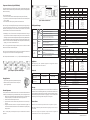
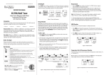
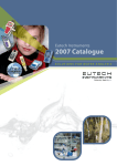
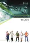
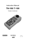
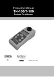
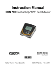
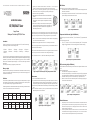
This Instruction Manual is also available for download on our Web-site: eutechinst.com or 4oakton.com
INSTRUCTION MANUAL
EC/TDS/SALT Testr
Large Screen
Waterproof Conductivity/TDS/Salt Tester
Note: At this point, the non-plus models will have its upper and lower display showing readings
with resolution of its plus version. Reading adjustment can then be made from its last significant
digit. Upon confirming the calibration, the reading changes back to its original resolution.
7. Wait for 5 seconds for the tester to automatically confirm the calibration value by displaying
“CO” and return to the measurement mode.
8. Replace the battery compartment lid. The tester is now ready for measurement.
Introduction
Thank you for selecting our microprocessor-based waterproof EC / TDS / SALT tester with large
dual line display. You have one of the following models:
• ECTestrlow
• TDSTestrlow
• SALTTestr
1. Organise your calibration standard solution in two beakers – one for rinsing and
the other for calibration. Prepare separate de-ionized water for electrode rinsing.
2. Twist off and open the battery compar tment lid (the cap with the lanyard loop).
You will see two switches – the INC (increment) and DEC (decrement) keys.
3. Switch on the unit using the ON/OFF key.
4. Rinse the electrode in de-ionized water and then rinse with the calibration
INC Key
standard.
+
5. Dip the electrode to the calibration standard intended for calibration
and swirl gently to create a homogenous sample. Wait for the reading
to stabilize.
6. Press the INC or DEC key to enter calibration mode and to adjust the
reading to the calibration standard value. The upper display will be the
adjustable reading for calibration whereas the lower display will be the
default reading of the standard.
• ECTestrlow+
• TDSTestrlow+
• ECTestrhigh
• TDSTestrhigh
• ECTestrhigh+
• TDSTestrhigh+
• ECTestrpure+
• TDSTestrpure+
The non plus models are designed with user-replaceable two-pin type sensor with many user friendly
features such as the Hold function, Automatic Temperature Compensation and Self-Diagnostic Messaging
capabilities. The plus models, with the user-replaceable cup type sensor, have more additional
features such as simultaneous temperature display, °C or °F selection, and have higher resolution
measurement.
This manual provides a step-by-step guide to operate the testers.
Note: To exit this program without confirming the calibration, press the HOLD button before the
automatic confirmation takes place.
The tester is factory calibrated. However, to ensure accuracy, you can calibrate the tester on a regular
basis. Depending on the model selected, you can calibrate the Conductivity / TDS / Salt / Temperature
on a one point calibration using the appropriate calibration standard.
The following table lists each model allowable calibration range when selecting a calibration standard.
It is best to select a standard close to the test solution value.
Model
E C TTee s t r l o w
E C TTee s t r l o w +
E C TTee s t r h i g h
E C TTee s t r h i g h +
E C TTee s t r p u r e +
Calibration
Standard Range
200 to 1990
uS/cm
200 to 1999
uS/cm
2.00 to 19.90
mS/cm
2.00 to 19.99
mS/cm
20.0 to 199.9
uS/cm
Calibration
Standard Range
INC
INC
DEC
DEC
After 5 sec,
“CO” is
displayed
signifying
automatic
confirmation
Figure 1: Example of a calibration sequence using 2764 µS calibration standard
1. Press the ON/OFF button to switch the tester on.
2. Dip the electrode into the test solution making sure that it is fully immersed. Stir to clear any
trapped air bubbles from the electrode and let the reading stabilize. For plus models, you
can opt for the cup style measurement by filling the electrode cup with sample of test solution.
3. Note the value or press HOLD button to freeze the reading. To release the reading, press HOLD
again.
4. Press ON/OFF to turn off tester. If you do not press a button for 8.5 minutes, the tester will
automatically shut off to conserve batteries.
200 to
1999 ppm
1.00 to
10.00 ppt
Table 1
1.00 to
10.00 ppt
20.0 to
199.9 ppm
1.00 to
10.00 ppt
This feature lets you select either the Celsius (°C) or the Fahrenheit (°F) temperature mode
display.
From the measurement mode,
1. Press °C/°F button to select the desired temperature mode. The temperature
display will toggle between the Celsius reading and the Fahrenheit reading.
TDS Factor Setting (Only for TDS Models)
The TDS models features includes the setting of the TDS factor. You can adjust the TDS factor from 0.4
to 1.0.
From the measurement mode,
1. Press HOLD button to bring the tester to the HOLD mode.
2. Press either the INC or DEC key to enter the TDS Factor Setting mode. The upper display will
be the adjustable TDS factor whereas the lower display will be the last TDS Factor setting.
3. Use the INC or DEC key to set the correct TDS factor for your sample measurement.
4. Wait for 5 seconds for the tester to automatically confirm the new setting by displaying “CO”
and return to the measurement mode.
INC
INC
DEC
DEC
After 5 sec,
“CO” is
displayed
signifying
automatic
confirmation
Figure 5: Example of setting the TDS Factor
Electrode Maintenance
TDST
estr lo
w TDST
estr lo
w+ TDST
estrhigh TDST
estrhigh+ TDST
estr pur
e+ S A LLTT e s t r
TDSTestr
low
TDSTestr
low+
TDSTestrhigh
TDSTestrhigh+
TDSTestr
pure+
200 to
1990 ppm
Temperature Mode Selection (Only for PLUS Models)
Figure 4: Example of a temperature mode selection
ON/OFF
Model
Figure 3: Example of HOLD Function
Note: The calibration window is +/- 50% from the default reading of the standard.
Measurement
Calibration
This feature lets you freeze the display for a delayed observation.
1. Press HOLD button to freeze the measurement. A ‘HOLD’ indicator will be displayed and the
measurement will be frozen.
2. Press HOLD again to release the measurement. The ‘HOLD’ indicator will not be displayed
anymore indicating the held measurement is released.
Note: The tester will exit calibration mode with “Er.0” message if the temperature is outside the
0 to 50°C range. Please refer to information under ’Self Diagnostic Messages’.
Before you begin:
Remove the electrode’s protective cap. Soak the electrode for a few minutes in alcohol to remove any
oil stains on the electrodes which will affect the accuracy of the tester. Rinse thoroughly with deionized water and shake off dry.
HOLD Function
Figure 2: Example of a Power Up Sequence
1. Always keep the sensor electrodes clean. Rinse the electrodes with de-ionized water and
wipe them dry with clean cloth before storing with its protective cap. For the plus models,
remove the white plastic cup insert to thoroughly clean viscous solutions. Never scratch
the electrodes with a hard substance.
2. For better performance, soak the electrode in alcohol for 10 to 15 minutes and rinse with
de-ionized water before starting any measurement process. This is to remove dirt and oil
stains on the electrode which may affect the accuracy of the measurements.
Temperature Calibration (Only for PLUS Models)
Roate collar
away from you
Temperature calibration need not be performed every time, unless the temperature reading differs
from that of an accurate thermometer. If temperature calibration is performed, Conductivity/TDS/Salt
calibration is mandatory.
Electrode Module
From the measurement mode,
1. Press the °C/°F button to select the desired temperature mode (Celsius or Fahrenheit).
2. Dip the tester into a solution of known temperature and allow time for the in built temperature
sensor to stabilize.
3. Press either the INC or DEC key to bring the tester to the calibration mode.
Note: At this stage, if the Conductivity/TDS/Salt reading is outside the specified range (showing Or
or Ur), the tester will show an error message of “Er.1”. You can still proceed with the temperature
calibration by continuing with step 4 or if the °C/°F button is not pressed within 2 seconds, the tester
will exit the calibration mode and return to the measurement mode.
4. Immediately press the °C/°F button to switch to the temperature calibration mode. The upper
display shows the current measured temperature reading based on the last set offset and the
lower display shows the current measured temperature reading based on factory default calibration.
5. Use the INC and DEC key to adjust the upper temperature reading to the known temperature value.
6. Wait for 5 seconds for the tester to automatically confirm the temperature calibration value by
displaying “CO” and return to the measurement mode.
Note: To exit this program without confirming the calibration, press the °C/°F button or the HOLD
button before the automatic confirmation takes place.
Note: The tester will exit calibration mode with “Er.0” message if the temperature is outside the 0 to
50°C range. Please refer to information under ’Self Diagnostic Messages’.
Large O-Ring
Insert Electrode Module
Ribbed collar
Small O-Ring
Small Tab
Large Tab
Figure 7: Removal of collar from tester
Self-Diagnostic Messages
3 Bars indicates Battery is full (100%)
2 Bars indicates 50% of the battery life is left
Low battery
indicator
1 Bar indicates 25% of the battery life is left
Blinking battery casing indicates the need to replace
batteries with fresh ones as specified by manufacturer
Over range /
Under range
signal
Or / Ur
(Still)
ATC / Or /
Ur (Blinking)
Error
Message
E rr.. 0
E rr.. 1
Notes: The temperature calibration window is +/- 5°C (+/- 9°F) from the default temperature reading.
The sensor electrodes have short circuited.
Replacement sensor is not connected properly to the
tester during sensor replacement
Measured value or temperature value (for plus models)
exceeds its specified maximum or minimum value
Blinking ‘ATC’, ‘Or’ or ‘Ur’ indicates that there is a short
or open circuit at the built in temperature sensor
Calibration error due to temperature value not within the
specified range
Calibration error due to Conductivity/TDS/Salt value not
within the specified calibration standard range
Applications
INC
INC
DEC
DEC
After 5 sec,
“CO” is
displayed
signifying
automatic
confirmation
Water quality testing • pools • aquaculture • hydroponics • ecology studies • water and
wastewater treatment • boilers • labs and more!
Accessories
Figure 6: Example of a temperature calibration sequence
Item
Changing Batteries
1. Open the battery compartment lid (with attached lanyard loop).
2. Remove old batteries; replace with fresh ones. Note polarity
(shown in diagram below).
INC Key
+
Eutech Instruments Order Code Oakton Instruments Order Code
ECTESTR, TDSTESTR & SALTESTR
replacement sensor
ECTDSWPSENNEW
OKTDSWPSENNEW
ECTESTR+ & TDSTESTR+
replacement sensor
ECTDSWPSENPLUS
OKTDSWPSENPLUS
-
Warranty
Electrode Replacement
You can replace the electrode module at the fraction of the cost of a new tester. When the tester fails
to calibrate or gives fluctuating readings in calibration standards, you need to change the electrode.
1. With dry hands, grip the ribbed tester collar with electrode facing you. Twist the collar counter
clockwise (see picture A). Save the ribbed tester collar and O-ring for later use.
2. Pull the old electrode module away from the tester.
3. Align the four tabs on the new module so that they match the four slots on the tester (see
picture B).
4. Gently push the module onto the slots to sit it in position. Push the smaller O-ring fully onto
the new electrode module. Push the collar over the module and thread it into place by firmly
twisting clockwise.
Note: It is necessary that you recalibrate your tester prior to measurement after an electrode
replacement.
These waterproof Conductivity/TDS/Salt tester series - ECTestr, TDSTestr and SALTTestr are
warranted to be free from manufacturing defects for 2 years and electrode module for 6 months.
If repair, adjustment or replacement is necessary and has not been the result of abuse or misuse
within the time period, please return the tester – freight prepaid – and correction will be made
without charge. Out of warranty products will be repaired on a charge basis.
Return of Items
Authorization must be obtained from your distributor before returning items for any reason.
When applying for authorization, please include information regarding the reason the item(s) are
to be returned.
Note: We reserve the right to make improvements in design, construction and appearance of
products without notice. Prices are subject to change without notice.
ECTestr Specifications
Large Screen
EC Tester
Range
Resolution
Accuracy
Calibration point
Calibration
Standard Range
Temperature
Range in °C
Range in °F
Resolution
Accuracy
Calibration point
Calibration Window
ECTestrlow
ECTestrlow+
0 to 1990 uS/cm
10 uS/cm
0 to 1999 uS/cm
1 uS/cm
200 to 1990
uS/cm
NA
ATC
Temp Coefficient
Normalization Temp
Auto Off
Operating Temp
Power Battery
Battery Life
LCD Display
Dimensions
Weight
ECTestrhigh
ECTestrhigh+
ECTestrpure+
0 to 19.90 mS/cm
0 to 19.99 mS/cm
0 to 199.9 uS/cm
0.10 mS/cm
0.01 mS/cm
0.1 uS/cm
+/- 1% FS
1 point (± 50% window from factory default)
200 to 1999
2.00 to 19.90
2.00 to 19.99
20.0 to 199.9
uS/cm
mS/cm
mS/cm
uS/cm
Yes
Yes
0.0 to 50.0°C
0.0 to 50.0°C
32.0 to 122°F
32.0 to 122°F
0.1°C (0.1°F)
0.1°C (0.1°F)
NA
±0.5°C (±0.9°F)
±0.5°C (±0.9°F)
1 point
1 point
± 5°C (± 9°F)
± 5°C (± 9°F)
from factory default
from factory default
0 to 50°C
2% per °C
25.0°C
8.5 minutes after last key press
0 to 50°C
4 X 1.5V”A76" micro alkaline battery
>150 hrs
Custom Dual Display27mm(H)X21mm(W)
Tester: 16.5 cm X 3.8 cm; 90g
Boxed: 22cm X 6cmX 5cm; 170 g
TDSTestr Specifications
Large Screen
TDS Tester
Range
Resolution
Accuracy
TDS Factor
Calibration point
Calibration
Standard Range
Temperature
Range in °C
Range in °F
Resolution
Accuracy
Calibration point
Calibration Window
TDSTestrlow
TDSTestrlow+
0 to 1990 ppm
10 ppm
0 to 1999 ppm
1 ppm
200 to 1990
ppm
NA
ATC
Temp Coefficient
Normalization Temp
Operating Temp
Power Battery
Battery Life
LCD Display
Dimensions
Weight
TDSTestrhigh
TDSTestrhigh+ TDSTestrpure+
0 to 10.00 ppt
0 to 10.00 ppt
0 to 199.9 ppm
0.10 ppt
0.01 ppt
0.1ppm
+/- 1% FS
0.4 to 1.0
1 point (± 50% window from factory default)
200 to 1999
1.00 to 10.00 ppt
20.0 to 199.9
ppm
ppm
Yes
NA
Yes
0.0 to 50.0 °C
0.0 to 50.0 °C
32.0 to 122 °F
32.0 to 122 °F
0.1 °C (0.1°F)
0.1 °C (0.1°F)
±0.5 °C (±0.9 °F)
±0.5 °C (±0.9 °F)
1 point
1 point
± 5°C (± 9°F)
± 5°C (± 9°F)
from factory default
from factory default
0 to 50°C
2% per °C
25.0°C
0 to 50°C
4 X 1.5V”A76" micro alkaline battery
>150 hrs
Custom Dual Display27mm(H)X21mm(W)
Tester: 16.5 cm X 3.8 cm; 90g
Boxed: 22cm X 6cmX 5cm; 170 g
SALTTestr Specifications
Large Screen TDS Tester
Range
Resolution
Accuracy
Calibration point
Calibration Standard Range
ATC
Temperature Coefficient
Normalization Temperature
Operating Temperature
Power Battery
Battery Life
LCD Display
Dimensions
Weight
SALTTESTR
0 to 10.00 ppt
0.10 ppt
+/- 1% FS
1 point (± 50% window from factory default)
1.00 to 10.00 ppt
0 to 50°C
2% per °C
25.0°C
0 to 50°C
4 X 1.5V”A76" micro alkaline battery
>150 hrs
Custom Dual Display27mm(H)X21mm(W)
Tester: 16.5cm X 3.8cm; 90g
Boxed: 22cm X 6cm X 5cm; 170g
68X068050 09 / 04 Rev 0