1
Notices
PC Worth makes no warranty of any kind with regard to this publication, including, but not limited to, the
implied warranty of merchantability and fitness for any particular purpose. PC Worth shall not be liable
for errors contained herein or for incidental consequential damages in connection with the furnishing,
performance, or use of this publication. This publication contains proprietary information that is
protected by copyright. All rights are reserved. No part of this publication may be photocopied,
reproduced or translated into any language, in any forms, in an electronic retrieval system or otherwise,
without prior written permission of PC Worth. The information contained in this publication may be
revised or withdrawn at any time without notice.
Trademarks
All registered and unregistered trademarks used herein are the exclusive property of their respective
owners.
Copyright
Copyright 1998-2005 PC Worth Int'l Co., Ltd.
Copyright 1998-2005 Cino Group
Regulatory Information
This device complies with Part 15 of the FCC Rules. Operation is subject to the following conditions:
This device may not cause harmful interference.
This device must accept any interference received, including interference that may
cause undesired operation.
Note: This equipment has been tested and found to comply with the limits for a class B digital device,
pursuant to part 15 of the FCC Rules. These limits are designed to provide reasonable protection
against harmful interference in a residential installation.
This equipment generates, uses and can radiate radio frequency energy and, if not installed and used
in accordance with the instructions, may cause harmful interference to radio communications. However,
there is no guarantee that interference will not occur in a particular installation. If this equipment does
cause harmful interference to radio or television reception, which can be determined by turning the
equipment off and on, the user is encouraged to try to correct the interference by one or more of the
following measures:
Reorient or relocate the receiving antenna.
Increase the separation between the equipment and receiver.
Connect the equipment into an outlet on a circuit different from that to which
the receiver is connected.
Consult the dealer or an experienced radio/TV technician for help.
Installation and use of this FuzzyScan device must be in strict accordance with the instructions included
in the user documentation provided with the product. Any changes or modifications (including the
antennas) made to this device that are not expressly approved by the manufacturer may void the users
authority to operate the equipment. The manufacturer is not responsible for any radio or television
interference caused by unauthorized modification of this device, or the substitution of the connecting
cables and equipment other than manufacturer specified. It is the responsibility of the user to correct
any interference caused by such unauthorized modification, substitution or attachment. Manufacturer
and its authorized resellers or distributors will assume no liability for any damage or violation of
government regulations arising from failing to comply with these guidelines.
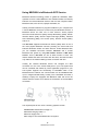
The CE mark as shown above displayed on all FuzzyScan series bar code scanners indicates that this
product has been tested in accordance with the procedures given in European Council R&TTE Directive
(99/5/EC) and confirmed to comply with the European Standard EN 301 489-17, EN 300 328-2, EN
50371, EN 60950.
פ܅ሽंᘿࡩሽᖲጥᙄऄ
รԼԲය ᆖীڤᎁᢞٽհפ܅୴᙮ሽᖲΔॺᆖױΔֆΕᇆࢨࠌ݁ृشլᖐ۞᧢ޓ᙮Εף
Օפࢨ᧢ޓૠհࢤ֗פ౨Ζ
รԼය פ܅୴᙮ሽᖲհࠌشլᐙଆڜ٤֗եឫٽऄຏॾΙᆖ࿇ڶեឫွழΔᚨܛمೖ
شΔࠀޏ۟ྤեឫழֱᤉᥛࠌشΖ
ছႈٽऄຏॾΔਐࠉሽॾࡳ܂ᄐհྤᒵሽॾΖפ܅୴᙮ሽᖲႊٽ࠹ݴऄຏॾࢨՠᄐΕઝᖂ֗᠔᛭ش
ሽंᘿ୴ࢤሽᖲໂհեឫΖ
Table of Contents
International Edition, Rev. B
Getting Started ............................................................................... 1
Getting Familiar with MBC6890 Cordless Imager.................... 2
Decide the Radio Link Mode ................................................... 4
Preparations Before Using...................................................... 5
Using MBC6890 Cordless Imager ................................................. 7
Using MBC6890 with DB100 Smart Cradle............................. 8
Using MBC6890 via Bluetooth SPP Service ......................... 14
Establish SPP Master Connection ............................... 15
Establish SPP Slave Connection ................................. 19
Operations and Indications......................................................... 23
Useful Tips for Field Operation ............................................. 24
MBC6890 Major States During Operation ............................. 25
MBC6890 Indications............................................................ 26
Cradle Indications ................................................................. 28
Configure MBC6890 Cordless Imager ........................................ 29
Programming Procedures ..................................................... 30
Host Interface Selection........................................................ 31
Acknowledgement Setting .................................................... 31
Operation Control ................................................................. 32
Symbology Reading Control ................................................. 33
Keyboard Interface Control ................................................... 37
Serial Interface Control ......................................................... 38
Wand Emulation Control ....................................................... 39
Condensed DataWizard........................................................ 40
Appendix ...................................................................................... 45
Keyboard Function Code Table ............................................ 46
ASCII Input Shortcut ............................................................. 47
Barcode System Commands ................................................ 48
Barcode Option Codes.......................................................... 50
Getting Started
Thank you for choosing MBC6890 series Bluetooth Cordless Linear
Imager. The MBC6890 series cordless imagers are designed with
remarkable optical architecture and innovative functionality. By
incorporating Bluetooth£ 1.2 wireless technology which operates on the
2.4 GHz ISM band, the MBC6890 series is compatible with most
popular Bluetooth-enabled devices, such as PCs, laptops and PDAs,
and so on.
Moreover, the MBC6890 series comes with various models to meet
diverse application needs and requirements for :
Different Communication Coverage
z Regular
Working Range Model
This model equips the class 2 Bluetooth radio which provided
minimum 10 meters wireless operations. Thanks to the optimal RF
design, it also is possible to perform farther coverage depending on
the actual working environments.
z Long
Working Range Model
This model equips the class 1 Bluetooth radio which provided
wireless operations within a range from minimum 75 meters up to
100 meters, even possibly farther by depending on the actual
working environments.
Various Reading Performances
z High
Density Model
The optics and image process algorithm of this model has been
optimized to enable reading very high-density bar codes down to 3mil resolution at least.
z Long
Range Model
The surpassing reading performance enables this model not only to
read high-density bar codes, but also capture popular bar codes
with superior depths of field up to 12”.
The MBC6890 series delivers the ultimate convenience as well as the
freedom of mobility to meet your on-demand bar code scanning, which
is the most cost-effective cable replacement solution to empower your
business.
This User’s Guide provides installation and operation instructions for
MBC6890 series. If you need more information, please contact your
supplier or visit our website.
1
MBC6890 User’s Guide
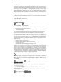
Getting Familiar with MBC6890 Cordless Imager
x MBC6890 Bluetooth Cordless Imager
Scan Window
Reset Button
Trigger
Unlock Hole
Imager LED
Buzzer
Hand Strip Hole
Battery Tank
Battery Cover
End Cap
Battery Cover Lock
Internal Connector
2
MBC6890 User’s Guide
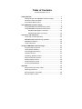
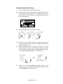
x DB100 Smart Cradle / DA100 Charging Cradle
Left LED
- Reserved
Right LED
- Reserved
Middle LED
[ DB100 ]
Connection Status Indication
[ DA100 ]
Power On Indication
[ DB100 ]
Multi Function Button
[ DA100 ]
Reserved
[ DB100 ]
Universal Legacy Output Port
DC Power Jack
[ DA100 ]
Reserved
3
MBC6890 User’s Guide
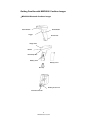
Decide the Radio Link Mode
The MBC6890 provides three (3) different radio link modes including
Pair Mode, SPP Slave and Master Modes. You may choose the
suitable one to implement your desired cordless scanning solution.
…… Note for Installation Engineer
The factory default setting of MBC6890 is in “Uninstall State” (Radio is
inactive.). Please choose one of the three (3) radio link modes for your
cordless scanning system before making any further actions. Once the
MBC6890 has been set to your desired radio link mode, it is necessary
for you to switch it back to “Uninstall State” before changing to different
radio link mode.
Pair Mode
Uninstall State
SPP Master Mode
SPP Slave Mode
Pair Mode: This is the simplest “Cable Replacement” solution, if
there is no Bluetooth device in your existing system. Using this
solution, users will benefit by upgrading the existing tethered
scanning platform to the cordless one without any effort. The
MBC6890 works with Smart Cradle to perform just as it is directly
wire-connected to a host PC through one of various legacy
interfaces such as PS/2 keyboard wedge, RS232, USB keyboard
and USB Serial.
SPP Master Mode: The MBC6890 is Master when it sends data to a
remote Bluetooth slave device such as a PCs, laptops, PDAs, etc.
Especially, the Auto Reconnecting capability can be performed in
this mode, even using the imager under PICONET connection.
SPP Slave Mode: The MBC6890 can be connected as “Slave”
when it sends data to a remote Bluetooth master device such as a
desktop PCs, laptops, and PDAs, which has to initialize the
communication.
…… Note for Field Operations
Please refer to the Chapter “Operations and Indications”. You will find
sufficient instructions for daily field operation of barcode scanning.
4
MBC6890 User’s Guide
Preparations Before Using
(1)
Have a remote Bluetooth system ready to work.
(2)
Open the battery cover then place the rechargeable batteries into
the battery tank. Please make sure the batteries are placed in
correct direction. (Do not charge non-rechargeable batteries, as it
may cause explosion.)
(3)
Close the battery cover and insert the end cap.
(4)
Connect the power supply unit with an AC outlet. Then, plug the
DC plug of the power supply unit into the DB100 smart cradle or
DA100 charging cradle.
(5)
Placing the imager onto the DB100 smart cradle or DA100
charging cradle for battery charging. Please make sure to hear
one short beep for reliable contact. The MBC6890 batteries have
to be charged at least 4-5 hours for the first time use.
(6)
Before you start using MBC6890, please make sure the
batteries are fully charged, then initialize the imager by poking
the Reset Button for the first time use.
5
MBC6890 User’s Guide
6
MBC6890 User’s Guide
Using MBC6890 Cordless Imager
The MBC6890 cordless imager has to establish communication with a
host system for data transmission. There are several ways for
connecting MBC6890 to the host system:
By using with the DB100 smart cradle, through one of legacy output
interfaces such as PS/2 keyboard wedge, RS232 serial interface,
USB keyboard interface and USB serial interface and so on.
By means of Bluetooth wireless communication via SPP master
service or SPP slave service.
To meet different requirements, the MBC6890 provides following two
operation modes:
Normal Mode
Under normal mode (default setting), when the radio link between the
MBC6890 and the host system is built, the MBC6890 transmits each
scanned data right after scanning the bar code. However, MBC6890
can not scan any bar code data while losing its connection with the
remote host system due to out of range. You might enable the option
of “Out-of-range Scanning” to have MBC6890 stored the scanned
data even the imager is out of range.
Batch Mode
Under batch mode, the MBC6890 can store the scanned data
without building the radio link with a remote host system.
For above-mentioned Out-of-range Scanning and Batch Mode, the
MBC6890 can store the scanned data into the buffer on a FIFO basis
until transmission is initialized or buffer memory is full. Nominally, the
imager will store up to 2,000 EAN-13 labels.
7
MBC6890 User’s Guide
Using MBC6890 with DB100 Smart Cradle
The MBC6890 works with DB100 smart cradle to perform just as it is
directly wire-connected to a host PC through one of legacy interfaces
such as PS/2 keyboard wedge, RS232 serial, USB keyboard and USB
serial. The “Pair Mode” scanning system is the most convenient “Cable
Replacement” solution, if there is no Bluetooth device in your existing
system. Using this solution, users could benefit by instant upgrading
the existing tethered scanning platform to the cordless one without any
effort.
Moreover, a special-designed Auto Reconnecting feature is provided
by MBC6890 under pair mode. If the radio link between the imager and
its paired smart cradle is lost, the automatic radio re-build process will
be activated immediately. It’s no need for user to re-build the radio
connection manually.
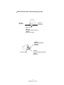
If several MBC6890 sets have been installed in the same area, users
may not be able to easily identify each imager and its paired smart
cradle. The paging function will help users to locate or identify the
paired imager and smart cradle with ease.
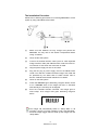
Paging Command
Paging
Short press on
multi function button
Paging
The required parts to form such a scanning system include:
MBC6890 cordless linear imager x 1
DB100 smart cradle x 1,
Power supply unit x 1
A selected interface cable
(such as PS/2 keyboard wedge Interface cable, RS232 serial
interface cable, USB keyboard interface cable, USB serial
Interface cable, or other interface cables)
8
MBC6890 User’s Guide
The Installation Procedure
Please refer to following procedures for connecting MBC6890 to a host
system by using with DB100 smart cradle:
(1)
Make sure that batteries are fully charged and placed into
MBC6890. You may refer to the Section “Preparations Before
Using” for details.
(2)
Power off the host system.
(3)
Connect the desired interface cable (such as: PS/2 keyboard
wedge interface cable) with DB100 smart cradle and host PC.
You will hear a ‘click’ when the connection is made.
(4)
Plug the power supply unit into an AC outlet.
(5)
Plug the DC plug of power supply unit into the DB100 smart
cradle. The radio link condition between imager and cradle will
be presented by the status LED of cradle. Please refer to
Section “DB100 Smart Cradle Indications” for details.
(6)
Power on the host system.
(7)
Check that MBC6890 gives alternating red-green blinks, means
it is in “Uninstall” state. If the imager has been in “Uninstall”
state already, the next step can be skipped.
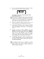
(8)
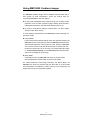
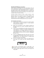
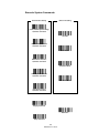
Scan the “Uninstall” barcode command. The imager gives 4
short beeps. Then imager LED gives alternating red-green
blinks.
Uninstall Command
The imager will automatically switch to “Sleep State” in 30
seconds, if there’s no further operation under “Uninstall State”.
Press the imager trigger switch to wake up the imager from the
“Sleep State”.
9
MBC6890 User’s Guide
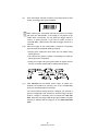
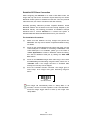
(9)
Scan “Pair Mode” barcode command. The imager gives 2 short
beeps, and imager LED gives red blinks.
Pair Mode Command
After scanning the “Pair Mode” barcode command, the imager
will enter into “Sleep State”, if the imager is not placed on the
cradle within 10 seconds. You can press the trigger switch to
revert it to pairing process. If you want to switch it back to
“Uninstall State”, please press and hold the trigger switch for 2
seconds.
(10)
Place the imager on the cradle within 10 seconds. The pairing
process will be automatically starting as below:
Imager gives continuous short clicks and red blinks during
pairing process.
You will hear the special 4 beeps in ascending tone. Now the
pairing process is completed.
Finally, the imager LED gives green blinks at regular interval,
and the connection status LED of cradle becomes green.
Pair Mode Command
On Cradle
(11)
Pairing OK
Paired
Take MBC6890 off the DB100 smart cradle. To select your
desired host interface by scanning one of the corresponding
quick set commands listed in next page.
If the host interface setting has been changed, you will hear a
special “Configuration OK” sound first. And the imager will give
another 4 beeps in ascending tone to indicate the radio link
built. After that, the imager LED will give green blinks at regular
intervals to indicate that the imager is in the radio-connected
state.
10
MBC6890 User’s Guide
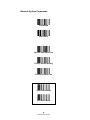
x Host Interface Quickset Command
PC/AT, PS/2 Keyboard Wedge
Quick Set Command
Keyboard Replacement
Quick Set Command
RS-232 Serial Interface
Quick Set Command
USB Keyboard Interface
Quick Set Command
USB Serial Interface
Quick Set Command
If the USB serial interface is selected, you have to install the
USB virtual COM driver in your host system before using the
imager. You may obtain the software driver from your supplier or
download it from our web site.
11
MBC6890 User’s Guide
Enable Out-of-Range Scanning
Under normal mode (default setting), when the radio link between the
MBC6890 and the host system is built, the MBC6890 transmits each
scanned data right after scanning the bar code label. However, the
MBC6890 can not scan any bar code data while losing its connection
with the remote host system due to out of range. You might enable the
option of “Out-of-range Scanning” to have MBC6890 stored the
scanned data even the imager is out of range. To enable this function,
please refer and follow the programming procedures.
When the MBC6890 is out of range, you will hear 4 beeps in
descending tone to indicate the radio connection lost. Then, the
MBC6890 gives red blinks at regular interval. You still can scan the bar
code even the radio connection has been discontinued. When a bar
code is saved successfully, a good read beep sounds and the LED
flashes green. When the memory buffer is full, the MBC6890 will give a
long beep and the LED flashes red.
When the MBC6890 enters into the working range, the data
transmission is triggered right after the radio link is rebuilt automatically.
You will hear 4 beeps in ascending tone to indicate the radio link built.
Following two short beeps, the MBC6890 gives continuous short clicks
and red blinks during the transmission process. After data transmission
is completed, the imager indicates four short beeps.
12
MBC6890 User’s Guide
Activate Batch Mode
You can activate batch mode to have MBC6890 stored scanned data
without building the connection with a remote host system.
To enable this function, please scan “Enter Batch Mode” quick set
command. When a bar code is saved successfully, a good read beep
sounds and the LED flashes green. When the memory buffer is full, the
MBC6890 will give a long beep and the LED flashes red.
Once you scan “Enter Batch Mode” quick set command, the
pre-connected radio link will be discontinued and the MBC6890
will enter batch mode.
You can trigger the data transmission by scanning “Exit Batch Mode”
quick set command. After that, the radio link will be rebuilt
automatically. You will hear 4 beeps in ascending tone to indicate the
radio link built. Following two short beeps, the MBC6890 gives
continuous short clicks and red blinks during the transmission process.
After data transmission is completed, the imager indicates four short
beeps.
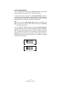
Enter Batch Mode
Quick Set Command
Exit Batch Mode
Quick Set Command
13
MBC6890 User’s Guide
Using MBC6890 via Bluetooth SPP Service
Bluetooth wireless technology works on global RF standards, which
operates on the 2.4 GHz ISM band. This enables wireless connectivity
between the remote Bluetooth devices and the host computer built-in
Bluetooth radio, such as PCs, laptops and PDAs, etc.
Usually, all actions between a program installed on your computer and
a remote Bluetooth device are carried out by the Bluetooth services. A
Bluetooth device can offer one or more services. These popular
services include Serial Port (SPP), Dail-Up Networking (DUN), Human
Interface Device (HID), Generic Object Exchange (GOEP), Personal
Area Networking (PAN), Lan Access (LAP), Generic Access (GAP),
and so on.
The MBC6890 supports the Serial Port Service (SPP) which is one of
the most popular Bluetooth services providing the serial radio link
between Bluetooth master and slave devices. Under Bluetooth SPP,
you can establish connection between MBC6890 and a remote
Bluetooth host system by using SPP master service or SPP slave
service. That is, MBC6890 can act as either master or slave. The
master initiates the radio connection with the slave, whereas the slave
only waits for the master initiating a radio connection with him.
Usually, the resident Bluetooth drivers will configure the SPP
connection as one of the virtual COM ports in your host system that
can be controlled and utilized by user’s application programs. If your
host system supports the functionality of PICONET which is the
Bluetooth device network, the communication can be established with
up to 7 imagers simultaneously. Usually, once a PICONET is formed, a
desktop or laptop PC equipped with Bluetooth radio will act as the
master while the others act as slaves for the duration of the PICONET
connection.
The required parts to form such a scanning systems include :
MBC6890 cordless linear imager x 1
DA100 charging cradle x 1
Power supply Unit x 1
A ready-to-use remote Bluetooth host system
14
MBC6890 User’s Guide
Establish SPP Master Connection
While configuring the MBC6890 to be used in SPP Master mode, the
Imager will initiate the connection to the remote Bluetooth host system.
The special-designed Auto Reconnecting feature is provided by
MBC6890 under this mode. If the radio link is lost, the automatic radio
re-build process will be activated immediately. It’s no need for user to
re-build the radio connection manually.
Generally speaking, Widcomm provides complete Windowś based
Bluetooth software and its stacks have been broadly adopted by the
Bluetooth industry. The following procedures of installation example
described how to connect MBC6890 to a remote host system in
Windows 2000 with Widcomm Bluetooth driver for your reference.
The Installation Procedures
(1)
Please prepare a 12-character barcode which contains the MAC
address (Bluetooth address) information of remote Bluetooth
host system before installation.
(2)
Make sure that batteries are fully charged & placed into
MBC6890. Please refer to Section “Preparations Before Using”
for details.
(3)
Power on your remote Bluetooth host system and make sure the
virtual COM port is available for connecting to MBC6890. If the
virtual COM port is not available, please go to the folder of
“Local Services” located in Bluetooth advanced setting, then
add an additional serial port service by clicking the “Add Serial
Services” button.
(4)
Power on the MBC6890 imager within radio range. Then check
that MBC6890 gives alternating red-green blinks, means it is in
“Uninstall” state. If the imager has been in “Uninstall” state
already, the next step can be skipped.
(5)
Scan the “Uninstall” barcode command. The imager gives 4
short beeps. Then imager LED gives alternating red-green
blinks.
Uninstall
Quick Set Command
The imager will automatically switch to “Sleep State” in 30
seconds, if there’s no further operation under “Uninstall State”.
Press the imager trigger switch to wake up the imager from
“Sleep State”.
15
MBC6890 User’s Guide
(6)
Scan the “SPP Master Mode” barcode command, the imager
gives 2 short beeps and imager LED gives red blinks.
SPP Master Mode
Quick Set Command
After scanning the “SPP Master Mode” barcode command, the
imager will enter “Sleep State”, if the radio link is not built within
1 minute. You can press the trigger switch to revert it to SPP
Master process. If you want to switch it back to “Uninstall State”,
please press and hold the trigger switch for 2 seconds.
(7)
<< Set the MAC Address of Remote Bluetooth Device >>
Scan a 12-character barcode to obtain the MAC address of the
remote Bluetooth host system. The imager gives one beep, then
the imager LED blinks short red light continuously during the
radio building process. If the PIN Code or Passkey is requested
for security connection, please enter “00000000”.
(8)
The MBC6890 imager gives 4 beeps in ascending tone to
indicate the radio link built. After that, the imager LED gives
green blinks at regular interval to indicate that the imager is in
radio-connected state.
The installation procedures will vary depending on different
remote Bluetooth host systems, operating systems and
Bluetooth drivers. Please follow the respective procedures to
build the connection accordingly.
16
MBC6890 User’s Guide
Enable Out-of-Range Scanning
Under normal mode (default setting), when the radio link between the
MBC6890 and the host system is built, the MBC6890 transmits each
scanned data right after scanning the bar code label. However, the
MBC6890 can not scan any bar code data while losing its connection
with the remote host system due to out of range. You might enable the
option of “Out-of-range Scanning” to have MBC6890 stored the
scanned data even the imager is out of range. To enable this function,
please refer and follow the programming procedures.
When the MBC6890 is out of range, you will hear 4 beeps in
descending tone to indicate the radio connection lost. Then, the
MBC6890 gives red blinks at regular interval. You still can scan the bar
code even the radio connection has been discontinued. When a bar
code is saved successfully, a good read beep sounds and the LED
flashes green. When the memory buffer is full, the MBC6890 will give a
long beep and the LED flashes red.
When the MBC6890 enters into the working range, the data
transmission is triggered right after the radio link is rebuilt automatically.
You will hear 4 beeps in ascending tone to indicate the radio link built.
Following two short beeps, the MBC6890 gives continuous short clicks
and red blinks during the transmission process. After data transmission
is completed, the imager indicates four short beeps.
17
MBC6890 User’s Guide
Activate Batch Mode
You can activate batch mode to have MBC6890 stored scanned data
without building the connection with a remote host system.
To enable this function, please scan “Enter Batch Mode” quick set
command. When a bar code is saved successfully, a good read beep
sounds and the LED flashes green. When the memory buffer is full, the
MBC6890 will give a long beep and the LED flashes red.
Once you scan “Enter Batch Mode” quick set command, the
pre-connected radio link will be discontinued and the MBC6890
will enter batch mode.
You can trigger the data transmission by scanning “Exit Batch Mode”
quick set command. After that, the radio link will be rebuilt
automatically. You will hear 4 beeps in ascending tone to indicate the
radio link built. Following two short beeps, the MBC6890 gives
continuous short clicks and red blinks during the transmission process.
After data transmission is completed, the imager indicates four short
beeps.
Enter Batch Mode
Quick Set Command
Exit Batch Mode
Quick Set Command
18
MBC6890 User’s Guide
Establish SPP Slave Connection
While configuring the MBC6890 to be used in SPP Slave mode, the
imager will only wait for the connection request issued by the remote
Bluetooth master system to establish the radio link. Once the pre-built
radio link is lost, user has to re-build the radio link manually.
Generally speaking, Widcomm provides complete Windowś based
Bluetooth software and its stacks have been broadly adopted by the
Bluetooth industry. The following procedures of installation example
described how to connect MBC6890 to a remote host system in
Windows 2000 with Widcomm Bluetooth driver for your reference.
The Installation Procedures
(1)
Make sure that batteries are fully charged and placed into
MBC6890. You may refer to Section “Preparations Before Using”
for details.
(2)
Power on the remote Bluetooth host system and make sure the
virtual COM port is available for connecting to MBC6890. If the
virtual COM port is not available, please go to the folder of
“Client Applications” located in Bluetooth advanced setting,
then add an additional COM port by clicking the “Add COM
Port” button.
(3)
Power on the MBC6890 imager within radio range. Then check
that MBC6890 gives alternating red-green blinks, means it is in
“Uninstall” state. If the imager has been in “Uninstall” state
already, the next step can be skipped.
(4)
Scan the “Uninstall” barcode command. The imager gives 4
short beeps. Then imager LED gives alternating red-green
blinks.
Uninstall
Quick Set Command
The imager will automatically switch to “Sleep State” in 30
seconds, if there’s no further operation under “Uninstall State”.
Press the imager trigger switch to wake up the imager from
“Sleep State”.
19
MBC6890 User’s Guide
(5)
Scan the “SPP Slave Mode” barcode command, the imager
gives 2 short beeps and imager LED gives red blinks.
SPP Slave Mode
Quick Set Command
Your imager is now ready to be discovered by a remote
Bluetooth master device.
After scanning the “SPP Slave Mode” barcode command, the
imager will enter “Sleep State”, if the radio link is not built within
1 minute. You can press the trigger switch to revert it to SPP
Slave process. If you want to switch it back to “Uninstall State”,
please press and hold the trigger switch for 2 seconds.
(6)
Execute the Bluetooth Discovery procedure from the host
system equipped with the remote Bluetooth master device.
(7)
Check whether "MBC6890" is shown among the discovered
Bluetooth devices in your host system. For example, the device
name “CINO MBC6890” will be shown on “Found Bluetooth
Devices”
(8)
Establish the radio link between MBC6890 and remote
Bluetooth master system. If the PIN Code or Passkey is
requested for security connection, please enter “00000000”.
Double click the “CINO MBC6890” on the found Bluetooth
devices. You will see the “CINO SPP” service on the imager.
Double click the “CINO SPP” service to establish the connection
between MBC6890 and remote Bluetooth master system.
(9)
The MBC6890 imager gives 4 beeps in ascending tone to
indicate the radio link built. After that, the imager LED will give
green blinks at regular intervals to indicate that the imager is in
the radio-connected state.
The installation procedures will vary depending on different
remote Bluetooth host systems, operation systems and
Bluetooth drivers. Please follow the respective procedures to
build the connection accordingly.
20
MBC6890 User’s Guide
Enable Out-of-Range Scanning
Under normal mode (default setting), when the radio link between the
MBC6890 and the host system is built, the MBC6890 transmits each
scanned data right after scanning the bar code label. However, the
MBC6890 can not scan any bar code data while losing its connection
with the remote host system due to out of range. You might enable the
option of “Out-of-range Scanning” to have MBC6890 stored the
scanned data even the imager is out of range. To enable this function,
please refer and follow the programming procedures.
When the MBC6890 is out of range, you will hear 4 beeps in
descending tone to indicate the radio connection lost. Then, the
MBC6890 gives red blinks at regular interval. You still can scan the bar
code even the radio connection has been discontinued. When a bar
code is saved successfully, a good read beep sounds and the LED
flashes green. When the memory buffer is full, the MBC6890 will give a
long beep and the LED flashes red.
When the MBC6890 enters into the working range, the data
transmission is triggered right after the radio link is rebuilt manually.
You will hear 4 beeps in ascending tone to indicate the radio link built.
Following two short beeps, the MBC6890 gives continuous short clicks
and red blinks during the transmission process. After data transmission
is completed, the imager indicates four short beeps.
21
MBC6890 User’s Guide
Activate Batch Mode
You can activate batch mode to have MBC6890 stored scanned data
without building the connection with a remote host system.
To enable this function, please scan “Enter Batch Mode” quick set
command. When a bar code is saved successfully, a good read beep
sounds and the LED flashes green. When the memory buffer is full, the
MBC6890 will give a long beep and the LED flashes red.
Once you scan “Enter Batch Mode” quick set command, the
pre-connected radio link will be discontinued and the MBC6890
will enter batch mode.
You can trigger the data transmission by scanning “Exit Batch Mode”
quick set command. After that, please establish the radio link between
MBC6890 and remote host system. You will hear 4 beeps in ascending
tone to indicate the radio link built. Following two short beeps, the
MBC6890 gives continuous short clicks and red blinks during the
transmission process. After data transmission is completed, the imager
indicates four short beeps.
Enter Batch Mode
Quick Set Command
Exit Batch Mode
Quick Set Command
22
MBC6890 User’s Guide
Operations and Indications
The MBC6890 has two indicators, LED and buzzer. They will provide
various indications depending on the actual operating conditions and
states. you may obtain necessary information to understand all details
by referring to following sections described in this Chapter, including:
Useful Tips for Field Operation
MBC6890 Major Sates During Operation
MBC6890 Indications
Cradle Indications
23
MBC6890 User’s Guide
Useful Tips for Field Operation
Please refer following four useful tips for your field operation :
4 descending-tone beeps
When you heard the special 4 descending-tone beeps, it means
the imager has lost the radio link already. This condition mostly
happens when you go out of the radio covering range. And the
imager LED will give red blinks at regular interval to indicate
Radio Disconnected state.
4 ascending-tone beeps
When you heard the special 4 ascending-tone beeps, it means
the radio link between imager and remote Bluetooth device has
been re-built already. This condition mostly happens when you
re-enter the radio covering range. And the imager LED will give
green blinks at regular interval to indicate Radio Connected
state.
Paging command
Occasionally you may not be able to locate your MBC6890,
especially in a job session which requires constant moving
around. The “Page” function (only available for “Pair Mode”
Connection) will help you to locate the imager.
Battery charging
The batteries inside the imager will be charged when imager is
placed on the cradle. If the imager indicates “Battery Power Low”
or “Battery Power Extremely Low”, please charge the batteries as
soon as possible.
DO NOT CHARGE NON-RECHARGEABLE BATTERIES,
AS IT MAY CAUSE EXPLOSION.
24
MBC6890 User’s Guide
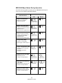
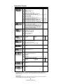
MBC6890 Major States During Operation
Once the scanning system is properly set up, MBC6890 will always be
under one of the following Operational States:
Indications
State & Actions
LED
Beeper
1. Radio Uninstall State
Æ Radio link not installed
Æ Install the radio link
alternating
red & green blinks
2. Radio Connected State
Æ Radio link installed already, the
imager is connected to a remote
Bluetooth device
Æ Ready to scan a regular barcode
1 green blink at
regular interval
3. Radio Disconnected State
Æ Radio link has been installed
already, but the imager is not
connected by any remote
Bluetooth device
Æ Re-enter radio covering range
1 red blink at
regular interval
4. Imager Sleep State
Æ Imager is in “Sleep State”
Æ Press trigger to wake imager up
5. Under-configuration State
Æ Imager is under configuration
procedure
Æ Complete configuration
procedure
steady red
6. Battery Power Low State
Æ Batteries power low
Æ Charge or change batteries
1 red blink at
regular interval
1 beep at
regular interval
8 red blinks
8 beeps
7. Battery Power Extremely
Low State
Æ Batteries power extremely low
Æ Charge or change batteries
8. Battery No Power State
Æ Batteries lost power completely
Æ Charge or change batteries
25
MBC6890 User’s Guide
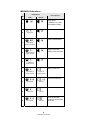
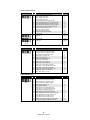
MBC6890 Indications
Indications
No
LED
Descriptions
Beeper
“Sleep State”,
or “Batteries no power”,
or No batteries inside
1
“Under Configuration”
2
steady red
“Radio Uninstall State”
3
4
alternating
red & green blinks
“Radio Connected”
(Ready to scan barcode)
1 green blink at
regular interval
“Radio Disconnected”
5
1 red blink at
regular interval
“Battery power low”
6
1 red blink at
regular interval
1 beep at
regular interval
“Power extremely low”
7
8 red blinks
8 beeps
Time out warning
8
9
1 red blink
2 red blinks
1 beep
2 beeps
Receiving the NAK
signal from smart cradle
or host PC
26
MBC6890 User’s Guide
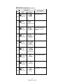
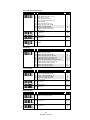
MBC6890 Indications (Continued)
Indications
No
LED
Descriptions
Beeper
Configuration fail
10
3 red blinks
3 beeps
“Good Read” beep
11
12
1 green blink
1 green blink
1 good read beep
1 ACK beep
Receiving ACK signal
from smart cradle or
host PC
Power on indication
13
1 green blink
power-on reset
beeps
Radio connection built
14
1 green blink
4 beeps in
ascending tone
Radio connection lost
15
1 red blink
4 beeps in
descending tone
Cradle paging Imager
16
10 red blinks
page beeps
Imager paging Cradle
17
10 red blinks
page beeps
Configuration successful
18
1 green blink
configuration OK
beeps
27
MBC6890 User’s Guide
Cradle Indications
Right LED
:
Reserved
Left LED
:
Reserved
Middle LED :
DB100 - Connection status indication
DA100 - Power on Indication
Middle LED of DB100 Smart Cradle
Indications
No
LED
Descriptions
Beeper
“Sleep State”,
or “Battery no power”,
or No battery inside
1
Steady red
“Under Configuration”
2
Steady green
Configuration successful
3
Steady green
“Radio Uninstall State”
4
red & green blinks
“Radio Connected”
5
Steady green
“Radio Disconnected”
6
Steady red
Radio connection built
7
Steady green
4 beeps in
ascending tone
Radio connection lost
8
Steady red
4 beeps in
descending tone
Middle LED of DA100 Charging Cradle
Indications
No
LED
Descriptions
Beeper
Cradle ready
(Power On)
1
Steady green
28
MBC6890 User’s Guide
Configure MBC6890 Cordless Imager
The FuzzyScan bar code commands are specially designed for field
programming convenience. All MBC6890 series cordless linear
imagers can take this way to make detailed configuration.
Before configuring your imager, please understand the command
structure and programming procedures in advance. The bar code
commands include System Command, Family Code and Option Code
for programming purpose.
System Command
The System command is the highest level bar code command which
directs the imager to perform immediate operations, such as
entering/exiting programming mode, listing system information,
recovering to factory preset configurations, quick setting popular
configuration, and so on. Please note that all system commands will
take a few seconds to complete the desired operation. You must wait
for the completion sound before scanning another bar code.
Family Code
The Family Code is scanned to select the user desired programming
family. FuzzyScan MBC6890 codeless imager provide more than 100
programming family to meet any specific requirements.
Option Code
The Option Code is a set of bar code commands represented by “0-9”,
“A-F” and finishing selection (FIN). For most setting, you have to select
at least one option code following the family code selection to set your
desired configuration for the selected programming family.
This Chapter provides access to all the configuration setting for
MBC6890 series, including :
Programming Procedures
Host Interface Selection
Acknowledgement Setting
Operation Control
Symbology Reading Control
Keyboard Interface Control
Serial Interface Control
Condensed DataWizard
29
MBC6890 User’s Guide
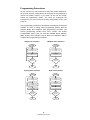
Programming Procedures
As you scan the bar code command to select the desired parameters,
all the final selected configurations will be stored in the FuzzyScan’s
internal non-volatile memory. If you power off the unit, the imager
retains all programming options. You need not re-program the
FuzzyScan if you want to keep the existing configurations for the next
power on.
The programming procedures of FuzzyScan are designed as simple as
possible for ease of setting. Most programming families take the
simplest Single Scan Selection (SS) programming procedure. But
several programming families have more complex and flexible
programmable options, and you must take Multiple Scans Selection
(MS), Cycling Scan Selection (CS) or Dual Level Selection (DS) to
complete their programming procedures.
Single scan selection
Multiple scans selection
Scan
“PROGRAM”
Scan
“PROGRAM”
Scan
One of Family Codes
Scan
One of Family Codes
Scan
One of Option Codes
Scan One or
Several Option Codes
Yes
Yes
Repeat
Selection
No
No
Scan
“END”
Scan
“END”
Cycling scan selection
Dual level selection
Scan
Scan
“PROGRAM”
“PROGRAM”
Scan
One of Family Codes
Scan
One of Family Codes
(1st) Scan
Several Option Codes
Scan
One of Option Codes
(2nd) Scan One or
Several Option Codes
Scan “FIN”
Yes
Repeat
Selection
Yes
Repeat
Selection
No
Repeat
Selection
No
Scan
“END”
Scan
“END”
30
MBC6890 User’s Guide
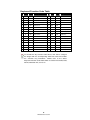
Host Interface Selection
Command
Host Interface
Selection
P.C.
Parameter Selection
Option
MS
MS
MS
MS
MS
MS
MS
MS
MS
MS
MS
MS
MS
MS
MS
MS
MS
MS
MS
MS
MS
MS
MS
MS
MS
MS
MS
MS
MS
MS
MS
MS
MS
MS
MS
MS
MS
MS
IBM PC/XT keyboard wedge
IBM PC/AT, PS/2 series keyboard wedge
Compaq, HP Vectra PC keyboard wedge
Apple ADB keyboard wedge
Standard/TTL RS232 peer-to-peer serial interface
Standard/TTL RS232 serial wedge interface
Wand emulation interface
Pseudo RS232 serial interface (3-wire TTL level)
PC/AT, PS/2 keyboard replacement
General Notebook PC keyboard wedge interface
General Notebook PC keyboard direct-link interface
IBM SureOne keyboard wedge interface
IBM SureOne standard RS232 serial interface
Laser emulation interface
USB keyboard (for Windows 98, XP, 2000 and iMac)
USB keyboard (for Windows XP, 2000)
IBM 5550 series keyboard wedge (6p)
SUN Microsystems Ultra 10 Workstation
IBM ThinkPad keyboard direct-link interface
IBM ThinkPad keyboard wedge interface
IBM PS/55 5576-001 (set 81) keyboard wedge interface
IBM PS/55 5576-002 (set 81) keyboard wedge interface
IBM PS/55 5576-003 (set 81) keyboard wedge interface
IBM PS/55 5576-A01 (set 1) keyboard wedge interface
IBM PS/55 5576-001 (set 8A) keyboard wedge interface
IBM PS/55 5576-002 (set 8A) keyboard wedge interface
IBM PS/55 5576-003 (set 8A) keyboard wedge interface
IBM PS/V PC, 5576-001 (set 82) keyboard wedge
IBM PS/V PC, 5576-002 (code set 82) keyboard wedge
IBM PS/V PC, 5576-003 (code set 82) keyboard wedge
IBM PS/V PC, 5576-A01 (code set 2) keyboard wedge
Hitachi Flora KB1100 keyboard wedge
Hitachi Flora KB3100 keyboard wedge
Compaq Desktop PC keyboard wedge
DOS/V keyboard direct link
Fujitsu FMV keyboard wedge
NEC NX Notebook direct link
NEC PC-98 keyboard wedge
00
01
04
05
06
07
08
09
10
13
14
15
16
17
18
19
1A
1B
84
87
70
71
72
73
74
75
76
77
78
79
80
81
82
83
85
86
89
87
Acknowledgement Setting
Command
P.C.
SS
SS
Parameter Selection
Bluetooth Acknowledgement
Receiving Acknowledgement
Option
0
1
ACK Setting
Bluetooth Acknowledgement
While taking this setting, the receiving confirmation will be performed by the Bluetooth handshaking
mechanism. The MBC6890 will give a “Good Read” beep after receiving the confirmation issued by
the internal Bluetooth module to identify the scanned data transmitted successfully.
Receiving Acknowledgement (Pair Mode only)
While taking this setting in pair mode, the receiving confirmation will be performed by the paired
smart cradle. The MBC6890 will take the special handshaking protocol to communicate with smart
cradle. Once reading a bar code, the imager will give a “Good Read” beep after receiving the
confirmation issued by the internal Bluetooth module first. If the smart cradle successfully received
the scanned data, MBC6890 will give an additional Acknowledgement (ACK) beep after
receiving the confirmation issued by the smart cradle. In case of MBC6890 didn’t receive the
confirmation after time out duration or received a NAK signal from the smart cradle, MBC6890 will
give the NAK beeps to remind user. Furthermore, the acknowledgement beeping tone can be set
by the user. Please refer to the “Buzzer Tone Adjustment” for details.
31
MBC6890 User’s Guide
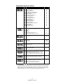
Operation Control
1Command
P.C.
Parameter Selection
Option
SS
SS
SS
SS
SS
SS
SS
SS
SS
SS
SS
SS
SS
SS
Buzzer tone - mute
Buzzer tone - low
Buzzer tone - medium
Buzzer tone - high
Buzzer tone - extremely high
Good-read beep before data transmission
Good-read beep after data transmission
Power-on beep
No power-on beep
Acknowledgement beeping tone - mute
Acknowledgement beeping tone - low
Acknowledgement beeping tone - medium
Acknowledgement beeping tone - high
Acknowledgement beeping tone - extremely high
0
1
2
3
4
5
6
7
8
9
A
B
C
D
SS
SS
Regular (standard) printing quality
Poor (critical) printing quality
If you select the “Poor printing quality” option, please
limit the “Readable bar code symbologies” and
“Minimum and Maximum reading length” of each
symbology to avoid error reading.
0
1
SS
SS
SS
SS
SS
SS
Disable
Immediate time out duration
Short time out duration
Medium time out duration
Long time out duration
Force Verification
0
1
2
3
4
5
Redundancy
(Scan Voting)
SS
SS
SS
SS
None
1 time
2 times
Auto Power Off
Duration
SS
SS
SS
SS
Short (around 2 seconds)
Medium (around 3-4 seconds)
Long (around 5-6 seconds)
Extremely long (around 7-8 seconds)
0
1
2
3
SS
SS
Disable
Enable
0
1
SS
SS
Dollar sign output as "$”
Dollar sign output as “д”
0
1
SS
0
SS
SS
None (Disable automatic sleep function)
For Connected State (On Line)
1 Minutes
3 Minutes
5 Minutes
User defined duration: 1-99 minutes (20 minutes)
For Disconnected State (Off Line)
1 Minute
5 Minutes
3 Minutes
10 Minutes
SS
SS
Disable
Enable
0
1
SS
SS
Disable
Enable
0
1
Buzzer Tone
Adjustment
Scanning Tolerance
Double Scan
Verification
3 times
4 times
5 times
0
1
2
3
4
5
Inverse Reading
Dollar Sign Control
Sleep Time Out
Control (Radio Off)
SS
SS
SS
SS
1
2
3
4, (2 digits)
5
6
7
8
Low Power Warning
Out-of-range
Scanning
Sleep Time Out Control
If the imager has not been used within the preset time out duration, it will automatically enter
“Sleep State” for power saving purpose. User may disable this function by setting the time out
duration to “None”.
On-cradle state
While the imager is placed on the cradle, the sleep time out duration for both Disconnected and
Connected state will be changed to 60 minutes automatically.
32
MBC6890 User’s Guide
Symbology Reading Control
User Defined Symbol ID
Command
Symbol ID
- 1 character -
nd
P.C.
Parameter Selection
Option
2
Option
DS
DS
DS
DS
DS
DS
DS
DS
DS
DS
DS
DS
DS
DS
DS
DS
DS
Code 128 (default=B)
UCC/EAN-128 (default=C)
UPC-A (default=A)
EAN/JAN/CAN-13 (default=F)
Codabar/NW-7 (default=D)
Code 39/Code 32 (default=G)
Code 93 (default=H)
Standard/Industrial 2 of 5 (default =1)
Interleaved 2 of 5 (default=J)
Matrix 2 of 5 (default=K)
China Postal Code (default=L)
German Postal Code (default=M)
IATA (default=O)
Code 11 (default=P)
MSI/Plessey (default=R)
UK/Plessey (default=S)
Telepen (default=T)
00
01
02
03
04
05
06
07
08
09
10
11
12
13
14
15
16
(1 Character)
(1 Character)
(1 Character)
(1 Character)
(1 Character)
(1 Character)
(1 Character)
(1 Character)
(1 Character)
(1 Character)
(1 Character)
(1 Character)
(1 Character)
(1 Character)
(1 Character)
(1 Character)
(1 Character)
DS
DS
UPC-E (default=E0)
EAN-8 (default=FF)
00
01
[1-2 chars], [FIN]
[1-2 chars], [FIN]
Symbol ID
- 2 character -
Readable Symbology Setting
Command
Readable Symbology
Setting
P.C.
SS
CS
CS
CS
CS
CS
CS
CS
CS
CS
CS
CS
CS
CS
Parameter Selection
Automatic discrimination
Code 128, UCC/EAN-128
UPC-A
UPC-E
EAN/CAN/JAN-13
EAN/CAN/JAN-8
Codabar/NW-7
Code 39/Code 32, HIBC
Code 25 Family, IATA
Code 93
Code 11
MSI/Plessey
UK/Plessey
Telepen
Option
00
01
02
03
04
05
06
07
08
09
10
11
12
13
Code 39 & Code 32 Setting
Command
Code 39 Family
Setting
P.C.
Parameter Selection
Option
SS
SS
SS
SS
SS
SS
SS
SS
SS
SS
SS
Select Standard Code 39 format
Select Full ASCII Code 39 format
Select Code 32 (Italian Pharmaceutical) format
Disable start/stop symbol transmission
Enable start/stop symbol transmission
Disable Code 32 leading A transmission
Enable Code 32 leading A transmission
Disable MOD 43 check digit verification
Enable MOD 43 check digit verification
Disable check digit transmission
Enable check digit transmission
SS
MS
Default (04)
01-Maximum
FIN
(2 digits)
SS
MS
Default (98)
98-Minimum
FIN
(2 digits)
0
1
2
3
4
5
6
7
8
9
A
Code 39 Min. Length
Code 39 Max. Length
33
MBC6890 User’s Guide
Codabar & NW-7 Setting
Command
Codabar Setting
P.C.
Parameter Selection
Option
SS
SS
SS
SS
SS
SS
SS
SS
SS
SS
SS
SS
SS
Select Codabar standard format
Select Codabar ABC format
Select Codabar CLSI format
Select Codabar CX format
Disable start/stop symbol transmission
Enable ABCD/ABCD start/stop symbol transmission
Enable abcd/abcd start/stop symbol transmission
Enable ABCD/TN*E start/stop symbol transmission
Enable abcd/tn*e start/stop symbol transmission
Disable check digit verification
Enable check digit verification
Disable check digit transmission
Enable check digit transmission
SS
MS
Default (04)
01-Maximum
FIN
(2 digits)
SS
MS
Default (98)
98-Minimum
FIN
(2 digits)
0
1
2
3
4
5
6
7
8
9
A
B
C
Codabar Min. Length
Codabar Max.
Length
UPC Setting
Command
UPC Family Setting
P.C.
SS
SS
SS
SS
SS
SS
SS
SS
SS
SS
SS
SS
SS
SS
SS
SS
Parameter Selection
Select UPC without supplement digits
Select UPC with only 2 supplement digits
Select UPC with only 5 supplement digits
Select UPC with 2/5 supplement digits
Disable UPC-E expansion
Enable UPC-E expansion
Disable UPC standardization
Enable UPC standardization
Disable UPC numeric system
Enable UPC numeric system
Disable UPC-A check digit transmission
Enable UPC-A check digit transmission
Disable UPC-E check digit transmission
Enable UPC-E check digit transmission
Disable UPC “leading 1” portion
Enable UPC “leading 1” portion
Option
0
1
2
3
4
5
6
7
8
9
A
B
C
D
E
F
EAN/JAN/CAN Setting
Command
EAN/CAN/JAN
Setting
P.C.
SS
SS
SS
SS
SS
SS
SS
SS
SS
SS
SS
SS
SS
SS
SS
SS
Parameter Selection
Select EAN without supplement digits
Select EAN with only 2 supplement digits
Select EAN with only 5 supplement digits
Select EAN with 2/5 supplement digits
Disable EAN-8 expansion
Enable EAN-8 expansion
Disable EAN-13 check digit transmission
Enable EAN-13 check digit transmission
Disable EAN-8 check digit transmission
Enable EAN-8 check digit transmission
Disable ISBN/ISSN Conversion reading check
Enable ISBN/ISSN Conversion reading check
Enable ISBN Conversion reading check
Enable ISSN Conversion reading check
Set EAN/UPC supplement digits as optional
Set EAN/UPC supplement digits as necessary
34
MBC6890 User’s Guide
Option
0
1
2
3
4
5
6
7
8
9
A
B
C
D
E
F
Code 25 & German Post Setting
Command
Code 25 Setting
P.C.
Parameter Selection
Option
SS
SS
SS
SS
SS
SS
SS
SS
SS
SS
SS
Select any Code 25
Select Standard/Industrial 2 of 5 only
Select Matrix 2 of 5 only
Select Interleaved 2 of 5 only
Select Interleaved 2 of 5 S Code only
Select IATA only
Select China Postal Code only
Disable check digit verification
Enable check digit verification
Disable check digit transmission
Enable check digit transmission
SS
MS
Default (04)
01-Maximum
FIN
(2 digits)
SS
MS
Default (98)
98-Minimum
FIN
(2 digits)
SS
SS
Disable
Enable
0
1
2
3
4
5
6
7
8
9
A
Code 25 Min. Length
Code 25 Max. Length
0
1
German Postal
Setting
IATA Setting
Command
IATA Setting
P.C.
SS
SS
SS
SS
SS
SS
SS
SS
SS
SS
SS
Parameter Selection
Select 15-digit fixed length IATA checking
Select variable length IATA
Disable check digit verification
Enable check digit automatic verification
Enable S/N checking digit verification only
Enable CPN checking digit verification only
Enable CPN, Airline and S/N check digit verification
Disable start/stop symbol transmission
Enable start/stop symbol transmission
Disable check digit transmission
Enable check digit transmission
Option
0
1
2
3
4
5
6
7
8
9
A
Code 11 Setting
Command
P.S.
Parameter Selection
Option
Code 11 Setting
SS
SS
SS
SS
SS
Select 1-check digit verification
Select 2-check digit verification
Disable check digit transmission
Enable 1-check digit transmission
Enable 2-check digit transmission
SS
MS
Default (04)
01-Maximum
FIN
(2 digits)
SS
MS
Default (98)
98-Minimum
FIN
(2 digits)
0
1
2
3
4
Code 11 Min. Length
Code 11 Max. Length
Code 93 Setting
Command
P.C.
Parameter Selection
Option
SS
MS
Disable check digit transmission
Enable check digit transmission
SS
MS
Default (03)
01-Maximum
FIN
(2 digits)
SS
MS
Default (98)
98-Minimum
FIN
(2 digits)
0
1
Code 93 Setting
Code 93 Min. Length
Code 93 Max. Length
35
MBC6890 User’s Guide
MSI/Plessey Setting
Command
P.C.
Parameter Selection
Option
MSI/Plessey Setting
SS
SS
SS
SS
SS
SS
Select MOD 10 check digit
Select MOD 10-10 check digit
Select MOD 11-10 check digit
Disable check digit transmission
Enable 1-check digit transmission
Enable 2-check digit transmission
SS
MS
Default (04)
01-Maximum
FIN
(2 digits)
SS
MS
Default (98)
98-Minimum
FIN
(2 digits)
0
1
2
3
4
5
MSI/Plessey
Minimum Length
MSI/Plessey
Maximum Length
UK/Plessey Setting
Command
UK/Plessey Setting
P.C.
Parameter Selection
Option
SS
SS
SS
SS
SS
SS
Select UK/Plessey Standard Format
Select UK/Plessey CLSI Format
Disable Convert X to A-F
Enable Convert X to A-F
Disable check digit transmission
Enable check digit transmission
SS
MS
Default (04)
01-Maximum
FIN
(2 digits)
SS
MS
Default (98)
98-Minimum
FIN
(2 digits)
0
1
2
3
4
5
UK/Plessey
Minimum Length
UK/Plessey
Maximum Length
Code 128 & UCC/EAN 128 Setting
Command
P.C.
Parameter Selection
Option
SS
SS
Disable function code conversion
Enable function code conversion
SS
MS
Default (04)
01-Maximum
FIN
(2 digits)
SS
MS
Default (98)
98-Minimum
FIN
(2 digits)
0
1
Code128/EAN-128
Setting
Code128/EAN-128
Minimum Length
Code128/EAN-128
Maximum Length
Telepen Setting
Command
Telepen Setting
P.C.
Parameter Selection
Option
SS
SS
SS
SS
Select Telepen Numeric mode
Select Telepen Full ASCII mode
Disable check digit transmission
Enable check digit transmission
SS
MS
Default (04)
01-Maximum
FIN
(2 digits)
SS
MS
Default (98)
98-Minimum
FIN
(2 digits)
0
1
2
3
Telepen Min. Length
Telepen Max. Length
36
MBC6890 User’s Guide
Keyboard Interface Control
Command
Language Setting
Record Suffix
P.C.
Parameter Selection
Option
MS
MS
MS
MS
MS
MS
MS
MS
MS
MS
MS
MS
MS
MS
MS
MS
MS
MS
USA (QWERTY)
France (AZERTY)
Germany (QWERTZ)
United Kingdom - UK (QWERTY)
Canadian French (QWERTY)
Spain (QWERTY)
Sweden/Finland (QWERTY)
Portugal (QWERTY)
Norway (QWERTY)
Latin America (QWERTY)
Italy (QWERTY)
Netherlands (QWERTY)
Denmark (QWERTY)
Belgium (AZERTY)
Switzerland-Germany (QWERTY)
Iceland (QWERTY)
Japan (DOS/V)
Universal * (see note)
SS
SS
SS
SS
SS
MS
None
RETURN
TAB
SPACE
ENTER (Numeric Key Pad)
User defined character (1 character)
SS
MS
None
1-99 msec.
FIN
(2 digits)
SS
MS
None
1-99 msec.
FIN
(2 digits)
SS
MS
None
1-99 (X 5) msec.
FIN
(2 digits)
SS
SS
SS
“Caps Lock Off” State
“Caps Lock On” State
Auto Detect (PC/AT, PS/2, DOS/V KB interface only)
0
1
2
SS
SS
Enable ASCII 00-31 as KB function code output
Enable ASCII 00-31 as Ctrl-xx output
Refer to Keyboard Function Code Table for details
0
1
SS
SS
Disable keypad emulation
Enable numeric keypad output (Num Lock On)
O
1
SS
SS
SS
SS
Normal (neglect the upper/lower case control)
Inverse (change all outputs to inverse case)
Upper (force all outputs as upper case)
Lower (force all outputs as lower case)
0
1
2
3
00
01
02
03
04
05
06
07
08
09
10
11
12
13
14
15
16
99
0
1
2
3
4
5, (00 ~ 7F)
Character Frame
Control
Intercharacter Delay
Intermessage Delay
Caps Lock Control
Function Key
Emulation
Keypad Emulation
Upper/Lower Case
Control
Language Setting
The “Universal” option of language setting is only valid for PC/AT and PS/2 related keyboard
interfaces working under DOS or Windows environments. This option can perform unique
output without Caps Lock on/off (Output Style) concern. All transmitted data will follow the
original full ASCII form. You also need not worry about the upper/lower case control.
37
MBC6890 User’s Guide
Serial Interface Control
Command
P.C.
Parameter Selection
Option
SS
SS
Disable STX/ETX transmission
Enable STX/ETX transmission
SS
SS
SS
SS
SS
None
CR (0DH)
LF (0AH)
CRLF (0D0AH)
SS
SS
SS
SS
None (free running mode)
RTS/CTS (hardware handshaking)
ACK/NAK (software handshaking)
Xon/Xoff (software handshaking)
0
1
2
3
SS
SS
Disable
Enable
0
1
SS
MS
None
1-99 msec.
FIN
(2 digits)
SS
MS
None
1-99 (X 5) msec.
FIN
(2 digits)
SS
SS
SS
SS
SS
38.4K BPS
19.2K BPS
9600 BPS
4800 BPS
2400 BPS
1200 BPS
600 BPS
300 BPS
115.2K BPS
0
1
2
3
4
5
6
7
8
SS
SS
SS
SS
SS
SS
SS
SS
8, None, 1
8, Odd, 1
8, Even, 1
8, Space, 1
8, Mark, 1
8, None, 2
7, Odd, 1
7, Even, 1
7, Space, 1
7, Mark, 1
7, None, 2
7, Odd, 2
7, Even, 2
7, Space, 2
7, Mark, 2
0
1
2
3
4
5
6
7
8
9
A
B
C
D
E
SS
SS
SS
SS
SS
SS
MS
None
200 mseconds
500 mseconds
1 second
2 seconds
5 seconds
User defined duration (seconds)
0
1
STX/ETX Control
Record Suffix
Handshaking Protocol
TAB (09H)
SPACE (20H)
EOT (04H)
User defined character
(1 character : 00~7F)
0
1
2
3
4
5
6
7
Boundary Check
Intercharacter Delay
Intermessage Delay
Baud Rate (BPS)
Data Frame
Time Out Control
0
1
2
3
4
5
6, (2 digits)
Boundary Check
When enabling this function, the smart cradle will take more time to perform the boundary check
to ensure the reliable transmission. Please note that this will prolong the acknowledgement
response.
38
MBC6890 User’s Guide
Wand Emulation Control
Command
P.C.
Parameter Selection
Option
SS
SS
High level (5Vdc) on Bar (low level on Space)
Low level (0Vdc) on Bar (high level on Space)
0
1
SS
SS
High Level (5 Vdc)
Low Level (0 Vdc)
0
1
SS
SS
SS
SS
10 mseconds
15 mseconds
20 mseconds
25 mseconds
30 mseconds
50 mseconds
100 mseconds
0
1
2
3
4
5
6
SS
SS
Extremely Short
Short
Medium
Long
0
1
2
3
Narrow/Wide Ratio
SS
SS
SS
1:2
1:2.5
1:3
0
1
2
Code 39 Emulation
SS
SS
SS
Disable standard Code 39 emulation
Enable standard Code 39 skip emulation
Enable standard Code 39 replace emulation
0
1
2
Output Polarity
Initial Signal State
Margin Time
Module Time
39
MBC6890 User’s Guide
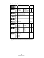
Condensed DataWizard
DataWizard is a powerful, artificial intelligence based data editing
expert system provided specially for the FuzzyScan family bar code
readers. Through DataWizard, you can process the scanned data prior
to the transmissions in many ways, such as: Insert, Delete, Match,
Verify, Substitute, Reorganize, and Repeat Transmission. It will help
you to transmit the scanned data to any specific format without
software modifications. Please refer to below for details.
Data Formatting and Editing
Preamble, Postamble, Data Length Transmission
There are maximum 15 characters can be added as Preamble or
Postamble. To enable the Data Length Transmission, a 2-digit data
length will be added after Preamble.
Symbology ID Transmission
To enable the Symbology ID Transmission, the “CINO Symbology
ID” or “AIM Symbology ID” will be added into the transmitted data. It
is very helpful for applications to identify the specific bar code by
symbology ID.
Data Formatter
The Data Formatter is used to edit the scanned raw data prior to the
transmission to the host computers. It allows you to select desired
bar code symbologies for formatter control, and provides Multipleposition Insertion and Multiple-character Insertion (maximum three
characters) in the identified position.
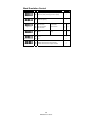
Data Verifier
The Data Verifier is used to provide advanced verification for errorfree scanning and working as an Embedded Data Transmitting
Filter. All scanned raw data must conform to the Identified Bar Code
Symbologies, Identified Data Length, and 1 to 3 Identified
Characters in the checking position. Otherwise, the FuzzyScan will
not transmit the data to the host computers or terminals, but will
issue 3 long beeps instead for error verification and skip the
scanned data.
Data Changer
The Data Changer is used to edit the scanned raw data prior to the
transmission to the host computers or terminals. It allows you to
select desired bar code symbologies for changer control, and
provides Multiple-position Substitute in the identified position.
Data Organizer
The Data Organizer is used to edit the scanned raw data prior to the
transmission to the host computers or terminals. It allows you to
select desired bar code symbologies for organizer control, and
provides maximum two identified positions to send the data forward
or backward. It also allows you to control the transmitted data
including or excluding the data of identification position.
40
MBC6890 User’s Guide
Preamble, Postamble, Data Length Setting
Command
P.C.
Parameter Selection
Option
SS
MS
None
1-15 characters
FIN
[00-7F], [FIN]
SS
MS
None
1-15 characters
FIN
[00-7F], [FIN]
SS
SS
Disable
Enable 2-digits data length transmission
If data length exceeds 99, 3-digit data length will be
transmitted
Preamble
Postamble
Data Length
Transmission
0
1
Data Formatter Setting
Command
P.C.
Formatter Control
nd
Parameter Selection
Option
2
SS
MS
MS
Disable
Select one bar code symbology
Select all bar code symbologies
FIN
(2 digits)
00
Option
SS
DS
Disable
Enable
FIN
(2 digits)
[1-3 chars], [FIN]
SS
DS
Disable
Enable
0
1
[1-3 chars], [FIN]
SS
DS
Disable
Enable
0
1
[1-3 chars], [FIN]
SS
DS
Disable
Enable
0
1
[1-3 chars], [FIN]
1st Insertion
2nd Insertion
3rd Insertion
4th Insertion
Data Verifier Setting
nd
Command
P.C.
Parameter Selection
Option
2
Option
Verifier Control
SS
MS
MS
Disable
Select one bar code symbology
Select all bar code symbologies
FIN
(2 digits)
00
SS
MS
Disable
Enable
FIN
(2 digits)
SS
DS
Disable
Enable
FIN
(2 digits)
[00-7F]
SS
DS
Disable
Enable
FIN
(2 digits)
[00-7F]
SS
DS
Disable
Enable
FIN
(2 digits)
[00-7F]
Identified Data
Length
1st Identified
Character
2nd Identified
Character
3rd Identified
Character
41
MBC6890 User’s Guide
Data Changer Setting
Option
nd
Command
P.C.
Parameter Selection
2
Option
Changer Control
SS
MS
MS
Disable
Select one bar code symbology
Select all bar code symbologies
FIN
(2 digits)
00
SS
DS
Disable
Enable
FIN
(2 digits)
[00-7F]
SS
DS
Disable
Enable
FIN
(2 digits)
[00-7F]
SS
DS
Disable
Enable
FIN
(2 digits)
[00-7F]
1st Substitute
2nd Substitute
3rd Substitute
Data Organizer Setting
nd
Command
P.C.
Parameter Selection
Option
2
Organizer Control
SS
MS
MS
Disable
Select one bar code symbology
Select all bar code symbologies
FIN
(2 digits)
00
SS
DS
Disable
Enable
FIN
(2 digits)
SS
DS
Disable
Enable
FIN
(2 digits)
SS
DS
Excluded the identified position
Included the identified position
1st Organization
2nd Organization
Option
0 (Forward)
1(Backward)
0 (Forward)
1(Backward)
0
1
Include/Exclude
Control
Symbology ID Transmission
Command
Symbology ID
Transmission
P.C.
Parameter Selection
Option
Disable all symbology ID
Enable prefix CINO symbology ID
Enable suffix CINO symbology ID
Enable both prefix and suffix CINO symbology ID
Enable prefix AIM symbology ID
Enable suffix AIM symbology ID
Enable both prefix and suffix AIM symbology ID
SS
SS
SS
SS
SS
SS
SS
0
1
2
3
4
5
6
Symbology ID Table :
Symbology
CINO ID
AIM ID
Symbology
CINO ID
AIM ID
UPC-A
A
E
Interleaved 2 of 5
J
I
Code 128
B
C
Matrix 2 of 5
K
S
UCC/EAN-128
C
C
China Postal Code
L
R
Codabar/NW-7
D
F
German Postal Code
M
X
UPC-E
E0
E
IATA
O
R
F
E
Code 11
P
H
EAN/JAN/CAN-13
EAN-8
FF
E
MSI/Plessy
R
M
Code 39/Code 32
G
A
UK/Plessy
S
P
Code 93
H
G
Telepen
T
B
Standard/2 of 5
I
S
Industrial 2 of 5
I
S
42
MBC6890 User’s Guide
Select a Bar Code Symbology
You can select one or all types of bar code symbologies to use
Condensed DataWizard for advanced transmission arrangement. If
you scan “00” to select all types, the MBC6890 will arrange all
incoming data to meet your pre-defined format. If you want to select
only one type bar code, please select one of the option code listed
below.
UPC-E : 03
Code 128 : 01
Code 11 : 10
Codabar/NW-7 : 06
Code 39 : 07
UPC-A : 02
EAN/CAN/JAN-8 : 05
Telepen : 13
UK/Plessey : 12
EAN/CAN/JAN-13 : 04
Code 32 : 07
MSI/Plessey : 11
UCC/EAN 128 : 01
Code 93 : 09
Code 25 Family : 08
Position Calculation
μData Formatterν
If there is a 5-character input data string, please refer to the following to
calculate the actual position for insertion :
x
00
x
x
01
x
02
03
x
04
05
μData Verifier, Data Replacer, Data Organizerν
If there is a 11-character data string, please refer to the following to
calculate the actual position for identification :
x
x
x
x
x
x
x
x
x
x
x
00
01
02
03
04
05
06
07
08
09
10
Application Example
If your bar code label is a 16-digit interleaved 2 of 5 which includes the
information of 6-digit date code, 6-digit serial number and 4-digit unit
price, you want MBC6890 to do the following for you without software
modification :
Apply only Interleaved 2 of 5 to the condensed DataWizard.
Check bar code is actually with 16-digit length.
Allow bar code output whose date code is leading with “9”.
Three outputs with “TAB” suffix.
The date code output should skip “9” and replaced it by “A”.
The serial number output should be led with “SN”.
The unit price output should be skipped the first 2 digits.
Test Bar Code : 9 8 1 0 2 5 1 2 3 4 5 6 9 8 7 6
Actual Output : A81025μTABνSN123456μTABν76μTABν
Please refer to following “Programming Procedure” for details.
43
MBC6890 User’s Guide
Programming Procedure
μData Verifierν
Scan “Program” to enter the programming mode.
Scan “Verifier Control” and set bar code symbology to “08”
(Interleaved 2 of 5).
Scan “Identified Data Length” and set the length to “16”.
st
Scan “1 Identified Character” and set the Identified position to “00”,
then set the identified character to “39” (Hex Code of 9).
μData Formatterν
Scan “Formatter Control” and set bar code symbology to “08”.
st
Scan “1
Insertion” and set the identified position to “06”, then
inserted characters to “09” (Hex Code of TAB), “53” (Hex Code of S),
“4E” (Hex Code of N).
nd
Scan “2
Insertion” and set the identified position to “12”, then
inserted character to “09”. In the final, you must scan “FIN” (Finish)
code to terminate this selection.
rd
Scan “3
Insertion” and set the identified position to “16”, then
inserted character to “09”. In the final, you must scan “FIN” (Finish)
code to terminate the selection.
μData Changerν
Scan “Changer Control” and set bar code symboloby to “08”.
st
Scan “1
substitute” and set the identified position to “00”, then
replaced character to “41” (Hex code of A).
μData Organizerν
Scan “Organizer Control” and set bar code symboloby to “08”.
st
Scan “1
Organization” and set the identified position to “16”, then
set the data transmission to “0” (forward).
nd
Scan “2
Organization” and set the identified position to “17”, then
set the data transmission to “1” (backward).
Scan “END” (Exit) to terminate the programming.
μImportant Noticeν
Please note that Condensed DataWizard will follow the preset working
flow as below :
Verifier
Formatter
Changer
Organizer
So when you set the identified position in Data Organizer, you must
consider the inserted data which you already set via Data Formatter.
44
MBC6890 User’s Guide
Appendix
This appendix provides most useful supplementary information for
following topics:
Keyboard Function Code Table
HEX/ASC Input Shortcut
Barcode System Commands
Option Codes and System Commands
45
MBC6890 User’s Guide
Keyboard Function Code Table
No.
ANSI
ASCII
00
NUL
00H
01
SOH
02
STX
03
ETX
04
Key Function
No.
ANSI
ASCII
Key Function
RESERVED
16
DLE
10H
01H
CTRL (Left)
17
DC1
11H
F8
02H
ALT (Left)
18
DC2
12H
F9
03H
SHIFT
19
DC3
13H
F10
EOT
04H
CAPS LOCK
20
DC4
14H
F11
05
ENQ
05H
NUM LOCK
21
NAK
15H
F12
06
ACK
06H
ESC
22
SYN
16H
INS (Insert) (Edit)
07
BEL
07H
F1
23
ETB
17H
DEL (Delete) (Edit)
08
BS
08H
BACK SPACE
24
CAN
18H
HOME (Edit)
09
HT
09H
TAB
25
EM
19H
END (Edit)
10
LF
0AH
F2
26
SUB
1AH
PAGE UP (Edit)
11
VT
0BH
F3
27
ESC
1BH
PAGE DOWN (Edit)
F7
12
FF
0CH
F4
28
FS
1CH
UP (Edit)
13
CR
0DH
ENTER (Carriage Return)
29
GS
1DH
DOWN (Edit)
14
SO
0EH
F5
30
RS
1EH
LEFT (Edit)
15
SI
0FH
F6
31
US
1FH
RIGHT (Edit)
To emulate the key function Code above, user has to configure
the imager with the corresponding ASCII hex value and enable
the “Function Key Emulation”. Please refer to the above
Keyboard Function Code Table which is used for PC/XT/AT, PS/2,
PS/VP, Notebook PC, and so on.
46
MBC6890 User’s Guide
ASCII Input Shortcut
To set the user definable configurations of MBC6890 via programming
menu, the MBC6890 may ask you to scan your desired ASCII value in
HEX form. You have to refer to the “HEX/ASCII Reference Table” for
details.
Example :
If you want the scanned data output leading with a Dollar Sign, you
have to set the “Preamble” to “$”. The configuration procedure is listed
below for reference.
Scan PROGRAM command from “Option Codes and System
Commands” to enter programming mode.
Scan Preamble command from “Preamble, Postamble, Data Length
Setting”.
Refer to the Hex/ASCII Reference Table, you will find the HEX
value of “$” is 24.
Scan the option code – 2 listed on “Option Codes and System
Commands”.
Scan the option code – 4 listed on “Option Codes and System
Commands”.
Scan FIN (Finish) command from “Option Codes and System
Commands” to terminate Preamble setting.
Scan END (Exit) command from “Option Codes and System
Commands” to exit the programming mode.
HEX/ASCII Reference Table
0
1
2
3
4
5
6
7
0
NUL
DLE
SPACE
0
@
P
`
p
1
SOH
DC1
!
1
A
Q
a
q
2
STX
DC2
"
2
B
R
b
r
3
ETX
DC3
#
3
C
S
c
s
4
EOT
DC4
$
4
D
T
d
t
5
ENQ
NAK
%
5
E
U
e
u
6
ACK
SYN
&
6
F
V
f
v
7
BEL
ETB
'
7
G
W
g
w
8
BS
CAN
(
8
H
X
h
x
9
HT
EM
)
9
I
Y
i
y
A
LF
SUB
*
:
J
Z
j
z
B
VT
ESC
+
;
K
[
k
{
C
FF
FS
,
<
L
\
l
|
D
CR
GS
-
=
M
]
m
}
E
SO
RS
.
>
N
^
n
~
F
SI
US
/
?
O
_
o
DEL
: High Byte of HEX Value;
: : Low Byte of HEX Value
47
MBC6890 User’s Guide
Barcode System Commands
PROGRAM
END (EXIT)
System Information List
Factory Default Setting
PowerTool Host Link
Enter Batch Mode
Exit Batch Mode
48
MBC6890 User’s Guide
Barcode System Commands
Radio Link Setting
Host Interface Setting
PC/AT, PS/2 Keyboard Wedge
Quick Set Command
Uninstall
Keyboard Replacement
Quick Set Command
Pair Mode
RS232 Serial Interface
Quick Set Command
SPP Slave Mode
USB Keyboard Interface
Quick Set Command
SPP Master Mode
USB Serial Interface
Quick Set Command
Paging Command
Radio Off
Sleep Command
49
MBC6890 User’s Guide
Barcode Option Codes
0
A
1
B
2
C
3
D
4
E
5
F
6
PROGRAM
7
FIN (Finish)
8
END (Exit)
9
50
MBC6890 User’s Guide
www.cino.com.tw
DOC NO : YMAUA3001000000