1
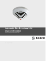
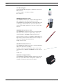
Automatic Fire Detectors LSN
improved version
FAP-DO420/FAP-420/FAH-420
en
Product Information
Automatic Fire Detectors LSN improved
version
Table of Contents | en
3
Table of Contents
1
Product Description
5
2
System Overview
6
2.1
Detector Configuration
6
2.2
Functional Description of the Sensor Technology
6
2.2.1
Optical Sensor (Smoke Detector)
6
2.2.2
Thermal Sensor (Heat Detector)
6
2.2.3
Chemical Sensor (Gas Sensor)
6
2.3
System Description
7
2.4
Flash Frequency and Error Detection
7
2.5
Features
7
3
Planning
9
3.1
Basic Installation/Configuration Notes
9
3.2
Use in a Local Security Network (LSN/LSN improved version)
9
3.3
Use in Areas with Elevated Radioactivity
9
4
Programming
10
4.1
FAP-DOTC420 / FAP-OTC 420
11
4.2
FAP-DOT420 / FAP-OT 420
12
4.3
FAP-DO420 / FAP-O 420 / FAP-O 420-KKW
12
4.4
FAH-T 420/FAH-T 420-KKW
13
5
Connection
14
5.1
Overview of Detector Bases
14
5.2
Installing the Base
15
5.3
Connection
16
5.3.1
Connecting the MS 400/MSF 400
16
5.3.2
Connecting the FAA-MSR 420
17
5.4
Detector Base Sounders
18
5.5
Installation of the Detector Module
19
5.6
Detector Removal
19
5.7
Addressing
20
6
Accessories
21
6.1
Support Plate for Detector Identification
21
6.2
SK 400 Protective Basket
21
6.3
SSK 400 Protective Dust Cover
21
6.4
MK 400 Detector Console
22
6.5
MH 400 Detector Heating Element
22
6.6
External Detector Alarm Displays/Remote Indicators
22
6.6.1
Installation Note for FAA-420-RI Remote Indicator
22
6.6.2
MPA External Detector Alarm Display
24
6.7
Service and Detector Test Accessories
26
Bosch Sicherheitssysteme GmbH
Product Information
F.01U.003.449 | 7.2 | 2010.05
4
Automatic Fire Detectors LSN improved
version
en | Table of Contents
7
Order Information
28
7.1
Detector Variants
28
7.2
Detector Bases
28
7.3
Detector Accessories
28
7.4
Installation Accessories
29
7.5
Detector Base Sounders
29
7.6
Service accessories
29
8
Maintenance and Service
30
8.1
Notes for the Service
31
8.1.1
Display of Operating Data in WinPara
31
8.2
Detector Type Encoding
33
8.3
Test Instructions for LSN improved version Fire Detectors
33
8.3.1
Test Instructions for All Fire Detectors With Optical Sensor
33
8.3.2
Test Instructions for FAP-DOTC420 / FAP-DOT420 / FAP-OTC 420 / FAP-OT 420
33
8.4
Warranty
34
8.5
Repair
34
8.6
Disposal
34
8.7
Additional documentation
34
9
Technical Data
35
A
Abbreviations
38
F.01U.003.449 | 7.2 | 2010.05
Product Information
Bosch Sicherheitssysteme GmbH
Automatic Fire Detectors LSN improved
version
1
Product Description | en
5
Product Description
NOTICE!
This product information describes the entire product range for the FAP-420/FAH-420
Automatic Fire Detectors LSN improved version series.
Wherever the term DO detector is used in this document, this refers to the following
detectors: FAP-DO420, FAP-DOT420, FAP-DOTC420.
The FAP-420/FAH-420 Automatic Fire Detectors LSN improved version series is specially
designed for connection to the FPA-1200 and the FPA-5000 Modular Fire Panel. The fire
detector series combines standard detection procedures such as scattered light
measurement and temperature measurement with gas measuring technology at the highest
configuration level.
This method uses intelligent evaluation electronics (Intelligent Signal Processing - ISP) to
evaluate the signals from the smoke sensor, thermal sensor and gas sensor. Thus security
against deceptive alarms is increased significantly and detection time is reduced in
comparison to the fire detectors available on the market today.
Thanks to the higher information content of the multisensor detectors, the use of detectors is
possible in environments where simple smoke detectors cannot be used.
The detectors are available in the following configuration levels:
–
FAP-DOTC420: combined dual-optical, thermal and chemical smoke detector
–
FAP-OTC 420: combined optical, thermal and chemical smoke detector
–
FAP-DOT420: combined dual-optical and thermal smoke detector
–
FAP-OT 420: combined optical and thermal smoke detector
–
FAP-DO420: dual-optical smoke detector
–
FAP-O 420/FAP-O 420 KKW: optical smoke detector
–
FAH-T 420/FAH-T 420 KKW: thermal detector
The line technology variants are:
–
LSN classic (classic Local Security Network)
–
LSN improved version (Local Security Network improved version)
The detector's timeless and innovative design is a result of the cooperation between
engineers and designers. With this design it is possible to reconcile the contradictory goals of
a generous installation space and a small detector.
The placement of the dual-color individual display on the detector tip is the first externally
visible characteristic of the installation-friendly development concept. The stable and robust
detector base need no longer be aligned due to the position-independent position of the
individual display.
It is suitable for surface and flush mounting and includes separate mounting points for
dropped ceiling and concealed sockets. In addition, it fits all common bore patterns. For
surface mounting, the cable may be fed through on the side.
The integrated strain relief for interfloor cables prevents the removal of cables from the
terminal after installation. The terminals are easily accessible; a retainer for the end of line
resistor is integrated. Cable diameters of up to 2.5 mm2 can be used.
It can be equipped with a damp room seal so that all installation requirements can be covered
with one base.
Bosch Sicherheitssysteme GmbH
Product Information
F.01U.003.449 | 7.2 | 2010.05
6
Automatic Fire Detectors LSN improved
version
en | System Overview
2
System Overview
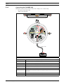
2.1
Detector Configuration
1
Smoke measurement chamber with
3
4
optical sensor
2
Thermal sensor
3
Chemical sensor (covered on the cross-
2
section)
1
4
Individual display
5
PC board with evaluation electronics
6
MS 400 Detector Base
6
5
Figure 2.1 Detector Configuration
2.2
Functional Description of the Sensor Technology
2.2.1
Optical Sensor (Smoke Detector)
This optical sensor utilizes the scattered-light method.
An LED sends light into the measuring chamber (see Figure 2.1, item 1), where it is absorbed
by the labyrinth structure. In the event of a fire, smoke enters the measuring chamber. The
light is scattered by the smoke particles and hits the photo diodes, which transform the
quantity of light into a proportional electrical signal.
The DO detectors have a dual optical sensor that uses the different infrared and blue light
wavelengths (Dual Ray technology). This allows fires to be detected early and even the
smallest quantities of smoke (TF1) to be reliably detected.
2.2.2
Thermal Sensor (Heat Detector)
A thermistor (see Figure 2.1, item 2) in a resistance network is used as a thermal sensor; an
analog-digital converter measures the temperature-dependent voltage at regular intervals.
Depending on the specified detector class, the thermal sensor triggers the alarm status when
the maximum temperature of 54 °C or 69 °C is exceeded (thermal maximum), or if the
temperature rises by a defined amount within a specified time (thermal differential).
2.2.3
Chemical Sensor (Gas Sensor)
The gas sensor (see Figure 2.1, item 3) detects mainly the
carbon monoxide (CO) that is produced by a fire, but it also
detects hydrogen (H) and nitrogen monoxide (NO).
The underlying measurement principle is CO oxidation and
the measurable current that it creates. The sensor signal
value is proportional to the concentration of gas.
The gas sensor supplies additional information in order to
3
reliably suppress disturbance variables.
Figure 2.2 Chemical sensor
F.01U.003.449 | 7.2 | 2010.05
Product Information
Bosch Sicherheitssysteme GmbH
Automatic Fire Detectors LSN improved
version
2.3
System Overview | en
7
System Description
Up to three detection principles are integrated in FAP-420/FAH-420 series detectors:
–
Optical (for smoke): O
–
Dual-optical (for smoke): DO
–
Thermal (for heat): T
–
Chemical (for gas): C
The individual sensors are programmed via the LSN network manually or using a timer. All
sensor signals are analyzed continually by the internal signal analysis electronics (ISP) and are
linked with each other. By linking the sensors (combined detectors), the detector can also be
used in places where the work carried out gives rise to light smoke, steam or dust. If a signal
combination fits the selected identifier for the area of operation for the detectors, an alarm is
triggered automatically.
2.4
Flash Frequency and Error Detection
The LSN improved detector has two centrally positioned two-color LEDs that flash green to
display the operational status.
The green LED on LSN improved FAP-420/FAH-420 series detectors is deactivated when
delivered. It can be activated as required via the programming software.
The LSN improved detector permanently monitors and adjusts itself throughout its life cycle
in order to adapt its sensitivity to the set threshold value.
A message is sent to the fire panel if the detector becomes too contaminated.
The LED will start to flash red as soon as an alarm is triggered.
The detector will return to its normal operating condition when the alarm is canceled via the
control panel or if the alarm cause disappears.
2.5
Features
–
Active self-monitoring of the sensors, with display on the fire panel:
–
Active adjustment of the threshold (drift compensation) if the optical sensor
becomes contaminated.
–
–
Active adjustment of the threshold (drift compensation) of the chemical sensor.
EMC safety is 50 V/m in the 1-3000 MHz range and is therefore much higher than
required by VdS 2110 (VdS Schadenverhütung GmbH). (Except DO detectors.)
–
Preservation of LSN loop functions in the event of wire break or short-circuit of a
detector through integrated isolators.
–
Individual detector identification on the fire panel in the event of an alarm. Alarm
indication on the detector with a flashing red LED.
–
–
Programmable, i.e. can be adjusted to the area of operation.
Increased detection and false alarm security thanks to evaluation of the temporal
behavior of fire and disturbance variables.
–
Activation of a remote indicator is possible.
–
Optional mechanical removal safeguard (can be activated/deactivated).
–
Dust-resistant labyrinth and cap construction.
–
Every detector base has a Chamber Maid Plug (a cleaning opening with a plug) for
blowing out the optical chamber with compressed air (not required for the FAH-T 420
Heat Detector).
–
For connecting to the FPA-5000 and FPA-1200 fire panels with extended range of LSN
features.
Bosch Sicherheitssysteme GmbH
Product Information
F.01U.003.449 | 7.2 | 2010.05
8
Automatic Fire Detectors LSN improved
version
en | System Overview
–
You can only use DO detectors with the MPC-xxxx-B Panel Controller or the FPA-1200.
The MPC-xxxx-A Panel Controller cannot be used.
–
In classic mode, can be connected to the BZ 500 LSN, UEZ 2000 LSN and UGM 2020 LSN
fire panels and to other panels or their receiver modules with identical connection
properties but with the existing LSN system limits. (Not DO detectors.)
–
It is possible to read out the serial number, contamination level (for the O sensor),
operating hours and current analog values for each configured detector (except for KKW
types) via LSN.
–
The DO detectors are not supported by the WinPara software.
–
Use of shielded and unshielded cables.
–
The LSN improved version line technology supports the connection of up to 254
FAP-420/FAH-420 series detectors per loop or stub (please observe national regulations
in this regard).
–
Flexible network structures without additional elements ("T-Tapping") are possible.
–
Automatic or manual detector addressing selectable.
–
Compliant with EN 54, EN 50131 and VdS guidelines.
F.01U.003.449 | 7.2 | 2010.05
Product Information
Bosch Sicherheitssysteme GmbH
Automatic Fire Detectors LSN improved
version
3
Planning | en
9
Planning
NOTICE!
FAP-420/FAH-420 Automatic Fire Detectors are not designed for exterior use.
3.1
Basic Installation/Configuration Notes
–
Multi-sensor fire detectors must be planned in line with the guidelines for optical
detectors until a guideline for their planning is developed in collaboration with the VdS
(see also DIN VDE 0833 Part 2 and VDS 2095):
–
–
Maximum monitoring area 120 m2.
–
Maximum installation height 16 m.
If occasional switch-off of the optical sensor is required, the planning must occur
according to the guidelines for heat detectors (see DIN VDE 0833 Part 2 and VDS 2095):
–
Maximum monitoring area 40 m2.
–
Maximum installation height 7.5 m.
–
Maximum permissible air speed: 20 m/s.
–
FAH-T 420 detectors must be configured according to Class A1R when planning fire
barriers conforming to DIBt.
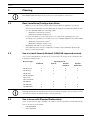
3.2
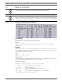
Use in a Local Security Network (LSN/LSN improved version)
In a Local Security Network, the detectors connected to a fire panel can be operated in the
following operating modes:
Detector Type
Operating mode
Combined
Optical
Thermal
Thermal
maximum
differential
FAP-OTC 420
X
X
X
X
FAP-OT 420
X
X
X
X
FAP-O 420/
-
X
-
-
-
-
X
X
FAP-DO420
-
X
-
-
FAP-DOT420
X
X
X
X
FAP-DOTC420
X
X
X
X
FAP-O 420 KKW
FAH-T 420/
FAH-T 420 KKW
NOTICE!
Planning should take the anticipated total current and line resistance into account to ensure
each detector has an operating voltage of at least 15 V DC.
3.3
Use in Areas with Elevated Radioactivity
There are two detector types available especially for use in areas with elevated radioactivity,
such as in nuclear power plants:
–
FAP-O 420-KKW
–
FAH-T 420-KKW
Bosch Sicherheitssysteme GmbH
Product Information
F.01U.003.449 | 7.2 | 2010.05
10
4
Automatic Fire Detectors LSN improved
version
en | Programming
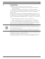
Programming
Programming occurs via a PC or laptop connected to the fire panel
–
With FSP-5000-RPS (Remote Programming System) for panels with LSN improved
version line technology
–
With WinPara for panels with conventional LSN line technology (not DO-Melder).
420 series detectors are programmed by entering the area of operation. The selection of the
area of operation determines the optimum characteristic field for fire and disturbance
variable evaluation.
When optical sensor sensitivity in the FAP-OTC 420 and FAP-DOTC420 is low, the detector
only triggers if both smoke and an increase in CO concentration or temperature is detected.
The operating mode can be changed for the FAP-OTC 420 and FAP-OT 420 detector models,
as well as the FAP-DOTC420 and FAP-DOT420 models, i.e. individual sensors can be switched
off:
–
Switch to optical (O sensor sensitivity = low, T sensor = switched off)
–
Switch to thermal differential (T sensor sensitivity = A2R, O sensor = switched off)
–
Switch to thermal maximum (T sensor sensitivity = A2S, O sensor = switched off).
In the case of the purely optical FAP-O 420 and FAP-DO420 detectors, the sensitivity of the
optical sensor can be set to three levels. Depending on the operating location, the optical
sensor in the detector is thus adjusted to the environmental conditions.
NOTICE!
For fire detection, the purely optical detector also evaluates the time behavior of the fire
characteristics, which differs significantly from the time behavior of disturbance variables and
that occurring during a detector test
As a result, there are also different trigger times when testing with a test aerosol outside of
Walk test operation (10 s to max 60 s), depending on the selected sensitivity adjustment.
The FAH-T 420 Heat Detector is programmed by taking into account the ambient temperature,
the installation height and the sensitivity class selection.
Programming of the optical, thermal, and chemical sensors and the linking of all sensors via
algorithms significantly increases the detection ability and security against false alarms.
F.01U.003.449 | 7.2 | 2010.05
Product Information
Bosch Sicherheitssysteme GmbH
Automatic Fire Detectors LSN improved
version
4.1
Programming | en
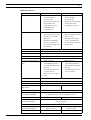
11
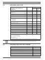
FAP-DOTC420 / FAP-OTC 420
Selectable installation locations in
Detector Type
Sensitivity
the programming software (WinPara
Thermom
Optical
Chemical
and FSP-5000-RPS)
ax (Tmax)
(O)
(C)
Office (after hours)
O, Tmax, Tdiff, C
High (A2)
High
High
Office (smoker)/waiting room/
O, Tmax, Tdiff, C
High (A2)
Low*
Low
Office (day mode)
O, Tmax, Tdiff, C
Low (B)
Medium
High
EDP room
O, Tmax, Tdiff, C
High (A2)
High
High
Production location
O, Tmax, Tdiff, C
Low (B)
Low*
Medium
Garage
O, Tmax, Tdiff, C
High (A2)
Low*
Low
High storage warehouse without
O, Tmax, Tdiff, C
Low (B)
High
High
O, Tmax, Tdiff, C
High (A2)
Low*
Medium
O, Tmax, C
Low (B)
Low*
Low
O, Tmax, Tdiff, C
Low (B)
Low*
Low
Tmax, Tdiff
High (A2)
-
-
O
-
Low
-
Tmax
High (A2)
-
-
O, C
-
Low
High
Schools/kindergarten
O, Tmax, Tdiff, C
High (A2)
Medium
High
Theater/concert hall
O, Tmax, Tdiff, C
High (A2)
Medium
High
restaurant/meeting room
vehicle traffic with combustion
engine
Conference hall/waiting room/
fairground
Kitchen/casino/restaurant during
active operation
Warehouse with vehicle traffic
Rate of rise only (optical sensor off)**
Optical only (thermal sensor off)**,
***
Fixed temperature heat only (optical
sensor off)**
Optical/chemical (thermal sensor
off)**, ***
O = optical sensor (dual-optical in FAP-DOTC420 detectors)
Tmax = thermal maximum unit
Tdiff = thermal differential unit
C = chemical sensor
* If optical sensor sensitivity is low, the detector will only trigger if smoke as well as an
increase in CO concentration or temperature is detected.
** FSP-5000-RPS only
*** For FAP-DOTC420: does not comply with EN54-7
For details on installation height, see Section 4.4 FAH-T 420/FAH-T 420-KKW, page 13
NOTICE!
The FAP-DOTC420 detector is not supported by the WinPara programming software.
Bosch Sicherheitssysteme GmbH
Product Information
F.01U.003.449 | 7.2 | 2010.05
12
4.2
Automatic Fire Detectors LSN improved
version
en | Programming
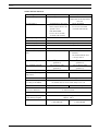
FAP-DOT420 / FAP-OT 420
Selectable installation locations in the
Detector Type
Sensitivity
programming software (WinPara and
Thermomax
FSP-5000-RPS)
(Tmax)
Optical
(O)
Office (after hours)
O, Tmax, Tdiff
High (A2)
High
Office (smoker)/waiting room/restaurant/
O, Tmax, Tdiff
High (A2)
Low
Office (day mode)
O, Tmax, Tdiff
Low (B)
Medium
EDP room
O, Tmax, Tdiff
High (A2)
High
Production location
O, Tmax, Tdiff
Low (B)
Low
meeting room
Garage
–
FAP-OT 420
Tmax, Tdiff
High (A2)
-
–
FAP-DOT420
Tmax, Tdiff
High (A2)
Low
O, Tmax, Tdiff
Low (B)
High
O, Tmax, Tdiff
High (A2)
Low
Tmax
Low (B)
-
O, Tmax, Tdiff
Low (B)
Low
Tmax, Tdiff
High (A2)
-
O
-
Low
Tmax
High (A2)
-
Schools/kindergarten
O, Tmax, Tdiff
High (A2)
Medium
Theatre/concert hall
O, Tmax, Tdiff
High (A2)
Medium
High storage warehouse without vehicle traffic
with combustion engine
Conference hall/waiting room/fairground
Kitchen/casino/restaurant during active operation
Warehouse with vehicle traffic
Rate of rise only (optical sensor off)**
Optical only (thermal sensor off)**
Fixed temperature heat only (optical sensor off)**
O = optical sensor (dual-optical in FAP-DOT420 detectors)
Tmax = thermal maximum unit
Tdiff = thermal differential unit
** FSP-5000-RPS only
For details on installation height, see Section 4.4 FAH-T 420/FAH-T 420-KKW, page 13
NOTICE!
The FAP-DOT420 detector is not supported by the WinPara programming software.
4.3
FAP-DO420 / FAP-O 420 / FAP-O 420-KKW
Installation locations
Selectable sensitivity
Theater/concert hall
Medium
Warehouse with vehicle traffic
Low
Office (smoker)/waiting room/restaurant/meeting room
Low
Conference hall/waiting room/fairground
Low
Office (after hours)
High
School/kindergarten
Medium
Production location
Low
F.01U.003.449 | 7.2 | 2010.05
Product Information
Bosch Sicherheitssysteme GmbH
Automatic Fire Detectors LSN improved
version
Programming | en
Installation locations
13
Selectable sensitivity
EDP room
High
High storage warehouse without vehicle traffic with combustion
High
engine
Office (day mode)
4.4
Medium
FAH-T 420/FAH-T 420-KKW
Selectable installation locations in the programming software (WinPara and
FSP-5000-RPS)
§ A2R
Typical application temperature: 25 °C, Tmax + Tdiff, height up to 6 m
A2S
Typical application temperature: 25 °C, only Tmax, height up to 6 m
A1R
Typical application temperature: 25 °C, Tmax + Tdiff, height 6 m to 7.5 m
A1
Typical application temperature: 25 °C, only Tmax, height 6 m to 7.5 m
BR
Typical application temperature: 40 °C, Tmax + Tdiff, height up to 6 m
BS
Typical application temperature: 40 °C, only Tmax, height up to 6 m
§ = Basic setting in the WinPara and FSP-5000-RPS programming software
Sensitivity classes as per EN 54 Part 5
With the detector types FAH-T 420 and FAH-T 420-KKW, it is possible to set one of the
sensitivity classes listed above in line with planning.
In the sensitivity classes A1, A2S and BS, the FAH-T 420 or FAH-T 420-KKW is operated purely
as a thermal maximum detector. In this case, the detector does not activate at below 54 °C in
class A2S, and not below 69 °C in class BS.
The sensitivity classes A2S and BS are therefore particularly suitable for applications where
higher temperature rates-of-rise occur over a longer period, e.g. in kitchens or boiler rooms.
The sensitivity classes A1R, A2R and BR indicate that the thermal differential unit is active in
addition to the thermal maximum unit.
These sensitivity classes are especially well-suited for use in unheated buildings where the
ambient temperature can vary greatly but high temperature rates-of-rise do not last long.
The thermal differential unit enables class A1R/A2R detectors to respond at T<54 °C and class
BR detectors at T<69 °C.
The selection of the sensitivity class also depends on the installation height of the detector.
To maintain the greatest possible security against false alarms, classes A1 and A1R should not
be selected for room heights below 6 m, although these classes are in theory permitted.
Furthermore, the expected application temperature must be taken into consideration.
Temperature
Response time for detectors in the
Response time for detectors in the
rate-of-rise [K
sensitivity class A1R
sensitivity classes A2R/BR
min-1]
Lower limiting
value [min/sec]
Upper limiting
Lower limiting
Upper limiting
value [min/sec]
value [min/sec]
value [min/sec]
10
1 min
4 min 20 s
2 min
5 min 30 s
20
30 s
2 min 20 s
1 min
3 min 13 s
30
20 s
1 min 40 s
40 s
2 min 25 s
Bosch Sicherheitssysteme GmbH
Product Information
F.01U.003.449 | 7.2 | 2010.05
14
Automatic Fire Detectors LSN improved
version
en | Connection
5
Connection
5.1
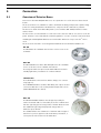
Overview of Detector Bases
Detectors in the FAP-420/FAH-420 series are operated in one of the detector bases listed
below.
The detector bases are suitable for surface and flush mounting, and provide separate fixing
points for ceiling and flush mount back boxes. They also fit all common bore patterns.
The bases are made from white ABS plastic (color similar to RAL 9010) and have a matte
surface finish.
The bases have screw terminals for connection of the detector and its accessories to the fire
panel. Contacts connected with the terminals guarantee a secure electrical connection when
installing the FAP-420/FAH-420 Detector Head. Cable diameters of up to 2.5 mm2 can be
used.
The detector head can be secured against unauthorized removal with a variable lock.
MS 400
The MS 400 is the standard detector base. It has seven screw
terminals.
MSF 400
The MSF 400 Detector Base with Damp Room Seal is available
for use of the detector in a humid environment.
The integrated TPE seal protects the MSF 400 Detector Base
reliably against the penetration of condensed water.
FAA-MSR 420
The FAA-420-R is a detector base with a change-over contact
relay (type C).
The FAA-MSR 420 Detector Base with Relay can only be used in
connection with the Local Security Network improved version
(FPA-5000 Modular Fire Panel).
MSC 420
The MSC 420 Additional Base was designed specially for
surface-mounted cable feed via cable protection conduits and
has two opposing pre-cut entry points of 20 mm diameter and
two additional opposing and prepared entry points for
diameters up to 28 mm.
The additional base has a diameter of 120 mm and a height of
36.7 mm. To protect against condensed water penetration, a
seal is placed on the bottom of the MSC 420.
F.01U.003.449 | 7.2 | 2010.05
Product Information
Bosch Sicherheitssysteme GmbH
Automatic Fire Detectors LSN improved
version
5.2
Connection | en
15
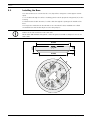
Installing the Base
The detector bases are screwed to the even, dry surface using two screws approx. 55 mm
apart.
To feed cables through for surface mounting, punch out the prepared entry points (X) on the
housing.
For flush-mounted cable insertion, feed the cable through the opening in the middle of the
base.
The long holes marked in the sketch with "Y" are intended for base installation in a flush
mount back box and should only be used for this purpose.
NOTICE!
Cables can be fed in and out on the same side.
On the MSF 400 and MSC 420, punch out the integrated seal with a sharp tool. Do not cut
with a knife.
Ø 120
14
7.8
22.7
X
Ø 100
55
Y
Y
Bosch Sicherheitssysteme GmbH
Product Information
F.01U.003.449 | 7.2 | 2010.05
16
Automatic Fire Detectors LSN improved
version
en | Connection
5.3
Connection
NOTICE!
Keep shield wire as short as possible and insulate.
5.3.1
Connecting the MS 400/MSF 400
4
3
1
1
2
5
max. 3 m
MPA /
FAA-420-RI
Key
1
Yellow, connection to b1/b2 (LSN +)
2
White, connection to a1/a2 (LSN -)
3
Red, connection to +V
4
Black, connection to 0 V
5
Green, connection to shielding wire
c
Indicator output
+V/0 V
Terminals for looping through the supply voltage for downstream
elements
EOL
Line termination (end-of-line module)
MPA/FAA-420-RI
Remote indicator
F.01U.003.449 | 7.2 | 2010.05
Product Information
Bosch Sicherheitssysteme GmbH
Automatic Fire Detectors LSN improved
version
5.3.2
Connection | en
17
Connecting the FAA-MSR 420
Maximum contact load (resistive load) of the change-over contact relay:
–
62.5 VA: 0.5 A at 125 V AC
–
30 W: 1 A at 30 V DC
NC
C
NO
1
1
2
3
4
5
c
max. 3 m
MPA /
FAA-420-RI
Key
1
Yellow, connection to b1/b2 (LSN +)
2
White, connection to a1/a2 (LSN -)
3
MPA/FAA-420-RI: Red, connection to b1
4
MPA/FAA-420-RI: Black, connection to c (indicator output)
5
Green, connection to shield wire
NC/C/NO
Change-over contact relay
+V/0 V
Terminals for looping through the supply voltage for downstream
elements
EOL
Line termination (end-of-line module)
MPA/FAA-420-RI
remote indicator
Bosch Sicherheitssysteme GmbH
Product Information
F.01U.003.449 | 7.2 | 2010.05
18
5.4
Automatic Fire Detectors LSN improved
version
en | Connection
Detector Base Sounders
Detector base sounders are used if acoustic alarm signaling is required directly at the fire
source. Detector base sounders are available in four variants.
–
MSS 300 Detector Base Sounder White, for
conventional line technology, activation via the C point
of the detector in use.
–
MSS 300 WS-EC Detector Base Sounder White, for
conventional line technology, with external activation
(via an interface module).
–
FNM-420-A-BS Detector Base Sounder White or Red, for
LSN line technology, with power supply via the LSN
with 32 different tones.
–
MSS 401 Detector Base Sounder White, for LSN line
technology, with separate power supply.
The integrated tone generator has 11 tones for selection
(incl. tones conforming to DIN 33404 and EN 457) with
sound pressure of max. 100 dBA, depending on the type of
tone selected.
With the LSN variants, the volume (4 levels) and also the
tone type are programmed via the fire panel. The tone type
on conventional variants is set via four DIP switches and the
volume is adjusted continuously via a potentiometer.
F.01U.003.449 | 7.2 | 2010.05
Product Information
Bosch Sicherheitssysteme GmbH
Automatic Fire Detectors LSN improved
version
5.5
Connection | en
19
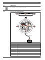
Installation of the Detector Module
NOTICE!
The packaging for the multisensor detector with C sensor consists of tear-proof PE-ALU
laminated film and must be cut open carefully.
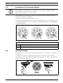
After installation and connection of the base, the detector head is set into the base and
turned to the right as far as it will go.
Detector bases are delivered with inactive locks.
The detector module can be locked in the base (removal protection). The locking feature is
activated by breaking the bolt (X) out of the base and pushing it into the corresponding guide,
as shown in Figure 5.1.
1
2
3
X
X
X
X
Figure 5.1 Activation of the removal protection mechanism
Key
5.6
1
Bolt (X) before breaking out
2
Bolt (X) fitted, but deactivated
3
Locking activated
Detector Removal
Unlocked detector heads are disassembled by turning them to the left and removing them
from the base.
Locked detector heads are disassembled by inserting a screwdriver into the unlocking
opening (Y) so that the bolt is pushed upward; at the same time, the detector head should be
turned to the left (see Figure 5.2).
Y
Figure 5.2 Detector removal (locked detector module)
Bosch Sicherheitssysteme GmbH
Product Information
F.01U.003.449 | 7.2 | 2010.05
20
5.7
Automatic Fire Detectors LSN improved
version
en | Connection
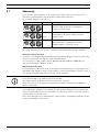
Addressing
There are three rotary switches on the bottom of the detector; these are used to select
automatic or manual address allocation with or without auto-detection.
The following settings are possible:
Rotary switch setting
Address
000
Operating mode
Loop/stub with LSN improved version mode and
automatic address allocation (T-tapping not
possible) = delivery status
001
Loop/stub/T-tapping with LSN improved mode and
...
manual address allocation (address shown in
245
example = 131)
CL 0 0
Loop/stub in classic LSN mode with automatic
address allocation (T-tapping not possible,
maximum number of elements = 127)
The rotary switches are moved to the required position using a slotted-head screwdriver.
Automatic address allocation
If addresses are automatically allocated by a fire panel with LSN improved version technology,
all detectors must have the address "0 0 0" (delivery status).
For connection to classic LSN fire panels (BZ 500 LSN, UEZ 2000 LSN, UGM 2020), all
detectors must have the address "CL 0 0".
Manual address allocation
For manual address allocation, the detector address is set with the three rotary switches. The
right-hand rotary switch is used to set the units, the central rotary switch is used to set the
tens and the left-hand rotary switch is used to set the hundreds.
NOTICE!
It is not permissible to use addresses greater than 254.
This will prompt the display of an error message on the fire panel.
All the detectors in a loop, stub or T-tap must have an address between 1 and 254 when
addressed manually.
From LSN module software version 1.0.35, you can operate LSN improved version and LSN
classic elements together in one loop or stub. If an LSN classic element is present, only 127
elements can be used in the loop.
Please note that only loop or stub structures can be used for configurations with mixed LSN
classic and LSN improved elements.
F.01U.003.449 | 7.2 | 2010.05
Product Information
Bosch Sicherheitssysteme GmbH
Automatic Fire Detectors LSN improved
version
Accessories | en
6
Accessories
6.1
Support Plate for Detector Identification
21
The support plates are made from 1.8 mm thick ABS plastic and are clamped between the
detector base and the ceiling.
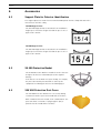
TP4 400 Support Plate
The TP4 400 Support Plate is intended for an installation
height up to 4 m and is designed for labels up to a size of
approx. 65 x 34 mm.
15 / 4
TP8 400 Support Plate
The TP8 400 Support Plate is intended for an installation
height up to 8 m and is designed for labels up to a size of
approx. 97 x 44 mm.
6.2
SK 400 Protective Basket
The SK 400 Protective Basket is installed over the detector
and gives the detector substantial protection against
damage.
If the detector is mounted in a sports facility, for example,
the protective basket prevents balls or other sports
equipment from hitting the detector and damaging it.
6.3
SSK 400 Protective Dust Cover
The SSK 400 Protective Dust Cover is necessary during
construction work to protect an installed detector base,
with or without detector module, from contamination. The
protective dust cover made of polypropylene (PP) is
pushed onto the installed detector base.
Bosch Sicherheitssysteme GmbH
Product Information
F.01U.003.449 | 7.2 | 2010.05
22
Automatic Fire Detectors LSN improved
version
en | Accessories
6.4
MK 400 Detector Console
The MK 400 Detector Console is used to install detectors
above door frames or similar in compliance with DIBt.
The console is supplied with a pre-mounted MS 400
Detector Base (the detector shown is not included in the
scope of delivery).
6.5
MH 400 Detector Heating Element
The MH 400 Detector Heating Element is required if the detector is used in an environment
where water condensation can occur, such as in a warehouse that must frequently be opened
briefly for delivery vehicles.
The detector heating element is connected to the + V/0 V terminals in the detector base.
Operating voltage: 24 V DC
Resistance: 1 kΩ
Power consumption: 3 W.
The heating is supplied with power either by the fed-through supply voltage via the central
unit or by a separate power pack.
With supply via the central unit, the number of detector heating elements depends on the
cable diameter and line length used.
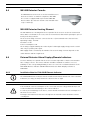
6.6
External Detector Alarm Displays/Remote Indicators
A remote indicator is required if the detector is not directly visible or has been mounted in
false ceilings or floors. The remote indicator should be installed in corridors or access
pathways to the corresponding building sections or rooms. The red alarm indication of the
FAA-420-RI Remote Indicator and MPA External Detector Alarm Display conforms to
DIN 14623.
6.6.1
Installation Note for FAA-420-RI Remote Indicator
NOTICE!
The FAA-420-RI Remote Indicator must be installed such that the broad side of the red alarm
indication (see image, item B) follows the observer's line of sight.
WARNING!
If the maximum current consumption of the connected detector is larger than 20 mA, it can
result in malfunctions and damage to the remote indicator.
In order to prevent damage to the device, ensure that the maximum current consumption of
20 mA is not exceeded.
Point-type automatic Bosch detectors already have an internal resistor that limits current
consumption.
F.01U.003.449 | 7.2 | 2010.05
Product Information
Bosch Sicherheitssysteme GmbH
Automatic Fire Detectors LSN improved
version
Accessories | en
23
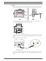
Installation
1.
Before assembly, remove the cap from the base plate: To unlock the snap-fit hooks (see
image, item C) with a flat object (e.g. screwdriver), press in and lift the cap carefully.
35 mm
80 mm
80 mm
A
B
D
C
b
a
2.
Fit the FAA-420-RI directly to the ceiling or wall. To do this, secure the base plate to a
level, dry surface with two (item E) or four (item F) screws.
57 mm
57 mm
E
__++
F
G
3.
Punch out the pre-punched cable entries (item D) to insert cables for surface mounting.
For flush mounting, insert cables through the opening (item G) under the connection
board.
4.
Connect the FAA-420-RI via two terminals.
C
b1/+V
_ +
FAA-420-RI
5.
Place the cap on the base plate in such a way that the two hooks (item A) are inserted
into the slits. Press the cap lightly onto the base plate until the snap-fit hook (item C)
engages.
Bosch Sicherheitssysteme GmbH
Product Information
F.01U.003.449 | 7.2 | 2010.05
24
Automatic Fire Detectors LSN improved
version
en | Accessories
Technical data
6.6.2
Operating voltage
5–30 V DC
Weight
45 g
Display medium
2 LEDs
Permissible wire gauge
0.6–2 mm
Maximum current consumption
20 mA
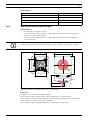
MPA External Detector Alarm Display
Installation note
–
Fitted directly to the wall or ceiling.
–
To feed cables through for surface mounting, punch out the prepared entry points (see
Figure 6.1, item X) on the housing.
–
For flush-mounted cable insertion, feed the cable through the opening beneath the
connection board.
NOTICE!
The flat side of the prism (see Figure 6.1, item Y) must follow the observer's line of sight.
85
60
85
55
A
1234
Y
39
55
X
11
A
Y
Figure 6.1 Installation of the MPA External Detector Alarm Display
Connection
The MPA is connected via four Wago terminals.
Connecting: Insert the stripped cable end (no braided wire) into the terminal.
Disconnecting: Turn wire alternately to the left and right, thus pulling it out of the terminal.
Up to 4 detectors can be connected to each MPA.
Three inputs (terminals 2-4) allow adjustment to various line technologies.
F.01U.003.449 | 7.2 | 2010.05
Product Information
Bosch Sicherheitssysteme GmbH
Automatic Fire Detectors LSN improved
version
Accessories | en
25
Connection depending on the line technology
Line technology
Fire panel
Terminals
Conventional
BZ 1060
1+2
Conventional
FPA-5000, UEZ 1000, UGM 2020, FP 102/104/106
1+3
LSN
FPA-5000, FPA-1200, BZ 500 LSN, UEZ 1000,
1+4
UEZ 2000 LSN, UGM 2020
Terminal
Connection
1
Ground
2
Entry point flashing (LED flashes)
3
Entry point static (LED flashes)
4
Entry point static (LED flashes)
A resistor is necessary to connect to terminal 4; otherwise, the LED
1234
may be damaged.
All current Bosch detectors are equipped with an internal resistor to
restrict current consumption.
CAUTION!
If the current consumption for the connected detector exceeds 20 mA, it can lead to the
malfunction of or damage to the MPA.
You should restrict the maximum detector current consumption to 20 mA to avoid damaging
the MPA.
NOTICE!
The cable length between the detector and the MPA must not exceed 3 m when connected by
an unshielded cable.
MPA technical specifications
Operating voltage
9 V DC to 30 V DC
Maximum current consumption
–
Terminal 2
–
approx. 2 mA
–
Terminal 3
–
limited to approximately 13 mA
–
Terminal 4
–
limit to maximum 20 mA
Display medium
1 LED
Permissible wire gauge
0.6 mm. . . 0.8 mm
Dimensions
79 x 79 x 31 mm
Weight
Approx. 65 g
VdS approval number
G 294 052
Bosch Sicherheitssysteme GmbH
Product Information
F.01U.003.449 | 7.2 | 2010.05
26
6.7
Automatic Fire Detectors LSN improved
version
en | Accessories
Service and Detector Test Accessories
SOLO200 Detector Removal Tool
The pivoting grips and three different diameters make
the SOLO200 Detector Removal Tool suitable for
removing and replacing most fire detectors.
The plastic caps enable the fire detector to be securely
gripped and protect the detector surface against
damage.
RTL-cap plastic caps for the SOLO200 Detector
Removal Tool
Scope of delivery = 2 pieces
FME-420-ADAP Tool Adapter for MS 420
The FME-420-ADAP Tool Adapter can be used in addition
to the SOLO200 Detector Removal Tool. The plastic bowl
and the adapter pole optimize the insertion and removal
of fire detectors when using detector bases with springs
(MS 420, FAA-MS 420-R-SP).
Note: Only use the plastic bowl in conjunction with the
adapter pole. On the adapter pole there is a rubber
bearing that cushions the turning motion when removing
the fire detectors and prevents damage.
SOLO330 Smoke Detector Tester
The SOLO330 Smoke Detector Tester is used to test
smoke detectors on site. A testing gas that simulates
smoke particles is used to do this.
Solo A3-001 Test Aerosol for Optical Smoke Detectors
Spray can with 250 ml test aerosol for optical smoke
detectors
DU = 12 pieces
F.01U.003.449 | 7.2 | 2010.05
Product Information
Bosch Sicherheitssysteme GmbH
Automatic Fire Detectors LSN improved
version
Accessories | en
27
Solo CO testing gas
Spray can with CO testing gas for multisensor detectors
with C sensor.
Contents: approx. 4 l compressed gas
DU = 12 pieces
SOLO461 Heat Detector Tester
The SOLO461 Heat Detector Tester is battery-operated
and conducts hot air to the heat detector sensor.
The SOLO461 uses patented CAT™ technology (Cross Air
Technology), which bundles the air and feeds it to the
sensor horizontally, regardless of the size or form of the
detector.
SOLO100 Telescopic Access Pole
The SOLO100 Telescopic Access Pole is used to install
and replace fire detectors on high ceilings. It can be
extended by three SOLO101 Fixed Extension Poles.
The telescopic access pole is suitable for applications in
high-voltage environments and was tested at a voltage of
20 kV in line with BS EN 61235 Part 12.
Length: 1 m to 3.4 m
SOLO101 Fixed Extension Pole
The SOLO101 Fixed Extension Pole is used to install and
replace fire detectors on ceilings.
It can be used on its own, with up to three other fixed
extension poles or with the SOLO100 Telescopic Access
Pole.
Length: 1 m
SOLO610 Test Equipment Bag
The SOLO610 Test Equipment Bag is made from strongly
woven polyester with a PVC coating and is suitable for
carrying or storing test and service products.
Bosch Sicherheitssysteme GmbH
Product Information
F.01U.003.449 | 7.2 | 2010.05
28
Automatic Fire Detectors LSN improved
version
en | Order Information
7
Order Information
7.1
Detector Variants
Type number
Designation
Product ID
FAP-DOTC420
Dual-optical, thermal, chemical multisensor detector
F.01U.116.034
FAP-OTC 420
Optical, thermal, chemical multisensor detector
F.01U.508.816
FAP-DOT420
Dual-optical, thermal multisensor detector
F.01U.116.033
FAP-OT 420
Multisensor Detector Optical/Thermal
F.01U.508.815
FAP-DO420
Dual-optical smoke detector
F.01U.116.032
FAP-O 420
Optical Smoke Detector
F.01U.508.813
FAH-T 420
Heat Detector
F.01U.508.915
Optical smoke detector for use in areas with elevated
F.01U.508.687
FAP-O 420 KKW
radioactivity
FAH-T 420 KKW
Heat detector for use in areas with elevated
F.01U.508.686
radioactivity
7.2
Detector Bases
Type number
Designation
Product ID
MS 400
Standard detector base, for surface-mount and flush-
4.998.021.535
mount cable insertion
MSF 400
Detector base with damp room seal, for surface-
4.998.079.480
mount and flush-mount cable insertion
FAA-MSR 420
Detector Base with Relay
F.01U.508.658
MSC 420
Additional base with damp room seal, for surface-
4.998.113.025
mount cable insertion
7.3
Detector Accessories
Type number
TP4 400
Designation
Product ID
Support Plate for Detector Identification, installation
4.998.084.709
heights up to 4 m (1 pack = 50 pieces)
TP8 400
Support Plate for Detector Identification, installation
4.998.084.710
heights up to 8 m (1 pack = 50 pieces)
SK 400
Protective Basket to guard against mechanical
4.998.025.369
damage
SSK 400
Protective Dust Cover (1 pack= 10 pieces)
4.998.035.312
MH 400
Detector heating element
4.998.025.373
F.01U.003.449 | 7.2 | 2010.05
Product Information
Bosch Sicherheitssysteme GmbH
Automatic Fire Detectors LSN improved
version
7.4
Order Information | en
29
Installation Accessories
Type number
Designation
Product ID
MK 400
Detector Console, for DIBt-compliant detector
4.998.097.924
installation above doors or similar, incl. detector base
FMX-DET-MB
Mounting bracket, with installation material for false
2.799.271.257
floors, no detector base
7.5
Detector Base Sounders
Type number
Designation
Product ID
MSS 300
Detector Base Sounder White, conventional line
4.998.025.372
technology,
only C point activation via attached detector, for
surface-mount and flush-mount cable insertion
MSS 300 WS-EC
Detector Base Sounder White, conventional line
4.998.120.501
technology,
only for external activation, for surface-mount and
flush-mount cable insertion
FNM-420-A-BS-WH
Detector Base Sounder White, LSN, power supply via
F.01U.064.687
LSN,
C point activation via attached detector or external
activation via LSN, for surface-mount and flush-mount
cable insertion
MSS 401 LSN
Detector Base Sounder White, LSN, separate power
4.998.102.859
supply required,
C point activation via attached detector or external
activation via LSN, for surface-mount and flush-mount
cable insertion
7.6
Service accessories
Type number
Designation
Product ID
SOLO200
Detector Removal Tool
4.998.112.113
RTL-cap
Plastic caps for the SOLO200 Detector Removal Tool
4.998.082.502
(scope of delivery = 2 pieces)
FME-420-ADAP
Tool Adapter for MS 420
F.01U.510.318
SOLO330
Smoke Detector Tester
4.998.112.071
Solo A3-001
Test Aerosol for Optical Smoke Detectors
4.998.112.074
Solo CO Testing
Solo CO Testing gas (400 ml, 1 pack = 10 pieces)
4.998.109.056
SOLO461
Heat Detector Tester
4.998.112.072
SOLO720
Battery for SOLO461 Heat Detector Tester
4.998.147.576
SOLO100
Telescopic Access Pole
4.998.112.069
SOLO101
Fixed Extension Pole
4.998.112.070
SOLO610
Test Equipment Bag
4.998.112.073
gas
Bosch Sicherheitssysteme GmbH
Product Information
F.01U.003.449 | 7.2 | 2010.05
30
Automatic Fire Detectors LSN improved
version
en | Maintenance and Service
8
Maintenance and Service
In Germany, maintenance work and inspection work on security systems are governed by the
regulations of DIN VDE 0833; these regulations stipulate reference to the manufacturer’s
instructions for maintenance intervals.
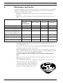
–
Maintenance and inspection work should be carried out regularly and by trained
personnel.
–
BOSCH ST recommends carrying out a functional and visual inspection at least once a
year.
Testing
Detector Type
FAP-DO420
FAH-T 420
FAP-DOT420
FAP-DOTC420
FAP-O 420
FAH-T 420 KKW
FAP-OT 420
FAP-OTC 420
FAP-O 420 KKW
Check of the LED display
X
X
X
X
Visual check of the mounting
X
X
X
X
Visual check for damage
X
X
X
X
Check the monitoring range has not
X
X
X
X
Triggering with hot air
-
X
X
X
Triggering with Solo A3-001 Test
X
-
X
X
-
-
-
X
been restricted, for instance by
shelves or similar installations.
Aerosol
Triggering with Solo CO Testing gas
–
FAP-OTC 420 / FAP-DOTC420
An FAP-OTC 420 will deactivate its C sensor after 5 years of operation due to the gas
sensor's limited life cycle.
On the panel, the detector in question is displayed with "EMERGENCY OPERATION" and
it continues to function as an OT or O detector.
With the FAP-DOTC420, the gas sensor has a life cycle of 6 years. Once the gas sensor
has been switched off, this detector continues to function as a DOT or DO detector and
is displayed on the panel with "EMERGENCY OPERATION".
This is why multisensor detectors with C sensors need to be exchanged every 5-6
years.
–
Optical fire detectors should, depending on the environmental conditions, be cleaned
and exchanged every 4-6 years.
In especially dusty environments, cleaning and exchange may be necessary earlier.
Every detector base has a Chamber Maid Plug
(cleaning opening with a plug) for blowing out
the optical chamber with compressed air (not
required for the FAH-T 420 Heat Detector).
F.01U.003.449 | 7.2 | 2010.05
Product Information
Bosch Sicherheitssysteme GmbH
Automatic Fire Detectors LSN improved
version
8.1
Maintenance and Service | en
31
Notes for the Service
NOTICE!
The DO detectors are not supported by the WinPara programming software.
NOTICE!
With the exception of the special KKW detector types, you can use the WinPara programming
software (V 4.53 or higher) to display the serial number, contamination level, operating hours
and current analog values for all configured detectors.
8.1.1
Display of Operating Data in WinPara
Module Address
Module where the detector or detector line is installed.
Address
Detector installation address, e.g. 10-03: The detector is in zone 10 and is the detector
number 3.
Brief Info
Additional information entered during programming. e.g. "FAP-O 420 on MSS400" means that
the FAP-O 420 is installed together with an MSS 400 Detector Base Sounder. You can also
enter the position of the detector here.
Type
display of the set detector type.
Serial number
The first digit of the 8-digit serial number represents the year of manufacture, i.e. a detector
with the serial number 3931859 was manufactured in 2003.
Current analog values
Optical system value (display of the current contamination value):
0 . . . 170
Initial set-up value for a new detector
0 . . . 350
Normal working range
350 . . . 450
Slight contamination: Exchange detector soon
450 . . . 510
Heavy contamination: Exchange detector immediately
From 511 O fault: optical sensor is deactivated!
Bosch Sicherheitssysteme GmbH
Product Information
F.01U.003.449 | 7.2 | 2010.05
32
Automatic Fire Detectors LSN improved
version
en | Maintenance and Service
Temperature value [°C] (display of the value currently being measured by the thermal
sensor):
FAH-T 420
-20 °C. . . +65 °C
FAP-OT 420
-20 °C. . . +50 °C
FAP-OT 420
-10 °C to +50 °C
CO value: Display of the value currently being measured by the CO sensor
The CO value specifies the currently-measured CO concentration.
The specified number is calculated as the difference between the current measurement value
and the stand-by value stored in the detector.
The CO concentration displayed lies in the range between 0 (normal operating condition)
and 555 (max. measurement value of the sensor).
Operating hours counter
Display of the duration of operation since the initial start-up of the detector.
Error code C malfunction
Error code
01000000
Cause of trouble and troubleshooting
General C malfunction
Possible causes:
–
–
Thermal sensor fault
Maximum operation duration (5 years) of the C sensor has been
exceeded.
T and C sensors are switched off; the optical sensor is still in operation.
Exchange detector immediately!
01100000
The impedance of the electrochemical cell is too high.
The C sensor is switched off; the rest of the sensors are still in operation.
Exchange detector immediately!
01010000
The permissible operating temperature (-10 °C to +50 °C) has been
exceeded. The C sensor is switched off; the rest of the sensors are still in
operation.
01001111
Malfunction due to read/write error in the EEPROM
Detector is switched off and must be exchanged immediately!
00000xxx
Number of read/write errors in the EEPROM
Contamination
The optical initial set-up value of a new detector is stored in the integrated EEPROM during
the final inspection. The contamination value specifies by how much this analog value has
increased in comparison with the delivery state.
F.01U.003.449 | 7.2 | 2010.05
Product Information
Bosch Sicherheitssysteme GmbH
Automatic Fire Detectors LSN improved
version
8.2
Maintenance and Service | en
33
Detector Type Encoding
With the exception of the FAP-O 420 and FAP-O 420-KKW, all detectors are fitted with a
colored ring around the central individual display to identify the detector type.
This facilitates inspection by service personnel.
8.3
Type number
Color code
FAP-DOTC420
2 x yellow
FAP-OTC 420
Yellow
FAP-DOT420
2 x black
FAP-OT 420
Black
FAH-T 420
Red
FAH-T 420-KKW
Red
FAP-DO420
2 x gray
FAP-O 420
-
FAP-O 420-KKW
-
Test Instructions for LSN improved version Fire Detectors
The latest generation of FAP-DOTC420 / FAP-OTC 420 Multisensor Detectors is equipped with
an additional sensor for detecting CO in the event of a fire. The CO sensor provides improved
response behavior and increased malfunction suppression in critical environmental
conditions.
For fire detection, detectors use the time behavior of the fire characteristics, which deviates
significantly from the time behavior of disturbance variables and also from the time behavior
of a detector check with aerosol.
Therefore, for a functional test, the detector must be switched to revision mode.
8.3.1
Test Instructions for All Fire Detectors With Optical Sensor
–
On the fire panel, switch the detector zone to be inspected to revision mode. Thus the
detector is set automatically into revision operation and prepared for the detector test.
–
Only in walktest mode can the detector’s individual sensors be made to trigger one after
the other with the corresponding test device. For this, you should use the service
accessories we recommend.
–
The optical sensor is tested with the detector tester for smoke detectors with the Solo
A3-001 Test Aerosol.
NOTICE!
The test head must remain over the detector until the detector has been triggered. The
distribution of the test aerosol in the transceiver and thus the trigger time of the sensor can
take up to 10 seconds.
8.3.2
Test Instructions for FAP-DOTC420 / FAP-DOT420 / FAP-OTC 420 /
FAP-OT 420
Sequential walktest
Select walktest type "Sequential walktest" on the FPA-5000/FPA-1200 panel controller in the
walktest menu.
–
The same test device is used to test the CO sensor in the FAP-DOTC420 / FAP-OTC 420.
You only need to exchange the Solo A3-001 testing gas bottle with the CO testing gas
bottle. The testing gas must be applied for 1/2 to 1 second for the CO test.
Bosch Sicherheitssysteme GmbH
Product Information
F.01U.003.449 | 7.2 | 2010.05
34
Automatic Fire Detectors LSN improved
version
en | Maintenance and Service
NOTICE!
The test head must remain over the detector until the detector has been triggered. The time
taken to distribute the test aerosol in the test head and therefore the trigger time of the
sensor can be up to 20 seconds.
–
The thermal sensor of the FAP-DOTC420 / FAP-DOT420 / FAP-OTC 420 / FAP-OT 420 is
tested with the test device for heat detectors.
Simultaneous walktest
Select walktest type "Simultaneous Walktest" on the FPA-5000/FPA-1200 panel controller in
the walktest menu.
Multisensor detectors can be tested simultaneously with the Testifire detector test device
with multiple triggering from NoClimb Products Ltd. Observe the notes in the detector testing
device and fire panel operating instructions.
NOTICE!
An alarm message is only displayed on the panel if all sensors are triggered during the
simultaneous walktest. If this does not happen, one of the sensors is faulty.
8.4
Warranty
Defective detectors are exchanged free of charge in the case of a claim under the warranty.
8.5
Repair
In the event of a defect, the entire detector is exchanged.
8.6
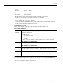
Disposal
Unusable electrical and electronic devices or modules must not be disposed
of with normal household refuse. They must be disposed of in compliance
with the applicable regulations and directives (e.g. WEEE in Europe).
Packaging film for the FAP-OTC 420/FAP-DOTC420
The packaging bag used for multisensor detectors with C sensor consists of tear-resistant PEALU laminated film and may be disposed of with the household refuse.
Defective detectors are exchanged and should be disposed of in accordance with legal
regulations.
8.7
Additional documentation
NOTICE!
For those with access rights, the current product information and the installation guide
enclosed with the device are available in PDF format from
the Bosch Security Systems Extranet at http://www.boschbest.de.
F.01U.003.449 | 7.2 | 2010.05
Product Information
Bosch Sicherheitssysteme GmbH
Automatic Fire Detectors LSN improved
version
9
Technical Data | en
35
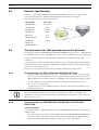
Technical Data
DO detectors
Detector Type
FAP-DOTC420
Detection principle
FAP-DOT420
FAP-DO420
Scattered-light
Combination of:
–
Scattered-light measurement
–
Measurement of absolute
measurement
temperature and temperature
increase
–
Combustion
-
-
gas
measurement
Special features
–
Two optical sensors
–
Contamination detection
–
Drift compensation in the optical sensor
–
Operation switching/sensor
-
deactivation in the optical unit and
in the thermal unit
Operating voltage
15 V DC to 33 V DC
Current consumption
< 0.55 mA
Individual display
Two-color LED (red/green)
Alarm output
Per data word by two-wire signal line
Indicator output
Open collector connects 0 V over 1.5 kilohm, max. 15 mA
Response sensitivity (basic
data)
–
Optical sensor
–
Thermal differential
< 0.15 dB/m (EN 54-7)
–
Thermal maximum unit
–
Chemical sensor
EN 54-5
-
> 54 °C/> 69 °C
unit
ppm range
Max. monitoring area
-
-
120 m2 (observe VdS guidelines)
Max. installation height
16 m (observe VdS guidelines)
Permitted air speed
20 m/s
Permissible operating
-10 °C. . . +50 °C
-20 °C. . . +50 °C
-20 °C. . . +65 °C
temperature
Permitted relative humidity
Protection category
< 95% (non-condensing)
IP 40/IP 43 with detector base with damp room seal
according to EN 60529
Color code
2 yellow rings
2 black rings
2 gray rings
Dimensions without base
∅ 99.5 x 52 mm
Dimensions with base
∅ 120 x 63.5 mm
Housing material/color
ABS/white, similar to RAL 9010, matte surface
Weight without packaging
Approx. 80 g
Approx. 75 g
Approx. 75 g
Weight with packaging
Approx. 135 g
Approx. 125 g
Approx. 125 g
Product ID
F.01U.116.034
F.01U.116.033
F.01U.116.032
Bosch Sicherheitssysteme GmbH
Product Information
F.01U.003.449 | 7.2 | 2010.05
36
Automatic Fire Detectors LSN improved
version
en | Technical Data
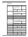
Multisensor detector
Detector type
FAP-OTC 420
Detection principle
FAP-OT 420
Combination of:
Combination of:
–
–
–
–
Scattered-light
Scattered-light
measurement
measurement
Measurement of absolute –
Measurement of absolute
temperature and
temperature and
temperature increase
temperature increase
Combustion gas
measurement
Special features
–
Contamination detection
–
Contamination detection
–
Drift compensation in the –
Drift compensation in the
optical sensor and the
optical sensor
–
gas sensor
–
Operation switching/
Operation switching/
sensor deactivation in
sensor deactivation in
the optical unit and in the
the optical unit and in the
thermal unit
thermal unit
Operating voltage
15 V DC to 33 V DC
Current consumption
< 0.55 mA
Individual display
Two-color LED (red/green)
Alarm output
Per data word by two-wire signal line
Indicator output
Open collector connects 0 V over 1.5 kilohm, max. 15 mA
Response sensitivity (basic
–
data)
–
Optical sensor:
Optical sensor:
< 0.15 dB/m (EN 54-7)
< 0.15 dB/m (EN 54-7)
–
Thermal differential unit:
–
Thermal differential unit:
EN 54-5
EN 54-5
–
Thermal maximum unit:
–
Chemical sensor: ppm
–
Thermal maximum unit:
> 54 °C/> 69 °C
> 54 °C/> 69 °C
range
Max. monitoring area
120 m2 (observe VdS guidelines)
Max. installation height
16 m (observe VdS guidelines)
Permitted air speed
20 m/s
Permissible operating
-10 °C. . . +50 °C
-20 °C. . . +50 °C
temperature
Permitted relative humidity
< 95% (non-condensing)
Protection category
according to EN 60529
Color code
IP 40 /
IP 43 with detector base with damp room seal
yellow ring
black ring
Dimensions without base
∅ 99.5 x 52 mm
Dimensions with base
∅ 120 x 63.5 mm
Housing material/color
ABS/white, similar to RAL 9010, matte surface
Weight without packaging
Approx. 80 g
Approx. 75 g
Weight with packaging
Approx. 125 g
Approx. 115 g
Product ID
F.01U.508.816
F.01U.508.815
F.01U.003.449 | 7.2 | 2010.05
Product Information
Bosch Sicherheitssysteme GmbH
Automatic Fire Detectors LSN improved
version
Technical Data | en
37
Smoke and heat detectors
Detector type
FAP-O 420 / FAP-O 420 KKW
Detection principle
Scattered-light measurement
FAH-T 420 / FAH-T 420 KKW
Measurement of absolute
temperature and temperature
increase
Special features
–
FAH-T 420 KKW:
–
Contamination detection
–
Drift compensation in the
For use in areas with
optical sensor
elevated radioactivity
–
FAP-O 420 KKW:
For use in areas with
elevated radioactivity
Operating voltage
15 V DC to 33 V DC
Current consumption
< 0.55 mA
Individual display
Two-color LED (red/green)
alarm output
Per data word by two-wire signal line
Indicator output
Open collector connects 0 V over 1.5 kilohm, max. 15 mA
Response sensitivity (basic
< 0.15 dB/m (EN 54-7)
–
data)
Thermal differential unit:
EN 54-5
–
Thermal maximum unit:
> 54 °C/> 69 °C
Max. monitoring area
Max. installation height
120 m2 (observe VdS
40 m2 (observe VdS
guidelines)
guidelines)
16 m (observe VdS
7.5 m (observe VdS
guidelines)
guidelines)
Permitted air speed
20 m/s
Permissible operating
-20 °C. . . +65 °C
-20 °C. . . +50 °C
temperature
Permitted relative humidity
< 95% (non-condensing)
Protection category
according to EN 60529
IP 40
IP 43 with detector base with damp room seal
Color code
-
red ring
Dimensions without base
∅ 99.5 x 52 mm
Dimensions with base
∅ 120 x 63.5 mm
Housing material/color
ABS/white, similar to RAL 9010, matte surface
Weight without packaging
Approx. 75 g
Weight with packaging
Approx. 115 g
Product ID
Bosch Sicherheitssysteme GmbH
F.01U.508.813 /
F.01U.508.915 /
F.01U.508.687
F.01U.508.686
Product Information
F.01U.003.449 | 7.2 | 2010.05
38
A
Automatic Fire Detectors LSN improved
version
en |
Abbreviations
ABS
AcrylonitrileButadieneStyrene
DIBt
Deutsches Institut für Bautechnik (German Institute for Technology)
DIN
German Institute for Standardization
DO
Dual-optical
DOT
Dual-optical and thermal
DOTC
Dual-optical, thermal and chemical
EN
European Standard
Convention Conventional technology
al
LED
Light Emitting Diode
LSN
Local Security Network
PI
Product Information
PP
Polypropylene
UEZ
Universelle Europazentrale (Universal European Central)
UGM
Universelle Gefahrenmeldezentrale (Universal danger detection system)
VDE
Association of German Electrical Engineers
VdS
VdS Schadenverhütung GmbH
OTC
Optical/thermal/chemical (gas)
OT
Optical/thermal
O
Optical
T
Thermal
F.01U.003.449 | 7.2 | 2010.05
Product Information
Bosch Sicherheitssysteme GmbH
Bosch Sicherheitssysteme GmbH
Robert-Koch-Straße 100
D-85521 Ottobrunn
Germany
Telefon
+49 89 6290-0
Fax
+49 89 6290-1020
www.boschsecurity.com
© Bosch Sicherheitssysteme GmbH, 2009


![General design guidance [PDF 950KB]](http://vs1.manualzilla.com/store/data/005804077_1-5fec14441b6361d04901f77e13b8a9c0-150x150.png)