1
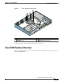
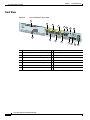
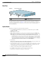
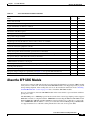
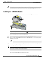
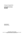
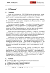
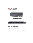
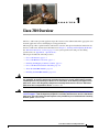
C H A P T E R
1
Cisco 7301 Overview
The Cisco 7301 router provides application-specific features for broadband subscriber aggregation and
network application services with high processing performance.
This chapter provides a quick hardware and features overview and options installation instructions for
the Cisco 7301 router. For functional information see Chapter 3, “Starting and Configuring the Router,”
the “Functional Overview” section on page 3-1. For system specifications and port and cabling
specifications, see Appendix A, “Specifications.”
This chapter includes the following sections:
•
Cisco 7301 Features, page 1-2
•
Cisco 7301 Hardware Overview, page 1-3
•
Checking the Shipping Container Contents, page 1-7
•
Cisco 7301 Router Installation Checklist, page 1-8
•
About the SFP GBIC Module, page 1-9
•
Installing the SFP GBIC Module, page 1-11
Warning
This warning means danger. You are in a situation that could cause bodily injury. Before you work on
any equipment, be aware of the hazards involved with electrical circuitry and be familiar with the
standard practices for preventing accidents. To see translations of the warnings that appear in this
publication, refer to the CRegulatory Compliance and Safety Information for the Cisco 7301 Router
publication that accompanied this device. Statement 1071
Warning
Before you install, operate, or service the system, read the “Preparing to Install the Cisco 7301 Router”
section on page 2-1 and the Regulatory Compliance and Safety Information for the Cisco 7301 Router
publication. These documents provide important safety information you should know before working
with the system. Statement 200
Cisco 7301 Installation and Configuration Guide
OL-5418-07
1-1
Chapter 1
Cisco 7301 Overview
Cisco 7301 Features
Cisco 7301 Features
Each Cisco 7301 router consists of the following features:
•
Small form-factor—One rack-unit (RU) high with stacking capability:
1.73 in. x 17.3 in. x 13.87 in. (4.39 cm x 43.9 cm x 35.23 cm). The weight is approximately 10.5 lbs
(4.76 kg).
•
Three native Gigabit Ethernet interfaces—six ports:
– Three optical fiber Gigabit Ethernet (1000 Mbps) ports that use a small form factor pluggable
(SFP) Gigabit Interface Converter (GBIC) modules with LC connectors
– Three Gigabit Ethernet (10/100/1000 Mbps) ports with RJ-45 connectors (any three ports are
available at any one time)
•
Both 25-MHz and 50-MHz port adapter operation
•
A 64- or 128-MB CompactFlash Disk
•
SFP GBIC modules: Three Gigabit Ethernet SX, LH, ZX module options, 1000BASE-T SFP
(copper) module, and several coarse wavelength-division multiplexing CWDM SFP modules
•
Power supplies:
– Single or dual AC power supplies
– Single 24V DC power supply
– Dual 48V DC power supply
•
BCM 1250 integrated dual processors that operates at an internal clock speed of 700 MHz
•
512-KB Boot ROM
•
32-MB Boot Flash
•
Three SDRAM memory options: 256 MB, 512 MB, and 1 GB
•
Auxiliary port
•
Console port
•
Online insertion and removal (OIR)—Allows you to add, replace, or remove port adapters with
minimal interruption of the system
•
Environmental monitoring and reporting functions—Allow you to maintain normal system
operation by resolving adverse environmental conditions prior to loss of operation
•
Downloadable software—Allows you to load new images into Flash memory remotely, without
having to physically access the router, for fast, reliable upgrades
•
Front-to-back airflow—Allows you to mount the router from either front or back into 19-inch
two-post racks and 21–23-inch four-post racks
Cisco 7301 Installation and Configuration Guide
1-2
OL-5418-07
Chapter 1
Cisco 7301 Overview
Cisco 7301 Hardware Overview
Figure 1-1
Cisco 7301 Router—Interior View
4
2
3
1
A
B
Hz
/6 0
, 50 5A
, 2A- 60 V=
24 0V, 48
10 0- 9A
24 V=
M
US
T
AC STAT
MP
CO H
FLAS
0/2
ET
RN
RX
ETHE LINK
IC
BIT
GB
GIGA
TX
RJ45
EN
80957
ALAR
E
OL
NS
CO
X
AU
0/1
ET
RN
RX
ETHE LINK
IC
BIT
GB
GIGA
TX
0/0
ET
RN
RX
ETHE LINK
IC
BIT
GB
GIGA
TX
SLOT
1
RJ45
RJ45
EN
EN
ATM
1
CO
730
EN
AB
LE
D
RX
CE
RX LLS
CA
RX RRIE
AL
R
AR
M
CIS
1
Temperature sensor 2 (U5)
3
SODIMM 2 (J2)
2
SODIMM 1 (J1)
4
BCM 1250 Processor (U31)
Temperature sensor 1 (U62) is on the underneath side of the board.
Cisco 7301 Hardware Overview
This section provides you with an overview of the hardware including LEDs, front and rear views, and
interior part identification.
Cisco 7301 Installation and Configuration Guide
OL-5418-07
1-3
Chapter 1
Cisco 7301 Overview
Cisco 7301 Hardware Overview
Front View
Figure 1-2
Cisco 7301 Router—Front View
1
3
5
7
R
9 10
ATM
SLOT 1
GIGABIT ETH
ERNET 0/0
RJ45 EN
LINK
TX GBIC
RX
GIGABIT ETH
ERNET 0/1
RJ45 EN
LINK
TX GBIC
RX
GIGABIT ETH
ERNET 0/2
RJ45 EN
LINK
TX GBIC
AUX
RX
CISCO 73
01
12
14
CONSOLE
100 -24 0V,
2A, 50/ 60
Hz
24V =9 A,
48 - 60V =5
A
ALARM
COMPACT
FLASH
STATUS
B
2
A
4
6
8
11 13
15
16
1
Port adapter slot (with installed port adapter) 9
2
Port adapter latch
10 Console port
3
Gigabit Ethernet 0/0—RJ-45 port
11 CompactFlash Disk ejector button
4
Gigabit Ethernet 0/0—SFP GBIC port
12 Ground for ESD wrist strap with banana jack
5
Gigabit Ethernet 0/1—RJ-45 port
13 Alarm port
6
Gigabit Ethernet 0/1—SFP GBIC port
14 Power switch
7
Gigabit Ethernet 0/2—RJ-45 port
15 CompactFlash Disk slot
8
Gigabit Ethernet 0/2—SFP GBIC port
16 Power connector
Auxiliary port
Cisco 7301 Installation and Configuration Guide
1-4
80265
D
R
LE LS RIE M
AB EL AR AR
EN RX C RX C X AL
OL-5418-07
Chapter 1
Cisco 7301 Overview
Cisco 7301 Hardware Overview
LEDs
Figure 1-3
Cisco 7301 Router—LEDs
GIGABIT ETH
ERNET 0/0
RJ45 EN
LINK
TX GBIC
RX
GIGABIT ETH
ERNET 0/1
RJ45 EN
LINK
TX GBIC
RX
GIGABIT ETH
ERNET 0/2
RJ45 EN
LINK
TX GBIC
RX
AUX
CONSOLE
CISCO 73
ALARM
01
B
3
4
5
6
80266
2
A
1
100 -24 0V,
2A, 50/ 60
Hz
24V =9 A,
48 - 60V =5
A
COMPACT
FLASH
STATUS
7
No.
LED Label
LED
Color
Status
LED flashes when
there is traffic
1
LINK (0/0)
LINK (0/0)
Green
—
Yes
2
RJ-45 EN (0/0)
RJ-45 enable (0/0)
Green
In the Power Up state,
the LED is on
No, remains
constantly on
3
LINK (0/1)
LINK (0/1)
Green
—
Yes
4
RJ-45 EN (0/1)
RJ-45 enable (0/1)
Green
In the Power Up state,
the LED is on
No, remains
constantly on
5
LINK (0/2)
LINK (0/2)
Green
—
Yes
6
RJ-45 EN (0/2)
RJ-45 enable (0/2)
Green
In the Power Up state,
the LED is on
No, remains
constantly on
7
STATUS
System status
Amber while the
system boots
—
—
Green when the
system is
operational
In the Power Up state,
the LED is on
No, remains
constantly on
Cisco 7301 Installation and Configuration Guide
OL-5418-07
1-5
Chapter 1
Cisco 7301 Overview
Cisco 7301 Hardware Overview
Rear View
Cisco 7301—Rear View
80267
Figure 1-4
1
2
1
2
Fan
Grounding connector
Five internal fans draw cooling air into the chassis and across internal components to maintain an
acceptable operating temperature. (See Figure 1-4.) The five fans are located at the rear of the chassis as
is the chassis grounding connector that provide a chassis ground connection for ESD equipment or a
two-hole grounding lug.
System Board
Internally, the system board contains the following components:
•
Two SODIMM DDR-SDRAM memory modules that are available in three options: 128 MB,
256 MB, and 512 MB
•
BCM 1250 processor system
•
BCM 1250 integrated dual processor that operates at an internal clock speed of 700 MHz. The
BCM 1250 processor maintains and executes the system management functions for the Cisco 7301
router. The processor also performs some memory and environmental monitoring functions.
– The BCM 1250 serves as the system controller. It interconnects the processor with the double
data rate synchronous dynamic random-access memory (DDR-SDRAM) controller, lightning
data transport (LDT) bus, and the three direct-interface Gigabit Ethernet interfaces, and the port
adapter PCI bus, which allows the port adapter access to DDR-SDRAM.
•
Cache memory
The processor system has two levels of cache: primary and secondary cache that are internal to the
microprocessor with secondary unified cache for data and instruction.
•
Three Gigabit Ethernet interfaces: (six ports: three SFP GBIC [optical] and three RJ-45s [copper]).
Any three ports are available at the same time and are linked directly to the BCM 1250 system.
•
A CompactFlash Disk for storing the default Cisco IOS software image.
•
Auxiliary port with full data terminal equipment (DTE) functionality.
•
Boot ROM for storing sufficient code for booting the Cisco IOS software.
•
Flash memory for storing the boot helper (boot loader) image.
Cisco 7301 Installation and Configuration Guide
1-6
OL-5418-07
Chapter 1
Cisco 7301 Overview
Checking the Shipping Container Contents
•
NVRAM for storing the system configuration and environmental monitoring logs. NVRAM uses
lithium batteries to maintain its contents when disconnected from power.
•
Two environmental sensors for monitoring the internal temperature of the chassis.
System Management Functions
The Cisco 7301 processor system performs the following system management functions:
•
Sending and receiving routing protocol updates
•
Managing tables, caches, and buffers
•
Monitoring interface and environmental status
•
Providing Simple Network Management Protocol (SNMP) management through the console and
Telnet interface
•
Accounting for and switching of data traffic
•
Booting and reloading images
•
Managing the port adapter (including recognition and initialization during online insertion and
removal)
The Cisco 7301 router supports multiprotocol, multimedia routing and bridging with a wide variety of
protocols and port adapters.
Checking the Shipping Container Contents
Use the Cisco 7301 components list to check the contents of the Cisco 7301 router shipping container.
Do not discard the shipping container. You need the container if you move or ship the Cisco 7301 router
in the future.
Cisco 7301 Installation and Configuration Guide
OL-5418-07
1-7
Chapter 1
Cisco 7301 Overview
Cisco 7301 Router Installation Checklist
Table 1-1
Cisco 7301 Components List
Component
Description
Chassis
Cisco 7301 chassis configured with a single or dual AC or DC power supply and port
adapter filler plate.
Accessories:
The following accessories might arrive in separate shipping containers:
•
Rack-mount and
cable-management kit
Two rack-mount brackets, one cable-management bracket, four 12-24 x 0.5-in.
screws to secure the rack-mount brackets to the chassis, four 8-18 x .37-in. screws
to secure the rack-mount brackets to a 19-inch rack, four 8 x .375-in. screws to
secure the rack-mount brackets to a 21–23-inch rack, and one M4 x 20-mm screw to
attach the cable-management bracket to the rack-mount bracket
•
AC power
cable-retention clip
If a single AC power supply is ordered, an AC power cable-retention clip ships
•
Power cables
If ordered, router hardware and software documentation and the Cisco
Documentation CD-ROM package1
•
Documentation
Optional Equipment
Received
An AC power cable, if an AC power supply was ordered
Examples: Port adapter, SFP GBIC modules , network interface cables, transceivers,
special connectors and so on
1. Titles and quantities of documents will vary. You must order the type and quantity of documentation sets when you order the hardware.
Note
We no longer ship the entire router documentation set automatically with each system. You must
specifically order the documentation as part of the sales order. If you ordered documentation and did not
receive it, we will ship the documents to you within 24 hours. To order documents, contact a customer
service representative.
Cisco 7301 Router Installation Checklist
To assist you with your installation and to provide a historical record of what was done by whom,
photocopy the Cisco 7301 Router Installation Checklist, Table 1-2 on page 1-9. Indicate when each
procedure or verification is completed. When the checklist is completed, place it in your site log along
with the other records for your new router.
Information on replacing internal field-replaceable units (FRUs) is found in Chapter 4, “Installing and
Removing Field-Replaceable Units.”
Cisco 7301 Installation and Configuration Guide
1-8
OL-5418-07
Chapter 1
Cisco 7301 Overview
About the SFP GBIC Module
Table 1-2
Cisco 7301 Router Installation Checklist
Verified
By
Task
Date
Date router received
Router and all accessories unpacked
Types and numbers of interfaces verified
Safety recommendations and guidelines reviewed
Installation Checklist copied
Site log established and background information entered
Site power voltages verified
Site environmental specifications verified
Required passwords, IP addresses, device names, and so on, available
Required tools available
Network connection equipment available
Router mounted in rack (optional)
Cable-management bracket installed (optional but recommended)
AC power cable(s) connected to AC source(s) and router; cable-retention clip secured
DC power cable(s) connected to DC source(s) and router
Network interface cables and devices connected
ASCII terminal attached to console port
Console port set for 9600 baud, 8 data bits, no parity, and 1 stop bits (9600 8N1)
System power turned on
System boot complete (STATUS LED is on)
I/O ports and port adapter are operational (see Figure 1-3 for specific LED information)
Correct hardware configuration displayed after system banner appears
About the SFP GBIC Module
You may have ordered a SFP (small form-factor pluggable) Gigabit Interface Converter (GBIC) module
with your Cisco 7301 router. You must install the SFP GBIC module. It is shipped separately to prevent
damage during shipment. After reading this section, use the installation instructions in the “Installing
the SFP GBIC Module” section on page 1-11 the to install the SFP GBIC modules.
For ease of installation, insert the SFP GBICmodule in the router while it is powered down and before
placing it in a rack.
The SFP GBIC port is a 1000-Mbps optical interface in the form of an LC-type duplex port that supports
IEEE 802.3z interfaces compliant with the 1000BASEX standard. Gigabit Ethernet SFP GBIC models
GLC-SX-MM, GLC-LH-SM, and GLC-ZX-SM are supported in the Cisco 7301 router, as well as the
Cisco 1000BASE-T SFP. In addition, a variety of Coarse Wave Division Multiplexing (CWDM) SFPs
are supportedon the Cisco 7301. The cabling information is the same for all optical SFPs.
Cisco 7301 Installation and Configuration Guide
OL-5418-07
1-9
Chapter 1
Cisco 7301 Overview
About the SFP GBIC Module
Also see “SFP GBIC Module Configurations” section on page A-4, the Gigabit Interface Converter
(GBIC) and Small Form-Factor Pluggable(SFP) GBIC Installation Inforamtion and Specifications, and
the Coarse Wavelength-Division Multiplexing SFP Compatability Matrix.
For optical connection cleaning information, see the Inspection and Cleaning Procedures for Fiber-Optic
Connections document.
Figure 1-5
Types of SFP GBIC Module Latches
2
3
80755
1
Note
1
Sliding latch
2
Swing and slide latch
3
Swing latch
The SFP GBIC module must be installed before you connect the cables to it.
•
The SPF GBIC module has three types of latches, which are also the removal mechanism. See
Figure 1-5. There is no correlation of the type of latch to the model (such as SX or LH) or
technology type (such as Gigabit Ethernet) of SFP modules. Always read the label on the SFP GBIC
module to determine the technology type, and model.
•
You can install and remove Gigabit Ethernet SFP GBIC modules with power on to the system.
•
Disconnect all cables before removing or installing a Gigabit Ethernet SFP module. We strongly
recommend that you do not install or remove the SFP GBIC with optical fiber cables attached to it.
•
SFP GBIC modules are keyed to prevent incorrect insertion.
Warning
Invisible laser radiation may be emitted from disconnected fibers or connectors. Do not stare into
beams or view directly with optical instruments. Statement 1051
Warning
Class 1 laser product. Statement 1008
Warning
Class 1 LED product. Statement 1027
Cisco 7301 Installation and Configuration Guide
1-10
OL-5418-07
Chapter 1
Cisco 7301 Overview
Installing the SFP GBIC Module
Warning
During this procedure, wear grounding wrist straps to avoid ESD damage to the card. Do not directly
touch the backplane with your hand or any metal tool, or you could shock yourself. Statement 94
Installing the SFP GBIC Module
Figure 1-6
Inserting a SFP GBIC Module into the Cisco 7301 Gigabit Ethernet Port 0/1
TX GBIC
RX
1
ETHERNET
0/0
LINK
TX GBIC
RX
TX
GIGABIT ET
HERNET 0/1
RJ45 EN
LINK
TX GBIC
RX
LINK
TX GBIC
RX
AUX
CONSOLE
RX
COMPAC
FLASH
80269
SERIES
2
1
GIGABIT ET
HERNET 0/2
RJ45 EN
SFP GBIC port 0/1
2
SFP GBIC module
Use the following procedure to install a SFP GBICmodule:
Step 1
Attach an ESD-preventive wrist strap between you and an unpainted chassis surface.
Step 2
Locate the label on the SFP GBIC module and turn the SFP GBIC module so the label is on top and the
alignment groove is down.
Note
The SFP GBIC module is keyed so that it cannot be inserted incorrectly.
Step 3
Insert the SFP GBIC module into SFP GBIC port 0/1, 0/2, or 0/3. The SFP GBIC module snaps into place
when you have completely and properly inserted it.
Step 4
Repeat Step 2 if you are inserting a second or third SFP GBIC module.
Note
Do not remove the plug from the SFP GBIC optical bores until you are ready to install the network
interface optical fiber cable. Save the plug for future use.
This completes the SFP GBIC module installation procedure.
Cisco 7301 Installation and Configuration Guide
OL-5418-07
1-11
Chapter 1
Cisco 7301 Overview
Installing the SFP GBIC Module
For information on removing and installing other options, see Chapter 4, “Installing and Removing
Field-Replaceable Units.”
For rack-mounting and cabling procedures, see Chapter 2, “Rack-Mounting, Tabletop Installation, and
Cabling.”
Cisco 7301 Installation and Configuration Guide
1-12
OL-5418-07