1
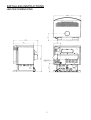
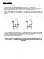
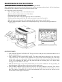
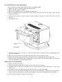
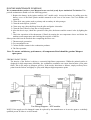
Manual
Owners &
Installation
Monaco
Gas Fires
PLEASE KEEP THESE INSTRUCTIONS
FOR FUTURE REFERENCE
WARNING
Improper installation, adjustment, alteration,
service or maintenance can cause injury or
property damage.
For assistance or additional information
consult an authorized technichian, or your
Masport Gas Fire Dealer.
FOR YOUR SAFETY
Do not store or use gasoline or other
flammable vapours and liquids in the vicinity
of this appliance
Installation and service must be performed by
authorized personnel.
Metal Fab Industies Limited - New Zealand
PO Box 58 473
Greenmount
Auckland
FOR YOUR SAFETY
What to do if you smell gas
not try to light any
• Do
appliance
not touch any
• Do
electrical switch
not use any phone
• Do
in your building
close the
• Immediately
shutoff valve behind the
•
heater
Call the technician
Metal Fab PTY - Australia
Unit 2, 205 Abbotts Road
Dendenong South
Victoria 3175
591558
THE INSTRUCTIONS IN THIS MANUAL APPLY TO
MASPORT MONACO GAS FIRES.
THE MODELS COVERED ARE:For use with Natural Gas:MONACO ACC NG,
MONACO ECS NG.
For use with Liquid Propane Gas (LPG):MONACO ACC LP,
MONACO ECS LP.
(ACC = Accessory, ECS = Electronic Control System)
WARNING.
Installation of all gas appliances MUST be carried out only by an Authorised
Installer.
The heater must be installed according to these instructions and in compliance with
all relevant building, gas-fitting, electrical and other Statutory Regulations (e.g. AS
5601 (AG-601), NZS 5261). Any shortcomings in the appliance and flue installation
will be the responsibility of the installer, and Masport Ltd will not be accountable for
any such failings or their consequences.
The guard is fitted to this appliance (Australia only) to reduce the risk of fire or
injury from burns and no part of it should be permanently removed. For the
protection of young children or the infirm, a secondary guard is required.
These appliances must not be installed in mobile homes.
We recommend that you have your heater checked yearly by an Authorised
Technician.
BEFORE INSTALLATION COMMENCES, check the data plate on the rear of the
heater cabinet to verify that it is the correct type to suit your gas and also that the gas
consumption rate is correct for your application.
CONTENTS:OPERATING INSTRUCTIONS ................ 2, 3, 4
Cleaning instructions .....................................4
INSTALLING INSTRUCTIONS .......................5
Heater dimensions.........................................5
Minimum installation clearances ....................6
Positioning the heater....................................6
INSTALLING PROCEDURE ............................6
Gas ...............................................................6
Thermostats ..................................................7
Gas pressure adjustment................................7
Fan ...............................................................7
Flue ..............................................................7
Ember placement...........................................8
Seismic restraint ............................................8
Test firing .....................................................9
MAINTENANCE INSTRUCTIONS................ 10
Log positions .............................................. 10
Access points .............................................. 10
Glass removal and assembly ........................ 11
Removing the burners ................................. 11
Routine maintenance ................................... 12
Fan wiring diagram (except ECS)................ 12
ECS wiring diagrams................................... 13
Trouble shooting................................... 14, 15
Annual Service Record................................ 16
THIS BOOK CONTAINS IMPORTANT INFORMATION.
IT MUST BE LEFT WITH THE PURCHASER TO BE
KEPT IN A SAFE PLACE FOR FUTURE REFERENCE.
1
OPERATING INSTRUCTIONS
DO NOT PLACE ARTICLES ON OR AGAINST THIS APPLIANCE.
DO NOT USE OR STORE FLAMMABLE MATERIALS NEAR THIS APPLIANCE.
DO NOT SPRAY AEROSOLS IN THE VICINITY OF THIS APPLIANCE WHILE IT IS IN
OPERATION.
LIGHTING AND RUNNING THE FIRE:• Open the gas supply valve behind the appliance, if fitted.
CAUTION: If the main burner has been alight, wait two to three minutes to allow it to cool before relighting it.
ACC MODELS:These can be in three configurations. They may be used as supplied, or they may be fitted with either a
battery operated wall-mounted thermostat which is wired directly to the heater, or a thermostat
contained in a portable remote control. With the latter option, a receiver is mounted on the stove
pedestal (on either side, at the rear, facing forward) to sense the signal from the remote control. The
remote control is battery powered, and the receiver requires a 240v AC power source. (Instructions
for fitting these optional thermostats are supplied with them.)
LIGHTING THE PILOT (ACC models):- Note: To avoid the risk of backburning, do not attempt to relight the fire less than three minutes after it has been extinguished.
The procedure for lighting the pilot is the same for all three ACC versions —
• Turn the HI-LO control knob fully anti-clockwise to the HI position. Push down and turn the PILOT
control knob anti-clockwise to the ‘PILOT’ position. Press and hold the PILOT control knob down
firmly. The battery igniter will generate a continuous spark across the terminals at the pilot light. It
may be necessary to hold the control knob down for some time before the pilot ignites if there is air in
the pilot light pipeline. If there is no spark when the control knob is held down in the PILOT position,
check the battery in the ignition module. It is mounted under the cover of the small black plastic
housing mounted on the back of the heater. One AA alkaline cell is required.
• Keep holding the control knob down for 15 seconds after the pilot ignites. Release the pressure on the
control knob – the pilot should remain alight when the knob rises.
• Turn the control knob fully anticlockwise to the ‘ON’ position. Note that the main burner will not light
until at least thirty seconds after the pilot is lit.
TURNING ON THE MAIN BURNER (ACC models):When no thermostat is fitted –
• Push down and turn the control knob fully anticlockwise to the ‘ON’ position and the fire will light at
full heat. There may be a strong smell the first time the logs are fired but this will soon disappear.
When the wall mounted programmable thermostat is fitted –
First ensure that good batteries (3 x AA alkaline) are fitted in the wall thermostat, that the slide switch
behind the hinged bottom cover is set to ‘HEAT’, and that the temperature setting on the thermostat is
above the prevailing room temperature. Full details of the wall-mounted thermostat and programming
instructions are supplied with it.
• Turn the control on the heater fully anticlockwise to the ‘ON’ position and the fire will light at full heat.
There may be a strong smell the first time the logs are fired but this will soon disappear.
When the IRRC 300 portable remote thermostat is fitted –
First check that good batteries are fitted in the remote control. To fit batteries (two AAA alkaline),
slide the cover below the display in the direction of the arrow and pull it further in the same direction
firmly until it disengages. Ensure that the receiver has a valid 230 volt AC supply.
• Move the switch on the receiver control box (at the rear of the pedestal)to ‘REMOTE’. (See page 5,
RECEIVER SWITCH POSITIONS).
2
• Check the display on the remote control. If it reads ‘OFF’, aim the remote control toward the receiver
and press the centre button on the remote to switch it to ‘ON’.
When the display shows ‘ON’, the SET TEMP will be displayed below the ROOM TEMP. For the
burner to light, the SET TEMP must be higher than the ROOM TEMP. Raise the SET TEMP, if
necessary, by pressing the right hand button.
• Turn the PILOT control fully anticlockwise to the ‘ON’ position and the fire will light at full heat.
There may be a strong smell the first time the logs are fired but this will soon disappear.
• After ten minutes, set the HI-LO control to give the desired heat output.
• At this stage you may turn on the fan by rotating the fan switch in either direction. The switch gives
three speeds and has an ‘OFF’ position. NOTE. The fan is also controlled by an internal switch which
will not permit it to start until the fire is hot (about ten minutes from cold on high fire) and will keep it
running for some time after the fire goes out.
PROGRAMMING THE REMOTE CONTROL
The control can be programmed to operate the heater at a desired later time. The controls for this are
under the sliding cover below the display. Programming instructions are in the instruction sheet
supplied with the remote control.
ECS MODELS:These have a remote control handpiece and thermostat connecting terminals on the rear of the heater.
If the wall thermostat is not fitted, a small wire bridging loop must be fitted across these terminals or
the heater will not light. If the battery operated wall thermostat is fitted, it must be switched to
‘HEAT’ (under the bottom hinged cover) and the SET temperature must be above the prevailing
ROOM temperature before the heater will light. The SET temperature can be altered by pressing the +
and – buttons alongside the display. If there is no display, check the thermostat batteries (3 x AA
alkaline).
• To avoid the risk of backburning, do not attempt to re-light the fire less than three minutes after it has
been extinguished.
• Check that the power switch at the wall is ‘ON’ and press the top round handpiece button while aiming
the handpiece toward the receiver on the right front corner of the pedestal foot. The red indicator light
on the handpiece should light and the red indicator light alongside the receiver (on the pedestal foot)
should light in response and remain alight after the handpiece button is released. If the handpiece
indicator does not light up, check the handpiece batteries (4xAAA cells). If the receiver indicator does
not light, press the small button alongside the receiver (on the pedestal foot). If the receiver indicator
still does not light, press the red ‘RESET’ button on the back of the heater and try again.
• As soon as the receiver indicator lights, a thirty second ignition sequence begins. After about three
seconds from the start, there will be a continuous spark at the pilot electrode which will light the pilot.
When starting for the first time, there will probably be air in the pilot line supply pipe, so ignition may
not occur immediately. If it has not lit within about thirty seconds, the spark will cease. In this event,
press the red RESET button on the back of the heater and try lighting again. If you need to press the
reset again, wait at least ten seconds before doing this. If there is a lot of air in the pipeline, it may be
necessary to repeat this reset procedure several times.
• When the pilot lights, the ECS system shuts down the ignition spark and then turns on the gas supply
to the main burner. This will ignite shortly after.
• Once the main burner is alight, the size of the flame can be adjusted using the top rocker switch on the
handpiece. Pressing + increases the flame. Note that the response to flame adjustment may take about
twenty seconds, so the rocker switch should be held down until the flame reaches the desired height.
• While the heater is being switched on and off by the wall thermostat (if fitted), the red indicator light
beside the receiver will remain alight, showing that the heater is ready to light again when the room
temperature falls. The flame will light at its last height setting. The pilot light extinguishes each time
the flame extinguishes.
• If the mains supply to the heater is switched off, the fire will light next time at the LOW flame setting,
but if the mains supply is uninterrupted, the flame will light again at its last setting.
3
• The lower rocker switch on the handpiece controls the fan, switching it to ‘OFF’, ‘LOW’, ‘MEDIUM’
and ‘HIGH’ sequentially. NOTE. The fan is also controlled by an internal switch which will not permit
it to start until the fire is hot (about ten minutes from cold on high fire) and will keep it running after
the fire goes out. The handpiece will not start the fan during the warm-up period, but it can pre-select
the speed at which the fan will start once the firebox is hot.
NOTE: Occasionally the electrical system may ‘lock up’. Turning off the mains supply for ten seconds
will clear this.
TURNING THE FIRE OFF:ACC MODELS :• Push down and turn the control to the ‘PILOT’ position. Alternatively, models fitted with wall
mounted or portable thermostats may be shut down at the thermostat. The pilot will remain alight.
• If the fan is running, it will stop after the firebox has cooled.
• To extinguish the pilot light, press the PILOT control knob part way down and turn it fully clockwise.
ECS MODELS:• To stop the fire immediately, press the TOP button on the handpiece once or press the small button by
the receiver (on the pedestal foot) once. The indicator light by the receiver will extinguish, the fire and
pilot light will shut down and the fan will stop. Alternatively, turning off the mains plug switch or
moving the slide switch on the wall thermostat away from ‘HEAT’ will extinguish the fire.
• To stop the fire after a delay of about 30 minutes, press the BOTTOM button on the handpiece. The
indicator light beside the receiver will start flashing and eventually the fire will shut down. Pressing the
delayed stop button again during the shutting down period will restore the heater to normal
continuous operation.
RECEIVER SWITCH POSITIONS (ACC models)
The receiver switch has three positions, ‘OFF’, ‘ON’ and ‘REMOTE’.
‘OFF’ prevents the main burner from being lit. This is a useful safety feature if children might play with the
remote control.
‘ON’ bypasses the remote control entirely, allowing the heater to be lit even though the batteries in the
receiver or remote control are dead, or, in the case of the RMT model, if the mains power supply has
failed. In this setting the thermostat is inactive and the heat output is fixed on LOW for RMT models. It
may be controlled manually on all other models.
‘REMOTE’ brings the remote control into full operation, allowing its in-built thermostat to match heat
output to the heating needs of the area the remote control is in, provided that the remote control is left
pointing toward the heater. For automatic heat control with RMT models, the remote control must be
‘ON’ in the ‘AUTO’ mode. The remote control can be set to automatically run the heater within any
desired time period. See the separate remote control operating instructions for full details.
CLEANING INSTRUCTIONS
The outside of the cabinet and glass should need no more than an occasional wipe with a damp cloth to
remove any dust which may have settled.
All visible flame gas heaters can produce small amounts of soot, particularly if the combustion air entry
slots under the heater are obstructed or the aeration air inlets are clogged with lint.
After a time, the inside of the glass may require cleaning. To do this, carefully remove the glass (See
Glass Removal and Assembly, page 11), and clean the inside surface with a non-abrasive cloth and a nonscratching type household cleaning liquid. Replace the parts as detailed on page 117, keeping fingerprints
off the inside glass surface.
No other user maintenance should be necessary. If you require any other service or adjustments, contact
your Installer or Dealer.
4
INSTALLING INSTRUCTIONS
HEATER DIMENSIONS
5
MINIMUM INSTALLATION CLEARANCES (To heat sensitive surfaces) g
g
NOTE: The clearances shown are for fire hazard only. For durability of finishes or surfaces you should contact
the relevant manufacturer for their specification. MASPORT accepts no responsibility for the deterioration of
surfaces or finishes.
NO FLOOR PROTECTOR (HEARTH) IS REQUIRED
ALCOVE INSTALLATION NOT PERMITTED
POSITIONING THE HEATER
Select a dry site on any rigid flooring surface, keeping in mind the following:• A central position free of strong draughts will ensure even heat dispersal.
• Check that the flue and its shielding will be able to pass through the ceiling space and roof without
interfering with any structural timberwork.
• The flue must terminate above the roof no less than 500mm clear of any part of the roof, and at least
1 metre horizontally from any neighbouring structure.
• The minimum specified clearance distances to heat sensitive materials MUST be maintained at all
times, and sufficient room will be needed to facilitate servicing the heater.
• Avoid positions where curtains or furniture might accidentally come too close to the heater.
• Select a location where the gas supply can be installed readily. An electrical outlet will also be
required.
INSTALLING PROCEDURE
GAS. Access to the gas connection point is obtained by removing the cover panel on the rear of the cabinet.
(Four screws)
Connection is made to the ACC models using a 1/2” BSP fitting. The ECS models for Australia have 1/2”
flare fittings, while the ECS models for New Zealand have 3/8” flare fittings.
In all cases a shut-off valve should be installed directly behind the heater to facilitate isolation of the heater
for servicing.
It is essential to purge all gas lines before making the connection to the heater to eliminate any swarf.
6
THERMOSTATS
ACC Models. Two accessory options are available:
• The hand-held IRRC Model 300 non-programmable remote thermostat.
• The wall-mounted programmable thermostat.
Instructions for installing both options are supplied with them.
ECS Models. An optional battery powered wall-mounted programmable thermostat is available.
GAS PRESSURE ADJUSTMENT. All pressure adjustments must be made while the heater is
operating on the ‘HIGH’ setting.
ACC NG and ACC LP. These have a pressure regulator inside the control valve. There are two test points
side by side on top of the control valve – the outlet pressure test point is the one closer to the flame size
control knob. If adjustment is necessary, uncouple the control rod from the top of the flame size control
knob, extract the screw from down the centre of this knob and pull the knob off vertically. The pressure is
then set by rotating the knurled plastic wheel exposed by removing the knob. Once the pressure is correct
(0.95 kPa for NG or 2.5 kPa for LP), care must be taken not to turn the plastic wheel as the knob is refitted in its maximum anti-clockwise position. This position is set when the skirt of the knob contacting the
adjacent metal up-stand. Rotate the knob clockwise and then fully anti-clockwise while observing the
pressure to verify that it is correct before replacing the retaining screw and re-coupling the control rod.
ECS NG and ECS LP. These also have a pressure regulator in the control valve. The outlet pressure test
point is on the top of the control valve and is the one remote from the gas inlet connection. There are two
pressure settings to adjust, high and low. Access to the adjusters is gained by first removing the heat shield
above the valve and then removing the protective transparent cap at the very top of the control valve
modulating coil. This will expose the central screw (low pressure adjuster) and a 10mm hexagonal nut
surrounding it (high pressure adjuster). Note that the modulating coil may be rotated through 90° if
necessary to provide easier access for pressure adjustments. Before adjusting the high pressure, the fire
must be alight and burning at the ‘HIGH’ setting. (Hold down the + end of the top rocker switch on the
handpiece for 30 seconds to ensure this).
Set the high pressure first. NG high pressure should be 0.95 kPa and LP high pressure should be 2.3 kPa.
Adjust, if necessary, by rotating the 10mm nut, screwing down to increase the pressure and up to decrease
it.
Before setting the low pressure, remove one of the blue wires connected to the top of the modulating coil.
There is no need to alter the handpiece control setting. Adjust the low pressure by rotating the central
Phillips head screw, taking care not to shift the position of the already adjusted 10mm hex. nut. Screw
down to increase the pressure. The correct low pressures are 1.0 kPa for LP and 0.40 kPa for NG.
Replace the protective cap on top of the adjusters, re-fit the blue wire to the modulating coil, rotate the
assembly above the coil to its original position and re-fit the heat shield above the valve.
FAN
ACC MODELS. These have a Thermodisc heat operated switch incorporated in the fan wiring circuit to
prevent the fan from running until the firebox has reached a reasonable working temperature. It will not be
possible to check the fan operation until about ten minutes after the fire has been lit on ‘HIGH’. When this
time has elapsed, check the operation of the fan on all speed settings. Verify correct operation.
ECS MODELS. These have a Thermodisc also (see above paragraph). Once the firebox has heated up, check
the fan operation by pressing the lower rocker switch on the handpiece. Pressing the + end repeatedly will
increase the speed through all four fan speed settings (three speeds and off), while pressing the – end will
step it down through the speeds. Verify correct operation.
FLUE. USE ONLY AN APPROVED FLUE SYSTEM.
NOTE. For safe operation, the flue must never be less than 900mm long.
1. Stand the heater in its proposed position, taking care to observe the minimum clearances shown on page
7. The heater does not require a floor protector (hearth).
2. Drop a plumb-bob from the ceiling to hang centrally in the flue socket of the heater and mark the
position on the ceiling. Drive a small nail through at this point and inspect the ceiling and roof to ensure
that the flue and its trim will be at least 25mm clear of any combustible material. The flue termination
requirements stated in 3 below will also need to be met.
7
3. Cut appropriate holes through the ceiling and roof material and install the flue in accordance with the
instructions accompanying it, taking care to provide any safety clearances specified in the instructions
(usually 25mm between the flue shield and any nearby combustible material). The installation must meet
the requirements of AS 5601 (AG 601) or NZS 5261 as appropriate. The top of the flue must be above
the roof, at least 500mm clear of any part of the roof and at least 1 metre horizontally from any
neighbouring structure. All flue sections must be securely coupled to each other.
4. Flash the flue at the point of exit through the roof, to prevent water entry, and fit the flue cowl.
It is the responsibility of the installer to ensure that the flue system is operating correctly. See
‘TEST FIRING’ below.
EMBER PLACEMENT
SEISMIC RESTRAINT
New Zealand regulations require that flued gas heaters be secured to prevent shifting in the event of an
earthquake. This is best done by fastening the heater to the floor right through the floor protector if one is
fitted. Fasten with two screws not less than 12 gauge or the equivalent in coach screws or toggle fasteners.
Anchor the appliance through the holes in the seismic restraint bracket or in the two angle brackets
supplied. The angle brackets attach at each side of the pedestal. If the seismic restraint bracket is used, it
can be fastened to the rear of the pedestal either before or after fitting the anchor screws. The small
centreline hole in the bracket will help in pre-positioning it.
Spire clip
Seismic Restraint Bracket
Screw
Secure through
these holes
Screw
Angle Bracket
Centreline Hole
8
TEST FIRING
It is absolutely essential that the installer test fires the heater before leaving the site.
If fitted, open the gas supply valve at the rear of the heater and check all gas joints for leakage using a leak
check solution or an electronic ‘sniffer’, NOT a naked flame.
Test fire the heater, following the lighting instructions on pages 2, 3 and 4 of this manual.
First check that the pilot light ignites satisfactorily. Initially it may take several attempts until the air is
purged from the pipeline. Once it has lit, extinguish it again and verify instant re-ignition.
Using the appropriate procedure as detailed for the heater model, light the main burner to verify satisfactory
ignition and cross-lighting. Repeat this procedure several times. Always wait two or three minutes after
turning off the main burner before lighting it again. The main burner should be test run for at least ten
minutes.
After the fire has been alight for five minutes on ‘HIGH’, hold a smoking taper or match at the exit of the
draught hood (behind the heater) to verify that the flue is drawing correctly and that flue gases are not
spilling into the room.
Drawn in: No spillage
Blown out: Spillage/Backdraughting
If a wall mounted or remote thermostat is fitted, verify the thermostat action by turning the set temperature
above and below the room ambient temperature to check that the burner turns on and off automatically.
Hand held remote thermostats must point toward the receiver for effective operation.
If a fan is fitted, check its operation at all speeds.
If satisfactory operation cannot be achieved, contact the Retailer for further advice.
IMPORTANT. It is the responsibility of the installer to instruct the customer on the safe and
correct operation of the appliance, and to ensure that this instruction booklet remains with
the customer.
9
MAINTENANCE INSTRUCTIONS
Maintenance must be carried out only by authorised personnel.
Minor adjustments can be made with the heater in its normal operating position, but it will be found more
convenient to move the heater away from the wall for major work.
If it is necessary to move the heater:• Shut off the gas supply at the valve behind the heater.
• Remove the access plate on the rear of the cabinet.
• Disconnect the gas line at the heater.
• Lift the flue trim about 75mm and support it with a wooden block.
• Slacken any flue clamp, and lift the flue while moving the heater from beneath it.
• Slide the heater away from the wall, supporting the flue and trim on a suitable spacer.
• Keep the heater upright at all times to avoid displacing the logs. The correct gas-log positions are
shown below.
ACCESS POINTS
1. THE CABINET REAR COVER PLATE. This gives access to the gas entry connection and the rear of
the gas control valve.
2. THE CABINET RIGHT HAND SIDE PANEL. The entire panel can be removed to give easy access
to the control valve. To remove it, first withdraw two screws under its bottom flange (one at the front
and the other at the rear of the panel). Pull the lower end of the side panel away from the heater until it
is clear of its mounting and then lower the panel until the two locating pegs on its upper flange
disengage from the cabinet. Lift it clear.
3. THE GLASS. See page 11 for removal instructions. Access is then available for the log assembly, the
pilot light, igniter points and flame safety sensor and the main burner.
4. THE ENTIRE CABINET may be removed if access to the heat exchanger is necessary. First remove
the glass and the cabinet right hand side panel, the fan, the draught diverter hood and the rear cover
plate. The cabinet is retained by five screws from underneath, three screws at the rear and two screws
on each front vertical edge of the firebox.
10
GLASS REMOVAL AND ASSEMBLY
Carry out these procedures only while the heater is standing upright.
1. Remove the louvre by lifting it upwards and outwards.
2. Remove the dress guard, if fitted.
3. Remove two fastening screws securing the top glass trim.
4. Prise forward the top glass trim and lift it clear. Note. This will release the top edges of the left and
right glass retainers.
5. Lift the glass retainers to remove them, keeping a hand on the glass to ensure that it does not fall
forward.
6. Lift the glass clear.
7. Assembly is the reverse of the above. Clean the inside surface of the glass and keep fingerprints off it
as it is re-assembled.
8. Place the glass in position, noting that the bottom edge of the glass has no gasket.
9. Replace the left and right glass retainers, fitting their lower ends behind the bottom glass trim.
10. Slide the top glass trim into place, making sure the top ends of the side glass retainers are captured.
Fit its two fastening screws and refit the louvre.
REMOVING THE BURNERS
1. Remove the glass (see above).
2. Lift the front and top logs out carefully, but leave the rear log in position.
3. Inside the firebox, remove the secondary air covers, one at each end of the front burner. (2 screws for
each cover)
4. If it is fitted, remove the flame guide plate which covers part of the front burner.
5. Remove the two front burner retaining screws and lift out the burner by raising the end opposite the
injector (the left hand end) first, and moving the burner to the left to disengage it from the injector.
6. Use the same procedure to remove the rear burner.
11
ROUTINE MAINTENANCE SCHEDULE
We recommend that you have your Masport heater serviced yearly by an Authorised Technician. This
periodic maintenance should cover the following points:1. Replace the battery in the igniter module (ACC models only). Access the battery by pulling open the
battery cover of the black plastic module mounted on the rear of the heater. One AA alkaline cell
required.
2. Clean all air entry points such as primary and secondary air inlet passages.
3. Clean the main injector jet holes.
4. Clean away any carbon build-up from the pilot and igniter electrodes.
5. Clean the fan (if fitted) of any lint or foreign matter.
6. After the above steps, check the operation of the pilot, the burners and the control valve by lighting the
fire.
7. Check the operation of the thermostat (if fitted) by turning the set temperature above and below the
ambient room temperature and checking the response of the fire.
Other points which can be checked after completing the above are:1. Thermocouple generation.
2. Gas consumption rate.
3. Carbon dioxide content in the combustion products.
4. The flue operation.
Note: To ensure satisfactory performance, all components fitted should be genuine Masport
spare parts.
FIREBOX PAINT FINISH
The interior of the firebox is subject to extremely high flame temperatures. Whilst the painted surface is
designed for high temperature durability, the combustion conditions can cause deterioration of the paint
finish. This is not unique to Masport gas fires. If the surface discolours or blisters, simply scuff any loose
paint from the firebox and lightly re-spray with Masport high temperature paint.
Fan Wiring Diagram - ACC models.
NOTE: If the supply cord is damaged it must be replaced by the manufacturer or its service agent or a similarly
qualified person in order to avoid a hazard.
12
NOTE: If the supply cord is damaged it must be replaced by the manufacturer or its service agent or a
similarly qualified person in order to avoid a hazard.
13
TROUBLE - SHOOTING
The following table lists possible problems and their likely causes. Most of these will require a professional
serviceman and we recommend that this work be performed by an Authorised Technician. If a problem cannot
be solved after referring to this table, please call the Retailer from whom the appliance was purchased. Refer to
your Warranty Card for details of Warranty cover.
PROBLEM
Pilot will not light and there is
no strong blue spark
POSSIBLE CAUSE(S)
SOLUTION
Faulty electrode wire or wire
connection(s).
Make sure wire is not shorting
and connections are firm at each
end.
ACC models. Faulty battery in
igniter
Fit a new AA alkaline cell in
igniter. (See routine
Maintenance).
ECS models.
No mains supply.
Handpiece faulty (no indicator
light).
Handpiece OK but no receiver
indicator light.
Restore mains supply.
Fit new batteries.
Aim handpiece at receiver –
move closer to receiver.
Press start switch beside receiver.
Press reset switch at rear and try
again.
Air in pilot pipeline.
Repeat starting attempts until air
is cleared.
Incorrect lighting procedure.
Follow the instructions in this
manual.
No gas supply at heater.
Check for closed gas valve(s) or
faulty gas supply lines.
Pilot jet blocked.
Clean jet
No fuel in LPG system.
Replenish LPG supply.
Pilot stays alight but main
burner will not light.
Thermostat, (where fitted), is
switched to OFF or set to a low
temperature.
Check thermostat setting. Switch
to ON or set to a higher
temperature.
Smell of flue gas in the room.
Check for flue blockage, negative
Flue gas spilling from the
draught diverter at the rear of the air pressure in the room or
circumstances causing downheater.
draught.
Pilot will not light even
though there is a strong blue
spark.
14
PROBLEM
POSSIBLE CAUSE(S)
SOLUTION
Smell of gas in the room.
Pipe fittings may be leaking.
Check all joints for leaks,
including the gas supply system,
the pilot light supply tube, the
main burner supply tube and all
connections to the control valve.
Use ONLY a proper leak check
solution. NEVER USE AN
OPEN FLAME TO CHECK
FOR LEAKS.
A thin coating of black soot
forms inside the glass.
Combustion air supply restricted.
Clean all primary and secondary
air passageways.
Over-supply of gas.
Adjust gas delivery pressure at
test point.
Logs out of position.
Arrange logs correctly.
Residues of new logs being
burned off.
Follow glass cleaning directions
under Maintenance Instructions.
A white coating forms inside
the glass.
Fan hums but there is poor air Dirty fan impeller.
circulation.
No power to fan.
Fan will not run.
Disconnect electrical power.
Remove fan and clean impeller.
Faulty Thermodisc or wiring.
Loose fan loom plug.
Handpiece for ECS model
ineffective
Fire cycling on and off too
rapidly.
Fan should not run until firebox is
hot.
Call serviceman.
Check after removing fan.
Aim at receiver.– fit new
batteries.
Thermostat models only.
A large fire in a small room.
Incorrect positioning of
thermostat.
15
Turn flame down to a lower
setting.
Move hand thermostat or wall
thermostat further away from
heater hot air stream.
ANNUAL SERVICE RECORD
DATE
SERVICE DETAILS
16
SERVICED BY
Masport Gas Fires are manufactured in New Zealand by
MASPORT LTD. 1/37 MT WELLINGTON HIGHWAY.
P.O. Box 14-349 Panmure, Auckland New Zealand.
A.G.A. Approvals:
Monaco ACC NG, Monaco ACC LP – Both Certificate No. 5656
Monaco ECS NG, Monaco ECS LP – Both Certificate No. 5656
Installed by:-
Date:-