1
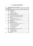
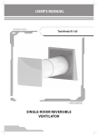
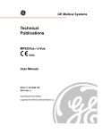
Powerware Series
®
Eaton 9395 Field Installed UPM
Mechanical Installation Manual
IMPORTANT SAFETY INSTRUCTIONS
SAVE THESE INSTRUCTIONS
This manual contains important instructions that you should follow during installation and maintenance of the UPS and batteries. Please
read all instructions before operating the equipment and save this manual for future reference.
CONSIGNES DE SÉCURITÉ IMPORTANTES
CONSERVER CES INSTRUCTIONS
Ce manuel comporte des instructions importantes que vous êtes invité à suivre lors de toute procédure d’installation et de maintenance
des batteries et de l’onduleur. Veuillez consulter entièrement ces instructions avant de faire fonctionner l’équipement et conserver ce
manuel afin de pouvoir vous y reporter ultérieurement.
WARNING
This is a product for restricted sales distribution to informed partners (EN/IEC 62040−2). Installation restrictions or additional measures
may be needed to prevent electromagnetic disturbances.
Eaton is a registered trademark of Eaton Corporation or its subsidiaries and affiliates.
ECopyright 2008–2009 Eaton Corporation, Raleigh, NC, USA. All rights reserved. No part of this document may be reproduced in any way without
the express written approval of Eaton Corporation.
Table of Contents
1
Introduction . . . . . . . . . . . . . . . . . . . . . . . . . . . . . . . . . . . . . . . . . . . . . . . . . . . . . . . . . . . . . . . . . . . . . . . . . . .
1.1
1.2
1.3
1.4
1.5
1−1
Using This Manual . . . . . . . . . . . . . . . . . . . . . . . . . . . . . . . . . . . . . . . . . . . . . . . . . . . . . . . . . . . . . . . . . . . . . . . . . . . . . . . . . . . .
Conventions Used in This Manual . . . . . . . . . . . . . . . . . . . . . . . . . . . . . . . . . . . . . . . . . . . . . . . . . . . . . . . . . . . . . . . . . . . . . . . . . .
Symbols, Controls, and Indicators . . . . . . . . . . . . . . . . . . . . . . . . . . . . . . . . . . . . . . . . . . . . . . . . . . . . . . . . . . . . . . . . . . . . . . . . . .
For More Information . . . . . . . . . . . . . . . . . . . . . . . . . . . . . . . . . . . . . . . . . . . . . . . . . . . . . . . . . . . . . . . . . . . . . . . . . . . . . . . . . . .
Getting Help . . . . . . . . . . . . . . . . . . . . . . . . . . . . . . . . . . . . . . . . . . . . . . . . . . . . . . . . . . . . . . . . . . . . . . . . . . . . . . . . . . . . . . . . .
1−1
1−1
1−3
1−4
1−4
2
Safety Warnings . . . . . . . . . . . . . . . . . . . . . . . . . . . . . . . . . . . . . . . . . . . . . . . . . . . . . . . . . . . . . . . . . . . . . . .
2−1
3
Field Installed UPM Installation Plan and Unpacking . . . . . . . . . . . . . . . . . . . . . . . . . . . . . . . . . . . . . . . . . .
3−1
3.1
3.2
3.3
4
Creating an Installation Plan . . . . . . . . . . . . . . . . . . . . . . . . . . . . . . . . . . . . . . . . . . . . . . . . . . . . . . . . . . . . . . . . . . . . . . . . . . . . . .
Preparing the Site . . . . . . . . . . . . . . . . . . . . . . . . . . . . . . . . . . . . . . . . . . . . . . . . . . . . . . . . . . . . . . . . . . . . . . . . . . . . . . . . . . . . .
Inspecting and Unpacking the FI−UPM Cabinet . . . . . . . . . . . . . . . . . . . . . . . . . . . . . . . . . . . . . . . . . . . . . . . . . . . . . . . . . . . . . . . . .
3−1
3−1
3−5
Field Installed UPM Installation . . . . . . . . . . . . . . . . . . . . . . . . . . . . . . . . . . . . . . . . . . . . . . . . . . . . . . . . . . .
4−1
4.1
4.2
4.3
4.4
4.5
4.6
Preliminary Installation Information . . . . . . . . . . . . . . . . . . . . . . . . . . . . . . . . . . . . . . . . . . . . . . . . . . . . . . . . . . . . . . . . . . . . . . . . .
Unloading the FI−UPM Cabinet from the Pallet . . . . . . . . . . . . . . . . . . . . . . . . . . . . . . . . . . . . . . . . . . . . . . . . . . . . . . . . . . . . . . . . .
Mechanical Installation . . . . . . . . . . . . . . . . . . . . . . . . . . . . . . . . . . . . . . . . . . . . . . . . . . . . . . . . . . . . . . . . . . . . . . . . . . . . . . . . .
Electrical Installation . . . . . . . . . . . . . . . . . . . . . . . . . . . . . . . . . . . . . . . . . . . . . . . . . . . . . . . . . . . . . . . . . . . . . . . . . . . . . . . . . . .
Initial Startup . . . . . . . . . . . . . . . . . . . . . . . . . . . . . . . . . . . . . . . . . . . . . . . . . . . . . . . . . . . . . . . . . . . . . . . . . . . . . . . . . . . . . . . .
Completing the Installation Checklist . . . . . . . . . . . . . . . . . . . . . . . . . . . . . . . . . . . . . . . . . . . . . . . . . . . . . . . . . . . . . . . . . . . . . . . .
4−1
4−1
4−3
4−5
4−5
4−5
Warranty . . . . . . . . . . . . . . . . . . . . . . . . . . . . . . . . . . . . . . . . . . . . . . . . . . . . . . . . . . . . . . . . . . . . . . . . . . . . . . . .
W−1
EATON 9395 Field Installed UPM Mechanical Installation Manual S 164201717 Rev 3 www.eaton.com/powerquality
i
TABLE OF CONTENTS
List of Figures
Figure 1-1. Powerware 9395 Field Installed UPM . . . . . . . . . . . . . . . . . . . . . . . . . . . . . . . . . . . . . . . . . . . . . . . . . . . . . . . . . . . . . .
Figure 3-1. FI−UPM Cabinet Dimensions (Front View) . . . . . . . . . . . . . . . . . . . . . . . . . . . . . . . . . . . . . . . . . . . . . . . . . . . . . . . . . . .
Figure 3-2. FI−UPM Cabinet Dimensions (Right Side View) . . . . . . . . . . . . . . . . . . . . . . . . . . . . . . . . . . . . . . . . . . . . . . . . . . . . . . .
Figure 3-3. FI−UPM Cabinet Dimensions (Top View) . . . . . . . . . . . . . . . . . . . . . . . . . . . . . . . . . . . . . . . . . . . . . . . . . . . . . . . . . . . .
Figure 3-4. FI−UPM Cabinet Dimensions (Bottom View) . . . . . . . . . . . . . . . . . . . . . . . . . . . . . . . . . . . . . . . . . . . . . . . . . . . . . . . . . .
Figure 3-5. FI−UPM Cabinet Dimensions (Bottom View with Mounting Brackets) . . . . . . . . . . . . . . . . . . . . . . . . . . . . . . . . . . . . . . . .
Figure 3-6. FI−UPM Cabinet Center of Gravity . . . . . . . . . . . . . . . . . . . . . . . . . . . . . . . . . . . . . . . . . . . . . . . . . . . . . . . . . . . . . . . .
Figure 3-7. Powerware 9395 FI−UPM Cabinet as Shipped on Pallet . . . . . . . . . . . . . . . . . . . . . . . . . . . . . . . . . . . . . . . . . . . . . . . . .
Figure 4-1. Removing the Left Side Shipping Bracket . . . . . . . . . . . . . . . . . . . . . . . . . . . . . . . . . . . . . . . . . . . . . . . . . . . . . . . . . . .
Figure 4-2. Removing the Right Side Shipping Bracket . . . . . . . . . . . . . . . . . . . . . . . . . . . . . . . . . . . . . . . . . . . . . . . . . . . . . . . . . .
Figure 4-3. UPS Cabinet Wire Entry Plate and Knockout Locations . . . . . . . . . . . . . . . . . . . . . . . . . . . . . . . . . . . . . . . . . . . . . . . . . .
ii
EATON 9395 Field Installed UPM Mechanical Installation Manual S 164201717 Rev 3 www.eaton.com/powerquality
1−2
3−3
3−3
3−4
3−4
3−4
3−5
3−6
4−2
4−3
4−4
Chapter 1
Figure 1Table 1
Introduction
The Eaton® 9395 Field Installed UPM (FI−UPM) provides increased capacity or N+1
redundancy for Eaton 9395 UPS systems. Capacity increase depends on the
capabilities of the originally installed system. The FI−UPM may be installed at any time
when power needs change. The module cabinet installs on the left side of the UPS
cabinet and wires directly to the UPS. No input or output wiring changes are needed
for a capacity increase if the original installation was wired with increased capacity in
mind. Operation remains the same as the original UPS.
The FI−UPM is housed in a single, free-standing cabinet with safety shields behind the
front panel for hazardous voltage protection. The cabinet matches the UPS cabinet in
style and color. Figure 1-1 shows the Eaton 9395 FI−UPM.
NOTE Wiring, startup, and operational checks must be performed by an authorized Eaton Customer Service
Engineer, or the warranty terms specified on page W−1 become void. This service is offered as part of the
sales contract for the FI−UPM. Contact an Eaton service representative in advance (usually a two−week notice
is required) to request service.
1.1
Using This Manual
This manual describes how to mechanically install the Eaton 9395 FI−UPM cabinet.
Electrical installation will be performed by an Eaton Customer Service Engineer. Read
and understand the procedures described in this manual to ensure trouble−free
installation.
1.2
Conventions Used in This Manual
This manual uses these type conventions:
S Bold type highlights important concepts in discussions, key terms in procedures,
and menu options, or represents a command or option that you type or enter at a
prompt.
S Italic type highlights notes and new terms where they are defined.
S Screen type represents information that appears on the screen or LCD.
Icon
Description
Information notes call attention to important features or instructions.
[Keys]
Brackets are used when referring to a specific key, such as [Enter] or [Ctrl].
In this manual, the term UPS refers only to the UPS cabinet and its internal elements.
The term UPS system refers to the entire power protection system – the UPS
cabinet, the battery cabinet, and options or accessories installed.
EATON 9395 Field Installed UPM Mechanical Installation Manual S 164201717 Rev 3 www.eaton.com/powerquality
1−1
INTRODUCTION
Figure 1-1. Eaton 9395 Field Installed UPM
1−2
EATON 9395 Field Installed UPM Mechanical Installation Manual S 164201717 Rev 3 www.eaton.com/powerquality
INTRODUCTION
1.3
Symbols, Controls, and Indicators
The following are examples of symbols used on the UPS or accessories to alert you
to important information:
RISK OF ELECTRIC SHOCK − Observe the warning associated with the risk of electric
shock symbol.
CAUTION: REFER TO OPERATOR’S MANUAL − Refer to your operator’s manual for
additional information, such as important operating and maintenance instructions.
This symbol indicates that you should not discard the UPS or the UPS batteries in the
trash. This product contains sealed, lead-acid batteries and must be disposed of
properly. For more information, contact your local recycling/reuse or hazardous waste
center.
This symbol indicates that you should not discard waste electrical or electronic
equipment (WEEE) in the trash. For proper disposal, contact your local recycling/reuse
or hazardous waste center.
1.4
For More Information
Refer to the followong manuals for additional information:
S Eaton 9395 UPS (225–275 kVA) Installation and Operation Manual
S Eaton 9395 UPS (300 kVA) Installation and Operation Manual
S Eaton 9395 550/275 UPS (225–550 kVA) Installation and Operation Manual
S Eaton 9395 UPS and Plus 1 UPS (450–550 kVA) Installation and Operation Manual
S Eaton 9395 UPS and Plus 1 UPS (650–825 kVA) Installation and Operation Manual
S Eaton 9395 UPS (1000–1100 kVA) Installation and Operation Manual
These manuals describe:
S UPS cabinet, optional components, and accessory installation instructions,
including site preparation, planning for installation, and wiring and safety
information. Detailed illustrations of cabinets and optional accessories with
dimensional and connection point drawings are provided.
S UPS operation, including UPS cabinet controls, functions of the UPS, standard
features and optional accessories, procedures for starting and stopping the UPS,
and information about maintenance and responding to system events.
S Communication capabilities of the UPS system.
Visit www.eaton.com/powerquality or contact Eaton service representative for
information on how to obtain copies of these manuals.
EATON 9395 Field Installed UPM Mechanical Installation Manual S 164201717 Rev 3 www.eaton.com/powerquality
1−3
INTRODUCTION
1.5
Getting Help
If help is needed with any of the following:
S Scheduling initial startup
S Regional locations and telephone numbers
S A question about any of the information in this manual
S A question this manual does not answer
Please call the Eaton Help Desk at:
United States:
Canada:
All other countries:
1−4
1−800−843−9433 or 1−919−870−3028
1−800−461−9166 ext 260
Call your local service representative
EATON 9395 Field Installed UPM Mechanical Installation Manual S 164201717 Rev 3 www.eaton.com/powerquality
Chapter 2
Figure 2Table 2
Safety Warnings
IMPORTANT SAFETY INSTRUCTIONS
SAVE THESE INSTRUCTIONS
This manual contains important instructions that should be followed during installation of the Field Installed
UPM (FI−UPM ). Read all instructions before operating the equipment and save this manual for future
reference.
The FI−UPM cabinet is designed for industrial or computer room applications, and contains safety shields
behind the panel. However, the FI−UPM is a sophisticated power system and should be handled with
appropriate care.
DANGER
The FI−UPM contains LETHAL VOLTAGES. All repairs and service should be performed by AUTHORIZED
SERVICE PERSONNEL ONLY. There are NO USER SERVICEABLE PARTS inside the FI−UPM.
WARNING
S The UPS system contains its own energy source (batteries). The output terminals may carry live voltage
even when the UPS is disconnected from an AC source.
S To reduce the risk of fire or electric shock, install this UPS and FI−UPM in a temperature and humidity
controlled, indoor environment, free of conductive contaminants. Ambient temperature must not exceed
40°C (104°F). Do not operate near water or excessive humidity (95% maximum). The system is not
intended for outdoor use.
S Ensure all power is disconnected before performing installation or service.
S ELECTRIC ENERGY HAZARD. Do not attempt to alter any battery wiring or connectors. Attempting to alter
wiring can cause injury.
CAUTION
S Keep the FI−UPM front panel installed to ensure proper cooling airflow and to protect personnel from
dangerous voltages inside the unit.
S
S
S
S
Do not install or operate the UPS system or FI−UPM close to gas or electric heat sources.
The operating environment should be maintained within the parameters stated in this manual.
Keep surroundings uncluttered, clean, and free from excess moisture.
Observe all DANGER, CAUTION, and WARNING notices affixed to the inside and outside of the
equipment.
EATON 9395 Field Installed UPM Mechanical Installation Manual S 164201717 Rev 3 www.eaton.com/powerquality
2−1
SAFETY WARNINGS
This page intentionally left blank.
2−2
EATON 9395 Field Installed UPM Mechanical Installation Manual S 164201717 Rev 3 www.eaton.com/powerquality
Chapter 3
Figure 3Table 3
Field Installed UPM Installation Plan and Unpacking
Use the following basic sequence of steps to install the Field Installed UPM (FI−UPM):
1.
Create an installation plan for the FI−UPM (Chapter 3).
2.
Prepare your site for the FI−UPM (Chapter 3).
3.
Inspect and unpack the FI−UPM cabinet (Chapter 3).
4.
Unload and install the FI−UPM cabinet (Chapter 4).
5.
Complete the Installation Checklist (Chapter 4).
6.
Have authorized service personnel install wiring, perform preliminary operational
checks, and start up the system.
NOTE Wiring, startup, and operational checks must be performed by an authorized Eaton Customer Service
Engineer, or the warranty terms specified on page W−1 become void. This service is offered as part of the
sales contract for the FI−UPM. Contact an Eaton service representative in advance (usually a two−week notice
is required) to request service.
3.1
Creating an Installation Plan
Before installing the FI−UPM, read and understand how this manual applies to the
system being installed. Use the procedures and illustrations in paragraph 3.2 and
Chapter 4 to create a logical plan for installing the system.
3.2
Preparing the Site
For the FI−UPM to operate at peak efficiency, the installation site should meet the
environmental parameters outlined in this manual. If the FI−UPM is to be operated at
an altitude higher than 1500m (5000 ft) for the 480V model or 1000m (3330 ft) for the
400V model , contact an Eaton service representative for important information about
high altitude operation. The operating environment must meet the weight, clearance,
and environmental requirements specified.
The FI−UPM installation must meet the following guidelines:
S The system must be installed on a level floor suitable for computer or electronic
equipment.
S The system must be installed in a temperature and humidity controlled indoor area
free of conductive contaminants.
S The cabinet must be installed in line-up-and-match configuration.
Failure to follow guidelines may void your warranty.
EATON 9395 Field Installed UPM Mechanical Installation Manual S 164201717 Rev 3 www.eaton.com/powerquality
3−1
FIELD INSTALLED UPM INSTALLATION PLAN AND UNPACKING
The FI−UPM operating environment must meet the weight requirements shown in
Table 3-1 and the size requirements shown in Figure 3-1 through Figure 3-6.
Dimensions are in millimeters (inches).
Table 3-1. FI−UPM Cabinet Weight
Weight
kg (lb)
Model
Eaton 9395 FI−UPM
Shipping
Installed
642 (1415.4)
606 (1336)
The FI−UPM cabinet uses forced air cooling to regulate internal component
temperature. Air inlets are in the front of the cabinet and outlets are in the top. Allow
clearance in front of and above each cabinet for proper air circulation. The clearances
required around the FI−UPM cabinet are shown in Table 3-2.
Table 3-2. FI−UPM Cabinet Clearances
From Top of Cabinet
457.2 mm (18") minimum clearance for ventilation
From Front of Cabinet
914.4 mm (36") working space
From Back of Cabinet
None Required
From Right Side of Cabinet None Required
From Left Side of Cabinet
None Required
The basic environmental requirements for operation of the FI−UPM are:
S Ambient Temperature Range:
0–40°C (32–104°F)
S Recommended Operating Range: 20–25°C (68–77°F)
S Maximum Relative Humidity:
95%, noncondensing
The FI−UPM ventilation requirements are shown in Table 3-3.
Table 3-3. FI−UPM Air Conditioning or Ventilation Requirements During Full Load Operation
Rating
225 kVA
275 kVA
300 kVA
3−2
Input/Output Voltage
Heat Rejection
BTU/hr 1000 (kg−cal/hr)
400/400
43 (10943)
480/480
44 (11054)
400/400
53 (13375)
480/480
54 (13510)
400/400
51 (12969)
480/480
51 (12969)
EATON 9395 Field Installed UPM Mechanical Installation Manual S 164201717 Rev 3 www.eaton.com/powerquality
Ventilation Required for
Cooling Air Exhaust
Approximately
755 liter/sec
(1600 cfm)
FIELD INSTALLED UPM INSTALLATION PLAN AND UNPACKING
1871.5
[73.7]
732
[28.8]
Dimensions are in millimeters [inches].
Figure 3-1. FI−UPM Cabinet Dimensions (Front View)
39.5
[1.6]
831.5
[32.7]
149.2
[5.9]
192.4
[7.6]
871
[34.3]
Dimensions are in millimeters [inches].
Figure 3-2. FI−UPM Cabinet Dimensions (Right Side View)
EATON 9395 Field Installed UPM Mechanical Installation Manual S 164201717 Rev 3 www.eaton.com/powerquality
3−3
FIELD INSTALLED UPM INSTALLATION PLAN AND UNPACKING
34
[1.4]
475.4
[18.7]
37
[1.5]
758.8
[20]
Front
Dimensions are in millimeters [inches].
Figure 3-3. FI−UPM Cabinet Dimensions (Top View)
213
[8.4]
Front
602.8
[23.7]
Dimensions are in millimeters [inches].
Figure 3-4. FI−UPM Cabinet Dimensions (Bottom View)
848
[33.4]
808
[31.8]
730
[28.7]
59.2
[2.4]
69
[2.7]
39.2
[1.54]
Front
346
[13.6]
830
[32.7]
346
[13.6]
12.7 [0.5] X 15.8 [0.62] Slot (6X)
Dimensions are in millimeters [inches].
Figure 3-5. FI−UPM Cabinet Dimensions (Bottom View with Mounting Brackets)
3−4
EATON 9395 Field Installed UPM Mechanical Installation Manual S 164201717 Rev 3 www.eaton.com/powerquality
FIELD INSTALLED UPM INSTALLATION PLAN AND UNPACKING
1871.5
[73.7]
CG
CG
924
[36.4]
434
[17.1]
300
[11.8]
830
[32.7]
732
[28.8]
Dimensions are in millimeters [inches].
Figure 3-6. FI−UPM Cabinet Center of Gravity
3.3
Inspecting and Unpacking the FI−UPM Cabinet
The FI−UPM cabinet is palleted separately for shipping. The cabinet is shipped bolted
to a wooden pallet and protected with outer protective packaging material (see
Figure 3-7).
WARNING
The FI−UPM cabinet is heavy (see Table 3-1 on page 3−2). If unpacking and unloading instructions are not
closely followed, the cabinet may tip and cause serious injury.
1.
Carefully inspect the outer packaging for evidence of damage during transit.
CAUTION
Do not install a damaged cabinet. Report any damage to the carrier and contact an Eaton service
representative immediately.
NOTE For the following step, verify that the forklift or pallet jack is rated to handle the weight of the
cabinet (see Table 3-1 on page 3−2 for cabinet weight).
2.
Use a forklift or pallet jack to move the packaged cabinet to the installation site,
or as close as possible, before unpacking. If possible, move the cabinet using the
pallet. Insert the forklift or pallet jack forks from the right side of the pallet (facing
the cabinet), between the supports on the bottom of the pallet (see Figure 3-6
for the FI−UPM cabinet center of gravity measurements).
EATON 9395 Field Installed UPM Mechanical Installation Manual S 164201717 Rev 3 www.eaton.com/powerquality
3−5
FIELD INSTALLED UPM INSTALLATION PLAN AND UNPACKING
CAUTION
Do not tilt the FI−UPM cabinet more than 10° from vertical or the cabinet may tip over.
3.
Set the pallet on a firm, level surface, allowing a minimum clearance of 3m (10 ft)
on each side for removing the cabinet from the pallet.
NOTE The FI−UPM cabinet is shipped with a debris shield covering the ventilation grill on top of the unit.
Do not remove the debris shield until installation is complete.
4.
Remove the protective covering from the cabinet.
5.
Remove the packing material, and discard or recycle in a responsible manner.
6.
Inspect the contents for any evidence of physical damage, and compare each
item with the Bill of Lading. If damage has occurred or shortages are evident,
contact an Eaton service representative immediately to determine the extent of
the damage and its impact on further installation.
NOTE While waiting for installation, protect the unpacked cabinet from moisture, dust, and other harmful
contaminants. Failure to store and protect the FI−UPM properly may void your warranty.
Figure 3-7. Eaton 9395 FI−UPM Cabinet as Shipped on Pallet
3−6
EATON 9395 Field Installed UPM Mechanical Installation Manual S 164201717 Rev 3 www.eaton.com/powerquality
Chapter 4
4.1
Figure 4Table 4
Field Installed UPM Installation
Preliminary Installation Information
WARNING
Installation should be performed only by qualified personnel.
Refer to the following while installing the Field Installed UPM (FI−UPM):
S Chapter 3 for cabinet dimensions, equipment weight, wiring and terminal data, and
installation notes.
S Do not tilt the cabinet more than "10° during installation.
S The FI−UPM cabinet is installed on the left side of the UPS cabinet.
S The FI−UPM cabinet is shipped with a debris shield covering the ventilation grill on
top of the unit. Do not remove the debris shield until installation is complete.
However, remove the shield before operating the UPS system. Once the debris
shield is removed, do not place objects on the ventilation grill.
S A FI−UPM is always designated as UPM 4.
4.2
Unloading the FI−UPM Cabinet from the Pallet
The FI−UPM cabinet is bolted to a wooden pallet supported by wood skids. To remove
the pallet:
WARNING
The FI−UPM cabinet is heavy (see Table 3-1 on page 3−2). If unpacking and unloading instructions are not
closely followed, the cabinet may tip and cause serious injury.
CAUTION
S Do not tilt cabinets more than 10° from vertical.
S Lift the cabinet only with a forklift or damage may occur.
NOTE For the following steps, verify that the forklift or pallet jack is rated to handle the weight of the
cabinet (see Table 3-1 on page 3−2 for cabinet weight).
1.
If not already accomplished, use a forklift or pallet jack to move the cabinet to the
installation area, or as close as possible, before unloading from the pallet. If
possible, move the cabinet using the pallet. Insert the forklift or pallet jack forks
from the right side of the pallet (facing the cabinet), between the supports on the
bottom of the pallet (see Figure 3-6 on page 3−5 for the FI−UPM cabinet center of
gravity measurements).
2.
Remove the three bolts securing the left side shipping bracket to the cabinet and
three bolts securing the bracket to the pallet (see Figure 4-1). Remove the left
side shipping bracket. If installing the cabinet permanently, retain the shipping
bracket and securing hardware for later use.
EATON 9395 Field Installed UPM Mechanical Installation Manual S 164201717 Rev 3 www.eaton.com/powerquality
4−1
FIELD INSTALLED UPM INSTALLATION
FI−UPM Removable
Front Panel
Shipping Bracket
Bolts
Pallet
Shipping Bracket
Bolts
Left Side Shipping
Bracket
Figure 4-1. Removing the Left Side Shipping Bracket
4−2
3.
Remove the three bolts securing the right side shipping bracket to the cabinet
and three bolts securing the bracket to the pallet (see Figure 4-2). Remove the
right side shipping bracket.
4.
Using a forklift, raise the FI−UPM cabinet section until the cabinet bottom clears
the pallet by approximately 3 mm (1/8").
5.
Pull the pallet from under the FI−UPM cabinet.
6.
Discard or recycle the pallet and unused shipping brackets in a responsible
manner.
7.
Carefully lower the FI−UPM cabinet until the cabinet base contacts the floor.
EATON 9395 Field Installed UPM Mechanical Installation Manual S 164201717 Rev 3 www.eaton.com/powerquality
FIELD INSTALLED UPM INSTALLATION
FI−UPM Removable
Front Panel
Shipping Bracket
Bolts
Pallet
Right Side Shipping
Bracket
Shipping Bracket
Bolts
Figure 4-2. Removing the Right Side Shipping Bracket
4.3
Mechanical Installation
To mechanically install the FI−UPM:
1.
Remove the wire entry plate located on the bottom left side of the UPS cabinet
(see Figure 4-3).
2.
If not already removed, remove the wire entry knockout located on the top left
side of the UPS cabinet (see Figure 4-3).
3.
Locate the hardware kit (packed inside of the cabinet). Locate the nylon grommet
from the hardware kit. If not already installed, install the nylon grommet in the
knockout hole.
4.
Using a forklift, move the FI−UPM cabinet to the final installed location on the left
side of the UPS cabinet. Verify that the FI−UPM cabinet right side is against the
UPS cabinet left side and the front panels are flush with each other.
5.
Carefully lower the FI−UPM cabinet until the cabinet base contacts the floor.
NOTE A flat cabinet joining bracket is provided for securing the cabinets at the top front (see Step 7).
6.
Remove and retain one top screw and two bottom screws securing the FI−UPM
front panel (see Figure 4-2). Lift the panel straight up to remove it from the panel
hanger bracket at the top of the cabinet.
EATON 9395 Field Installed UPM Mechanical Installation Manual S 164201717 Rev 3 www.eaton.com/powerquality
4−3
FIELD INSTALLED UPM INSTALLATION
7.
Locate the small flat bracket and screws from the hardware kit. Align the holes in
the small flat bracket over holes in the top of the FI−UPM and UPS cabinets.
Secure the bracket with the screws from the hardware kit.
8.
Reinstall the FI−UPM front panel removed in Step 6, and secure with the retained
hardware.
9.
If permanently mounting the system, proceed to Step 10; otherwise, continue to
Step 12.
10. Using the retained hardware, reinstall the left shipping bracket removed in
paragraph 4.2, Step 2 on page 4−1 to the left side of the FI−UPM cabinet with
the angle facing outward (see Figure 4-1 on page 4−2).
11. Secure the cabinet to the floor with customer−supplied hardware.
12. Proceed to paragraph 4.4.
Wire entry knockout. Remove knockout to
route wires between cabinets. (Install nylon
grommet after removal of knockout.)
UPS Front
Wire Entry Plate Remove plate to
route wires between cabinets.
LEFT SIDE VIEW
Figure 4-3. UPS Cabinet Wire Entry Plate and Knockout Locations
4−4
EATON 9395 Field Installed UPM Mechanical Installation Manual S 164201717 Rev 3 www.eaton.com/powerquality
FIELD INSTALLED UPM INSTALLATION
4.4
Electrical Installation
Install FI−UPM battery wiring from the battery cabinet to the FI−UPM battery terminal
location in the UPS (refer to the applicable UPS manual listed in paragraph 1.4 on
page 1−3). Wiring between the FI−UPM and the UPS, and FI−UPM battery terminals
will be installed by an Eaton Customer Service Engineer. This service is offered as
part of the sales contract for the FI−UPM. Contact an Eaton service representative in
advance (usually a two−week notice is required) to request service.
4.5
Initial Startup
Startup and operational checks must be performed by an authorized Eaton Customer
Service Engineer, or the warranty terms specified on page W−1 become void. This
service is offered as part of the sales contract for the FI−UPM. Contact an Eaton
service representative in advance (usually a two−week notice is required) to reserve a
preferred startup date.
4.6
Completing the Installation Checklist
The final step in installing the FI−UPM is completing the following Installation
Checklist. This checklist ensures that all hardware, cables, and other equipment have
been completely installed. Complete all items listed on the checklist to ensure a
smooth installation. Make a copy of the Installation Checklist before filling it out, and
retain the original.
After the installation is complete, an Eaton Customer Service Engineer must verify
the operation of the FI−UPM and UPS system and commission it to support the critical
load. The service representative will verify software and operating setup parameters.
Service personnel may request a copy of the completed Installation Checklist to verify
all applicable equipment installations have been completed.
NOTE The Installation Checklist MUST be completed prior to starting the FI−UPM and UPS system for the
first time.
EATON 9395 Field Installed UPM Mechanical Installation Manual S 164201717 Rev 3 www.eaton.com/powerquality
4−5
FIELD INSTALLED UPM INSTALLATION
Installation Checklist
- All packing materials and restraints have been removed from the cabinet.
- UPS cabinet wire entry plate and knockout have been removed from the cabinet.
- The FI−UPM cabinet is placed in its installed location.
- A cabinet grounding/mounting kit is installed between the FI−UPM and UPS cabinets.
- All cables are properly routed from the FI−UPM to the UPS.
- Air conditioning equipment is installed and operating correctly.
- The area around the installed UPS system is clean and dust-free. (It is recommended that the UPS be installed on a
level floor suitable for computer or electronic equipment.)
- Adequate workspace exists around the FI−UPM and UPS cabinets.
- Adequate lighting is provided around all UPS equipment.
- A 120 Vac or 230 Vac service outlet (depending on local mains voltage) is located within 7.5 meters (25 feet) of the
UPS equipment.
- The debris shield covering the FI−UPM cabinet ventilation grill is removed.
- Startup and operational checks are performed by an authorized Eaton Customer Service Engineer.
4−6
EATON 9395 Field Installed UPM Mechanical Installation Manual S 164201717 Rev 3 www.eaton.com/powerquality
FIELD INSTALLED UPM INSTALLATION
Notes
_________________________________________________________________________
_________________________________________________________________________
_________________________________________________________________________
_________________________________________________________________________
_________________________________________________________________________
_________________________________________________________________________
_________________________________________________________________________
_________________________________________________________________________
_________________________________________________________________________
_________________________________________________________________________
_________________________________________________________________________
_________________________________________________________________________
_________________________________________________________________________
_________________________________________________________________________
_________________________________________________________________________
_________________________________________________________________________
EATON 9395 Field Installed UPM Mechanical Installation Manual S 164201717 Rev 3 www.eaton.com/powerquality
4−7
FIELD INSTALLED UPM INSTALLATION
This page intentionally left blank.
4−8
EATON 9395 Field Installed UPM Mechanical Installation Manual S 164201717 Rev 3 www.eaton.com/powerquality
Warranty
LIMITED FACTORY WARRANTY FOR THREE-PHASE EATON® UPS PRODUCTS
WARRANTOR: The warrantor for the limited warranties set forth herein is Eaton Corporation, a Delaware Corporation (Eaton").
LIMITED WARRANTY: This limited warranty (this Warranty") applies only to the original end−user (the End−User") of the Eaton Three−Phase UPS
Products (the Product") and cannot be transferred. This Warranty applies even in the event that the Product is initially sold by Eaton for resale to an
End−User.
LIMITED WARRANTY PERIOD: The period covered by this Warranty for Product installed [and currently located] in the fifty (50) United States and the
District of Columbia is twelve (12) months from the date of Product start−up or eighteen (18) months from the date of Product shipment, whichever occurs
first, for parts coverage and 90 days from the date of Product start−up for labor coverage. The period covered by this Warranty for Product installed [and
currently located] outside of the fifty (50) United States and the District of Columbia is twelve (12) months from the date of Product start−up or eighteen (18)
months from the date of Product shipment, whichever occurs first, for parts coverage.
WHAT THIS LIMITED WARRANTY COVERS: The warrantor warrants that the Eaton three−phase UPS electronics, Eaton−built accessories, and
Eaton−built battery cabinets (individually and collectively, the "Warranted Items") are free from defects in material and workmanship. If, in the opinion of
Eaton, a Warranted Item is defective and the defect is within the terms of this Warranty, Eaton’s sole obligation will be to repair or replace such defective
item (including by providing service, parts, and labor, as applicable), at the option of Eaton. The Warranted Item will be repaired or replaced onsite at the
End−User’s location or such other location as determined by Eaton. Any parts that are replaced may be new or reconditioned. All parts replaced by Eaton
shall become the property of Eaton.
WHAT THIS LIMITED WARRANTY DOES NOT COVER: This Warranty does not cover any defects or damages caused by: (a) failure to properly store
the Product before installation, including the "trickle charge" of batteries no later than the date indicated on the packaging; (b) shipping and delivery of
the Product if shipping is FOB Factory; (c) neglect, accident, fire, flood, lightning, vandalism, acts of God, Customer’s neglect, abuse, misuse,
misapplication, incorrect installation; (d) repair or alteration not authorized in writing by Eaton personnel or performed by an authorized Eaton Customer
Service Engineer or Agent; or (e) improper testing, operation, maintenance, adjustment, or any modification of any kind not authorized in writing by Eaton
personnel or performed by an authorized Eaton Customer Service Engineer or Agent.
This Warranty is not valid: (a) unless an authorized Eaton Customer Service Engineer (in the USA) or Agent (outside of the USA) performs startup and
commissioning of the Product; (b) if the Product is moved to a new location by someone other than an authorized Eaton Customer Service Engineer (in the
USA) or Agent (outside of the USA); or (c) if the Product’s serial numbers have been removed or are illegible. Any Warranted Items repaired or replaced
pursuant to this Warranty will be warranted for the remaining portion of the original Warranty subject to all the terms thereof. Labor warranty is not
provided for Product located outside of the fifty (50) United States or the District of Columbia. Any equipment, parts, or materials included in the
Product and not manufactured by Eaton are warranted solely by the manufacturer of such equipment, parts, or materials and are not included as
part of this Warranty. Batteries are not warranted by Eaton.
THIS WARRANTY IS THE END−USER’S SOLE REMEDY AND IS EXPRESSLY IN LIEU OF, AND THERE ARE NO OTHER EXPRESSED OR IMPLIED
GUARANTEES OR WARRANTIES (INCLUDING ANY IMPLIED WARRANTY OF MERCHANTABILITY OR FITNESS FOR ANY PURPOSE, WHICH ARE
EXPRESSLY DISCLAIMED).
LIMITATION OF LIABILITY: In no event shall Eaton be liable for any indirect, incidental, special, or consequential damages of any kind or type
whatsoever, or based on any claim or cause of action, however denominated. Eaton shall not be responsible for failure to provide service or parts due to
causes beyond Eaton’s reasonable control. In no case will Eaton’s liability under this Warranty exceed the replacement value of the Warranted Items.
END−USER’S OBLIGATIONS: In order to receive the benefits of this Warranty, the End−User must use the Product in a normal way, follow the Product’s
installation, operation and maintenance manual, and protect against further damage to the Product if there is a covered defect.
OTHER LIMITATIONS: Eaton’s obligations under this Warranty are expressly conditioned upon receipt by Eaton of all payments due to it (including
interest charges, if any). During such time as Eaton has not received payment of any amount due to it for the Product, in accordance with the contract
terms under which the Product is sold, Eaton shall have no obligation under this Warranty. Also during such time, the period of this Warranty shall
continue to run and the expiration of this Warranty shall not be extended upon payment of any overdue or unpaid amounts.
COSTS NOT RELATED TO WARRANTY: The End−User shall be invoiced for, and shall pay for, all services not expressly provided for by the terms of this
Warranty, including without limitation site calls involving an inspection that determines no corrective maintenance is required. Any costs for replacement
equipment, installation, materials, freight charges, travel expenses, or labor of Eaton representatives outside the terms of this Warranty will be borne by
the End−User.
OBTAINING WARRANTY SERVICE: In the USA, call the Eaton Customer Reliability Center 7x24 at 800−843−9433. Outside of the USA, call your local Eaton
sales or service representative, or call the Eaton Customer Reliability Center in the USA at 919−870−3028. For comments or questions about this Limited
Factory Warranty, write to the Customer Quality Representative, 3301 Spring Forest Road, Raleigh, North Carolina 27616 USA.
EATON 9395 Field Installed UPM Mechanical Installation Manual S 164201717 Rev 3 www.eaton.com/powerquality
W−1
WARRANTY
This page intentionally left blank.
W−2
EATON 9395 Field Installed UPM Mechanical Installation Manual S 164201717 Rev 3 www.eaton.com/powerquality
*1642017173*
164201717 3