1
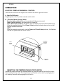
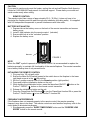
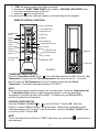
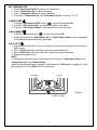
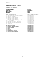
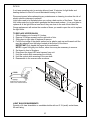
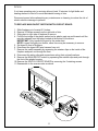
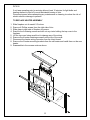
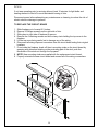
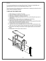
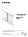
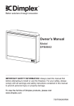
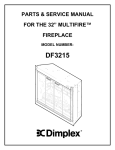
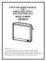
PARTS AND SERVICE MANUAL
FOR
DIMPLEX MULTIFIRE™
ELECTRIC FIREPLACE
MODEL NUMBER:
DF3015
Valued Customer,
We are pleased that you have chosen to purchase an electric fireplace
manufactured by Dimplex North America Ltd.Over the years, valuable
memories will occur around the warmth and comfort of your hearth. Thank you
for allowing our product to be the backdrop for those special moments.
TABLE OF CONTENTS
OPERATION
PAGE 2
PARTS DRAWING
PAGE 7
PARTS LIST
PAGE 8
LOWER LIGHT BULB REPLACEMENT
PAGE 9
UPPER LIGHT BULB REPLACEMENT
PAGE 10
MAIN ON/OFF SWITCH REPLACEMENT
PAGE 11
SWITCH CIRCUIT BOARD REPLACEMENT
PAGE 11
FLAME MOTOR/REFLECTOR ROD REPLACEMENT
PAGE 12
HEATER ASSEMBLY REPLACEMENT
PAGE 13
CIRCUIT BOARD REPLACEMENT
PAGE 14
POWER CORD REPLACEMENT
PAGE 15
1
DF3015
OPERATION
ELECTRIC FIREPLACE MANUAL CONTROL
The manual controls for the fireplace are located in the lower right hand corner.
A. Main On/Off Switch
Supplies power to the 3 position manual control switch.
B. 3 Position Manual Control Switch
Remote (right position): The unit is operated with the remote control.
Flame (center position): The flame effect is turned ON.
Flame & Heat (left position): The flame effect and heater are turned ON simultaneously.
When the manual control is in the Flame & Heat position the heater does not run on the
remote operated thermostat.
NOTE
When the manual control switch is in the Flame and Flame & Heat positions, the fireplace
unit will not operate with the remote control.
3 Position
Manual
Control
Main
On/Off
Switch
Initialization
Button
RESETTING THE TEMPERATURE CUTOFF SWITCH
Should the heater overheat, an automatic switch will turn the heater off and it will not come
back on without being reset. The temperature cutoff switch can be reset by unplugging the
unit, waiting 5 minutes and plugging the unit back in.
2
CAUTION
If you need to continuously reset the heater, unplug the unit and call Dimplex North America
Limited at 1-800-668-6663 and press 4 for technical support. Please have your model and
serial number ready when calling.
REMOTE CONTROL
The remote control has a range of approximately 50 ft. (15.25m), it does not have to be
pointed at the fireplace and can pass through most obstacles (including walls). It is supplied
with 243 independent frequencies to prevent interference with other units.
BATTERY INSTALLATION
1. Depress tab on the battery cover on the back of the remote transmitter and remove
battery cover.
2. Install 2 AAA batteries into the remote control. (included)
3. Ensure child lock is in the “unlocked” position.
4. Replace the battery cover.
Batteries
FIGURE 3
NOTE
When the “BAT” symbol is present on the remote control it is recommended to replace the
batteries promptly, to maintain full functionality of the remote/fireplace. The remote transmitter
has a battery backup time of only several hours.
INITIALIZING THE REMOTE CONTROL
1. Plug cord into 120 volt wall outlet.
2. Ensure the Main On/Off switch located in the switch box on the fireplace in the lower
right hand corner is in the
ON position.
3. Set the 3 position manual control to the Remote position (right position).
4. Press and hold the initialization button on the unit.
5. While holding the initialization button, press the flame/heat ON/OFF
button or the
Purifire™ ON/OFF
button on the remote control transmitter.
6. Release the initialization button on the unit.
7. Press the Flame/Heat On/Off button to turn the Flame/Heat function ON or press the
Purifire™ On/Off button
to turn the Purifire™ function ON.
FREQUENCY INTERFERENCE
If the fireplace does not respond properly to the remote control, the remote operating
frequency may have to be reset. The remote control can send another frequency code to the
circuit board to eliminate interference.
1. Simultaneously press the “SLEEP TIMER DOWN” button and the “PURIFIRE LOW
SPEED” button on the remote control.
3
2. “COD” will appear in place of the sleep timer digits.
3. Release the “SLEEP TIMER DOWN” button and the “PURIFIRE LOW SPEED” button.
4. Press the initialization button on the unit.
5. press the
button on the remote.
Your remote will now have a different frequency communicating with the fireplace.
REMOTE CONTROL FUNCTIONS
Room Temperature
Set Temperature
Temperature
Down
Dimmer
Down
Flame Speed
Down
Sleep Timer
Down
Purifire Low
Speed
Temperature Up
Dimmer Up
Dimmer
Flame Speed Up
Flame Speed Control
Sleep Timer Up
Sleep Timer
Purifire High Speed
Batteries
Purifire
Flame & Heat
On / Off
Purifire On / Off
Child Lock
FIGURE 5
FLAME/HEAT ON/OFF BUTTON
Press the “Flame/Heat On/Off “button
to turn the Flame/Heat function ON. When the “Set
Temperature” is higher then the “Room Temperature” the heat will come on. To turn the
heat off, lower the “Set Temperature” so that it’s setting is lower then the “Room
Temperature”. The default temperature setting is 72°F (22°C).
NOTE
When using the remote control the heater runs on a thermostat. Press the “Temperature Up”
or “Temperature Down” button to adjust the set temperature. Once the desired set
temperature is reached the heater will turn OFF. The heater will cycle ON and OFF to
maintain the desired set temperature.
PURIFIRE ON/OFF BUTTON
Press the “Purifire™ On/Off” button
to turn the Purifire™ function ON. When the
Purifire™ function is ON the Purifire™ symbol will flash. When off the symbol will be solid.
The default setting for the Purifire™ is set at low speed. Press the “Purifire™ On/Off” button
to turn the Purifire™ function OFF.
NOTE
To turn the Flame/Heat and Purifire™ “OFF” at the same time, press both
simultaneously.
4
control buttons
SET TEMPERATURE
1. Press “Flame Heat On/Off” button to turn fireplace on.
2. Press “Temperature Up” to raise thermostat.
3. Press “Temperature Down” to lower thermostat.
4. Press both “Temperature Up” and Temperature Down” to change °F to °C.
FLAME SPEED
1. Press the “Flame/Heat On/Off” button
to turn the Flame/Heat ON.
2. Press the “Flame Speed Up” to increase the speed of the flame.
3. Press the “Flame Speed Down” to decrease the speed of the flame.
LIGHT DIMMER
1. Press the Flame/Heat button
to turn the Flame/Heat ON.
2. Repeatedly press the “Light Dimmer Up” or “Light Dimmer Down” button to decrease
or increase the brightness of the upper lights.
CHILD LOCK
1. Depress tab on the battery cover on the back of the remote transmitter and remove the
battery cover.
2. Move “Child Lock” tab to the right to lock the remote transmitter.
3. Move “Child Lock” tab back to the left to unlock the remote transmitter.
4. Replace the battery cover.
NOTE
To temporarily unlock the remote transmitter press (in order) “Temperature Down” then
“Temperature Up” then “Dimmer Down”.
When the remote transmitter’s backlight is illuminated the “Child Lock” is bypassed. When
the backlight is off the “Child Lock” is re-activated.
Unlocked
Locked
Figure 6
Child Lock Switch
5
PURIFIRE™
The Purifire™ includes a high efficiency filter to help improve the quality of air.
1. Press the
button for the Purifire™ function.
2. Press the “Purifire Low Speed” button or the “Purifire High Speed” button to select
LOW or HIGH.
3. Press the
OFF.
button to turn the Purifire™ ON, press the
button to turn the Purifire™
SLEEP TIMER
The Sleep Timer automatically shuts off the fireplace after a preset time (from 30 minutes to 8
hours).
1. Press the Flame/Heat On/Off button to turn the fireplace ON.
2. To set the sleep timer press the “Sleep Timer Up” button.
3. Set the timer from 30 minutes through 8 hours.
4.
5. The fireplace will automatically turn OFF when the sleep timer reaches 0 minutes.
6. The sleep timer can be cancelled at any time by pressing the “Sleep Timer Down”
button repeatedly until the sleep timer displays “0”.
6
DF3015
2
3
10
13
7
4
8
12
11
1
9
5
6
14
7
15
DF3015
REPLACEMENT PARTS
FIREBOX, 30" - DIMPLEX
CATALOGUE NO.
PART NO.
MOD LEVEL:
MADE IN:
DF3015
6903020159
NONE
CHINA
REPLACEMENT PART
1. 30” URETHANE LOG SET ASSEMBLY
2. HEATER ASSEMBLY
3. UPPER LIGHT HARNESS
4. LOWER LIGHT HARNESS (left and right bulbs)
LOWER LIGHT HARNESS (center bulb)
5. FLAME MOTOR
6. REMOTE CONTROL – SENDER
7. REMOTE CONTROL RECEIVER
8. CORD SET
9. REFLECTOR ROD
10. MIRROR, SEMI-SILVERED
11. FRONT GLASS
12. FOOT
13. FILTER
14. MAIN ON/OFF SWITCH
15. SWITCH CIRCUIT BOARD
REPLACEMENT PART NO.
0439070100RP
2200490600RP
2500400200RP
2500400100RP
2500150200RP
3000240200KIT
3000300100RP
3000300200RP
4100040400RP
5900080700RP
5900680100RP
5900310400RP
8800090100RP
0439060100RP
2800070700RP
3000300300RP
8
DF3015
If unit was operating prior to servicing allow at least 10 minutes for light bulbs and
heating element to cool off to avoid accidental burning of skin.
Disconnect power before attempting any maintenance or cleaning to reduce the risk of
electric shock or damage to persons.
Light bulbs need to be replaced when you notice a dark section of the flame. There are
four bulbs under the log set which generate the flames and embers. It is a good idea to
replace all of the light bulbs at one time if they are close to the end of their rated life.
Group replacement will reduce the number of times you need to open the unit to replace
the light bulbs.
TO REPLACE LOWER BULBS:
1. Slide fireplace out of mantel 2-3 inches.
2. Remove 4 Phillips screws from the right side of trim.
3. Slide glass to right side of fireplace to remove.
4. Pull the front edge of the plastic ember bed or plastic grate up and forward until the
rear tab releases from the ledge located at the bottom of the mirror.
IMPORTANT:Only handle the logset by the emberbed.
NOTE: Logset fits tightly into firebox, some force may be necessary to remove.
5. Set logset in front of fireplace.
6. Disconnect the logset LED wire harness from unit.
7. Hold the socket while unscrewing the old bulb.
8. Hold the socket while screwing in the new bulb.
9. Reassemble in the reverse order as above.
LIGHT BULB REQUIREMENTS
Quantity of 4 clear chandelier or candelabra bulbs with an E-12 (small) socket base,
60 watt rating.
9
DF3015
If unit was operating prior to servicing allow at least 10 minutes for light bulbs and
heating element to cool off to avoid accidental burning of skin.
Disconnect power before attempting any maintenance or cleaning to reduce the risk of
electric shock or damage to persons.
Light bulbs need to be replaced when you notice a dark section of the flame. There are
four bulbs under the log set which generate the flames and embers. It is a good idea to
replace all of the light bulbs at one time if they are close to the end of their rated life.
Group replacement will reduce the number of times you need to open the unit to replace
the light bulbs.
TO REPLACE UPPER BULBS:
1. Slide fireplace out of mantel 2-3 inches.
2. Remove 4 Phillips screws from the right side of trim.
3. Slide glass to right side of fireplace to remove.
4. Pull the front edge of the plastic ember bed or plastic grate up and forward until the
rear tab releases from the ledge located at the bottom of the mirror
IMPORTANT:Only handle the logset by the emberbed.
NOTE: Logset fits tightly into firebox, some force may be necessary to remove.
5. Set logset in front of fireplace.
6. Disconnect the logset LED wire harness from unit.
7. Hold the socket while unscrewing the old bulb.
8. Hold the socket while screwing in the new bulb.
9. Reassemble in the reverse order as above.
LIGHT BULB REQUIREMENTS
Quantity of 4 clear chandelier or candelabra bulbs with an E-12 (small) socket base,
60 watt rating.
10
DF3015
If unit was operating prior to servicing allow at least 10 minutes for light bulbs and
heating element to cool off to avoid accidental burning of skin.
Disconnect power before attempting any maintenance or cleaning to reduce the risk of
electric shock or damage to persons.
TO REPLACE MAIN ON/OFF SWITCH/SWITCH CIRCUIT BOARD
1.
2.
3.
4.
Slide fireplace out of mantel 2-3 inches.
Remove 4 Phillips screws from the right side of trim.
Slide glass to right side of fireplace to remove.
Pull the front edge of the plastic ember bed or plastic grate up and forward until the
rear tab releases from the ledge located at the bottom of the mirror.
IMPORTANT: Only handle the logset by the ember bed.
NOTE: Logset fits tightly into firebox, some force may be necessary to remove.
5. Set logset in front of fireplace.
6. Disconnect the logset LED wire harness from unit.
7. Remove the switch assembly by squeezing the retainer clips on the inside of the
fireplace and push out through the front
8. Disconnect the wiring clips and connections noting their original locations.
9. Remove the MAIN ON/ OFF switch by squeezing the retainer clips and push through
the font of the plastic housing.
10. Remove the SWITCH CIRCUIT BOARD by removing the 2 retaining screws.
11. Reassemble in the reverse order as above.
11
DF3015
If unit was operating prior to servicing allow at least 10 minutes for light bulbs and
heating element to cool off to avoid accidental burning of skin.
Disconnect power before attempting any maintenance or cleaning to reduce the risk of
electric shock or damage to persons.
TO REPLACE FLAME MOTOR/REFLECTOR ROD
1.
2.
3.
4.
Slide fireplace out of mantel 2-3 inches.
Remove 4 Phillips screws from the right side of trim.
Slide glass to right side of fireplace to remove.
Pull the front edge of the plastic ember bed or plastic grate up and forward until the
rear tab releases from the ledge located at the bottom of the mirror.
IMPORTANT: Only handle the logset by the ember bed.
NOTE: Logset fits tightly into firebox, some force may be necessary to remove.
5. Set logset in front of fireplace.
6. Disconnect the logset LED wire harness from unit.
7. Disconnect the flicker motor wiring connector from the circuit board.
8. Remove the reflector rod from the flicker motor by pulling the end of the rod to the
left and cut the reflector spring with wire cutters. DO NOT TAKE THE LEFTOVER
SPRING OFF THE END OF THE REFLECTOR ROD
9. Remove the (2) screws securing the flicker motor to the flicker motor bracket.
10. Discard the old flicker motor.
11. Pick up the 1 ½” rubber sleeve and locate over remaining spring on reflector rod.
ENSURE TO LOCATE THE LARGE OPENING OF THE RUBBER SLEEVE OVER
THE REMAINING SPRING OF THE REFLECTOR ROD.
12. Reassemble in the reverse order as above.
12
DF3015
If unit was operating prior to servicing allow at least 10 minutes for light bulbs and
heating element to cool off to avoid accidental burning of skin.
Disconnect power before attempting any maintenance or cleaning to reduce the risk of
electric shock or damage to persons.
TO REPLACE HEATER ASSEMBLY
1.
2.
3.
4.
5.
6.
7.
8.
9.
Slide fireplace out of mantel 2-3 inches.
Remove 4 Phillips screws from the right side of trim.
Slide glass to right side of fireplace to remove.
Remove the 6 retaining screws and drill out any rivets holding the top cover to the
fireplace.
Lift the top cover being careful not to damage any of the wiring.
Remove the 4 heater retaining screws from the top of the cover.
Disconnect the heater wiring connector from the circuit board.
Remove the 2 heater mounting brackets from the old heater and install them on the new
heater.
Reassemble in the reverse order as above.
13
DF3015
If unit was operating prior to servicing allow at least 10 minutes for light bulbs and
heating element to cool off to avoid accidental burning of skin.
Disconnect power before attempting any maintenance or cleaning to reduce the risk of
electric shock or damage to persons.
TO REPLACE THE CIRCUIT BOARD
1.
2.
3.
4.
5.
6.
7.
8.
9.
Slide fireplace out of mantel 2-3 inches.
Remove 4 Phillips screws from the right side of trim.
Slide glass to right side of fireplace to remove.
Remove the 6 retaining screws and drill out any rivets holding the top cover to the
fireplace.
Lift the top cover being careful not to damage any of the wiring.
Disconnect all wiring clips and connectors from the circuit board noting their original
locations.
From inside the fireplace, break off the six mounting studs on the circuit board by
grasping with pliers and twisting on the protruding part of the stud, push the
remainder of the studs out through the top panel.
NOTE: New mounting studs are supplied with the replacement circuit board.
Properly orientate the new circuit board and connect all of the wiring connections
14
DF3015
If unit was operating prior to servicing allow at least 10 minutes for light bulbs and
heating element to cool off to avoid accidental burning of skin.
Disconnect power before attempting any maintenance or cleaning to reduce the risk of
electric shock or damage to persons.
TO REPLACE THE POWER CORD
1.
2.
3.
4.
Slide fireplace out of mantel 2-3 inches.
Remove 4 Phillips screws from the right side of trim.
Slide glass to right side of fireplace to remove.
Remove the 6 retaining screws and drill out any rivets holding the top cover to
the fireplace.
5. Lift the top cover being careful not to damage any of the wiring
6. Disconnect the power cord wires from the circuit board.
7. With needle nose pliers grasp the power cord strain relief grommet from inside
the rear panel and push while twisting to remove.
8. Pull the power cord out through the hole in the rear cover.
9. Install the new cord set through the hole in the rear cover by placing the strain
relief over the cord, hold the strain relief with pliers and slide into mounting hole.
10. Connect all of the wiring connections in their original locations on the terminal
block.
11. Reassemble in the reverse order as above.
15