1
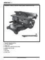
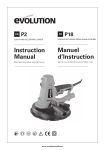
RAGE 6
255mm (10”) Compound
Mitre / Table Saw
Instruction
Manual
Read instructions before operating this tool.
30 11 10 V1
www.evolutionbuild.com
G09100
EC - DECLARATION OF CONFORMITY
EC - DECLARATION OF CONFORMITY
We, the importer
TABLE OF CONTENTS
EC - Declaration of Conformity
Important Information
12 Month Limited Warranty
General Safety Rules
Additional Specific Safety Rules
Labels and Symbols
4
Evolution Power Tools Ltd.
Venture One
Sheffield
S20 3FR
6
Declare that the product
8
Part numbers: EVOLUTION RAGE 6
Evolution: TABLE MITRE SAW
2
7
9
Specification10
Machine Overview
11
Operation Mitre Saw
Operation Table Saw
14
16
Maintenance18
Environmental Protection
25
Service Parts Lists25
Complies with the essential requirements
of the following European Directives:
2006/42/EC – Machine Directive
2006/95/EC – Low Voltage Directive
2004/108/EC – EMC Directive
2002/95/EC – Restriction of the use of
Certain Hazardous Substances in Electrical
and Electric Equipment
Standards and Technical
specifications referred to:
EN 61000-6-3:2007
EN 55014-1:2006
EN 55014-2+A2:2008
EN 60745-1:2009
EN 60745-2-11+A12:2009
All documentation is held on file at the
above address and is available, on request
for review.
Authorized Signatory
Date: 29/8/2010
Name: Mr Matthew J Gavins
Position: Managing Director
Year of Manufacture: 2010
2
www.evolutionbuild.com
RAGE 6
FIG 1
FIG 2
FIG 3
FIG 4
FIG 5
FIG 6
FIG 7
FIG 8
FIG 9
www.evolutionbuild.com
3
4
FIG 10
FIG 11
FIG 12
FIG 13
FIG 14
FIG 15
FIG 16
FIG 17
FIG 18
www.evolutionbuild.com
RAGE 6
FIG 19
FIG 20
FIG 21
FIG 22
FIG 23
FIG 24
FIG 25
FIG 26
FIG 27
www.evolutionbuild.com
5
EVOLUTION RAGE 6 255mm COMPOUND
MITRE/TABLE SAW
head office, or call the appropriate Helpline
number.
Congratulations on your purchase of an
Evolution Power Tool’s Rage 6 Compound
Mitre/Table Saw.
Please complete your
product registration on line to validate your
machine’s warranty period and ensure prompt
service if needed. We sincerely thank you for
selecting a product from Evolution Power
Tools.
IMPORTANT SAFETY INSTRUCTIONS
To reduce the risk of electric shock, this
equipment is fitted with an approved cord and
plug for its intended country of use. Do not
change the cord or plug in any way.
GENERAL SAFETY RULES
Read and understand all instructions before
operating this product. Failure to follow all
instructions listed below may result in electric
shock, fire and / or serious personal injury.
SAVE THESE INSTRUCTIONS FOR FUTURE
REFERENCE.
12 MONTH LIMITED WARRANTY. Evolution
Power Tools reserves the right to make
improvements and modifications to design
without prior notice.
Evolution Power Tools will, within twelve (12)
months from the original date of purchase,
repair or replace any goods found to be
defective in materials or workmanship. This
warranty is void if the tool being returned
has been used to cut materials beyond
the recommendations in the Instruction
Manual or if the saw has been damaged by
accident, neglect, or improper service. This
warranty does not apply to machines and
/ or components which have been altered,
changed, or modified in any way, or subjected
to use beyond recommended capacities
and specifications. Electrical components
are subject to respective manufacturers’
warranties. All goods returned defective
shall be returned prepaid freight to Evolution
Power Tools. Evolution Power Tools reserves
the right to optionally repair or replace it with
the same or equivalent item. There is no
warranty – written or verbal – for saw blades.
In no event shall Evolution Power Tools be
liable for loss or damage resulting directly or
indirectly from the use of our merchandise or
from any other cause. Evolution Power Tools
is not liable for any costs incurred on such
goods or consequential damages. No officer,
employee or agent of Evolution Power Tools
is authorised to make oral representations of
fitness or to waive any of the foregoing terms
of sale and none shall be binding on Evolution
Power Tools. Questions relating to this limited
warranty should be directed to the company’s
6
Read all these instructions before attempting to
operate this product and save these instructions.
The term “power tool” in the warnings refers
to your mains-operated (corded) power tool or
battery-operated (cordless) power tool.
WARNING: When using electric tools, basic
safety precautions should always be followed to
reduce the risk of fire, electric shock and personal
injury.
Please read all of these instructions before
attempting to operate this machine. Save this
manual for future reference.
1. Keep work area clear. Cluttered work areas
invite accidents.
2. Consider work area environment. Do not
expose tools to rain. Do not use tools in damp or
wet locations. Keep work area well lit. Never use
tools near flammable liquids or gases.
3. Protect yourself against electric shock. Avoid
body contact with earthed or grounded surfaces.
4. Keep other people away. Do not let others,
especially children, come close to the work, and
touch the tool or the extension lead. Keep them
away from the work area.
5. Store idle tools. When not in use, tools should
be stored in a dry locked-up place, out of children’s
reach.
6. Never force the tools. Your tools will be more
efficient and safer when used at the rate for which
they were intended.
www.evolutionbuild.com
RAGE 6
7. Use the right tool. Do not force small tools to
do the job of a heavy duty tool. Do not use tools
for purposes not intended; for example do not use
circular saws to cut tree limbs or logs.
8. Dress properly. Do not wear loose clothing
or jewellery which may get caught in moving
parts. Non-skid footwear is recommended when
working outdoors. If you have long hair, tie it back
and wear protective hair covering.
9. Use protective equipment. Use safety glasses.
Use face or dust mask if cutting operations create
dust.
10. Connect dust extraction equipment. If the
machines have a connection for dust extraction
equipment, ensure these are connected and
properly used.
11. Do not damage the cable. Never pull the
power cable to disconnect the machine. Keep the
cable away from heat, oil and sharp edges.
12. Secure workpiece. Where possible, use
clamps or a vice to hold the workpiece. It’s much
safer than using your hands.
13. Don’t over reach. Keep proper footing and
balance at all times.
14. Maintain tools in good working
condition. Keep cutting tools sharp and clean
for better performance and optimum safety.
Follow instructions for lubricating and changing
accessories. Inspect power cables regularly and,
if damaged, have them replaced by an authorised
service centre. Inspect extension cables regularly
and replace immediately if damaged. Keep
handles dry, clean and free from oil and grease at
all times.
15. Disconnect tools. Disconnect tools from
the power supply when not in use, before any
maintenance operation and when changing
accessories such as blades, bits, cutters, etc.
16. Remove adjusting keys and spanners. Get
into the habit of checking that adjusting keys and
spanners have been removed from the machine
before turning it on.
17. Avoid unintentional starting. Ensure switch
is in “off” position before plugging in the machine.
18. Use proper extension leads. When the tool is
used outdoors, use only extension leads intended
for outdoor use and labelled as such.
19. Stay alert. Concentrate on what you are
doing, use common sense and do not operate the
tool when you are tired.
20. Check that no part is damaged. Before
using a tool, make sure that it is in good working
order. Check the alignment and condition of
moving parts, mounting and any other aspect
that may affect its operation. A guard or other
part that is damaged should be properly repaired
or replaced by an authorised service centre
unless otherwise indicated in this instruction
manual. Do not use the tool if the switch does
not turn on and off.
21. WARNING. The use of any accessory or
attachment other than one recommended in
this instruction manual may present a risk of
personal injury.
22. Have your tool repaired at an authorised
service centre. This electric tool complies with
current safety rules. Repairs should only be
carried out by an authorised service centre using
original spare parts. Failing this, the user could
expose themselves to considerable danger.
HEALTH ADVICE
WARNING: When drilling, sanding, sawing
or grinding, dust particles will be produced. In
some instances, depending on the materials you
are working with, this dust can be particularly
harmful to you (e.g. lead from old gloss paint).
You are advised to consider the risks associated
with the materials you are working with and to
reduce the risk of exposure.
You should:
-Work in a well-ventilated area.
-Work with approved safety equipment, such as
dust masks that are specially designed to filter
microscopic particles.
ADDITIONAL SAFETY INSTRUCTIONS FOR
YOUR MITRE SAW
WARNING: Be sure to read and understand
all instructions. Failure to follow all instructions
listed below may result in electric shock, fire
and/or serious personal injury.
1. Know your power tool. Read operator’s
manual carefully. Learn the applications and
limitations, as well as the specific potential
hazards related to this tool.
2. Always wear safety glasses or eye
shields when using this mitre saw. Everyday
eyeglasses have only impact-resistant lenses;
they are not safety glasses.
www.evolutionbuild.com
7
3. Always protect your lungs. Wear a face
mask or dust mask if the operation is dusty.
4. Always protect your hearing. Wear hearing
protection during extended periods of operation.
5. Inspect the machines power cord regularly
and if damaged have it repaired or replaced.
Always be aware of the cords location.
6. Always check for damaged parts. Before
further use of the tool, a guard or other part
that is damaged should be carefully checked to
determine if it will operate properly and perform
its intended function. Check for misalignment or
binding of moving parts, breakage of parts, and
any other condition that may affect the tool’s
operation. A guard or other part that is damaged
should be properly repaired or replaced at a
qualified service centre. Keep guards in place
and in working order.
7. Do not abuse the cord. Never use the
cord to carry the tool or pull the plug from the
outlet. Keep cord away from heat, oil, sharp
edges or moving parts. Replace damaged cords
immediately. Damaged cords increase the risk
of electric shock.
8. Always make sure that your extension
cord is in good condition. When using an
extension cord be sure to use one that is heavy
enough to carry the current that your tool will
draw. An undersized cord will cause a drop in
line voltage, resulting in loss of power and
overheating.
9. Do not use the tool while tired or under the
influence of drugs, alcohol or any medication.
Following this rule will reduce the risk of electric
shock, fire or serious personal injury.
10. Save these instructions. Refer to them
frequently and use them to instruct others who
may use this tool. If someone borrows this tool,
make sure they have these instructions also.
11. When the correct blade to cut the material
has been fitted, this saw is recommended for
cutting steel and ferrous metals, aluminium
and non-ferrous metals, wood, and plastic
only.
12. Do not use saw blades with High Speed
Steel (HSS) or blades that are damaged or
deformed.
13. Replace the table insert when worn.
8
14. Use only saw blades recommended by the
manufacturer and which are the exact bore
and diameter required for this machine.
15. Connect your mitre saw to a dust collecting
device (I.D.Ø32mm) when sawing material
likely to cause dust.
16. Select saw blades in relation to the
material to be cut. Use only genuine Evolution
or Evolution recommended accessories.
17. Check the maximum depth of cut.
18. When sawing long work pieces, always
use extra support to provide better support,
and use clamps or other clamping devices. To
reduce the risk of injury, return the slide carriage
to the full rear position after each crosscut
operation.
19. The operator is adequately trained in the
use adjustment and operation and operation
of the machine.
20. Provide for adequate room lighting at
your workplace or for adequate lighting of the
immediate work area.
21. When fitted with a laser no exchange
with a different type of laser is permissible.
Repairs shall only be carried out by the laser
manufacturer or an authorised agent.
22. Refrain from removing any cut-offs or other
parts of the workpiece from the cutting area
whilst the machine is running and the saw
head is not in the rest position. Never reach
around the saw blade. Turn off tool and wait for
saw blade to stop before moving workpiece or
changing settings.
23. Never stand on this tool. Serious injuries
could occur if this tool tips over and you come
into contact with the saw blade.
24. Reduce the risk of unintentional starting.
Make sure switch is in off position before
plugging in.
WARNING: the operation of any mitre saw can
result in foreign objects being thrown into your
eyes, which can result in severe eye damage.
Before beginning power tool operation, always
wear safety goggles or safety glasses with side
shield and a full face shield when needed.
www.evolutionbuild.com
RAGE 6
WARNING: If any parts are missing, do not
operate your mitre saw until the missing parts
are replaced. Failure to follow this rule could
result in serious personal injury.
SAFETY LABELS & SYMBOLS
WARNING: Do not operate machine if warning and
/ or instruction labels are missing or damaged. Contact
Evolution Power Tools for replacement labels.
CARRYING YOUR MITRE SAW
Safety Advice
1. Although compact, this saw is heavy. To
reduce the risk of back injury, get competent
help whenever you have to lift the saw.
2. To reduce the risk of back injury, hold the tool
close to your body when lifting. Bending your
knees so you can lift with your legs, not your
back. Lift by using the handhold areas at each
side of the bottom of the base.
3. Never carry the table mitre saw by the power
cord or the trigger grip of the handle. Carrying
the tool by the power cord could cause damage
to the insulation or the wire connections
resulting in electric shock or fire.
4. Before moving the saw tighten the mitre
and bevel lock knobs to guard against sudden
movement.
5. Lock the cutting head in its lowest position.
Ensure that the cutting head locking pin is
completely engaged in its socket.
WARNING: Do not use the blade guard as a
‘lifting point’. The power cord must be removed
from the power supply before attempting to move
the machine.
• Lock down the head using the head locking pin.
• Loosen the mitre angle lock knob. Push down the
mitre angle lever and rotate the table to either of its
maximum settings.
• Lock the table in position using the locking knob.
• Use the two carry handle cut-outs machined
into either end of the machine base, to transport
the machine.
Only use genuine Evolution replacement saw
blades. Unauthorized blades may be dangerous!
Keep saw blades securely fastened. Check the
blade flanges for debris before installing any
new blade. Do not use dull, broken or damaged
blades. Check the blade regularly for condition
and wear. A damaged or worn blade should be
replaced immediately. Beware of ejecting chips
as they may be HOT. Always make provision
for the safe handling of excess material. Keep
machine base and rotary table free from dirt and
other debris.
To obtain an additional copy of your manual,
please contact Evolution Power Tools at:
UK 0870 609 2297
WEBwww.evolutionpowertools.com
Symbol
Description
V
Volts
A
Amperes
Hz
Hertz
Min
Speed
~
Alternating Current
no
No Load Speed
-1
Place the saw on a secure stationary work
surface and check the saw over carefully.
Check particularly the operation of all the
machines safety features before commissioning
or operating the machine.
www.evolutionbuild.com
Wear Safety
Goggles
Wear Ear Protection
Do Not Touch
Wear Dust Protection
Restriction
of Hazardous
Substances Directive
CE certification
Waste electrical and
electronic equipment
9
RAGE 6 TABLE MITRE SAW
SPECIFICATION
Designed to cut:
Wood – Max section 75mm x 300mm
Aluminium
Plastic
The declared vibration total value has been
measured in accordance with a standard
test method and may be used for comparing
one tool with another.
The declared vibration total value may also
be used in a preliminary assessment of
exposure.
Technical Data
WARNING: The vibration emission during
Motor (230v ~ or 110v ~ 50/60 Hz)
actual use of the power tool can differ from
(Watts): 1600W
the declared total value depending on the
RPM No Load (min-1): 2500
ways in which the tool is used. The need
Recommended Maximum Duty Cycle
to identify safety measures and to protect
(Minutes): 30 mins
the operator are based on an estimation
of exposure in the actual conditions of use
Weight:
(taking account of all parts of the operating
17.85Kg
cycle, such as the times the tool is switched
off, when it is running idle, in addition to
Blade Dimensions
trigger time).
Diameter: (10”) 255mm
Supplied Accessories
Number of Teeth: 28
Bore Diameter 25.4mm
DESCRIPTIONQUANTITY
Thickness: 2mm
Instruction Manual
1
Hold Down Clamp
1
Maximum Cutting Capacity (Wood) Mitre
Push Stick
1
Saw Configuration
Allen Key (Arbor Lock)
1
At 900 mitre x 900 bevel
Allen Key (Blade Change)
1
120mm x 70mm
Multi-Purpose Blade (Fitted)
1
At 450 mitre x 900 bevel
Rip Fence (Fitted)
1
90mm x 70mm
Auxiliary Lower Blade Guard
1
At 450 mitre x 450 bevel
50mm x 50mm
Additional Accessories
In addition to the standard accessories
Maximum Cutting Capacity Table Saw
supplied with this machine, other
Configuration. Maximum cutting depth;
accessories are available to improve its
performance, these include the following
Wood 50mm
items:
Steel 6mm
Aluminium 6mm
1. Dust Bag – the design of this machine
allows for a dust bag or workshop vacuum
Noise and Vibration Data
extraction device to be fitted to the rear of
Sound pressure level:
the machine.
106.3dB(A) K=3dB(A)
2. Specialist cutting blades – use only
Sound power level:
Evolution Blades with this machine.
119.3dB(A) K=3dB(A)
Vibration level:
Additional accessories can be obtained by
2.5 m/s2 K =1.5dB(A)
contacting your local dealer (or Evolution
Power Tools).
10
www.evolutionbuild.com
RAGE 6
OVERALL VIEW OF RAGE 6 MITRE SAW CONFIGURATION
6
1
3
7
5
9
13
4
12
8
11
14
2
10
1. ON/OFF TRIGGER SWITCH
9. BEVEL ANGLE LOCKING LEVER
2. CUTTING HEAD LOCKING PIN
10. MITRE ANGLE SCALE
3. CUTTING HANDLE
11. POSITIVE STOP LOCKING LEVER
4. ROTARY TABLE
12. FENCE
5. LOWER BLADE GUARD
13. HOLD DOWN CLAMP
6. UPPER BLADE GUARD
14. MOUNTING HOLE
7. BLADE
8. MITRE LOCK KNOB
www.evolutionbuild.com
11
OVERALL VIEW OF RAGE 6 TABLE SAW CONFIGURATION
5
7
3
6
1
4
2
8
1. ON/OFF TRIGGER SWITCH
2. CUTTING HANDLE
3. TABLE TOP
4. AUXILLIARY LOWER BLADE GUARD
5. UPPER BLADE GUARD
6. BLADE
7. RIP FENCE
8. PUSH STICK
12
www.evolutionbuild.com
RAGE 6
GETTING STARTED
CAUTION! ALWAYS DISCONNECT THE
SAW FROM THE POWER SOURCE
BEFORE MAKING ANY ADJUSTMENTS.
Refer to the “Service Parts List Drawing”.
Install a blade as detailed in the “Installing or
Removing the Blade” section.
1. Mounting the Table Mitre Saw
WARNING: To reduce the risk of injury from
unexpected saw movement, place the saw
in the desired location either on a workbench
or other recommended leg set. The base of
the saw has four holes to mount the mitre
saw. If the saw is to be used in one location,
permanently fasten it to the workbench
or leg set using appropriate bolts with lock
washers and nuts.
1. Tighten the mitre and bevel locks.
2. Position the saw so other people cannot
stand behind it. Thrown debris could injure
people in its path.
3. Place the saw on a firm, level surface
where there is plenty of room for handling
and properly supporting the workpiece.
4. Support the saw so that the table is level
and the saw does not rock.
5. Bolt or clamp the saw to its support.
2. Installing or Removing the Blade
WARNING: Only use genuine Evolution
blades which are designed for this machine.
Ensure that the maximum speed of the
blade is compatible with the machine. Only
perform this operation with the machine
disconnected from the mains supply.
Note: It is recommended that the operator
considers wearing protective gloves when
handling the blade during installation or when
changing the machines blade.
1. Pull out the cutting head locking pin and
allow the cutting head to rise to its upper
position. (Fig. 1)
2. Remove the top blade guard with the
attached riving knife by loosening the socket
headed fixing screw (Fig. 2) and withdrawing
the riving knife upwards. The riving knife is
slotted for easy removal.
3. Push in the sprung loaded lower guard
operating pawl and slide it upwards along
the slot. The lower guard will rotate into the
machine exposing the blade. (Fig. 3)
4. Insert the supplied hex key into the rear
labeled arbor access port (Fig. 4) Ensure that
the hex key engages completely into the arbor
socket. Hold the hex key firmly so that the
machine arbor cannot rotate.
5. Using the supplied Blade Change Allen Key,
release the blade arbor screw and remove the
outer blade flange and the blade. (Fig. 4 & 5)
Note: The arbor screw has a LH thread.
6. Install the new 255 mm (10”) blade by
guiding it down through the table slot. Make
sure the rotation arrow on the blade matches
the clockwise rotation arrow on the upper
guard. (Fig. 6)
Note: The blade teeth should always point
downward at the front of the saw. Be careful
and patient, the blade is a very precise fit within
the machine. Sometimes extra clearance when
installing a new blade could be useful. If this is
the case raise the table height of the machine
as detailed in Operating Instructions – Table
Saw Configuration – 2 Adjusting the Table
Height.
7. Install the outer blade flange and arbor
screw. Ensure that the outer blade flange lugs
completely engage into the drive flats machined
on the machine arbor.
8. Whilst preventing the arbor from rotating
tighten the arbor screw using moderate force,
but do not overtighten.
9. Return the lower guard to the ‘safe’ position
by sliding the sprung loaded operating pawl
downwards along the slot until it locks in its
operating position.
10. Alternatively lower and cutting head to
its lowest position. The lower guard should
return automatically to its operating position
with the operating pawl correctly deployed.
11. Reinstall the riving knife and top blade
guard. Check that the riving knife is close to,
but does not foul, the saw blades teeth.
www.evolutionbuild.com
13
12. Ensure the both Allen Keys are removed
and the machine arbor rotates freely.
13. Ensure the blade guards are fully
functional before using the machine.
Note: Spacers and spindle rings should not
be used with this machine and/or blade.
3. Debris collection bag (Optional Accessory)
The Debris Collection Bag should be attached
at the debris extraction port.
1. Slide the frame of the collection bag on to
the outlet of the extraction port, ensuring that it
is firmly connected.
2. To release the bag, slide the frame in the
opposite direction.
Note: To ensure optimal dust collection, empty
the dust bag when it becomes approximately
2/3 full.
WARNING: Before cutting metal materials, the
collection bag should be removed and replaced
with a blanking plug (not supplied).
Reinstate the dust bag when cutting wood.
4. Fitting the Hold Down Clamp (Fig. 7)
Two sockets (one either side) are incorporated
into the rear of the machines fence.
1. Fit the clamp to the retaining socket that
best suits the cutting application, ensuring that
it is fully pushed down.
2. Tighten the fence thumbscrew to lock the
pillar into the socket.
3. Put the workpiece to be cut onto the saw
rotary table.
4. Adjust the clamp using the thumbscrew
and hand-wheel so that it securely holds the
workpiece to the saw table. Ensure that the
clamp does not foul the blade or any other
moving machine parts.
Note: It is important that the operator is
adequately trained in the use, adjustment
and operation of the machine and has read
this instruction and safety manual before
commencing operations.
Warning: To reduce the risk of injury,
always unplug the saw before changing or
adjusting any of the machines parts. Compare
the direction of rotation arrow on the guard to
direction arrow on the blade. The blade teeth
should always point downward at the front
of the saw. Check the tightness of the arbor
screw.
In mitre saw configuration the lower auxiliary
guard should be removed from the machine
and safely stored for future use.
The upper blade guard must be secured
to the riving knife using the sprung loaded
locating pin.
The table should be adjusted so that it is in
its upper most position. See section 2 Table
Saw Configuration for adjusting procedure.
In this position the upper blade guard will be
effectively locked down over the crown of
the blade.
1. Releasing the saw head
a) Gently press down on the cutting handle.
b) Pull out the head stop latching knob and
allow the head to rise to its upper position.
(Fig. 8)
Note: The cutting head will automatically
lock in the upper position.
We recommend that when the machine is
not in use the cutting head is locked in its
down position, and the latching knob fully
engaged in its socket.
OPERATING INSTRUCTIONS MITRE SAW CONFIGURATION
Disconnect the Table Mitre Saw from the
mains supply and inspect your Saw before
each use.
14
www.evolutionbuild.com
RAGE 6
2. Preparing to make a cut
a) Avoid awkward operations and hand
positions where a sudden slip could cause
fingers or hands to move into the blade.
b) Cut only one workpiece at a time.
c) Clear everything except the workpiece and
related support devices away from the blade
before turning the mitre saw on.
d) Secure workpiece using clamps to hold
the workpiece securely.
3. Body and Hand Position
1. Never place hands near the cutting area and
keep hands away from the path of blade.
2. Hold the workpiece firmly to the fence to
prevent movement. Use a clamp if necessary
but check that it is positioned so that it does
not foul the blade.
3. Before making a cut. Make a dry run with the
power off so you can see the path of the blade.
4. Keep hands in position until the ON/OFF
trigger has been released and the blade has
completely stopped.
4. On/Off Switch Operation
The On/Off switch is located in the cutting
handle (Fig. 9) and incorporates several safety
features to guard against accidental actuation.
To switch ‘On’
• Grasp the saw handle.
• Slide the trigger switch safety locking slide
downwards.
• Press the trigger switch. The machine will start.
To release the lower safety guard and cutting
head, press the head release thumb button on
the top of the saw handle. (Fig. 10)
Gently lower the cutting head through the
workpiece to make a cut.
To switch ‘Off’
• Allow the cutiing head to rise to its upper
position.
• Release the trigger switch, thumb button and
safety locking slide.
• Wait for the saw blade to completely stop
before removing your hand from the cutting
handle.
The safety locking slide and head release
button will automatically deploy to ‘safety
mode’.
5. Chop Cutting
The saw handle is gently pushed down to cut
through a workpiece.
a) Place the workpiece on the table and
against the fence in the desired position.
Secure with clamps if necessary.
b) Grasp the saw handle.
c) Turn on the saw using the trigger switch
and allow the blade to reach full operating
speed.
d) Press the cutting head release button to
release the saw head.
e) Gently push the saw head down and cut
through the workpiece.
f) After the cut is completed, turn off the saw
by releasing the trigger switch, and allow
the blade to come to a complete halt before
removing your hands or the workpiece from
the machine.
6. Mitre Cutting.
Any angle from 500 left to 500 right is
available, and a protractor scale can be found
on the front of the machine table.
Positive stops are provided at 00 and 150,
22.50, 300 and 450 to the RH and LH side.
a) Loosen the mitre angle locking screw. This
is situated on the RH side of the machine
table just above the 22.50 index mark.
b) Push down the positive stop locking lever
and turn the table to the desired angle as
indicated on the mitre protractor scale by
using the cutting handle. Lock in the required
position by tightening the mitre angle locking
screw. (Fig. 11) A small index pointer can be
found under the table insert to aid accurate
setting.
c) If utilizing the positive stop facility it is still good
practice to lock the table into position using the
mitre locking screw
d) Start the saw and allow it to reach full operating
speed before making the cut.
www.evolutionbuild.com
15
7. Bevel Cutting
The cutting head can be set at any angle up to a
450 to the LH side only.
The bevel angle locking lever is found at the rear
of the machine and a protractor guide and pointer
is incorporated into the casting to the front of the
locking lever to aid setting. (Fig. 12)
a) Loosen the bevel lock lever.
b) Tilt the saw head to the desired angle. Use the
protractor guide provided to the front of the lever
to aid setting.
c) Ensure the locking lever is tightened securely
when the required angle has been achieved.
d) Stand to the left hand side of the handle to
make the cut.
8. Compound Cutting
A compound cut is a combination of a mitre cut
and a bevel cut.
a) Select the required mitre angle as previously
described.
b) Select the required bevel angle as previously
described.
c) Ensure the tightness of all adjustment/locking
screws before making a cut.
9. Cutting Bowed Material
Before cutting any workpiece, check to see if it
is bowed. If it is bowed the workpiece must be
positioned and cut as shown. (Fig. 13 & Fig. 14)
Do not position the workpiece incorrectly or cut
the workpiece without the support of the fence.
10. Clearing Jammed Material
1. Turn mitre saw “OFF” by releasing the trigger
switch.
2. Allow the blade to come to a complete halt
and the cutting to rise to its upper position if
possible.
3. Unplug the mitre saw from the mains
supply.
4. Carefully remove any jammed material
from the unit.
16
11. Supporting Long Workpieces
The free end of a long workpiece should
be supported at the same height as the
machines rotary table. The operator should
consider using a remote workpiece support
stand or enlisting competent trained help if
thought necessary.
OPERATING INSTRUCTIONS –
TABLE SAW CONFIGURATION
WARNING: To operate as a table saw certain
adjustments/checks must be carried out
to ensure that the machine is configured
correctly. Optimally the table saw is best
suited to the Rip Cutting of sheet material.
•The cutting head must be in the locked
down position with the locking pin completely
engaged in its socket.
•The rotary table should be set at 00 and
locked in position with the mitre locking
screw.
•The cutting head should be locked at 00
bevel with the bevel locking lever securely
tightened.
•The auxiliary lower blade guard must be
fitted.
Note: Ensure that these checks/adjustments
are carried out with the machine disconnected
from the mains supply.
1. Fitting the Auxiliary Lower Blade Guard
1. Ensure that the cutting head is in its upper
position.
2. Position the lower auxiliary guard over
the rotary table insert and slide it to the rear.
Narrow end of the guard to the rear, open
wide end to the front.
3. Ensure that the RH and LH sides of the
guard engage with their respective locating
pins on the lower rear fixed blade guard, and
that the cut out slot on the RH side of the
auxiliary guard straddles the machine fence.
(Fig. 15)
4. When satisfied that the lower auxiliary
guard is correctly positioned, lower the
cutting head to its lowest position and
securely lock in place with the locking pin.
www.evolutionbuild.com
RAGE 6
5. Check the integrity of the installation, and
that the machine handle has trapped the
auxiliary guard in place. (Fig. 16)
Warning: The Auxiliary Blade Guard must
be fitted when this machine is used as a
Table Saw. Do not operate this machine if the
Auxiliary Blade Guard is damaged or missing.
2. Adjusting the Table Height
The height of the machine table top above
the machine motor can be adjusted. This
enables your Evolution Table/Mitre Saw to
mimic the rise and fall facility found on many
conventional table saws. The cutting depth
of the blade can thereby be adjusted from
0mm to 50mm.
WARNING: Only adjust the height of the
table with the machine disconnected from
the mains power supply.
To adjust:
• Loosen the two table pillar wing nuts, one
to the front, and one to the rear underneath
the machine table. (Fig. 17)
• Turn the height adjustment screw (Fig. 18)
clockwise or counter-clockwise until the saw
blade protrudes through the table by the
required amount.
• Tighten the two table pillar wing nuts
securely.
Note: The upper blade guard can be rotated
backwards to allow access to the table top so
that a machinist ruler can be used to measure
the height of the blade above the table.
To gain access –
• Pull out the sprung loaded locating pin at
the rear of the upper guard (Fig. 19)
• Rotate the guard backwards.
WARNING: Always return the guard to its
operational position with the locating pin fully
engaged in its hole in the riving knife when
measuring has been completed.
Never use the machine without the upper
guard in its operational position. Check the
operation of the upper guard after every
adjustment.
Return the table to its original (lowest)
position when cutting is completed.
3. The Rip Fence
An adjustable Rip Fence is positioned to the
RH side of the blade. The Rip Fence can be
locked into the desired position by tightening
a wing nut found underneath the Rip Fence
Carrier. (Fig. 20)
The Rip Fence rail is an integral part of the
machine table and contains a measurement
scale to aid setting.
Do not position the Rip Fence to the LH side
of the blade.
Forwards and backwards adjustment of the
rip fence is possible. Loosen the two socket
headed screws with a suitable Allen key and
slide the aluminium extrusion to the desired
position. Tighten the socket screws firmly.
(Fig. 21)
Note: We recommend that normally the
rip fence be adjusted so that the rear of
the guide is level with the rear of the blade
where it emerges from the table.
The aluminium fence guide can be attached
to the fence carrier in a ‘Hi’ and a ‘Lo’ position.
The ‘normal’ and factory supplied position is
with the fence set to the ‘Hi’ setting.
The ‘Lo’ setting can be useful when cutting
very thin sheet material.
To re-position the Rip Fence to the ‘Lo’
setting:
• Loosen the two socket headed screws.
• Slide the aluminium extrusion from the
carrier.
• Re-attach the aluminium extrusion to the
carrier in the ‘Lo’ position.
• Tighten the two socket headed screws with
the fence in the required position. (Fig. 22)
BASIC TABLE SAW OPERATIONS
WARNING: Never attempt freehand cuts
on this machine. Always use the Rip Fence
Guide to minimise the possibility of the blade
binding and kickback.
We recommend that the saw blade
protrudes through the material to be cut by
www.evolutionbuild.com
17
approximately 3mm.
Adjust the cutting height of the blade by
adjusting the height of the machine table
as previously described. This machine is
not suitable for cutting rebates or stopped
grooves.
A vacuum cleaner or workshop dust
extraction device can be connected to
the extraction port found at the rear of the
machine if required.
1. On/Off Switch Operation
To start the machine:
a) Slide the trigger switch safety locking
slide downwards.
b) Press the trigger switch. The machine will
start.
c) Push in the trigger locking button (Fig. 23)
for continuous motor operation.
When cutting is completed, gently press the
trigger switch to release the trigger locking
button. The machine will stop and the safety
locking slide will automatically deploy.
2. Rip cutting
Rip cutting is cutting along the length of a
piece of material rather than across it.
Rip cutting should always be done with the
Rip Fence set to the desired width and on the
RH side of the machines table.
Note: Check that the rip fence is locked
in position and is parallel to the saw blade.
Check that the riving knife is properly aligned
with the saw blade.
When ripping small section material a push
stick should be used to feed/guide the final
300mm of the material past the blade. A
push stick should always be used when
making cuts of less than 300mm.
When ripping long boards or large panels
always use a remote work support or enlist
competent trained help.
Feed the workpiece through the saw keeping
it indexed against the rip fence. Use smooth,
steady pressure and employ a push stick if
necessary. Hands should never be in line
with the blade.
18
MAINTENANCE
WARNING: Ensure that the machine is
disconnected from the mains supply before
any maintenance tasks or adjustments are
attempted.
Cleaning
After each use the machine should be
cleaned. Remove all sawdust etc from the
visible parts of the machine with a vacuum
cleaner. A vacuum cleaner can also be
connected to the machine dust extraction
port at the rear of the machine. This should
remove debris from the inside of the
machine. Never use solvents to clean plastic
parts, as solvents can damage them. Clean
only with a soft damp cloth.
Riving Knife
The riving knife is a very important
component and comes factory fitted and
correctly aligned and adjusted. The riving
knife prevents the work from binding as it
passes through the blade. Inspect the riving
knife at regular intervals and replace it if it is
worn or damaged.
Note: Use only a genuine Evolution Riving
Knife, as this is a dedicated component for
this machine. Non genuine parts could be
dangerous. If in any doubt, please contact
the Helpline.
Push Stick
A plastic push stick is provided with the
machine. When not in use store the push
stick on the machine.
Note: If the push stick becomes damaged
it should be replaced. If the operator makes
their own push stick, we recommend that it
follows the same pattern as that supplied.
Replacement push sticks are available from
Evolution Power Tools.
PRECISION SETTING OF ANGLES
Warning: Before making any adjustments,
or carrying out maintenance to the saw,
make sure that it is disconnected from the
mains supply.
www.evolutionbuild.com
RAGE 6
When all adjustments, settings or maintenance
have been completed, make sure that all keys
or wrenches have been removed, and that all
screws, bolts and other fittings are securely
tightened.
While the machine has been factory set, it is
advisable that the 00 setting of the rotary table
and the 900 perpendicular setting of the tilt
head be checked, as these positions may have
moved in transit.
To confirm the 00 rotary table setting:
a) Set the rotary table at 00 and tighten the
rotary table lock handle.
b) Use an engineers square (not supplied) to
check that the angle between the machines
fence guide and the blade is 900. (Fig. 24)
c) If the angle requires adjustment, loosen
the four fence guide clamp screws and align
the fence guide against the engineers square.
Retighten the clamp screws.
Similarly check that the angle of the saw blade
to the face of the table is 900. (Fig. 25)
To adjust:
a) Loosen the locknut
b) Using a suitable allen key screw the 900
adjustment screw clockwise or counter
clockwise until correct alignment has been
achieved. (Fig. 26)
c) Retighten the locknut.
however if you should need to fit a new plug
follows the instruction below.
IMPORTANT
The wire in the mains lead are coloured in
accordance with the following code:
Blue ---Neutral
Brown ---Live
Green/Yellow --- Earth
The wire that is coloured blue must be
connected to the terminal that is marked
with the letter N. The wire that is coloured
brown must be connected to the terminal
that is marked with the letter L. The wire that
is coloured green/yellow must be connected
to the terminal that is marked with the letter
E.
A 13AMP (BS1363 or BS1363/A) plug must
be used and a 5 AMP fuse must be fitted.
ENVIRONMENTAL PROTECTION
Waste electrical products should not be
disposed of with household waste. Please
recycle where facilities exist. Check with
your Local Authority or retailer for recycling
advice.
The 450 bevel setting can also be adjusted.
a) Set the cutting head to 450 and check the
angle between the blade and the machine
table with a 450 set square (not provided).
b) To adjust, loosen the 450 adjusting screw
locknut and using a suitable allen key turn the
adjusting screw clockwise or anti- clockwise
until the correct alignment is achieved. (Fig. 27)
c) Retighten the locknut.
PLUG REPLACEMENT
The fuse in the main plug of your power
tool should always be replaced with one of
identical rating.
Check the voltage given on your power tool
matches the supply voltage.
The power tool is supplied with a fitted plug,
www.evolutionbuild.com
19