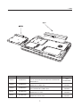
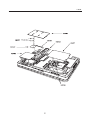
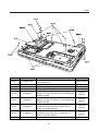
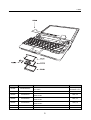
1
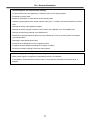
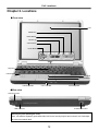
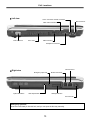
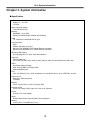
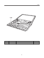
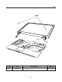
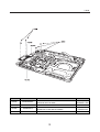
Service Manual (LW20) LG Electronics 0 Contents Ch 1. Service information Ch 2. Locations Ch 3. System information · Specification · Model configuration · System Block Diagram · Fn key combinations · Status indicators · BIOS Flash · BIOS Setup Ch 4. Symptom-to-part index · Power system checkout · Numeric error codes · Error messages · LCD-related symptoms · Indeterminate problems Ch 5. Removing and replacing a part (FRU) Ch 6. Part list · Part list · Exploded view 1 Ch1. Service information Chapter 1. Service information 1-1. Important service information Strategy for replacing parts (FRU-Field Replaceable Units) Before replacing parts Make sure that latest BIOS and drivers are installed before replacing any parts (FRUs) listed in this Use the following strategy to prevent unnecessary expense for replacing and servicing parts 1. If you are instructed to replacing a part but the replacement does not correct the problem, reinstall the original part before you continue. 2. Some computers have both a processor board and system board. If you are instructed to replace either the processor board or the system board, and replacing one of them does not correct the problem, reinstall that board, and then replace the other one. 3. If an adapter or device consists of more than one part, any of the parts (FRUs) may be the cause of the error. Before replacing the adapter or device, remove the parts (FRUs), one by one, to see if the symptoms change. Replace only the part that changed the symptoms. Caution The BIOS configuration on the computer you are servicing may have been customized. Running Automatic Configuration my alter the settings. Note the current configuration settings; then, when service has been completed, verify that those settings remain in effect. Strategy for replacing a hard-disk drive You have to get a User’s approval before formatting or replacing a hard-disk drive. You must let the User know that the user is responsible for the loss data Caution The drive startup sequence in the computer you are servicing may have been changed. Be extremely careful during write operations such as copying, saving, or formatting. If you select an incorrect drive, data or programs can be overwritten. 2 Ch1. Service information 1-2. Safety notices Warning Before the computer is powered-on after part (FRU) replacement, make sure all screws, springs, and other small parts are in place and are not left loose inside the computer. Verify this by shaking the computer and listening for rattling sounds. Metallic parts or metal flakes can cause electrical shorts. Warning some standby batteries contain a small amount of nickel and cadmium. Do not disassemble a standby battery, recharge it, throw it into fire or water, or short-circuit it. Dispose of the battery as required by local ordinances or regulations. Use only the battery in the appropriate parts listing. Use of an incorrect battery can result in ignition or explosion of the battery Warning The battery pack contains small amounts of nickel. Do not disassemble it, throw it into fire or water, or short-circuit it. Dispose of the battery pack as required by local ordinances or regulations. Use only the battery in the appropriate parts listing when replacing the battery pack. Use of an incorrect battery can result in ignition or explosion of the battery. Warning If the LCD breaks and the fluid from inside the LCD gets into your eyes or on your hands, immediately was the affected areas with water for at least 15 minutes. Seek medical care if any symptoms from the fluid are present after washing. Warning To avoid shock, do not remove the plastic cover that protects the lower part of the inverter card. Warning Though the main batteries have low voltage, a shorted or grounded battery can produce enough current to burn personnel or combustible materials. Warning Before removing any part (FRU), turn off the computer, unplug all power cords from electrical outlets, remove the battery pack, and then disconnect any interconnecting cables. 3 Ch1. Service information 1-3. Safety information General safety Follow these rules to ensure general safety · Observe good housekeeping in the area of the machines during and after maintenance. · When lifting any heavy object 1. Ensure you can stand safely without slipping. 2. Distribute the weight of the object equally between your feet. 3. Use a slow lifting force. Never move suddenly or twist when you attempt to lift. 4. Lift by standing or by pushing up with your leg muscles (This action removes the strain from the muscles in your back.) · Do not attempt to lift any object weights more then 16kg(35lb) or object that you think are too heavy for you. · Do not perform any action that causes hazards to the customer, or that makes the equipment unsafe. · Before you start the machine, ensure that other service representatives and the customer’s personnel are not in a hazardous position. · Place removed covers and other parts in a safe place, away from all personnel, while you are servicing the machine. · Keep your tool box away from walk areas so that other people will not trip over it. · Do not wear loose clothing that can be trapped in the moving parts of a machine. Make sure that your sleeves are fastened or rolled up above your elbows. If your hair is long, fasten it. · Insert the ends of your necktie or scarf inside clothing or fasten it with a nonconductive clip, approximately 8 centimeters(3 inches) from the end. · Do not wear jewelry, chains, metal-frame eyeglasses, or metal fasteners for you clothing. · Wear safety glasses when you are hammering, drilling, soldering, cutting wire, attaching springs, using solvents, or working in any other conditions that might be hazardous to your eyes. · After service, reinstall all safety shields, guards, labels, and ground wires. Replace any safety device that is worn or defective. · Reinstall all covers correctly before returning the machine to the customer. Caution Metal objects are good electrical conductors. 4 Ch1. Service information Electrical safety Observe the following rules when working on electrical equipment. Important Use only approved tools and test equipment. Some hand tools have handles covered with a soft material that does not insulate you when working with live electrical currents. Many customers have, near their equipment, rubber floor mats that contain small conductive fibers to decrease electrostatic discharges. Do not use this type of mat to protect yourself from electrical shock. · Find the room emergency power-off switch, disconnecting switch, or electrical outlet. If an electrical outlet. If an electrical accident occurs, you can then operate the switch or unplug the power cord quickly. · Do not work alone under hazardous conditions or near equipment that has hazardous voltages. · Disconnect all power before 1. Performing a mechanical inspection 2. Working near power supplies 3. Removing or installing main units · Before you start to work on the machine, unplug the power cord. If you cannot unplug it, ask the customer to power-off the wall box that supplies power to the machine and to lock the wall box in the off position. · If you need to work on a machine that has exposed electrical circuits, observe the following precautions : Ensure that another person, familiar with the power-off controls, is near you. Caution Another person must be there to switch off the power, if necessary. · Use only one hand when working with powered-on electrical equipment. Keep the other hand in your pocket or behind your back Caution An electrical shock can occur only when there is a complete circuit. By observing the above rule, you may prevent a current from through your body. · When using testers, set the controls correctly and use the approved probe leads and accessories for that tester 5 Ch1. Service information · Stand on suitable rubber mats (obtained locally, if necessary) to insulate you from grounds such as metal floor strips and machine frames. · Observe the special safety precautions when you work with very high voltages. These instructions are in the safety sections of maintenance information. Use extreme care when measuring high voltages. · Regularly inspect and maintain your electrical hand tools for safe operational condition. · Do not use worn or broken tools and testers. · Never assume that power has been disconnected from a circuit. First check that it has been powered off. · Always look carefully for possible hazards in your work area. Examples of these hazards are moist floors, non-grounded power extension cables, power surges, and missing safety grounds. · Do not touch live electrical circuits with the reflective surface of a plastic dental mirror. The surface is conductive such touching can cause personal injury and machine damage. · Do not service the following parts with the power on when they are removed from their normal operating places in a machine. 1. Power supply units 2. Pumps 3. Blowers and fans 4. Motorgenerators and similar units. (This practice ensure correct grounding of the units.) · If an electrical accident occurs 1. Use caution ; do not become a victim of yourself. 2. Switch off power. 3. Send another person to get medical aid. 6 Ch1. Service information Safety inspection guide The purpose of this inspection guide is to assist you in identifying potentially unsafe conditions. As each machine was designed and built, required safety items were installed to protect users and service personnel from injury. This guide addresses only those items. You should use good judgment to identify potential safety hazards due to attachment of non-LG features or options not covered by this inspection guide. If any unsafe conditions are present, you must determine how serious the apparent hazard could be and whether you can continue without first correcting the problem. · Consider these conditions and the safety hazards they present 1. Electrical hazards, especially primary power (primary voltage on the frame can cause serious or fatal electrical shock) 2. Mechanical hazards, such as loose or missing hardware Refer to the following checklist and begin the checks with the power off, and the power cord disconnected. · Checklist 1. Check exterior covers for damage (loose, broken, or sharp edges) 2. Power off the computer. Disconnect the power cord. 3. Check the power cord for : a. A third-wire ground connector in good condition. Use a meter to measure third-wire ground continuity for 0.1 or less between the external ground pin and frame ground. b. The power cord should be the type specified in the parts list. c. Insulation must not be frayed or worn. 4. Remove the cover. 5. Check for any obvious non-LG alterations. Use good judgment as to the safety of any non-LG alterations. 6. Check inside the unit for any obvious unsafe conditions, such as metal filings, contamination, water or other liquids, or signs of fire or smoke damage. 7. Check for worn, frayed, or pinched cables. 8. Check that the power-supply cover fasteners (screw or rivets) have not been removed or tampered with. 7 Ch1. Service information Handling devices that are sensitive to electrostatic discharge Any computer part containing transistors or integrated circuits (ICs) should be considered sensitive to electrostatic discharge (ESD). ESD damage can occur when there is a difference in charge between objects. Protect against ESD damage by equalizing the charge so that the machine, the part, the work mat, and the person handling the part are all at the same charge. Note Use product-specific ESD procedures when they exceed the requirements noted here. Make sure that the ESD protective devices you use have been certified (ISO9000) as fully effective. · When handling ESD-sensitive parts : 1. Keep the parts in protective packages until they are inserted into the product. 2. Wear a grounded wrist strap against your skin to eliminate static on your body. 3. Prevent the part from touching your clothing. Most clothing retains a charge even when you are wearing a wrist strap. 4. Use the black side of a grounded work mat to provide a static-free work surface. The mat is especially useful when handling ESD-sensitive devices. 5. Select a grounding system, such as those listed below, to provide protection that meets the specific service requirement. Note The use of a grounding system is desirable but not required to protect against ESD damage. a. Attach the ESD ground clip too any frame ground, ground braid, or green-wire ground. b. Use an ESD ground or reference point when working on a double-insulated or battery-operated system. You can use coax or connector-outside shells on these systems. c. Use the round ground-prong of the AC plug on AC-operated computers. Grounding requirements Electrical grounding of the computers is required for operator safety and correct system function. Proper grounding of the electrical outlet can be verified by a certified electrician. 8 Ch1. Service information 1-4. Laser compliance statement When a CD-ROM drive, DVD drive or the other laser product is installed, note the following : Caution Use of controls or adjustments or performance of procedures other than those specified here in might result in hazardous radiation exposure. Opening the CD-ROM drive, DVD-ROM drive or the other optical storage device could result in exposure to hazardous laser radiation. There are no serviceable parts inside those drives. Do not open Danger Emits visible and invisible laser radiation when open. Do not stare into the beam , do not view directly with optical instruments, and avoid direct exposure to the bean. 1-5. Backup (Standby) RTC battery safety information When replacing or disposing of the backup (standby) RTC battery, note the following : 9 Ch1. Service information 1-6. Read this first Before you go to the checkout guide, be sure to read this section. Important Notes · Only trained personnel certified by LG should service the computer. · Read the entire FRU removal and replacement page before replacing any FRU. · Use new nylon-coated screws when you replace FRUs. · Be extremely careful during such write operations as copying, saving, formatting. Drives in the computer that you are servicing sequence might have been altered. If you selected an incorrect drive, data or programs might be overwritten. · Replace FRUs only for the correct mode. · When you replace a FRU, make sure the model of the machine and the FRU part number are correct by referring to the FRU parts list. · A FRU should not be replaced because of a single, irreproducible failure. Single failures can occur for a variety of reasons that have nothing to do with a hard ware defect, such as cosmic radiation, electrostatic discharge, or software errors. · Consider replacing a FRU only when a problem recurs. If you suspect that a FRU is defective, clear the error log and run the test again. If the error does not recur, do not replace the FRU. · Be careful not to replace a non-defective FRU. What to do first You must fill out the record form first. During the warranty period, the customer may be responsible for repair costs if the computer damage was caused by misuse, accident, modification, unsuitable physical or operating environment, or improper maintenance by the customer. The following list provides some common items that are not covered under warranty and some symptoms that might indicate that the system was subjected to stress beyond normal use. Before checking problems with computer, determine whether the damage is covered under the warranty by referring to the following : 10 Ch1. Service information The followings are not covered under warranty : · CD panel cracked from the application of excessive force or from being dropped · Scratched (cosmetic) parts · Distortion, deformation, or discoloration of the cosmetic parts · Cracked or broken plastic parts, broken latches, broken pins, or broken connectors caused by excessive force · Damage caused by liquid spilled into system · Damage caused by improper insertion of a PC Card or the installation of an incompatible card · Damage caused foreign material in the diskette drive · Diskette drive damage caused by pressure on the diskette drive cover or by the insertion of a diskette with multiple labels · Damaged or bent diskette eject button · Fusses blown by attachment of a non-supported device · Forgotten computer password (making the computer unusable) · Sticky keys caused by spilling a liquid onto the keyboard The following symptoms might indicate damage caused by non-warranted activities : · Missing parts might be a symptom of unauthorized service or modification. · If the spindle of a hard-disk drive becomes noisy, it may have been subjected to excessive force, or dropped. 11 Ch2. Locations Chapter 2. Locations Front view LCD SRS Button MUTE Button Volume Up Volume Down Power Button Keyboard Internal MIC Touchpad Touchpad Button Internal Speaker 5-in-1 Card Slot Internal Speaker Rear view Security key hole S-VIDEO Connector USB Connector Security key hole (Kensington Lock) User can attach a separately purchased chain lock into the security keyhole and connect it to a fixed object to prevent a notebook theft 12 Ch2. Locations Left view Line-in Connector / SPDIF Connector MIC Connector IEEE 1394 Connector VGA Connector Fan Louver USB Connector Headphone Connector LAN Connector Right view Emergency eject hole Optical Disk Drive Modem Connector ODD Eject Button ODD Open Button AC Connector Emergency eject hole Insert a thin and hard pin into this hole, and you can open the disc tray manually. 13 Ch3. System information Chapter 3. System information Specification - CPU · Dothan 1.6 ~ 2.1 GHz · μFCPGA - Main Chipset & Graphic · Intel 915GM,ICH6-M - Memory · 2SODIMM – Up to 2GB · DDR2 PC2-3200S/4200S Capable (400/533MHz) - HDD · 1.8" 5mm/8mm 30/40/60GB PATA Type - Communication · MDC · Modem, Daughter Card Type · Marvell Yukon 88E8053 PCI-E Gigabit Ethernet Controller · Marvell Yukon 88E8036 PCI-E 10/100 Ethernet Controller - Wireless LAN Solution · 802.11bg/abg Mini PCI Type, Hexa-band Antenna - Card Slot · Express Card Slot · 5-in-I Card Slot (XD Picture, Memory Stick, Memory Stick Pro, Multi Media Card, SD Card) - ODD · Removable Optical Storage · DVD, DVD-COMBO, DVD Super Multi · Optional DMB Support - Port · VGA, 3X USB(2.0), RJ11, RJ45, Headphone, Line-in/SPDIF, Mic-in, AC-in, IEEE1394, S-Video - Input Devices · Keyboard : 86Key Keyboard · Touchpad - Buttons · Power, Volume Down, Volume Up, Mute, SRS - Indicator (LED) · Power On, Charge, HDD, Caps Lock, Num Lock, Wireless - Power · 65 Watt 18.5V 3.5A Adapter - Audio · Realtek Azalia Audio Codec ALC880, Stereo speakers - Battery · 6 Cell 4.8AHr, CYLINDRICAL (Li-Ion) 14 page48 15 page31 RJ45/RJ11 page44 Power rail & Battery Conn. page42 Miscellaneous page44 BATTERY CHARGER 5V/3.3V SYSTEM DC/DC page46 DDR2 DC/DC page47 GMCH_CORE VCCP page V1.2S / V1.5A Magnetic page31 page30 EEPROM HP/SPDIF SUB BD 5V 1.5V 3.3V 1.0V 1.8V 3.3V 3.3V MIC SUB BD SUB BD AMP 88E8036 page30 5V SUB B/D NEWCARD GbE SUB BD ALC880 AUDIO CODEC PORT 3 PORT 1 page37 MDC MODEM 88E8052 10/100 page13-15 AC’97 / AZALIA 1.8V SODIMM-0 /1 DDR2 DDR2 page20 CK-SSCD page20 CK-410M DIGITAL(3.3V) page45 ANALOGVCC(5V) 3.3V SUB B/D VCCP LPC 3.3V, 33MHz page21-26 ICH6-M DMI page 6-12 GMCH_CORE (1.05V) ALVISO-GM SUB BOARD SST49LF008A FWH PCI EXPRESS SUB BOARD DDR2 400/533 MHz page 2 - 4 FSB 533MHz VCCP CPU_CORE DOTHAN(NV) THERMAL SENSOR 3.3V page 5 page39 SUB BD TOUCH PAD 3.3v H8S2110B page18 page19 CRT CONN page09 3V page27 SATA TO PATA 3.3V S-VIDEO CONN 5V 3.3V LCD CONN page 5 FAN CONN 5V 5V SUB BOARD SUB BD VOLUME S/W page40 USB7 USB6 USB5 USB3 USB2 page28 SUB BOARD CHG ACIN PWR ON NUM LOCK CAPS LOCK HDD Wireless LEDs 3.3V 3.3V SUB B/D USB5 SUB B/D USB0 4 IN 1 1394 PORT 3.3V 5V NEWCARD page38 SUB BOARD USB7 page28 page34-36 page33 USB6 page28 SUB B/D USB5 page27 USB3 page29 USB2 AD16 PCI7411 AD18 MINI PCI CONN HDD USB0/1 3V USB0/1 PIRQA,SERIRQ PCIREQ/GNT0 PIRQC/D PCIREQ/GNT3 POWER S/W page45 INT. KBD USB Interface page28 BAY CONN. PCI 3.3V,33MHz PATA 66/100 SATA WIND RIVER TV/CRT/LVDS CPU CORE VCC Ch3. System information System Block Diagram Ch3. System information Fn key combinations The following table shows the function of each combination of Fn with a function key. Function of Fn keys has nothing to do with Operating System. [Fn] + [F1] User defined Hot key. (available from OSD Setting) [Fn] + [F2] User defined Hot key. (available from OSD Setting) [Fn] + [F3] User defined Hot key. (available from OSD Setting) [Fn] + [F4] Forces the computer to enter power-saving mode. (ex: system standby and hibernation) [Fn] + [F5] Press the combination once to disable the touch pad, and press again to enable the touch pad. (The touch pad initialization takes 1~2 seconds, so wait for the initialization to end before using the touch pad) [Fn] + [F6] Wireless LAN Enable/Disable Toggle. [Fn] + [F7] Monitor toggle. When the computer is attached to an external monitor, you can change the display output location with [Fn] + [F7] combination. You can switch to and from the three types of display modes, LCD display only, the external monitor only, or both at the same time. Audio Enable/disable [Fn] + [F8] •Refer to Battery Miser 2005 Help. LCD Auto Brightness control Enable/Disable. Enable/disable Auto Brightness control. (ON/OFF) [Fn] + [F9] •Refer to Battery Miser 2005 Help. [Fn] + [F10] System information. [Fn] + [F11] CPU Cooling Fan control mode (Normal / Slow / Fast). [Fn] + [F12] Maximum power-saving mode. (When OSD is installed.) [Fn] + Home Darken the LCD (8 Steps). [Fn] + End Brighten the LCD (8 Steps). [Fn] + Scr Lk [Num Lk] Num Lock [Fn] + [Delete] Insert Fn + PgUp (Prt Sc Sys Rq) Print Screen Fn + PgDn (Pause Break) Pause 16 Ch3. System information Status indicators The system status indicators show the status of the computer 1. 2. 3. 4. 5. 6. 1. Num lock Num lock indicator lights up when Num lock key is pressed. By pressing Fn + Scr LK (Num LK) key, you can use the embedded numeric keys. To disable the embedded numeric keys, press Fn + Scr LK (Num LK) key again. - The Num Lock indicator is off while an external keyboard is connected if OSD keyboard setup is configured not to use embedded keypad with an external keyboard connection. 2. Caps lock Caps lock indicator lights up when the Caps lock key is pressed. When this indicator lights up, you can type capital letters without pressing the Shift key. 3. Drive in use Drive in use indicator lights up when data is being written to or read from the hard disk or optical disk drive. - Do not turn off the power when Drive in use indicator is on. It may result in loss of data in the hard disk. 4. Wireless activity indicator Off: Wireless LAN is not in use. Blinking(3-4 Seconds): Searching for Access point for Wireless LAN Connection. Blinking (short interval): Data is transferring with Wireless LAN is on. 5. Power Power status indicator indicates the following status of the computer. Off: The computer is turned off or is in hibernation mode. On: The computer is turned on. Blinking: The computer is in standby mode. 6. Battery status indicator Orange light: Battery is being charged. Orange light/ Blinking (Green): Battery is being charged - battery is remaining more than 90% of its maximum capacity. Off: Battery is being discharged. Green: Battery is fully charged or empty while the AC adapter is connected. Blinking (Green): Battery is remaining less than 10%, or being discharged. Blinking (Red): A battery error occurs. - The Battery indicator blinks as you have set the alarm action from the Battery miser 2005. 17 Ch3. System information BIOS Flash You can update BIOS using a floppy disk drive. Because this system is not equipped with any floppy disk drive, you have to use an external USB drive for a BIOS update. In order to boot up with an USB drive, please set Removable Device as the first boot up drive in the boot menu of BIOS setup. · How to update flash ROM in DOS 1. Create ‘boot up’ flash update diskette. 2. Copy a ROM image file (*.wph) into the root of the flash update diskette. 3. Copy phlash16.exe to the flash update diskette. 4. Insert the diskette into the FDD of your computer. 5. Boot your computer with the diskette, and type ‘phlash16*.wph /mode=n’. 6. Cold boot and follow the instruction displayed on the screen. · Flash options /mode=n 0 – Default mode. Keep the current DMI information and update BIOS image only. 1 – Update DMI information only. If new DMI information is not specified, the current DMI information is left unchanged. 2 – Update BIOS and DMI information. If new DMI information is not specified, the current DMI information is left unchanged. 3 – Update BIOS and DMI information. DMI information is updated to the DMI string and options specified in the new BIOS image. Note DMI is Desktop Management Interface 18 Ch3. System information BIOS Setup BIOS (Basic Input and Output System) Setup saves the system configuration in CMOS RAM, and check the configurations during startup. Use the BIOS Setup Utility to change and save the system environment, hardware configurations, power saving mode, etc. · Open the BIOS Setup Utility in the following situations : 1. to change the BIOS setup 2. to replace the backup battery 3. system configuration error occurs 4. to change the boot order 5. to set/change a password Press the power button. When the LG logo appears on the screen, press and enter the BIOS Setup Utility. 19 Ch3. System information Using the keys The keys used in the BIOS Setup Utility and their functions are described at the bottom. · , + : General Help Display the descriptions of the keys used in the setup utility. · , : Select Item Navigate and select items in the setup utility. The selected item becomes highlighted. · , : Select Menu Move to another menu. · / , : Change Values Change the value of a selected item. · : Load Default Configuration Display Setup Confirmation window. Press Enter to load default configuration. · : Select Sub-Menu Some items have sub-menus. Display the sub-menu for a selected item. · : Save and Exit Display Setup Confirmation window. Press Enter to save and exit. · : Exit In a sub-menu, press Esc to move to the previous window. In Main menu, click Esc to move to Exit menu. 20 Ch3. System information Main menu System Time Current time. Use <Tab>, <Shift-Tab>, or <Enter> keys to move around these fields. To change the value, press <+> or <−> key. System Date Today date. Use <Tab>, <Shift-Tab>, or <Enter> keys to move around these fields. To change the value, press <+> or <−> key. Set any date from year 1981 to 2079. It will automatically keep track of leap years. The system date can also be set from the operating system. Product Name This shows the name of PC. Processor Type This shows the type of CPU. Processor Spd This shows the speed CPU. BIOS Version This shows the Version of BIOS. KBC Version This shows the Version of KBD firm ware. UUID This is for display only. This shows the UUID. Pri Master Enter its submenu by pressing <Enter>. In this submenu, it would show the device of Primary IDE Master is HDD and its parameters. Sec Slave Enter its submenu by pressing <Enter>. In this submenu, it would show the device of Secondary IDE Slave is optical drive and its parameters. Total Memory This is for display only. This shows size of system memory. 21 Ch3. System information Advanced menu Legacy USB Support There are two options to this field: Enabled, and Disabled. This field allows you to enable or disable the legacy USB support. Boot-time Diagnostic Screen Enables the Boot-time Diagnostic Screen. SATA Controller Mode Set SATA (Serial ATA) Controller Mode. AHCI Configuration Enables the AHCI (Advanced Host Controller Interface). Battery Charge Stop Percentage Set Battery Charge Stop Percentage. Fan Mode Control Set Fan Mode Control. Fn Key Setup Set Sticky fn key function. Wake On Lan Enables Wake On Lan. PXE/Remote Boot Enables PXE/Remote Boot. Execute-Disable Bit Capability Enables Execute-Disable Bit Capability. Security menu Supervisor Password Is This shows the system’s supervisor password has been set, or not. Set Supervisor Password Set Supervisor Password. User Password Is This shows the system’s User Password has been set, or not. Set User Password Set User Password. Password on boot Enables Password on boot. HDD Password Is This shows the system’s HDD Password has been set, or not. Set HDD Password Set HDD Password. 22 Ch3. System information Boot menu Boot menu enables you to set the boot order for the CD-ROM drive, Removable devices Hard drive, and Network boot as shown below. CD-ROM Drive Removable Devices Hard Drive B2 D0 Yukon PXE Exit menu Exit Saving Changes Select Exit Saving Changes to save new setup information in CMOS RAM. CMOS RAM stores the information using the backup battery; therefore, the information will not be lost when the computer is turned off. Exit Discarding Changes Select Exit Discarding Changes to discard new setup information. If you made changes to items other than date, time, and passwords, the Setup Warning asks you to save the new configurations. Select Yes and press Enter to save the new configuration. Load Setup Defaults Select Load Setup Defaults to change the setup information to the factory default settings. If you select Load Setup Defaults or press F9, Setup Confirmation asks you to confirm your selection. Press Yes to load setup defaults. Discard Changes Discard change value. Save Changes Save change value. 23 Ch4. Symptom-to-part index Chapter 4. Symptom-to-part index The symptom-to-part index in this section lists symptoms and errors and their possible causes. The most likely cause is listed first. Note If replacing a part (FRU) does not solve the problem, put the original part back in the computer. Do not replace a non-defective FRU. Power system checkout · To verify a symptom, do the following : 1. Power off the computer. 2. Remove the battery pack. 3. Connect the AC adapter. 4. Check that power is supplied when you power on the computer. 5. Power off the computer. 6. Disconnect the AC adapter and install the charged battery pack. 7. Check that the battery pack supplies power when you power on the computer. · If you suspect a power problem, see the appropriate one of the following power supply checkouts : 1. Checking the AC adapter 2. Checking the operational charging 3. Checking the battery pack 4. Checking the backup battery 24 Ch4. Symptom-to-part index · Checking the AC adapter If the power-on indicator does not turn on, check the power cord of the AC adapter for correct continuity and installation. If the computer does not charge during operation, go to “Checking operational charging.” To check the AC adapter, do the following : 1. Unplug the AC adapter cable from the computer. 2. Measure the output voltage at the plug of the AC adapter cable. See the following figure: 3. If the measured output voltage is incorrect, remove the power cord from the AC adapter and then reconnect it in about ten seconds. 2 1 4. Measure the output voltage at the plug of the AC adapter cable. 5. If the measured output voltage is incorrect, replace the AC adapter. 25 Pin Voltage (V dc) 1 +18.0 ~ +19.2 2 Ground Ch4. Symptom-to-part index · If the voltage is not correct, replace the AC adapter. · If the voltage is acceptable, do the following : 1. Replace the system board. 2. If the problem persists, check the AC adapter whether it is correct product or not. Note Noise from the AC adapter does not always indicate a defect. · Checking operational charging 1. To check whether the battery charges properly during operation, use a discharged battery pack or a battery pack that has less than 50% of the total power remaining when installed in the computer. Perform operational charging. If the battery status indicator or icon does not turn on, remove the battery does not turn on, replace the battery pack. 2. If the charge indicator still does not turn on, replace the system board. Then reinstall the battery pack. Note Do not charge battery pack, when its temperature is below 0 or above 75 . · Checking the battery pack 1. Open the Power Meter window by clicking Start Control Panel Power Options and then; check the total power remains. Battery charging does not start until the power Meter shows that less than 95% of the total power remains; under this condition the battery pack can charge to 100% of its capacity. This protects the battery pack from being overcharged or from having a shortened life. 2. To check the status of your batter, move your cursor to the Power Meter icon in the icon tray of the Windows taskbar and wait for a moment (but do not click), and the percentage of battery power remaining is displayed. To get detailed information about the battery, double-click the Power Meter icon. Note If the battery pack becomes hot, it may not be able to charge. Remove it from the computer and Leave it at room temperature for a while. After it cools down, reinstall and recharge it. 26 Ch4. Symptom-to-part index · The Characteristics of the battery pack 1. Self-discharge The battery gradually loses its power over time without ever being used. 2. Periodic full discharge / charge Frequent recharge of the battery pack can reduce the capacity of the battery pack. When this happens, you can perform the full discharge / charge to improve the capacity. You should perform periodic full discharge /charge once every 30~60 days. You should always use the battery until its power is low; then fully charge the battery. 3. Trickle charge If the temperature of the battery pack drops below 10 , the trickle charging begins. The trickle charging may take 32 hours for the battery pack to be fully charged. 27 Ch4. Symptom-to-part index · To check the battery pack, do the following : 1. Power off the computer. 2. Remove the battery pack and measure the voltage between battery terminals 1(-) and 5(+). See the following figure : 5(+) 4 3 Terminal Voltage (V dc) 1 Ground(-) 5 +0V ~ +12.6V (6 cell) 2 1(-) 3. If the voltage is still less than +11.1 V DC after recharging, replace the battery. 4. If the voltage is more than +11.1 V DC, measure the resistance between battery terminals 1 and 2. The resistance must be 2 to 4 (typically 3 ). 5. If the resistance is not correct, replace the battery pack. If the resistance is correct, replace the system board. Note Charging will take at least 3 hours. Note Battery is an expendable supplier, so its capacity and used time can be reduced by using the computer. 28 Ch4. Symptom-to-part index Numeric error codes Symptom / Error FRU or action, in sequence 0200 Fixed disk failure (The hard disk is not working) 1.Reset the hard-disk drive. 2.Load Setup Defaults in BIOS Setup Utility. 3.Hard-disk drive. 4.System board. 0210 Stuck Key error 1.Check the keyboard if it is pressed. 2.Replace the keyboard. 0211 Keyboard error Run interactive tests of the keyboard and the auxiliary input device. 0212 Keyboard Controller Failed System board. 0220 Monitor type error - Monitor type does not match the one specified in CMOS. Load Setup Defaults in BIOS Setup Utility. 0230 System RAM error - System RAM Failed at offset. 1.DIMM 2.System board 0231 Shadow RAM error - Shadow RAM failed at offset System board 0232 Extended RAM error - Extended RAM Failed at address line 1. DIMM 2. System board 0250 System battery error – System battery is dead Replace the backup battery and run BIOS Setup Utility to reset the time and date. 29 Ch4. Symptom-to-part index Symptom / Error FRU or action, in sequence 0251 System CMOS checksum bad – System CMOS checksum is not correct. – Default configuration used. Replace the backup battery and run BIOS Setup Utility to reset the time and date. 0252 Password checksum bad – The password is cleared. Reset the password by running BIOS Setup Utility. 0260 System timer error 1. Replace the backup battery and run BIOS Setup Utility to reset the time and date. 2. System board. 0271 Check date and time settings – Date and time error. Run BIOS Setup Utility to reset the time and date. 0280 Previous boot incomplete - Default configuration used 1. Load “Setup Default” in BIOS Setup Utility. 2. DIMM. 3. System board. 0281: Memory Size found by POST differed from EISA CMOS Load Setup Defaults in BIOS Setup Utility. 02D0 System cache error – Cache disabled (RAM cache failed and BIOS disabled) 1. Load “Setup Default” in BIOS Setup Utility. 2. System board. 02F4 EISA CMOS not writable 1. Load “Setup Default” in BIOS Setup Utility. 2. Replace the backup battery. 3. System board. 02F5 DMA test failed 1. DIMM 2. System board 02F6 Software NMI failed 1. DIMM 2. System board 30 Ch4. Symptom-to-part index Symptom / Error FRU or action, in sequence 02F7 Fail – Safe timer NMI failed 1. DIMM 2. System board 0611 IDE configuration changed 1. Load Setup Defaults in BIOS Setup Utility. 2. System board. 0612 IDE configuration error 1. Load Setup Defaults in BIOS Setup Utility. 2. System board. 0613 Com A configuration changed 1. Load Setup Defaults in BIOS Setup Utility. 2. System board. 0614 Com A configuration error 1. Load Setup Defaults in BIOS Setup Utility. 2. System board. 0615 Com B configuration changed 1. Load Setup Defaults in BIOS Setup Utility. 2. System board. 0616 Com B configuration error 1. Load Setup Defaults in BIOS Setup Utility. 2. System board. 0617 Floppy configuration changed 1. Load Setup Defaults in BIOS Setup Utility. 2. System board. 0618 Floppy configuration error 1. Load Setup Defaults in BIOS Setup Utility. 2. System board. 0619 Parallel port configuration changed 1. Load Setup Defaults in BIOS Setup Utility. 2. System board. 061A Parallel port configuration error 1. Load Setup Defaults in BIOS Setup Utility. 2. System board. 31 Ch4. Symptom-to-part index Error message Symptom / Error FRU or action, in sequence Device address conflict. 1. Load Setup Defaults in BIOS Setup Utility. 2. Backup battery. 3. System board. Allocation error for device. 1. Load Setup Defaults in BIOS Setup Utility. 2. Backup battery. 3. System board. Failing bits: nnnn. 1. DIMM. 2. System board. Invalid System Configuration Data. 1. DIMM. 2. System board. I/O Device IRQ Conflict. 1. Load Setup Defaults in BIOS Setup Utility. 2. Backup battery. 3. System board. Operating System not found. 1. Check that the operating system has no failure and is installed correctly. 2. Enter BIOS Setup Utility and see whether the hard -disk drive and the diskette drive are properly identified. 3. Reset the hard-disk drive. 4. Reinstall the operating system. 5. Diskette drive. 6. Hard-disk drive. 7. System board. Hibernation error. 1. Restore the system configuration to what it was before the computer entered hibernation mode. 2. If memory size has been changed, re-create the hibernation file. FAN error. Fan. Thermal sensing error. System board. 32 Ch4. Symptom-to-part index LCD-related symptoms Note Before removing or disassembling LCD, power off the computer, unplug all power cords from electrical outlets, remove the battery pack also. Symptom / Error FRU or action, in sequence LCD screen becomes dark suddenly. Check out Battery Miser. Nothing displayed on LCD screen. 1. Check out Battery Miser. 2. Choose Never in the Turn off Monitor item on Power Options Properties. 3. Check the power save mode switch if it is pressed by something. 4. Check the System is in standby or hibernation mode. LCD backlight not working. LCD too dark. LCD brightness cannot be adjusted. 1. Reconnect inverter to the board connector. 2. Replace inverter. 3. LCD assembly. 4. System board. LCD color cannot be adjusted. LCD screen abnormal. Characters missing pixels. LCD screen unreadable. Wrong color displayed. 1. Reset all LCD connectors. 2. Replace LCD cable. 3. LCD assembly. 4. System board. Horizontal or vertical lines displayed on LCD LCD assembly. Power-on indicator on, and a blank\LCD during POST. LCD assembly. System board. 33 Ch4. Symptom-to-part index Indeterminate problems · You are here because the diagnostic tests did not identify which adapter or device failed, wrong devices are installed, a short circuit is suspected, or the system is inoperative. Follow these procedures to isolate the failing FRU (do not isolate FRUs that have no defects). · Verify that all attached devices are supported by the computer. · Verify that the power supply being used at the time of the failure is operating correctly. 1. Power off the computer 2. Visually check each FRU for damage. Replace any damaged FRU. 3. Remove or disconnected all of the following devices : a. Non-LG devices. b. Printer, mouse, and other external devices. c. Battery pack. d. PC cards. e. ODD (CD-ROM, Combo) drive or FDD drive in the Bay. f. Hard-disk drive. Note Use the other memory card because it needs when operating computer. 4. Power on the computer. 5. Determine whether the problem has changed. 6. If the problem does not recur, reconnect the removed devices one at a time until you find the failing FRU. 7. If the problem remains, replace the following FRUs one at a time. (do not replace a non-defective FRU) a. LCD assembly (Check external monitor whether the same problem recurs or not). b. Keyboard. c. Keydeck (TouchPad and Scroll Button assembly). d. System board. 34 Ch5. Removing and replacing a part Chapter 5. Removing and replacing a part (FRU) Danger Before removing any FRU, power off the computer, unplug all power cords from electrical outlets, remove the battery pack, and then disconnect any interconnecting cables. Caution Before the computer is powered on after FRU replacement, make sure that all screws, springs, and other small parts are in place and are not loose inside the computer. Verify metal flakes can cause electrical short circuits. Note As for the screw, every Torque 3 0.2Kgfcm(0.196Nm) 35 Ch5. Removing and replacing a part ■ 1010 Battery Pack 1. Push the battery latch in the direction shown below; then slide the battery pack out of the slot. 36 Ch5. Removing and replacing a part ■ 1020 Hard Disk Drive Remove the following parts in order before replacing this part. 1. Battery Pack(1010) 1. Remove 2 HDD Cover Screws. 2. Open HDD Cover, then remove HDD. 37 Ch5. Removing and replacing a part ■ 1030 Optical Disk Drive Remove the following parts in order before replacing this part. 1. Battery Pack(1010) 1. Push the ODD Knob in the direction shown below, then remove ODD from slot. 38 Ch5. Removing and replacing a part ■ 1040 Retainer Remove the following parts in order before replacing this part. 1. Battery Pack(1010) 2. Hard Disk Drive(1020) 1. Remove 2 Screws. No. FRU No. Specification Qty 1 1SZZBA4080A D4.0 X L4.0 2 2. Pull up the Hinge Cap using a (-) type screwdriver. 39 Ch5. Removing and replacing a part 3. Disconnect Retainer Connector. 4. Remove Retainer. 40 Ch5. Removing and replacing a part ■ 1050 Keyboard Remove the following parts in order before replacing this part. 1. Battery Pack(1010) 2. Hard Disk Drive(1020) 3. Retainer(1040) 1. Remove 12 Screws. No. FRU No. Specification Qty 1 1SZZBA4097B D4.5 X L6.5 12 2. Disconnect Keyboard Connector. 41 Ch5. Removing and replacing a part 2. Remove Keyboard. 42 Ch5. Removing and replacing a part ■ 1060 Display Module Remove the following parts in order before replacing this part. 1. Battery Pack(1010) 2. Hard Disk Drive(1020) 3. Retainer(1040) 4. Keyboard(1050) 1. Remove 2 Hinge Screws. (Left / Right) No. FRU No. Specification Qty 1 1SZZBA4097B D4.5 X L6.5 2 2. Remove Display Module. 43 Ch5. Removing and replacing a part ■ 1070 Key Deck Remove the following parts in order before replacing this part. 1. Battery Pack(1010) 2. Hard Disk Drive(1020) 3. Retainer(1040) 4. Keyboard(1050) 5. Display Module(1060) 1. Disconnect RTC Battery Connector then, remove RTC Battery. 2. Remove 7 Screws. No. FRU No. Specification Qty 1 1SZZBA4080A D4.0 X L4.0 7 44 Ch5. Removing and replacing a part 2. Disconnect Touchpad Connector. 3. Remove Key Deck. 45 Ch5. Removing and replacing a part ■ 1080 Sub B/D Remove the following parts in order before replacing this part. 1. Battery Pack(1010) 2. Hard Disk Drive(1020) 3. Retainer(1040) 4. Keyboard(1050) 5. Display Module(1060) 6. Key Deck(1070) 1. Remove 5 Sub B/D Screws. No. FRU No. Specification Qty 1 1SZZBA4080A D4.0 X L4.0 5 2. Remove Sub B/D. 46 Ch5. Removing and replacing a part ■ 1090 Speaker Remove the following parts in order before replacing this part. 1. Battery Pack(1010) 2. Hard Disk Drive(1020) 3. Retainer(1040) 4. Keyboard(1050) 5. Display Module(1060) 6. Key Deck(1070) 7. Sub B/D(1080) 1. Remove 4 Speaker Screws. No. FRU No. Specification Qty 1 1SZZBA4027A D8.0 X L6.5 4 2. Remove Speakers. 47 Ch5. Removing and replacing a part ■ 1100 Fan Assembly Remove the following parts in order before replacing this part. 1. Battery Pack(1010) 2. Hard Disk Drive(1020) 3. Retainer(1040) 4. Keyboard(1050) 5. Display Module(1060) 6. Key Deck(1070) 7. Sub B/D(1080) 8. Speaker(1090) 1 1 1. Remove 5 Screws. 2 1 1 No. FRU No. Specification Qty 1 1SZZBA4020A D4.0 X L8.8 4 2 1SZZBZ4014C D2.0 X L5.0 1 2. Remove Fan Assy. 48 Ch5. Removing and replacing a part ■ 1110 Main Board Remove the following parts in order before replacing this part. 1. Battery Pack(1010) 2. Hard Disk Drive(1020) 3. Retainer(1040) 4. Keyboard(1050) 5. Display Module(1060) 6. Key Deck(1070) 7. Sub B/D(1080) 8. Speaker(1090) 9. Fan Assy(1100) 1. Remove ODD Plate. 2. Remove 3 Screws, then remove I/O Jack Sub Board. No. FRU No. Specification Qty 1 1SZZBA4080A D4.0 X L4.0 3 49 Ch5. Removing and replacing a part 3. Remove a Screw, then remove Hinge Left. No. FRU No. Specification Qty 1 1SZZBA4080A D4.0 x L4.0 1 4. Remove a Screw, then remove Hinge Right. No. FRU No. Specification Qty 1 1SZZBA4080A D4.0 x L4.0 1 50 Ch5. Removing and replacing a part 1 5. Remove 2 Screws and 1 Hexagon Screw. 1 2 No. FRU No. Specification Qty 1 1SZZBA4080A D4.0 X L4.0 2 2 1SZZBA4101A D2.0 x L11.5 1 6. Remove Main Board. 51 Ch5. Removing and replacing a part 52 Ch5. Removing and replacing a part ■ 1120 Display Module Exploded View Remove the following parts in order before replacing this part. 1. Battery Pack(1010) 2. Hard Disk Drive(1020) 3. Retainer(1040) 4. Keyboard(1050) 5. Display Module(1060) 1. Remove 6 Rubber Caps, then remove 4 Screws. No. FRU No. Specification Qty 1 1SZZBA4104A D2.5 X L4.5 4 2. Remove LCD Front. 53 Ch5. Removing and replacing a part 3. Remove 4 Screws. No. FRU No. Specification Qty 1 1SZZBA4104A D2.5 X L4.5 4 4. Remove LCD Hinge. (Left / Right). 54 Ch5. Removing and replacing a part 5. Remove Inverter. 55 Ch5. Removing and replacing a part 6. Disconnect LED Sub Board Connector. 56 Ch5. Removing and replacing a part 7. Remove 2 Screws, then remove LED Sub Board. No. FRU No. Specification Qty 1 1SZZBA4041A D3.5 X L3.0 2 8. Remove LED Lens. 57 Ch5. Removing and replacing a part 9. Remove 2 Screws, then remove Left Antenna. No. FRU No. Specification Qty 1 1SZZBA4041A D3.5 X L3.0 2 10. Remove 2 Screws, then remove Right Antenna. No. FRU No. Specification Qty 1 1SZZBA4041A D3.5 X L3.0 2 58 Ch5. Removing and replacing a part 59 Ch5. Removing and replacing a part 12. Remove 4 Screws, then remove LCD Brackets. No. FRU No. Specification Qty 1 1SZZBA4041A D3.5 X L3.0 4 13. Disconnect LCD Cable. 60 Ch6. Part lists Chapter 6. Part lists 2005-06-20 Location Part Number Specification NCPU1 0IMCR00003A RH80536GE0462M LG INTEL 478P UFCPGA TRAY NT CPU PENTIUM-M 770 2.13GHZ/800MHZ C0-STEPPING(SL7SL) NCPU1 0IMCR00005A RH80536GE0412M LG INTEL 478P UFCPGA TRAY NT CPU PENTIUM-M 760 2.00GHZ/800MHZ C0-STEPPING(SL7SM) NCPU1 0IMCR00007A RH80536GE0362M LG INTEL 478P UFCPGA TRAY NT CPU PENTIUM-M 750 1.86GHZ/800MHZ C0-STEPPING(SL7S9) NCPU1 0IMCR00009A RH80536GE0302M LG INTEL 478P UFCPGA TRAY NT CPU PENTIUM-M 740 1.73GHZ/800MHZ C0-STEPPING(SL7SA) NMEM1 0IMMR00005B M470T3354BZ0-CD5 SAMSUNG ELECTRONICS 200P SODIMM BK 256MB 32MX64 533MHZ DDR2 SDRAM WITH 32MX16 PB FR NMEM1 0IMMR00008A HYS64T64020HDL-3.7-A INFINEON 200P SODIMM BK 512MB 64MX64 533MHZ DDR2 SDRAM WITH 32MX16 NMEM1 0IMMR00053B HYMP532S64P6-C4 HYNIX 200P SODIMM BK 256MB 32MX64 533MHZ DDR2 SDRAM WITH 32MX16 LUS08 1SZZBA4080A + D4.0 L4.0MM SWRH4 M2 H1.0 SILVER K2 TIP#0 NSCRB 1SZZBA4104A + D2.5 L4.5MM MSWR3 / FN . BK WINDRIVER . NSCR7 1SZZBA4097B + D4.5 L6.5MM SWRH4 M2.5 H1.0 BK HUNTER TIP NO.0 ROHS 160 NSCR9 1SZZBA4101A HEXAGON D2.0 L11.5MM BSP, BSW HEXA SAMWON YL WINDRIVER M2 H6.0MM INNER HTM18 1SZZBZ4020A + D4.0 L8.8MM SWRH4 FAN ASSEMBLY SILVER MCKINLEY L(10.0) WITH HEAD LENGTH TIP#0 NSCRA 1SZZBZ4027A + D8.0 L6.5MM MSWR3 / FN SPEAKER SILVER WINDRIVER SPEAKER SCREW NODD2 2026B10007A UJ-822BPT1-G PCC 8X 8X 24X 24X 10X 2X 2X 2.4X 2.4X 2X 24X NOTE BOOK 9.5MM ROHS WINDRIVER SUPER MULTI NODD2 2029B09004A GCC-4246N HLDS 8X 24X 24X 24X 9.5MM ROHS WINDRIVER COMBO ASSY NODD2 2029B09005A UJDA765 PANASONIC 8X 24X 24X 24X 9.5MM ROHS WINDRIVER COMBO ASSY NCSE5 3110BD0020A WINDRIVER MG BOTTOM CASE NFRM2 3110BM3036A WINDRIVER ZN HINGE FRAME R NFRM1 3110BM3037A WINDRIVER ZN HINGE FRAME L NCSE4 3111B0TS79A WINDRIVER KBD DECK ASS Y NCSE3 3111B97122A WINDRIVER DISPLAY FRONT ASSY NPLT1 3300BP3520A PLATE WINDRIVER ODD BAY 61 WNR05 Remarks Ch6. Part lists Location Part Number Specification NPLT2 3300BP4472A PLATE WINDRIVER HDD NCVR2 3550BM4200A WINDRIVER PCABS . ODD WEIGHT SAVER COVER NCVR3 3551B90003A WINDRIVER . RETAINER ASSY (수출향) NCVR4 3551B90004B WINDRIVER MEMORY DOOR ASSY NCVR5 3551B90005A WINDRIVER . 4 IN 1 ASSY NCVR6 3551B90006B WINDRIVER . MINI PCI ASSY NCVR7 3551B90008A WINDRIVER HDD COVER NCSN2 3610BM4033A WINDRIVER RUBBER SPEAKER CUSHION NCSN1 3610BP4025A WINDRIVER RUBBER BOTTOM NLED1 3680BM4092A WINDRIVER PMMA LED DISPLAY 12.1INCH NKBD2 3823B01150A KOREA WINDRIVER SUNREX 84KEY NKBD2 3823B01151A US ENGLISH WINDRIVER SUNREX 84KEY NLBL2 3850BB9214A ID LABEL WINDRIVER . NSHT2 3858BP4480A N WINDRIVER BADGE LG LOGO NSHT3 3858BP4482A . WINDRIVER SPEAKER GRILL LEFT NSHT4 3858BP4483A . WINDRIVER SPEAKER GRILL RIGHT NSHT5 3858BZ3038A . WINDRIVER SHEET INSULATION BOTTOM NSHT6 3858BZ4498A . WINDRIVER SHEET INSULATION BOTTOM RIGHT NHNG2 4775B00057A WINDRIVER 6.5 KGF-CM HINGE RIGHT LATCHLESS 12.1INCH NHNG1 4775B00058A WINDRIVER 6.5 KGF-CM HINGE LEFT LATCHLESS 12.1INCH NBRK1 4810BP3353A WINDRIVER SUS LCD LEFT 0.5T 12.1INCH NBRK2 4810BP3354A WINDRIVER SUS LCD RIGHT 0.5T 12.1INCH NCSN3 4850BP4067A WINDRIVER RUBBER DISPLAY FRONT UPPER 12.1INCH NCSN4 4850BP4068A WINDRIVER RUBBER DISPLAY FRONT LOWER 12.1INCH NCSN5 4850BP4071A WINDRIVER EVA DISPLAY REAR CENTER NCSN6 4850BP4072A WINDRIVER EVA DISPLAY REAR LEFT NCSN7 4850BP4073A WINDRIVER EVA DISPLAY REAR RIGHT NCSN9 4850BP4078A WINDRIVER EVA DISPLAY REAR LCD CONN NHLD4 4930BM3101A WINDRIVER RUBBER HDD HOLDER NHLD1 4930BM4045A WINDRIVER PCABS BATTERY KNOB HOLDER LEFT NHLD2 4930BM4046A WINDRIVER PCABS BATTERY KNOB HOLDER RIGHT NHLD3 4930BM4047A WINDRIVER PCABS DRIVE KNOB LOCK HOLDER NNOB1 4940BM4174A WINDRIVER PCABS BATTERY KNOB 62 Remarks Ch6. Part lists Location Part Number Specification NNOB2 4940BM4175A WINDRIVER PCABS DRIVE KNOB LOCK NSPR1 4970BW4570A WD0.25MM ID3.0MM N9 L11.0MM 0.6KGF WINDRIVER BATEERY SPRING NANT2 5011B00026A HITACHI WIRELESS R WINDRIVER NANT1 5011B00027A HITACHI WIRELESS L WINDRIVER MKM16 5022BZ4025A THERMAL PCS-TC-11-T-13 19X19MM T130UM ZEBRA-2(MOBILE) GRAY K=4.7(W/M-C) NPADN 5022BZ4027A THERMAL SILICON 12X12MM, 0.5T HUNTER COH2003, DARK ORANGE, CONDUCTIVIEY 3.5W/MK, NORTHBRDIGE NFAN2 5901B09287A THERMAL FAN ASSY WINDRIVER TOSHIBA NLCD2 6304FCI010A N121I1-L02 CHIMEI TFT COLOR 12.1 INCH WXGA 1280X800 LVDS 200NITS GLARE NSPK2 6401B02546A . ESTEC 1.5W . . SPECKER R WINDRIVER NSPK1 6401B02547A . ESTEC 1.5W . . SPEAKER L WINDRIVER NCABC 6410BM21002 PT8XXK9KB0A-033 LONGWELL KS 1000MM 3P CONN W/VELCRO TIE BLACK NCABC 6410BM21601 SP-022+IS-034 H05VV-F I-SHENG KS 1000MM 3P CONN W/VELCRO TIE BLACK NACA1 6708BA0036P PA-1650-02GR LITEON 65W 18.5V/3.5A 3PIN WITHOUT PFC WINDRIVER NACA1 6708BA0044P HP-OK065B13 HIPRO 65W 18.5V/3.5A 3PIN WITHOUT PFC WINDRIVER NINV1 6708BI0096A KUBNKM106A ALPS GENERAL GENERAL GENERAL WINDRIVER OZ9910 NINV1 6708BI0097A IM8822 NMB GENERAL GENERAL GENERAL WINDRIVER OZ964 NLAN1 6718M000013 WM3B2200BGMWF INTEL INTERFACE STANDARD IEEE802.11G 54M 4 LAYERS REV 3.0 PRO/WIRELESS 2200BG LAN MINI NLAN1 6718M000014 WM3B2200BGRWF INTEL INTERFACE STANDARD IEEE802.11G 54M 4 LAYERS REV 3.0 PRO/WIRELESS 2200BG LAN MINI NLAN1 6718M000015 WM3B2915AGNAF INTEL IEEE 802.11ABG STANDARD PROTOCOL 54M 4 LAYERS REV 3.0 MINIPCI TYPE IIIB FORM FAC NLAN1 6718M000018 WM3B2915AGRWF INTEL IEEE 802.11ABG STANDARD PROTOCOL 54M 4 LAYERS REV 3.0 MINIPCI TYPE IIIB FORM FAC NHDD2 6744A00001A MK3006GAL TOSHIBA 30GB EIDE INNER 4200RPM WIND RIVER NHDD2 6744A00002A MK4006GAH TOSHIBA 40GB EIDE INNER 4200RPM WIND RIVER NHDD2 6744A00003A MK6006GAH TOSHIBA 60GB EIDE INNER 4200RPM WIND RIVER NCAB3 6850B32001A AWM 20696 80C VW-1 32 . 36X16.5, 0.5PITCH KFC WINDRIVER, AUDIO BD TO MAIN BD NCAB4 6851B34039A LCD CABLE 100X147 25 WINDRIVER, WANSHIH 63 Remarks Ch6. Part lists Location Part Number Specification NCAB5 6851B34040A MODEM CABLE 70 2 WINDRIVER, MDC CABLE NMDM2 6871BG867AB T60M893.05 FOXCONN 2 LAYERS 00L0 AZALIA MDC1.5 FORMFACTOR INTERNAL 56K MDC MODEM LF(LEAD FREE) NMDM2 6871BG869AA MA560-3 LF(LEAD FREE) QCOM 2 LAYERS 1A MDC1.5 FORM FACTOR V.92 MODEM CARD NMLB2 6871BWRGBAA N LGE 10 LAYERS REV 0.5 WINDRIVER MP GIGA MAIN B/D ASSY NMLB2 6871BWRTBAA N LGE 10 LAYERS REV 0.5 WINDRIVER MP 10/100 MAIN B/D ASSY NSUB2 6871BWRG0AA N LGE 4 LAYERS REV0.5 WINDRIVER PILOT AUDIO BD ASSY PB FREE NSUB3 6871BWRG4PA N WIMTEC 2 LAYERS REV0.3 WINDRIVER PILOT LCD LED B/D ASSY PB FREE NCAB2 6871BWRG7PA WIMTEC 1 LAYERS – WINDRIVER TOSHIBA HDD FPC ASSY NBAT1 6911B00122A 4800MAH 3S-2P SIMPLO LI-ION CYLINDERICAL WINDRIVER LGC CELL NBAT1 6911B00122B 4800MAH 3S-2P SIMPLO LI-ION CYLINDERICAL WINDRIVER SANYO CELL NRTC1 6911B00125A 160MHA CR2025 SONY LI-ION COIN WINDRIVER RTC ASSY NCSN8 3610BM4034A WINDRIVER RUBBER MIC . NSCRC 1SZZBA4017F Screw, M2.0xL3.5bk NSCRD 1SZZBZ4014C Screw, M2.0xL5.0bk HTO03 1SZZBA4041A + D3.5 L3.0MM SWRH4 DUMMY COVER FIX SILVER MAGELLAN DISPLAY NCAB4 6851B34038A LCD CABLE 100X147 25 WINDRIVER, WANSHIH NCVR9 3551B90003B WINDRIVER . RETAINER ASSY (내수향) X-note NSHT7 3858BZ4511A WINDRIVER LED PROTECT LIGHT NGSK1 4986BZ4202A EMI FABRIC 10X30X0.7 WINDRIVER FOR WIRELESS LAN NLBL3 3850BF9047A POP LABEL WINDRIVER DOMESTIC NLBL4 3850BF9048A POP LABEL WINDRIVER EXPORT NLBL5 3850BB4125A WIN XP, DT ALL, NEW NDMB1 LGPCDMB04 NT Windriver DMB module NSHT8 3858BZ4513A DISPLAY HUNTER-ALL PB FREE NSUB1 6871BWRG3PB SUB / N WIMTEC 4 LAYERS REV0.5 WINDRIVER MP I/O JACK SUB B/D ASSY PB FREE NSHT9 3858BZ4510A WINDRIVER KENGSINGTON LOCK NSUB1 6871BWRG3PC SUB / N WIMTEC 4 LAYERS REV0.5 WINDRIVER MP I/O JACK SUB B/D ASSY PB FREE NCABC 6410BK21005 PL8B1S3J10A-060 LONGWELL SAA 1830MM 3PIN CONN BLAC HTM14 3850BB9110C INTEL GRYPHON BANIAS LOGO 252352-001 INTEL CENTRINO LABEL N N 64 Remarks Ch6. Part lists Location Part Number Specification NKBD2 3823B01150B KOREA WINDRIVER SUNREX 84KEY SILVER NKBD2 3823B01151B US ENGLISH WINDRIVER SUNREX 84KEY SILVER NKBD2 3823B01152A US INTER WINDRIVER SUNREX NKBD2 3823B01152B US INTER SILVER WINDRIVER SUNREX NKBD2 3823B01153A RUSSIA WINDRIVER SUNREX NKBD2 3823B01153B RUSSIA SILVER WINDRIVER SUNREX NKBD2 3823B01154A ARABIC WINDRIVER SUNREX NKBD2 3823B01154B ARABIC SILVER WINDRIVER SUNREX NKBD2 3823B01155A SPANISH WINDRIVER SUNREX NKBD2 3823B01155B SPANISH SILVER WINDRIVER SUNREX NKBD2 3823B01156A PORTUGUESE WINDRIVER SUNREX NKBD2 3823B01156B PORTUGUESE SILVER WINDRIVER SUNREX NKBD2 3823B01157A HEBREW WINDRIVER SUNREX NKBD2 3823B01157B HEBREW SILVER WINDRIVER SUNREX NKBD2 3823B01158A TURKISH WINDRIVER SUNREX NKBD2 3823B01158B TURKISH SILVER WINDRIVER SUNREX NKBD2 3823B01159A GERMAN WINDRIVER SUNREX NKBD2 3823B01159B GERMAN SILVER WINDRIVER SUNREX NKBD2 3823B01160A CANADIAN FRENCH WINDRIVER SUNREX NKBD2 3823B01160B CANADIAN FRENCH SILVER WINDRIVER SUNREX NKBD2 3823B01161A HUNGARY WINDRIVER SUNREX NKBD2 3823B01161B HUNGARY SILVER WINDRIVER SUNREX NKBD2 3823B01162A BRAZIL WINDRIVER SUNREX NKBD2 3823B01162B BRAZIL SILVER WINDRIVER SUNREX NKBD2 3823B01163A ITALY WINDRIVER SUNREX NKBD2 3823B01163B ITALY SILVER WINDRIVER SUNREX NKBD2 3823B01164A SWEDEN FINLAND WINDRIVER SUNREX NKBD2 3823B01164B SWEDEN FINLAND SILVER WINDRIVER SUNREX NKBD2 3823B01165A DENMARK WINDRIVER SUNREX NKBD2 3823B01165B DENMARK SILVER WINDRIVER SUNREX NKBD2 3823B01166A FRENCH WINDRIVER SUNREX NKBD2 3823B01166B FRENCH SILVER WINDRIVER SUNREX NKBD2 3823B01167A NORWAY WINDRIVER SUNREX 65 Remarks Ch6. Part lists Location Part Number Specification NKBD2 3823B01167B NORWAY SILVER WINDRIVER SUNREX NKBD2 3823B01168A TAIWAN WINDRIVER SUNREX NKBD2 3823B01168B TAIWAN SILVER WINDRIVER SUNREX NMEM1 0IMMR00006B M470T6554BZ0-CD5 SAMSUNG ELECTRONICS 200P SODIMM BK 512MB 64MX64 533MHZ DDR2 SDRAM WITH 32MX16 PB FR NCSE2 3111B97125A WINDRIVER . CASE REAR SILVER LG LOGO NCSE2 3111B97125B WINDRIVER . CASE REAR BLUE LG LOGO NCSE2 3111B97126A WINDRIVER . CASE REAR SILVER X-NOTE LOGO NCSE2 3111B97126B WINDRIVER . CASE REAR BLUE X-NOTE LOGO NCVRA 3550BM2102A WINDRIVER PC COVER ANTENNA 12.1INCH 66 Remarks LW20 Location LG P/N NODD2 2026B10007A SPECIFICATION UJ-822BPT1-G PCC 8X 8X 24X 24X 10X 2X 2X 2.4X 2.4X 2X 24X NOTE BOOK 9.5MM ROHS WINDRIVER SUPER MULTI NODD2 NODD2 NBAT1 NBAT1 2029B09004A 2029B09005A 6911B00122A 6911B00122B GCC-4246N HLDS 8X 24X 24X 24X 9.5MM ROHS WINDRIVER COMBO ASSY UJDA765 PANASONIC 8X 24X 24X 24X 9.5MM ROHS WINDRIVER COMBO ASSY 4800MAH 3S-2P SIMPLO LI-ION CYLINDERICAL WINDRIVER LGC CELL 4800MAH 3S-2P SIMPLO LI-ION CYLINDERICAL WINDRIVER SANYO CELL 1 REMARKS DVD REWRITABLE COMBO ASSEMBLY COMBO ASSEMBLY BATTERY ASSEMBLY BATTERY ASSEMBLY LW20 2 LW20 Location LG P/N NSCRC 1SZZBA4017F NMDM2 6871BG867AB SPECIFICATION Screw, M2.0xL3.5bk REMARKS SCREW,DRAWING T60M893.05 FOXCONN 2 LAYERS 00L0 AZALIA PWB(PCB) MDC1.5 FORMFACTOR INTERNAL 56K MDC ASSEMBLY MODEM LF(LEAD FREE) MA560-3 LF(LEAD FREE) QCOM 2 LAYERS 1A MAIN PWB(PCB) NMDM2 6871BG869AA NCVR4 3551B90004B WINDRIVER MEMORY DOOR ASSY NCVR6 3551B90006B WINDRIVER . MINI PCI ASSY COVER NCVR7 3551B90008A WINDRIVER HDD COVER COVER NMEM1 0IMMR00005B SODIMM BK 256MB 32MX64 533MHZ DDR2 SDRAM MDC1.5 FORM FACTOR V.92 MODEM CARD ASSEMBLY,MAIN COVER M470T3354BZ0-CD5 SAMSUNG ELECTRONICS 200P IC,MEMORIES WITH 32MX16 PB FR HYS64T64020HDL-3.7-A INFINEON 200P SODIMM NMEM1 0IMMR00008A BK 512MB 64MX64 533MHZ DDR2 SDRAM WITH IC,MEMORIES 32MX16 HYMP532S64P6-C4 HYNIX 200P SODIMM BK NMEM1 0IMMR00053B NMEM1 0IMMR00006B SODIMM BK 512MB 64MX64 533MHZ DDR2 SDRAM NCAB5 6851B34040A MODEM CABLE 70 2 WINDRIVER, MDC CABLE 256MB 32MX64 533MHZ DDR2 SDRAM WITH 32MX16 IC,MEMORIES M470T6554BZ0-CD5 SAMSUNG ELECTRONICS 200P IC,MEMORIES WITH 32MX16 PB FR 3 CABLE ASSEMBLY LW20 Location LG P/N SPECIFICATION NSCR7 1SZZBA4097B NCSN1 3610BP4025A WINDRIVER RUBBER BOTTOM NNOB1 4940BM4174A WINDRIVER PCABS BATTERY KNOB KNOB NNOB2 4940BM4175A WINDRIVER PCABS DRIVE KNOB LOCK KNOB NLAN1 6718M000013 IEEE802.11G 54M 4 LAYERS REV 3.0 PRO/WIRELESS + D4.5 L6.5MM SWRH4 M2.5 H1.0 BK HUNTER TIP NO.0 ROHS 160 WM3B2200BGMWF INTEL INTERFACE STANDARD 2200BG LAN MINI WM3B2200BGRWF INTEL INTERFACE STANDARD NLAN1 6718M000014 IEEE802.11G 54M 4 LAYERS REV 3.0 PRO/WIRELESS 2200BG LAN MINI WM3B2915AGNAF INTEL IEEE 802.11ABG NLAN1 6718M000015 STANDARD PROTOCOL 54M 4 LAYERS REV 3.0 MINIPCI TYPE IIIB FORM FAC WM3B2915AGRWF INTEL IEEE 802.11ABG NLAN1 6718M000018 STANDARD PROTOCOL 54M 4 LAYERS REV 3.0 MINIPCI TYPE IIIB FORM FAC NSCRC 1SZZBA4017F Screw, M2.0xL3.5bk 4 REMARKS SCREW,DRAWING FOOT LANCARD MINI PCI LANCARD MINI PCI LANCARD MINI PCI LANCARD MINI PCI SCREW,DRAWING LW20 Location LG P/N NCAB2 6871BWRG7PA NPLT2 3300BP4472A SPECIFICATION WIMTEC 1 LAYERS - WINDRIVER TOSHIBA HDD FPC ASSY REMARKS PWB(PCB) ASSEMBLY,FPC PLATE WINDRIVER HDD MK3006GAL TOSHIBA 30GB EIDE INNER 4200RPM NHDD2 6744A00001A NHDD2 6744A00002A NHDD2 6744A00003A NHLD4 4930BM3101A WINDRIVER RUBBER HDD HOLDER NCVR3 3551B90003A WINDRIVER . RETAINER ASSY WIND RIVER MK4006GAH TOSHIBA 40GB EIDE INNER 4200RPM WIND RIVER MK6006GAH TOSHIBA 60GB EIDE INNER 4200RPM WIND RIVER" 5 PLATE HDD,1.8" HDD,1.8" HDD,1.8 HOLDER COVER LW20 Location LG P/N SPECIFICATION NKBD2 3823B01150A KOREA WINDRIVER SUNREX 84KEY KBD ASSEMBLY NKBD2 3823B01151A US ENGLISH WINDRIVER SUNREX 84KEY KBD ASSEMBLY 6 REMARKS LW20 Location LG P/N SPECIFICATION NKBD2 3823B01150B KOREA WINDRIVER SUNREX 84KEY SILVER KBD ASSEMBLY NKBD2 3823B01151B US ENGLISH WINDRIVER SUNREX 84KEY SILVER KBD ASSEMBLY NKBD2 3823B01152A US INTER WINDRIVER SUNREX KBD ASSEMBLY NKBD2 3823B01152B US INTER SILVER WINDRIVER SUNREX KBD ASSEMBLY NKBD2 3823B01153A RUSSIA WINDRIVER SUNREX KBD ASSEMBLY NKBD2 3823B01153B RUSSIA SILVER WINDRIVER SUNREX KBD ASSEMBLY NKBD2 3823B01154A ARABIC WINDRIVER SUNREX KBD ASSEMBLY NKBD2 3823B01154B ARABIC SILVER WINDRIVER SUNREX KBD ASSEMBLY NKBD2 3823B01155A SPANISH WINDRIVER SUNREX KBD ASSEMBLY NKBD2 3823B01155B SPANISH SILVER WINDRIVER SUNREX KBD ASSEMBLY NKBD2 3823B01156A PORTUGUESE WINDRIVER SUNREX KBD ASSEMBLY NKBD2 3823B01156B PORTUGUESE SILVER WINDRIVER SUNREX KBD ASSEMBLY NKBD2 3823B01157A HEBREW WINDRIVER SUNREX KBD ASSEMBLY NKBD2 3823B01157B HEBREW SILVER WINDRIVER SUNREX KBD ASSEMBLY NKBD2 3823B01158A TURKISH WINDRIVER SUNREX KBD ASSEMBLY NKBD2 3823B01158B TURKISH SILVER WINDRIVER SUNREX KBD ASSEMBLY NKBD2 3823B01159A GERMAN WINDRIVER SUNREX KBD ASSEMBLY NKBD2 3823B01159B GERMAN SILVER WINDRIVER SUNREX KBD ASSEMBLY NKBD2 3823B01160A CANADIAN FRENCH WINDRIVER SUNREX KBD ASSEMBLY NKBD2 3823B01160B CANADIAN FRENCH SILVER WINDRIVER SUNREX KBD ASSEMBLY NKBD2 3823B01161A HUNGARY WINDRIVER SUNREX KBD ASSEMBLY NKBD2 3823B01161B HUNGARY SILVER WINDRIVER SUNREX KBD ASSEMBLY NKBD2 3823B01162A BRAZIL WINDRIVER SUNREX KBD ASSEMBLY NKBD2 3823B01162B BRAZIL SILVER WINDRIVER SUNREX KBD ASSEMBLY NKBD2 3823B01163A ITALY WINDRIVER SUNREX KBD ASSEMBLY NKBD2 3823B01163B ITALY SILVER WINDRIVER SUNREX KBD ASSEMBLY NKBD2 3823B01164A SWEDEN FINLAND WINDRIVER SUNREX KBD ASSEMBLY NKBD2 3823B01164B SWEDEN FINLAND SILVER WINDRIVER SUNREX KBD ASSEMBLY NKBD2 3823B01165A DENMARK WINDRIVER SUNREX KBD ASSEMBLY NKBD2 3823B01165B DENMARK SILVER WINDRIVER SUNREX KBD ASSEMBLY NKBD2 3823B01166A FRENCH WINDRIVER SUNREX KBD ASSEMBLY NKBD2 3823B01166B FRENCH SILVER WINDRIVER SUNREX KBD ASSEMBLY NKBD2 3823B01167A NORWAY WINDRIVER SUNREX KBD ASSEMBLY NKBD2 3823B01167B NORWAY SILVER WINDRIVER SUNREX KBD ASSEMBLY NKBD2 3823B01168A TAIWAN WINDRIVER SUNREX KBD ASSEMBLY NKBD2 3823B01168B TAIWAN SILVER WINDRIVER SUNREX KBD ASSEMBLY 7 REMARKS LW20 Location NSCR7 LG P/N 1SZZBA4097B SPECIFICATION + D4.5 L6.5MM SWRH4 M2.5 H1.0 BK HUNTER TIP NO.0 ROHS 160 8 REMARKS SCREW,DRAWING LW20 Location LG P/N SPECIFICATION REMARKS LUS08 1SZZBA4080A + D4.0 L4.0MM SWRH4 M2 H1.0 SILVER K2 TIP#0 SCREW,DRAWING NRTC1 6911B00125A NCSE4 3111B0TS79A 160MHA CR2025 SONY LI-ION COIN WINDRIVER RTC ASSY BATTERY ASSEMBLY WINDRIVER KBD DECK ASS Y 9 CASE ASSEMBLY LW20 Location LG P/N NSUB2 6871BWRG0AA LUS08 1SZZBA4080A NCAB3 6850B32001A NCSN8 3610BM4034A SPECIFICATION N LGE 4 LAYERS REV0.5 WINDRIVER PILOT AUDIO BD ASSY PB FREE + D4.0 L4.0MM SWRH4 M2 H1.0 SILVER K2 TIP#0 AWM 20696 80C VW-1 32 . 36X16.5, 0.5PITCH KFC WINDRIVER, AUDIO BD TO MAIN BD WINDRIVER RUBBER MIC . 10 REMARKS PWB(PCB) ASSEMBLY,SUB SCREW,DRAWING CABLE CONNECTING FOOT LW20 Location LG P/N NFAN2 5901B09287A SPECIFICATION THERMAL FAN ASSY WINDRIVER TOSHIBA THERMAL PCS-TC-11-T-13 19X19MM T130UM REMARKS FAN ASSEMBLY MKM16 5022BZ4025A NSPK1 6401B02547A . ESTEC 1.5W . . SPEAKER L WINDRIVER SPEAKER NSPK2 6401B02546A . ESTEC 1.5W . . SPECKER R WINDRIVER SPEAKER ZEBRA-2(MOBILE) GRAY K=4.7(W/M-C) + D8.0 L6.5MM MSWR3 / FN SPEAKER SILVER NSCRA 1SZZBZ4027A NSCRD 1SZZBZ4014C Screw, M2.0xL5.0bk NCSN2 3610BM4033A WINDRIVER RUBBER SPEAKER CUSHION HTM18 1SZZBZ4020A WINDRIVER SPEAKER SCREW + D4.0 L8.8MM SWRH4 FAN ASSEMBLY SILVER MCKINLEY L(10.0) WITH HEAD LENGTH TIP#0 11 PAD SCREW DRAWING SCREW,DRAWING FOOT SCREW DRAWING LW20 Location LG P/N SPECIFICATION REMARKS LUS08 1SZZBA4080A + D4.0 L4.0MM SWRH4 M2 H1.0 SILVER K2 TIP#0 SCREW,DRAWING NSUB1 6871BWRG3PB SUB / N WIMTEC 4 LAYERS REV0.5 WINDRIVER PWB(PCB) MP I/O JACK SUB B/D ASSY PB FREE ASSEMBLY NPLT1 3300BP3520A PLATE WINDRIVER ODD BAY PLATE NFRM1 3110BM3037A WINDRIVER ZN HINGE FRAME L CASE NFRM2 3110BM3036A WINDRIVER ZN HINGE FRAME R CASE 12 LW20 13 LW20 Location LG P/N SPECIFICATION REMARKS LUS08 1SZZBA4080A + D4.0 L4.0MM SWRH4 M2 H1.0 SILVER K2 TIP#0 SCREW,DRAWING NCPU1 0IMCR00003A TRAY NT CPU PENTIUM-M 770 2.13GHZ/800MHZ RH80536GE0462M LG INTEL 478P UFCPGA C0-STEPPING(SL7SL) RH80536GE0412M LG INTEL 478P UFCPGA NCPU1 0IMCR00005A TRAY NT CPU PENTIUM-M 760 2.00GHZ/800MHZ C0-STEPPING(SL7SM) RH80536GE0362M LG INTEL 478P UFCPGA NCPU1 0IMCR00007A TRAY NT CPU PENTIUM-M 750 1.86GHZ/800MHZ C0-STEPPING(SL7S9) RH80536GE0302M LG INTEL 478P UFCPGA NCPU1 0IMCR00009A TRAY NT CPU PENTIUM-M 740 1.73GHZ/800MHZ C0-STEPPING(SL7SA) HEXAGON D2.0 L11.5MM BSP, BSW HEXA NSCR9 1SZZBA4101A MKM16 5022BZ4025A NPADN 5022BZ4027A COH2003, DARK ORANGE, CONDUCTIVIEY 3.5W/MK, NCVR5 3551B90005A WINDRIVER . 4 IN 1 ASSY NMLB2 6871BWRGBAA NMLB2 6871BWRTBAA SAMWON YL WINDRIVER M2 H6.0MM INNER THERMAL PCS-TC-11-T-13 19X19MM T130UM ZEBRA-2(MOBILE) GRAY K=4.7(W/M-C) IC,MICRO CONTROLLER IC,MICRO CONTROLLER IC,MICRO CONTROLLER IC,MICRO CONTROLLER SCREW,DRAWING PAD THERMAL SILICON 12X12MM, 0.5T HUNTER PAD NORTHBRDIGE N LGE 10 LAYERS REV 0.5 WINDRIVER MP GIGA MAIN B/D ASSY N LGE 10 LAYERS REV 0.5 WINDRIVER MP 10/100 MAIN B/D ASSY 14 COVER PWB(PCB) ASSEMBLY,MAIN PWB(PCB) ASSEMBLY,MAIN LW20 Location LG P/N NSHT3 3858BP4482A . WINDRIVER SPEAKER GRILL LEFT SPECIFICATION SHEET (MECH) REMARKS NSHT5 3858BZ3038A . WINDRIVER SHEET INSULATION BOTTOM SHEET (MECH) NSHT6 3858BZ4498A . WINDRIVER SHEET INSULATION BOTTOM RIGHT SHEET (MECH) NCSE5 3110BD0020A WINDRIVER MG BOTTOM CASE NHLD1 4930BM4045A WINDRIVER PCABS BATTERY KNOB HOLDER LEFT NHLD2 4930BM4046A WINDRIVER PCABS BATTERY KNOB HOLDER RIGHT HOLDER NHLD3 4930BM4047A WINDRIVER PCABS DRIVE KNOB LOCK HOLDER HOLDER NHLD4 4930BM3101A WINDRIVER RUBBER HDD HOLDER HOLDER NSPR1 4970BW4570A WD0.25MM ID3.0MM N9 L11.0MM 0.6KGF WINDRIVER BATEERY SPRING 15 CASE HOLDER SPRING,COIL LW20 Location LG P/N NSCRB 1SZZBA4104A NCSN3 4850BP4067A NCSN4 4850BP4068A NCSE3 3111B97122A SPECIFICATION + D2.5 L4.5MM MSWR3 / FN . BK WINDRIVER . WINDRIVER RUBBER DISPLAY FRONT UPPER 12.1INCH WINDRIVER RUBBER DISPLAY FRONT LOWER 12.1INCH WINDRIVER DISPLAY FRONT ASSY 16 REMARKS SCREW,DRAWING CUSHION CUSHION CASE ASSEMBLY LW20 Location LG P/N NSCRB 1SZZBA4104A NHNG1 NHNG2 NINV1 NINV1 4775B00058A 4775B00057A 6708BI0096A 6708BI0097A SPECIFICATION + D2.5 L4.5MM MSWR3 / FN . BK WINDRIVER . WINDRIVER 6.5 KGF-CM HINGE LEFT LATCHLESS 12.1INCH REMARKS SCREW,DRAWING HINGE ASSEMBLY WINDRIVER 6.5 KGF-CM HINGE RIGHT LATCHLESS 12.1INCH HINGE ASSEMBLY KUBNKM106A ALPS GENERAL GENERAL GENERAL WINDRIVER OZ9910 IM8822 NMB GENERAL GENERAL GENERAL WINDRIVER OZ964 17 POWER SUPPLY INVERTER POWER SUPPLY INVERTER LW20 18 LW20 Location LG P/N HTO03 1SZZBA4041A NANT1 5011B00027A SPECIFICATION + D3.5 L3.0MM SWRH4 DUMMY COVER FIX SILVER MAGELLAN DISPLAY REMARKS SCREW,DRAWING HITACHI WIRELESS L WINDRIVER ANTENNA ANTENNA NANT2 5011B00026A HITACHI WIRELESS R WINDRIVER NLED1 3680BM4092A WINDRIVER PMMA LED DISPLAY 12.1INCH NINV1 6708BI0096A NINV1 6708BI0097A NCSN5 NCSN6 KUBNKM106A ALPS GENERAL GENERAL GENERAL WINDRIVER OZ9910 IM8822 NMB GENERAL GENERAL GENERAL LENS POWER SUPPLY INVERTER POWER SUPPLY WINDRIVER OZ964 INVERTER 4850BP4071A WINDRIVER EVA DISPLAY REAR CENTER CUSHION 4850BP4072A WINDRIVER EVA DISPLAY REAR LEFT CUSHION NCSN7 4850BP4073A WINDRIVER EVA DISPLAY REAR RIGHT CUSHION NCSN9 4850BP4078A WINDRIVER EVA DISPLAY REAR LCD CONN CUSHION NSHT2 3858BP4480A N WINDRIVER BADGE LG LOGO SHEET (MECH) NSHT7 3858BZ4511A WINDRIVER LED PROTECT LIGHT SHEET (MECH) NCSE2 3111B97125A WINDRIVER . CASE REAR SILVER LG LOGO CASE ASSEMBLY NCSE2 3111B97125B WINDRIVER . CASE REAR BLUE LG LOGO CASE ASSEMBLY NCSE2 3111B97126A WINDRIVER . CASE REAR SILVER X-NOTE LOGO CASE ASSEMBLY NCSE2 3111B97126B WINDRIVER . CASE REAR BLUE X-NOTE LOGO CASE ASSEMBLY NCVRA 3550BM2102A WINDRIVER PC COVER ANTENNA 12.1INCH 19 COVER LW20 Location LG P/N HTO03 1SZZBA4041A NBRK1 4810BP3353A WINDRIVER SUS LCD LEFT 0.5T 12.1INCH BRACKET NBRK2 4810BP3354A WINDRIVER SUS LCD RIGHT 0.5T 12.1INCH BRACKET NCAB4 6851B34039A LCD CABLE 100X147 25 WINDRIVER, WANSHIH NLCD2 6304FCI010A SPECIFICATION + D3.5 L3.0MM SWRH4 DUMMY COVER FIX SILVER MAGELLAN DISPLAY N121I1-L02 CHIMEI TFT COLOR 12.1 INCH WXGA 1280X800 LVDS 200NITS GLARE 20 REMARKS SCREW,DRAWING CABLE ASSEMBLY LCD