1
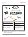
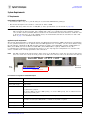
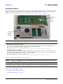
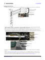
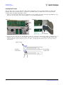
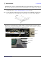
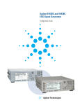
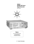
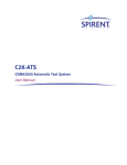
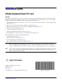
Installation Guide
N5101A Baseband Studio PCI Card
Overview
This guide provides instructions on how to install the N5101A Baseband Studio PCI card in a PC. The PCI card is
installed in a PC and is used with a signal source (or an N5515C wireless communications test set) to run Agilent
software applications. The installation process comprises the following steps:
1. Verify that the hardware you received is correct, and note the license and serial number of each Baseband Studio
PCI card (page 2).
2. Ensure that your PC meets the basic installation requirements (page 3).
3. Ensure that your signal source meets the basic installation requirements (page 5).
4. Install the PCI card hardware (page 6).
5. Connect the digital bus cable (page 11).
6. Install the Baseband Studio PCI card driver (page 12).
7. Install application software and license used with the PCI card (page 12).
This document also provides the following information:
• Troubleshooting tips (page 14)
• Agilent assistance information (page 15)
• Safety and regulatory information (page 15)
• List of additional PCI card- related documentation (page 16)
TIP
Before you start! This installation procedure provides you many options which are based on your PC,
software, and application. To minimize the chance of making a mistake, please review this document in its
entirety to understand which procedures you will be using to install the PCI card(s) for your requirements.
NOTE
If you ordered N5101A- 022 (512 MSa memory upgrade) for your PCI card(s), install the memory in the PCI
card first. Use the N5101A Baseband Studio PCI Card Memory Upgrade Installation Note (N5101- 90003)
which is packaged with the memory.
Agilent Part Number: N5101- 90005
Printed in USA
March 2007
© Copyright 2005 − 2007 Agilent Technologies, Inc.
N5101A Baseband Studio PCI Card
Installation Guide
Checking the Shipment
Checking the Shipment
For each N5101A Baseband Studio PCI card purchased, you should receive the following items:
1
Ribbon Cable (P/N 8121- 1360)
(Used only for extended path or digital input/digital
output fading using N5115A software)
5
N5101A Baseband Studio PCI Card
2
Foam Pad (P/N N5101- 20005)
(Used only when two PCI cards are installed)
6
PCI Card Extender Bracket & Screws
Retainer: P/N N5101- 00007
Screws: P/N 0515- 2087 (2 each)
3
Digital Bus Cable (P/N N5101- 60003)
7
11- hole auxiliary plate with 4 SMB cables assembly
(P/N N5101- 60015)
(Replacement SMB- to- MCX Cable: P/N 8121- 0655)
4
SMB to SMB Cables (P/N 8120- 5020) (2 each)
(Used only for two- card fading as descibed in
Three- Slot External Configuration and “Four- Slot
External Configuration for Old GPIO Brackets” on
page 13)
8
Loopback Fixture (P/N E4400- 63583)
(Used with the “Run Self- Tests” function in the
application software.)
Installation Guide (P/N N5101- 90005) not shown (this document)
NOTE
2
The PCI card is used by a variety of PCI card applications. Not all of the parts that are listed above are
required for every application or configuration. Save any unused parts in case your application changes or
you upgrade your system in the future.
N5101A Baseband Studio PCI Card
Installation Guide
System Requirements
System Requirements
PC Requirements
Requirements for All Applications
• You must be able to log on to your PC using an account with administrative privileges.
• The PC and all signal sources must be connected via LAN or GPIB.
• Available PCI slot(s) must meet the 2.2 PCI/ISA (or later) specifications (see the bottom of page 14).
NOTE
Not all computer cases are PCI or ISA compliant. PCI- compliant computer cases accommodate the N5101A
PCI card with the metal extender, thus enabling both ends to be restrained. For ISA compliant computer
cases, an ISA retainer (included) must be attached to the N5101A PCI card metal extender to enable the card
to fit into the ISA slots. To avoid reliability issues, the N5101A PCI card must be restrained on both ends.
Refer to page 6 for installation instructions.
Application-Specific Requirements
The N5110B Baseband Studio for Waveform Capture and Playback hard disk drive (HDD) playback rate and duration
are not guaranteed. Factory tests at Agilent achieved a HDD playback rate of 40 MSa/s over an 8 hour duration using
the following PC configuration: HP XW 8200 PC workstation, Adaptec 2230 SLP RAID controller, 74- GB SATA 150
HDD (10000 RPM), and four 73- GB U320 SCSI HDD (15000 RPM, RAID 0 required, 64KB block size). The
recommended PC configuration requirements listed below are the only suggested configurations for customers who
want to assemble their own high- performance PC workstation.
NOTE
The PCI card will fit into PCs that have either 32- bit or 64- bit PCI slots. 32- bit slots are shorter than 64- bit
slots. If a 32- bit slot is used, the front portion of the PCI card connector will not be inserted in the PCI slot.
Bottom Half of PCI Card
Rear
of PC
32- Bit Connector
Front of
PCI Card
64- Bit Connector
Recommended PC Configuration for N5110B HDD Playback
Processor
Pentium‚ 4, 2 GHz or greater (dual processors are recommended)
Front Side Bus
533 MHz
Memory (Size, Type)
1 GB, PC2700
Available PCI Slots
64 bit/66 MHz or 64 bit/133 MHz and one additional PCI slot opening
For dual- instance playback:
One 64 bit/66 MHz (or 64 bit/133 MHz opening), one 32 bit/33 MHz opening, and one additional PCI slot
opening using auxiliary plate
HDD Controller
Ultra 320 SCSI RAID Controller (capable of RAID 0 configuration)
Hard Disks
One SATA 150 (10000 RPM)
Four Ultra 320 SCSI (15000 RPM, RAID 0, 64 KB block size) RAID 0 required
HDD Configuration
Dedicated OS Drive, Data on RAID 0
Operating System
Windows‚ XP Professional
N5101A Baseband Studio PCI Card
3
Installation Guide
System Requirements
The table below lists the minimum PC requirements to capture or playback waveforms using the DRAM of the N5110B
Baseband Studio for Waveform Capture and Playback software.
Minimum N5110B PC Requirements for DRAM Capture and Playback
Processor
Pentium III, 800 MHz or greater
Operating System
Windows XP Professional, SP 1 or greater - or- Windows 2000 Professional, SP 3 or greater
Memory (RAM)
256 MB minimum (512 MB recommended)
Free Disk Space
200 MB minimum
Display
1024 x 768 minimum screen resolution with normal font size
Available PCI Slots
One 32 bit/33 MHz and one additional PCI slot opening
For dual- instance playback:
Two 32 bit/33 MHz opening, and one additional PCI slot opening using auxiliary plate (If a PCI slot
opening is not available for auxiliary plate, the two- slot internal configuration (page 13) using three
MCX cables (not provided) may be used.)
The table below lists the minimum PC requirements for the N5115B Baseband Studio for Fading software application.
N5115B Baseband Studio for Fading Minimum PC Requirements
Processor
Pentium IV, 2.4 GHz or greater
Memory (RAM)
384 MB (512 MB or greater recommended)
Free Disk Space
190 MB minimum (160 MB for .NET framework, 30 MB for application software)
Available PCI Slots
One 32 bit/33 MHz opening for single channel configuration
For two- PCI card fading (dual- channel, path extension, digital input/digital output capability):
Two 32 bit/33 MHz openings and one additional PCI slot opening using auxiliary plate (If a PCI slot
opening is not available for auxiliary plate, the two- slot internal configuration (page 13) using three
MCX cables (not provided) may be used.)
Display
1024 x 768 minimum screen resolution with normal font size (1280 x 1024 recommended)
Operating System
Windows XP Professional, SP 1 or greater - or- Windows 2000, SP 4 or greater
Required Software
Microsoft .NET Framework 1.1 in OS language version, SP 1 or greater
Microsoft Internet Explorer version 5.01 or greater
Microsoft Excel 2000 or later (SP 1 or greater)
The table below lists the minimum PC requirements for the N7612ASignal Studio for TD- SCDMA (LCR) software
application.
N7612A Signal Studio for TD-SCDMA (LCR)
Processor
Pentium 4, 2.4 GHz or greater
Operating System
Windows XP Professional, SP 1 or greater - or- Windows 2000 Professional, SP 4 or greater
Memory (RAM)
384 MB minimum (512 MB or higher recommended)
Free Disk Space
190 MB minimum (160 MB for Microsoft .NET Framework, 30 MB for software application)
Display
1024 x 768 minimum screen resolution with normal font size (1280 x 1024 recommended)
Available PCI Slots
One 32 bit/33 MHz and one additional PCI slot opening
Required Software
Microsoft .NET Framework 1.1 in OS language version, SP 1 or greater
Microsoft Internet Explorer version 5.01 or greater
Agilent IO Libraries Suite version 14.0 or greater
Microsoft Visual Studio (.NET integrated development environment) (Required for API programming)
4
N5101A Baseband Studio PCI Card
Installation Guide
System Requirements
The following table lists the minimum PC requirements for the N5120A Baseband Studio for CPRI RE Test software
application.
CAUTION
To install the PCI card for use with Baseband Studio for CPRI RE Test, use only the N5120A Baseband
Studio for CPRI RE Test Installation Guide (N5103- 90001) because it contains all of the instructions and
details specific to this application.
N5120A Baseband Studio for CPRI RE Test
Processor
Pentium 4, 2 GHz or greater
Operating System
Windows XP Professional, SP 1 or greater - or- Windows 2000 Professional, SP 3 or greater
Memory (RAM)
1024 MB
Free Disk Space
1024 MB minimum
Available PCI Slots
Two adjacent full- length slots; one 64- bit and one 32- bit slots or two 64- bit slots
Bus
64- bit
Required Software
Microsoft .NET Framework 1.1 in OS language version, SP 1 or greater
Microsoft Internet Explorer version 5.01 or greater
Recommended Software
Agilent 89601A Series Vector Signal Analyzer and
Agilent N7600A Signal Studio for 3GPP W- CDMA with HSDPA/HSUPA
Signal Source Requirements
The PC and signal sources must be connected via LAN or GPIB.
Requirements for Signal Sources
Application
Source Model
Source Firmware Revision
Source Options
Interface
N5110B Baseband Studio for
waveform capture and playback
E8267D
C.04.04
601 or 602
LAN or GPIB
E8267C
C.03.78 or later
602
LAN or GPIB
E4438C
C.03.74 or later
601 or 602
LAN or GPIB
E4438C
C.04.10 or later
601 or 602
LAN or GPIB
E8267C
C.03.78 or later
601 or 602
LAN or GPIB
E8267D
C.04.10 or later
601 or 602
LAN or GPIB
E5515C
E6702B:B.03.00 or later,
E6703C:C.01.00 or later, or
E6785C: C.01.00 or later
003
E5515CU Option 504
GPIB only
N5115B Baseband Studio for fading
E5515CU Option 187a
N5120A Baseband Studio for CPRI
RE Test
E4438C
C.04.10 or later
400
601 or 602
LAN or GPIB
N7612B Signal Studio for
TD- SCDMA (LCR)
E4438C
C.03.72 or later
503
601 or 602
LAN or GPIB
aE5515CU Option 187 required for W-CDMA usage only.
N5101A Baseband Studio PCI Card
5
Installation Guide
Installing the Hardware
Installing the Hardware
From the PCI card, you will need the Bar Code License Number and the Instrument (Model) Serial number. These
numbers are needed when redeeming your software license. The illustration below shows the location of these two
numbers. (The license redemption process is described in “Licensing the Software” on page 12.)
Instrument
(Model)
Serial
Number
PCI Card
Bar Code
License
Number
IMPORTANT
It is important to record and save these numbers now to avoid the need to remove your PCI card from
the computer later in the installation procedure.
• PCI Card Bar Code License Number
A bar code label displaying the license number (N5101- xxxxx- xx- xxxx- xxxxx) is affixed to the PCI card (see
above). The bar code license number is used to enable the software license.
Record the PCI card bar code license number here: ____________________________________________
• Instrument Model Serial Number
A label displaying the serial number (N5101A- USxxxxxxxx) is affixed to the reverse side of the PCI card (see
above). The serial number is also displayed on a sticker affixed to the box in which the card is packaged. The
instrument model serial number is used to track the warranty.
Record the instrument model serial number here: ____________________________________________
Power down the PC and disconnect the AC power cable.
CAUTION
NOTE
Be sure to follow ESD precautions when handling the PCI card. For more information, refer to “ESD
Information” on page 15.
The N5101A PCI card is a 64- bit card. Depending on the application, it can work in either a 32- bit or 64- bit
PCI slot. Refer to “Application- Specific Requirements” on page 3 before installing the PCI card.
Follow one of the following procedures:
• “Installing a Single PCI Card” on page 7
• “Installing Two PCI Cards” on page 8
6
N5101A Baseband Studio PCI Card
Installation Guide
Installing the Hardware
Installing a Single PCI Card
1. Connect the four cables attached to the 11- hole auxiliary plate to the appropriate connectors on the PCI card.
1 - To J10 (XCLK1)
2 - To J11 (XCLK2)
3 - To J12 (XCLK3)
To N5101A Baseband
Studio PCI Card
4 - To J13 (XREF)
J11, J12, J10, J13
N5101A Baseband
Studio PCI Card
2. For PCI- compliant computer cases, install the N5101A PCI card and the 11- hole auxiliary plate in two adjacent
PCI slots. Refer to the PC’s documentation for specific installation instructions.
3. Ensure that the metal shielding bracket of the PCI card slips into the PCI slot at the front of the case. If it does
not reach the slot, you may have an ISA- compliant computer case. For ISA- compliant cases, attach the metal
extender bracket to the PCI card shielding using the two screws provided. The extender will slip into the guides at
the front of the ISA- compliant PC case. Refer to the illustrations below.
Extender
PCI Slot
Screw (2 places)
Card Shielding
Extender
4. Secure the rear of the PCI board (the end with the digital bus connector) to the PC chassis with a mounting
screw.
5. Refer to Application- Specific Cabling on page 13 and page 14 to see if additional cabling is required for your
application. If additional cabling is required, make the required connections before returning to this procedure.
6. Reconnect the AC power cable and continue with “Connecting the Digital Bus Cable” on page 11.
N5101A Baseband Studio PCI Card
7
Installation Guide
Installing the Hardware
Installing Two PCI Cards
This procedure may be used to install two PCI cards for applications, such as Baseband Studio for capture and
playback when used for dual- instances of playback or Baseband Studio for fading when used for dual- channel,
extended path, and digital input/digital output.
1. Before you install the two PCI cards into the PCI slots of the computer, attach the foam pads approximately 1 inch
from the top of the PCI card as shown in Figure A of the following illustration.
Figure A
Figure B
PCI Card B
Foam
Pad
Back Top
1"
Front Top
Foam
Pad
PCI Card A
Foam Pads
2. Connect the two cards with two AUX IO ribbon cables (not required for dual- channel fading or dual- instances of
playback). The pin connectors for the ribbon cables are located at the top of each PCI card. Each ribbon cable
connects from the top pin connector (J4) on one card to the bottom pin connector (J5) on the other card, as
shown below.
Ribbon Cables
Top Edge
of PCI Cards
Bottom Edge
of PCI Cards
J4
8
J5
N5101A Baseband Studio PCI Card
Installation Guide
Installing the Hardware
3. Each PCI card comes with an 11- hole auxiliary plate with four cables attached. The cables on these two plates can
be consolidated onto one plate so that the entire installation only occupies three PCI slots (two PCI cards and one
plate). To do this, remove the four cables from one plate and attach them to holes 5 through 8 on the other plate.
NOTE
If you only have two available slots, you can still install two PCI cards for two- PCI card applications using
internal cabling. Refer to “Two- Slot Internal Configuration” on page 13 for details.
NOTE
If you are upgrading from one PCI card to two PCI cards and have the older GPIO plate (see figure below)
installed, remove the four SMB- to- MCX cables (not the ribbon cable) from the GPIO plate and attach them to
holes 5 through 8 of the 11- hole auxiliary plate as shown in step 5. You no longer need the GPIO plate.
4. Ensure that the metal shielding bracket of each PCI card slips into the PCI slot at the front of the case. If it does
not reach the slot, you may have an ISA- compliant computer case. For ISA- compliant cases, attach the metal
extender bracket to the PCI card shielding using the two screws provided. The extender will slip into the guides at
the front of the ISA- compliant PC case. Refer to the illustrations below.
Extender
PCI Slot
Screw (2 places)
Card Shielding
Extender
N5101A Baseband Studio PCI Card
9
Installation Guide
Installing the Hardware
5. Connect the eight cables attached to the 11- hole auxiliary plate to the appropriate connectors on the two PCI
cards, as shown below.
1 - To J10 (XCLK1)
2 - To J11 (XCLK2)
3 - To J12 (XCLK3)
4 - To J13 (XREF)
5 - To J10 (XCLK1)
6 - To J11 (XCLK2)
7 - To J12 (XCLK3)
8 - To J13 (XREF)
J11
J12
J13
J10
Connectors positioned in this
order at top of PCI Card
6. Secure the rear of both PCI cards (the end with the digital bus connector) to the PC chassis with a mounting
screw.
7. Refer to Application- Specific Cabling on page 13 and page 14 to see if additional cabling is required for your
application. If additional cabling is required, make the required connections before returning to this procedure.
8. Reconnect the AC power cable and continue with “Connecting the Digital Bus Cable” on page 11.
10
N5101A Baseband Studio PCI Card
Installation Guide
Connecting the Digital Bus Cable
Internal Cabling for Old PCI Cards with GPIO Bracket
Connect the GPIO bracket ribbon cable to J3 on the PCI card. The remaining cables can be connected, as shown,
either before or after you install the PCI card in the computer.
Number on
GPIO Bracket
PCI Card
Connector
4
J10
5
J11
6
J12
7
J3
8
J13
Number on
GPIO Bracket
4
5
6
SMB- to- MCX
Cables
J10
J13
J12
J11
7
8
Ribbon
Cable
J3
For connector visibility, the PCI card
is shown without its metal shielding.
Connecting the Digital Bus Cable
1. Inspect the digital bus cable and connectors to ensure that they are clean.
2. Connect a digital bus cable between each N5101A Baseband Studio PCI card and a source (or N5102A Baseband
Studio digital signal interface module), connecting the end of the cable with the EMI suppressor to the source.
EMI Suppressor:
Connect this end of the
cable to the source.
NOTE The digital bus cable connector has a release latch on each side. As you make a connection, you must
simultaneously squeeze these release latches (see the illustration below); the connector should snap into
place. A securely connected cable does not come loose when gently pulled.
To disconnect the cable, squeeze the release latches as you remove the connector.
3. Continue with “Installing the Software” on page 12.
N5101A Baseband Studio PCI Card
11
Installation Guide
Installing the Software
Installing the Software
Downloading the PCI Card Driver
1. Go to the Agilent Technologies website: http://www.agilent.com/find/basebandstudio.
2. Click the N5101A product link.
3. On the N5101A Baseband Studio PCI Card page, click the Baseband Studio PCI Card Driver link and follow the
download instructions.
Downloading Application Software
Go to the appropriate Agilent Technologies web page for information on downloading and installing application
software.
Go to http://www.agilent.com/find/basebandstudio for the following Baseband Studio applications:
• N5110B Baseband Studio for Waveform Capture and Playback
• N5115B Baseband Studio for Fading
• N5120A Baseband Studio for CPRI RE Test
Go to http://www.agilent.com/find/signalstudio for the following Signal Studio applications:
• N7612A Signal Studio for TD- SCDMA (LCR)
Licensing the Software
Software applications require a license file to be fully functional. Software applications are licensed to a specific PCI
card. You may license more than one application to a single PCI card.
A License Redemption Entitlement Certificate,
similar to the one shown at the right, is provided
with each Baseband Studio software purchase.
As shown, the entitlement certificate has two
of the four numbers required to obtain the
license file, the Agilent Order Number and
the Agilent Certificate Number.
The instructions at the bottom of the license
redemption entitlement certificate direct you
to go to the software license web site.
To redeem your license, you will enter the two entitlement certificate numbers and the two PCI card numbers (from
page 6) in this web site. After you have completed the redemption process, the license file and its installation
instructions will be emailed to you.
CAUTION
The bar code number on the PCI card is 21 digits in length; these 21 digits are separated by 4 hyphens
for easy reading.
When entering the PCI card bar code number, do not enter the hyphens!
12
N5101A Baseband Studio PCI Card
Installation Guide
Application-Specific Cabling
Application-Specific Cabling
N5110B Baseband Studio for Waveform Capture and Playback
The SMB connectors on the 11- hole auxiliary plate can be used for a trigger and input/output indicator signals as
described in the software’s help. In the playback mode, the software provides versatile assignment of the signals to the
SMB connectors. In the capture mode, the trigger signal uses SMB connector 1 on the 11- hole auxiliary plate (SMB
connector 4 on the older GPIO bracket).
If two PCI cards are used for dual- instance playback, the cards are independent of each other. They do not require
being connected to each other like the 2- PCI card fading applications.
N5115B Baseband Studio for Fading, 2 PCI Card
Three-Slot External Configuration
Connect three SMB- to- SMB cables between the following connectors on the 11- hole auxiliary plate.
• Connector 1 to Connector 8
• Connector 2 to Connector 4
• Connector 3 to Connector 5
Two-Slot Internal Configuration
If you are using two PCI cards for fading and your PC has only two open PCI slots, you can connect the PCI cards
internally using three MCX- to- MCX cables (Agilent part number 8121- 0620). These cables are not provided with the
PCI card. The cables have MCX (male) connectors on both ends and are connected as shown below.
•
Master Connector J13 to Master Connector J11
•
Master Connector J10 to Slave Connector J13
•
Master Connector J12 to Slave Connector J11
NOTE
Connectors J10 and J12 of slave card do not
require cabling and are left open.
Slave PCI Card
Master PCI Card
J11 J12 J10 J13
Four-Slot External Configuration for Old GPIO Brackets
This section applies only to the old- style GPIO brackets used in previous versions of N5101A PCI cards. Connect three
SMB- to- SMB cables between the following connectors on the GPIO bracket.
•
Master Connector 4 to Slave Connector 8
•
Master Connector 5 to Master Connector 8
•
Master Connector 6 to Slave Connector 5
Slave
Master
N5101A Baseband Studio PCI Card
13
Installation Guide
Troubleshooting
N5120A Baseband Studio for CPRI RE Test
For cabling information, refer to the N5120A software’s help and the N5120A Baseband Studio for CPRI RE Test
Installation Guide (N5103- 90001).
N7612A Signal Studio for TD-SCDMA (LCR)
The SMB connectors on the 11- hole auxiliary plate accept an input trigger (SMB connector 1) and provide two output
markers (SMB connectors 2 and 3). (If the GPIO bracket is being used, the input trigger is SMB connector 4 and the
two output markers are SMB connectors 5 and 6.) For details, refer to the software’s help.
Troubleshooting
The Found New Hardware wizard is not displayed
If an N5101A Baseband Studio PCI card was previously installed, you may see a slightly different dialog from the New
Hardware Detected wizard. If this happens, select the file N5101A.sys from the driver directory on the Baseband
Studio CD, rather than the N5101A.inf file.
No prompt for the N5101A Baseband Studio PCI card driver
If you are not prompted for the N5101A Baseband Studio card driver, turn off the PC and ensure that the PCI card is
securely seated in its slot. Reboot the PC, and log on using an account with administrative privileges.
N5101A Baseband Studio PCI card does not appear in the IO Config utility under "Select an N5101A"
Ensure that all N5101A Baseband Studio PCI cards are installed correctly:
1. On the PC desktop, right- click the My Computer icon.
2. Select Properties.
3. Click the Hardware tab.
4. Click Device Manager.
Under Agilent Technologies Test & Measurement Devices, you should see at least one Agilent N5101A listed.
5. Right- click an Agilent Technologies N5101A icon and select Properties.
In the Device status area, you should see the message, “This device is working properly.” If not, the
N5101A Baseband Studio PCI card is probably not seated properly in the PC.
N5101A PCI Card-PC Installation Compatibility Issues
• PCI Long Card
Some PCs will have front card guides in the plane of the N5101A PCB which will support the front edge of the
metal extension plate on the N5101A card. These front card guide slots will be about 305 mm (12 inches) from the
rear card mounting surface and in line with the PCI connector. The N5101A PCB with the installed front metal
plate is compliant with the PCI long card specification. The overall card length is 312 mm (12.283 inches).
• ISA Long Card
Some PCs will have ISA- compliant front card guides. These ISA front card guide slots will be about 335 mm
(13 inches) from the rear card mounting surface and offset from the plane of the N5101A PCB and PCI connector
by 14.27 mm (0.562 inches). An ISA retainer (an adaptor with two mounting screws) must be installed onto the
N5101A metal extension plate to support the front of the card.
• PC Slot Too Short for N5101A PCI Card
The N5101A front metal extension plate may be removed. If the PC slots are still too short, a PC with PCI or ISA
long card compliant slots is recommended.
14
N5101A Baseband Studio PCI Card
Installation Guide
Getting Assistance from Agilent
Getting Assistance from Agilent
Your local Agilent office can help you with your test and measurement needs. The following Internet URL provides the
information you need to contact your local Agilent office: http://www.agilent.com/find/assist
If you do not have access to the Internet, please contact your field engineer.
NOTE
In any correspondence or telephone conversation, refer to the product by its model number and full serial
number. With this information, the Agilent representative can determine whether your product is still within
its warranty period.
Safety and Regulatory Information
NOTE
A declaration of conformity is on file for the N5101A Baseband Studio PCI card and is available upon
request.
ESD Information
Protection from Electrostatic Discharge
Electrostatic discharge (ESD) can damage or destroy electronic components. All work on electronic assemblies should
be performed at a static- safe workstation using two types of static- safe workstation protection:
• conductive table- mat and wrist- strap combination
• conductive floor- mat and heel- strap combination
Both types, when used together, provide a significant level of ESD protection. Of the two types, only the table- mat and
wrist- strap combination provides adequate ESD protection when used alone. To ensure user safety, the static- safe
accessories must provide at least 1 MW of isolation from ground.
Handling of Electronic Components and ESD
CAUTION
Many printed circuit (PC) boards are very susceptible to damage from electrostatic discharge (ESD).
Always handle a PC board assembly by the edges at a static- safe workstation while wearing a grounding
strap. Handling the PC board only by the edges will reduce the possibility of ESD damage to the
components and prevent contamination of exposed plating.
The possibility of unseen damage caused by ESD is present whenever components are transported, stored, or used.
The risk of ESD damage can be greatly reduced by close attention to how all components are handled.
• Perform work on all components at a static- safe workstation.
• Keep static generating materials at least one meter away from all components.
• Store or transport components in static- shielded containers.
N5101A Baseband Studio PCI Card
15
Installation Guide
Additional PCI Card-Related Documentation
Additional PCI Card-Related Documentation
The following list of PCI card- related documentation is available from the Agilent website (http://www.agilent.com).
The easiest method of finding this documentation is using the Agilent web site search tool to search for the document
part number.
• N5101A Baseband Studio PCI Card Memory Upgrade Installation Note
Agilent part number: N5101- 90003
• N5120A Baseband Studio for CPRI RE Test Installation Guide
Agilent part number: N5103- 90001
• N5102A Baseband Studio Digital Signal Interface Module Installation Guide
Agilent part number: N5102- 90003
• E5515C Fading Solution Application Guide
Agilent part number: 1000- 1894
http://cp.literature.agilent.com/litweb/pdf/1000- 1894.pdf
WEEE Directive
This product complies with the WEEE Directive (2002/96/EC) marking requirements. The
affixed label indicates that you must not discard this electrical/electronic product in
domestic household waste.
Product Category: With reference to the equipment types in the WEEE Directive Annex 1,
this product is classed as a “Monitoring and Control instrumentation” product.
Do not dispose in domestic household waste.
To return unwanted products, contact your local Agilent office, or see
http://www.agilent.com/environment/product/ for more information.
Acknowledgements
Pentium is a U.S. registered trademark of Intel Corporation.
Microsoft is a U.S. registered trademark of Microsoft Corporation.
Windows is a U.S. registered trademark of Microsoft Corporation.
16
N5101A Baseband Studio PCI Card