1
Electric Drives
and Controls
Hydraulics
Linear Motion and
Assembly Technologies
Pneumatics
Service
Bosch Rexroth AG | Electric Drives
and Controls
Title
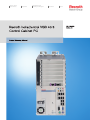
Rexroth IndraControl VSB 40.3 | Project Planning Manual
Rexroth IndraControl VSB 40.3
Control Cabinet PC
Type of Documentation
Document Typecode
Internal File Reference
Purpose of Documentation
Record of Revision
Copyright
Project Planning Manual
DOK-SUPPL*-VSB*40.3***-PR03-EN-P
RS-fd54ee2fa17e016b0a6846a000dcf303-3-en-US-5
This documentation describes the control cabinet PC VSB 40.3.
Edition
Release Date
Notes
120-2101-B302-01/EN
04.2008
First edition
120-2101-B302-02/EN
03.2009
Second edition
120-2101-B302-03/EN
08.2009
Third edition
© Bosch Rexroth AG, 2008
Copying this document, giving it to others and the use or communication of the
contents thereof without express authority, are forbidden. Offenders are liable
for the payment of damages. All rights are reserved in the event of the grant of
a patent or the registration of a utility model or design (DIN 34-1).
Validity
Published by
The specified data is for product description purposes only and may not be
deemed to be guaranteed unless expressly confirmed in the contract. All rights
are reserved with respect to the content of this documentation and the availa‐
bility of the product.
Bosch Rexroth AG
Bgm.-Dr.-Nebel-Str. 2 ■ 97816 Lohr am Main, Germany
Phone +49 (0)93 52/ 40-0 ■ Fax +49 (0)93 52/ 40-48 85
http://www.boschrexroth.com/
Dept. DCC/EAY2 (CS)
Dept. DCC/EAP1 (HG/CS)
Note
This document has been printed on chlorine-free bleached paper.
Project Planning Manual | Rexroth IndraControl VSB 40.3
Electric Drives | Bosch Rexroth AG
and Controls
I/IV
Table of Contents
Table of Contents
Page
1
1.1
1.2
1.3
2
2.1
2.1.1
2.1.2
2.2
3
3.1
3.2
3.2.1
3.2.2
3.2.3
3.2.4
3.3
3.3.1
3.3.2
3.3.3
3.3.4
3.3.5
3.3.6
3.3.7
3.3.8
4
4.1
4.2
4.3
4.4
4.4.1
4.4.2
4.4.3
4.5
4.6
5
5.1
System Presentation...................................................................................................... 5
Brief Description VSB 40.3..................................................................................................................... 5
Operating System................................................................................................................................... 6
Commissioning....................................................................................................................................... 6
Important Instructions on Use ....................................................................................... 7
Appropriate Use ..................................................................................................................................... 7
Introduction.......................................................................................................................................... 7
Areas of Use and Application.............................................................................................................. 7
Inappropriate Use................................................................................................................................... 8
Safety Instructions for Electric Drives and Controls ...................................................... 9
Definitions of Terms................................................................................................................................ 9
General Information.............................................................................................................................. 10
Using the Safety Instructions and Passing Them on to Others......................................................... 10
Requirements for Safe Use............................................................................................................... 10
Hazards by Improper Use.................................................................................................................. 11
Explanation of Safety Symbols and Hazard Classification................................................................ 12
Instructions with Regard to Specific Dangers....................................................................................... 12
Protection Against Contact with Electrical Parts and Housings......................................................... 12
Protective Extra-Low Voltage as Protection Against Electric Shock ................................................ 13
Protection Against Dangerous Movements....................................................................................... 14
Protection Against Magnetic and Electromagnetic Fields During Operation and Mounting.............. 16
Protection Against Contact with Hot Parts......................................................................................... 16
Protection During Handling and Mounting......................................................................................... 17
Battery Safety.................................................................................................................................... 17
Protection Against Pressurized Systems........................................................................................... 17
Technical Data............................................................................................................. 19
PC Box.................................................................................................................................................. 19
Technical Data of the 24 V Voltage Supply 200 W .............................................................................. 19
Ambient Conditions............................................................................................................................... 20
Standards............................................................................................................................................. 21
Used Standards................................................................................................................................. 21
CE Marking........................................................................................................................................ 21
Declaration of Conformity .............................................................................................................. 21
Note for the Machine Manufacturer................................................................................................ 22
UL/CSA Certified............................................................................................................................... 22
Wear Parts............................................................................................................................................ 22
Compatibility Test................................................................................................................................. 23
Dimensions, Installation and Wiring............................................................................. 25
General Information.............................................................................................................................. 25
II/IV
Bosch Rexroth AG | Electric Drives
and Controls
Rexroth IndraControl VSB 40.3 | Project Planning Manual
Table of Contents
Page
5.2
5.3
5.4
6
6.1
6.2
6.2.1
6.2.2
6.2.3
7
7.1
7.2
7.2.1
7.2.2
7.2.3
7.2.4
7.2.5
7.2.6
7.2.7
7.2.8
7.2.9
7.2.10
7.2.11
7.2.12
7.2.13
8
8.1
8.2
8.3
8.3.1
8.3.2
8.4
8.4.1
8.4.2
9
9.1
9.2
9.2.1
9.2.2
9.2.3
Installation Dimensions of the VSB 40.3 .............................................................................................. 27
Installation Notes.................................................................................................................................. 28
Wiring.................................................................................................................................................... 29
Display and Operating Components............................................................................ 33
Power Button........................................................................................................................................ 33
Display, Monitor and Keyboard............................................................................................................. 33
Display............................................................................................................................................... 33
VGA Monitor...................................................................................................................................... 33
Selection of the Graphics Driver........................................................................................................ 33
PC Box......................................................................................................................... 37
View on the Connector Panel .............................................................................................................. 37
Interfaces.............................................................................................................................................. 37
General Information........................................................................................................................... 37
Overview............................................................................................................................................ 37
PC Voltage Supply............................................................................................................................ 38
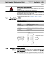
Serial Interface XCOM ...................................................................................................................... 39
Settings of the Serial Interface.......................................................................................................... 39
XUSB Interfaces................................................................................................................................ 40
Ethernet Interface XLAN.................................................................................................................... 40
XVGA Interface.................................................................................................................................. 41
Keyboard Interface XKB.................................................................................................................... 42
Mouse Interface XMouse................................................................................................................... 42
CDI Interface..................................................................................................................................... 43
Audio Interface XAudio...................................................................................................................... 44
Connection of a UPS......................................................................................................................... 44
UPS with USB Interface................................................................................................................. 44
Maintenance and Installation....................................................................................... 47
General Information.............................................................................................................................. 47
CMOS Battery....................................................................................................................................... 47
Hard Disk.............................................................................................................................................. 48
General Information........................................................................................................................... 48
Exchanging the Hard Disk of the VSB 40.3....................................................................................... 48
Extension Cards................................................................................................................................... 51
General Information........................................................................................................................... 51
Inserting Extension Card................................................................................................................... 51
Software....................................................................................................................... 55
Windows XP Multi-User-Interface (MUI)............................................................................................... 55
Data backup with Acronis True Image Echo Workstation..................................................................... 56
Introduction........................................................................................................................................ 56
System Presentation......................................................................................................................... 57
Acronis Secure Zone und Startup Recovery Manager...................................................................... 59
Project Planning Manual | Rexroth IndraControl VSB 40.3
Electric Drives | Bosch Rexroth AG
and Controls
III/IV
Table of Contents
Page
9.2.4
9.2.5
9.2.6
9.2.7
9.2.8
9.2.9
9.2.10
9.2.11
9.2.12
9.3
9.3.1
9.3.2
9.3.3
9.4
9.4.1
9.4.2
9.4.3
9.4.4
9.4.5
9.4.6
9.5
9.5.1
9.5.2
9.6
9.7
9.8
9.9
9.10
9.10.1
9.10.2
9.11
9.11.1
9.11.2
9.11.3
10
10.1
10.2
11
11.1
11.2
11.2.1
11.2.2
11.2.3
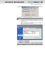
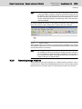
Creating Image Archives .................................................................................................................. 60
Validating Image Archives ................................................................................................................ 63
Update and Extend Image Archives.................................................................................................. 63
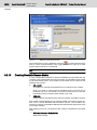
Restoring Image Archives ................................................................................................................ 64
Exploring Image Archives.................................................................................................................. 66
Removing Image Archives ................................................................................................................ 67
Creating Bootable Rescue Media...................................................................................................... 68
Network Support................................................................................................................................ 69
Planning Tasks.................................................................................................................................. 69
Software for UPS Monitoring ............................................................................................................... 71
General Information........................................................................................................................... 71
Configuration..................................................................................................................................... 72
Installation Notes............................................................................................................................... 74
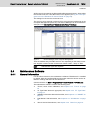
Maintenance Software.......................................................................................................................... 75
General Information........................................................................................................................... 75
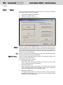
Touch................................................................................................................................................. 76
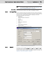
El. Type Plate.................................................................................................................................... 77
SMART.............................................................................................................................................. 77
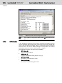
HW Monitor........................................................................................................................................ 78
About................................................................................................................................................. 79
Simulation of the Right Mouse Button.................................................................................................. 79
General Information........................................................................................................................... 79
Function............................................................................................................................................. 80
IPC Service Program............................................................................................................................ 80
USB Connection................................................................................................................................... 81
Autologin............................................................................................................................................... 82
Analog VGA Monitor............................................................................................................................. 82
M-Key-UpperClassFilter....................................................................................................................... 82
General Information........................................................................................................................... 82
Activating and Deactivating the M-Key-UpperClassFilter.................................................................. 82
RAID..................................................................................................................................................... 82
General Information........................................................................................................................... 82
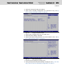
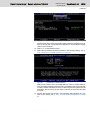
Installing RAID1 System in the BIOS................................................................................................ 82
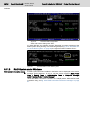
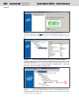
RAID System under Windows........................................................................................................... 86
Environmental Protection and Disposal ...................................................................... 89
Environmental Protection...................................................................................................................... 89
Disposal................................................................................................................................................ 89
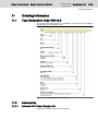
Ordering Information.................................................................................................... 91
Type Designation Code VSB 40.3........................................................................................................ 91
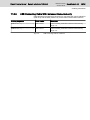
Accessories.......................................................................................................................................... 91
External 24 V Power Supply Unit...................................................................................................... 91
External UPS with USB Communication Interface............................................................................ 92
Connecting Cable for the CDI Interface............................................................................................. 92
IV/IV
Bosch Rexroth AG | Electric Drives
and Controls
Rexroth IndraControl VSB 40.3 | Project Planning Manual
Table of Contents
Page
11.2.4
11.2.5
12
USB Connecting Cable...................................................................................................................... 92
USB Connecting Cable With Increased Noise Immunity................................................................... 93
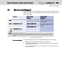
Service and Support.................................................................................................... 95
Index............................................................................................................................ 97
Project Planning Manual | Rexroth IndraControl VSB 40.3
Electric Drives | Bosch Rexroth AG
and Controls
5/101
System Presentation
1
System Presentation
1.1
Brief Description VSB 40.3
The VSB 40.3 is a control cabinet PC that forms a PC-based operator terminal
when combined with a VDP 16.3 or VDP 40.3 display. Depending on the ap‐
plication and configuration, the operator terminal can also fulfill control func‐
tionalities.
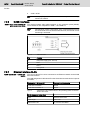
Fig.1-1:
VSB 40.3
The VSB 40.3 is connected with an operator display VDP 16.3 or VDP 40.3 via
a connecting cable of up to 80 m to the serial CDI display interface. Thus, the
VSB 40.3 can be installed in the control cabinet and the operating display in its
door or at the machine.
6/101
Bosch Rexroth AG | Electric Drives
and Controls
Rexroth IndraControl VSB 40.3 | Project Planning Manual
System Presentation
1.2
Operating System
Due to license reasons, the VSB 40.3 devices are only delivered with already
installed operating system.
1.3
Commissioning
Mount the device properly (see chapter 5 "Dimensions, Installation and Wir‐
ing" on page 25). Then, connect the device to the UPS and, if required, to the
network.
Project Planning Manual | Rexroth IndraControl VSB 40.3
Electric Drives | Bosch Rexroth AG
and Controls
7/101
Important Instructions on Use
2
Important Instructions on Use
2.1
Appropriate Use
2.1.1
Introduction
Rexroth products represent state-of-the-art developments and manufacturing.
They are tested prior to delivery to ensure operational safety and reliability.
Physical injury and material damage might result from inappropriate use
of the products!
WARNING
The products are designed for use in an industrial environment and may there‐
fore only be used for the intended purpose. If they are not used as intended,
situations causing personal injury as well as material damage can occur.
Rexroth disclaims as manufacturer any warranty, liability or dam‐
ages occurring due to inappropriate use of the products. Further‐
more, Rexroth is not paying any compensation. The user is
responsible for any risks resulting from inappropriate use of the
products.
Before using Rexroth products, the following requirements must be met to en‐
sure appropriate use of the products:
2.1.2
●
Anyone handling one of the Rexroth products in any way has to read and
understand the respective safety-related guidelines as well as the instruc‐
tions on appropriate use.
●
Hardware products have to remain in their original state, in other words,
no modification regarding the design are allowed. Software products must
not be decompiled and their source codes must not be modified.
●
Damaged or faulty products must not be implemented or put into opera‐
tion.
●
It must be ensured that the products are installed as specified in the doc‐
umentation.
Areas of Use and Application
The VSB 40.3 by Rexroth is a control cabinet PC and becomes a PC-based
operator terminal when used with a VDP display. Depending on the application
and configuration, control functionality can also be carried out.
The VSB 40.3 may only be used with the accessories and add-on
components specified in this documentation. Components that are
not mentioned explicitly must neither be mounted nor connected.
The same is applicable for cables and wires.
Operation may only be carried out in the component configurations
and combinations specified and with the software and firmware
specified in the respective functional description.
Typical areas of application of the VSB 40.3 are:
●
Handling systems and assembly systems
●
Packaging and processing machines
●
Printing machines and paper processing machines
●
Machine tools
8/101
Bosch Rexroth AG | Electric Drives
and Controls
Rexroth IndraControl VSB 40.3 | Project Planning Manual
Important Instructions on Use
●
Wood working machines
The VSB 40.3 may only be operated under the assembly conditions and in‐
stallation conditions, in the specified position of application and under the
specified ambient conditions (temperature, degree of protection, humidity, EMC
etc.) given in this documentation.
2.2
Inappropriate Use
The application of control cabinet PC that are VSB 40.3 not within the specified
areas of application or under operating conditions deviating from the operating
conditions and technical data specified in the documentation is considered as
"inappropriate".
control cabinet PC VSB 40.3 may not be used if ...
●
it is exposed to operating conditions that do not fulfill the ambient condi‐
tions specified (for example, operation under water, under extreme tem‐
perature fluctuations or extreme maximum temperatures is not allowed);
●
Rexroth has not explicitly released the intended applications – please also
note the general statements in the general safety-related guidelines;
Project Planning Manual | Rexroth IndraControl VSB 40.3
Electric Drives | Bosch Rexroth AG
and Controls
9/101
Safety Instructions for Electric Drives and Controls
3
Safety Instructions for Electric Drives and Controls
3.1
Definitions of Terms
Application Documentation
The entire documentation used to inform the user of the product about the use
and safety-relevant features for configuring, integrating, installing, mounting,
commissioning, operating, maintaining, repairing and decommissioning the
product. The following terms are also used for this kind of documentation: User
Guide, Operation Manual, Commissioning Manual, Instruction Manual, Project
Planning Manual, Application Manual, etc.
Component
Combination of elements with a specified function, which are part of a piece of
equipment, device or system. Components of a drive and control system are,
for example, supply units, drive controllers, mains choke, mains filter, motors,
cables, etc.
Control System
Several interconnected control components placed on the market as a single
functional unit.
Device
Finished product with a defined function, intended for users and placed on the
market as an individual piece of merchandise.
Drive System
A group of components consisting of electric motor(s), motor encoder(s) and
cable(s), supply units and drive controllers, as well as possible auxiliary and
additional components, such as mains filter, mains choke, etc.
Electrical Equipment
Objects used to generate, convert, transmit, distribute or apply electrical ener‐
gy, such as machines, transformers, switching devices, cables, lines, powerconsuming devices, circuit board assemblies, plug-in units, control cabinets,
etc.
Installation
Several devices or systems interconnected for a defined purpose and on a de‐
fined site which, however, are not intended to be placed on the market as a
single functional unit.
Machine
Entirety of interconnected parts or units at least one of which is movable. Thus,
a machine consists of the appropriate machine drive elements, as well as con‐
trol and power circuits, which have been assembled for a specific application.
A machine is, for example, intended for processing, treatment, movement or
packaging of a material. The term "machine" also covers a combination of ma‐
chines which are arranged and controlled in such a way that they function as a
unified whole.
Manufacturer
Individual or legal entity bearing responsibility for the design and manufacture
of a product which is placed on the market in the individual's or legal entity's
name. The manufacturer can use finished products, finished parts or finished
elements, or contract out work to subcontractors. However, he must always
have overall control and possess the required authority to take responsibility
for the product.
Product
Produced device, component, part, system, software, firmware, among other
things.
Project Planning Manual
Part of the application documentation used to support the dimensioning and
planning of systems, machines or installations.
Qualified Persons
In terms of this application documentation, qualified persons are those persons
who are familiar with the installation, mounting, commissioning and operation
of the components of the drive and control system, as well as with the hazards
this implies, and who possess the qualifications their work requires. To comply
with these qualifications, it is necessary, among other things,
●
to be trained, instructed or authorized to switch electric circuits and devi‐
ces safely on and off, to ground them and to mark them,
10/101
Bosch Rexroth AG | Electric Drives
and Controls
Rexroth IndraControl VSB 40.3 | Project Planning Manual
Safety Instructions for Electric Drives and Controls
User
●
to be trained or instructed to maintain and use adequate safety equipment,
●
to attend a course of instruction in first aid.
A person installing, commissioning or using a product which has been placed
on the market.
3.2
General Information
3.2.1
Using the Safety Instructions and Passing Them on to Others
Do not attempt to install and operate the electric components of the drive and
control system without first reading all documentation provided with the product.
Read and understand these safety instructions and all user documentation prior
to working with these components. If you do not have the user documentation
for the components, contact your responsible Bosch Rexroth sales partner. Ask
for these documents to be sent immediately to the person or persons respon‐
sible for the safe operation of the components.
If the component is resold, rented and/or passed on to others in any other form,
these safety instructions must be delivered with the component in the official
language of the user's country.
WARNING
Improper use of these components, failure to follow the safety instruc‐
tions in this document or tampering with the product, including disabling
of safety devices, could result in property damage, injury, electric shock
or even death.
Observe the safety instructions!
3.2.2
Requirements for Safe Use
Read the following instructions before initial commissioning of the electric com‐
ponents of the drive and control system in order to eliminate the risk of injury
and/or property damage. You must follow these safety instructions.
●
Bosch Rexroth is not liable for damages resulting from failure to observe
the safety instructions.
●
Read the operating, maintenance and safety instructions in your language
before commissioning. If you find that you cannot completely understand
the application documentation in the available language, please ask your
supplier to clarify.
●
Proper and correct transport, storage, mounting and installation, as well
as care in operation and maintenance, are prerequisites for optimal and
safe operation of the component.
●
Only qualified persons may work with components of the drive and control
system or within its proximity.
●
Only use accessories and spare parts approved by Bosch Rexroth.
●
Follow the safety regulations and requirements of the country in which the
electric components of the drive and control system are operated.
●
Only use the components of the drive and control system in the manner
that is defined as appropriate. See chapter "Appropriate Use".
●
The ambient and operating conditions given in the application documen‐
tation at hand must be observed.
●
Safety-relevant applications are only allowed if clearly and explicitly speci‐
fied in the application documentation "Integrated Safety Technology". If
Project Planning Manual | Rexroth IndraControl VSB 40.3
Electric Drives | Bosch Rexroth AG
and Controls
11/101
Safety Instructions for Electric Drives and Controls
this is not the case, they are excluded. Safety-relevant are all such appli‐
cations which can cause danger to persons and property damage.
●
The information given in the application documentation with regard to the
use of the delivered components contains only examples of applications
and suggestions.
The machine and installation manufacturer must
–
make sure that the delivered components are suited for his individual
application and check the information given in this application docu‐
mentation with regard to the use of the components,
–
make sure that his individual application complies with the applicable
safety regulations and standards and carry out the required meas‐
ures, modifications and complements.
●
Commissioning of the delivered components is only allowed once it is sure
that the machine or installation in which the components are installed
complies with the national regulations, safety specifications and standards
of the application.
●
Operation is only allowed if the national EMC regulations for the applica‐
tion are met.
●
The instructions for installation in accordance with EMC requirements can
be found in the section on EMC in the respective application documenta‐
tion.
The machine or installation manufacturer is responsible for compliance
with the limit values as prescribed in the national regulations.
●
The technical data, connection and installation conditions of the compo‐
nents are specified in the respective application documentations and must
be followed at all times.
National regulations which the user must take into account
●
European countries: According to European EN standards
●
United States of America (USA):
–
National Electrical Code (NEC)
–
National Electrical Manufacturers Association (NEMA), as well as
local engineering regulations
–
Regulations of the National Fire Protection Association (NFPA)
●
Canada: Canadian Standards Association (CSA)
●
Other countries:
–
International Organization for Standardization (ISO)
–
International Electrotechnical Commission (IEC)
3.2.3
Hazards by Improper Use
●
High electrical voltage and high working current! Danger to life or serious
injury by electric shock!
●
High electrical voltage by incorrect connection! Danger to life or injury by
electric shock!
●
Dangerous movements! Danger to life, serious injury or property damage
by unintended motor movements!
●
Health hazard for persons with heart pacemakers, metal implants and
hearing aids in proximity to electric drive systems!
●
Risk of burns by hot housing surfaces!
12/101
Bosch Rexroth AG | Electric Drives
and Controls
Rexroth IndraControl VSB 40.3 | Project Planning Manual
Safety Instructions for Electric Drives and Controls
3.2.4
●
Risk of injury by improper handling! Injury by crushing, shearing, cutting,
hitting!
●
Risk of injury by improper handling of batteries!
●
Risk of injury by improper handling of pressurized lines!
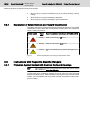
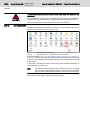
Explanation of Safety Symbols and Hazard Classification
The safety instructions describe the following hazard classification. The hazard
classification informs about the consequences resulting from non-compliance
with the safety instructions:
Safety symbol
Fig.3-1:
Signal
word
Hazard classification according to ANSI Z535.4-2002
Danger
Death or serious injury will occur.
Warning
Death or serious injury could occur.
Caution
Minor or moderate injury or property damage may oc‐
cur.
Hazard Classification (According to ANSI Z535.4-2002)
3.3
Instructions with Regard to Specific Dangers
3.3.1
Protection Against Contact with Electrical Parts and Housings
This section concerns components of the drive and control system
with voltages of more than 50 volts.
Contact with parts conducting voltages above 50 volts can cause personal
danger and electric shock. When operating components of the drive and control
system, it is unavoidable that some parts of these components conduct dan‐
gerous voltage.
Project Planning Manual | Rexroth IndraControl VSB 40.3
Electric Drives | Bosch Rexroth AG
and Controls
13/101
Safety Instructions for Electric Drives and Controls
High electrical voltage! Danger to life, risk of injury by electric shock or
serious injury!
WARNING
●
Only qualified persons are allowed to operate, maintain and/or repair the
electric components of the drive and control system.
●
Follow the general installation and safety regulations when working on
power installations.
●
Before switching on, the equipment grounding conductor must have been
permanently connected to all electric components in accordance with the
connection diagram.
●
Even for brief measurements or tests, operation is only allowed if the
equipment grounding conductor has been permanently connected to the
points of the components provided for this purpose.
●
Before accessing electrical parts with voltage potentials higher than 50 V,
you must disconnect electric components from the mains or from the pow‐
er supply unit. Secure the electric component from reconnection.
●
With electric components, observe the following aspects:
Always wait 30 minutes after switching off power to allow live capacitors
to discharge before accessing an electric component. Measure the elec‐
trical voltage of live parts before beginning to work to make sure that the
equipment is safe to touch.
●
Install the covers and guards provided for this purpose before switching
on.
●
Never touch electrical connection points of the components while power
is turned on.
●
Do not remove or plug in connectors when the component has been pow‐
ered.
●
As a basic principle, residual-current-operated circuit-breakers cannot be
used for electric drives to prevent direct contact.
●
Secure built-in devices from penetrating foreign objects and water, as well
as from direct contact, by providing an external housing, for example a
control cabinet.
High housing voltage and high leakage current! Danger to life, risk of
injury by electric shock!
WARNING
3.3.2
●
Before switching on and before commissioning, ground or connect the
components of the drive and control system to the equipment grounding
conductor at the grounding points.
●
Connect the equipment grounding conductor of the components of the
drive and control system permanently to the main power supply at all
times. The leakage current is greater than 3.5 mA.
●
Establish an equipment grounding connection with a copper wire of a
cross section of at least 10 mm2 (8 AWG) or additionally run a second
equipment grounding conductor of the same cross section as the original
equipment grounding conductor.
Protective Extra-Low Voltage as Protection Against Electric Shock
Protective extra-low voltage is used to allow connecting devices with basic in‐
sulation to extra-low voltage circuits.
All connections and terminals with voltages between 5 and 50 volts at the com‐
ponents of the Bosch Rexroth drive and control system are PELV ("Protec‐
tive Extra-Low Voltage") systems. It is allowed to connect devices equipped
14/101
Bosch Rexroth AG | Electric Drives
and Controls
Rexroth IndraControl VSB 40.3 | Project Planning Manual
Safety Instructions for Electric Drives and Controls
with basic insulation (such as programming devices, PCs, notebooks, display
units) to these connections.
Danger to life, risk of injury by electric shock! High electrical voltage by
incorrect connection!
WARNING
3.3.3
If extra-low voltage circuits of devices containing voltages and circuits of more
than 50 volts (e.g., the mains connection) are connected to Bosch Rexroth
products, the connected extra-low voltage circuits must comply with the re‐
quirements for PELV ("Protective Extra-Low Voltage").
Protection Against Dangerous Movements
Dangerous movements can be caused by faulty control of connected motors.
Some common examples are:
●
Improper or wrong wiring or cable connection
●
Operator errors
●
Wrong input of parameters before commissioning
●
Malfunction of sensors and encoders
●
Defective components
●
Software or firmware errors
These errors can occur immediately after equipment is switched on or even
after an unspecified time of trouble-free operation.
The monitoring functions in the components of the drive and control system will
normally be sufficient to avoid malfunction in the connected drives. Regarding
personal safety, especially the danger of injury and/or property damage, this
alone cannot be relied upon to ensure complete safety. Until the integrated
monitoring functions become effective, it must be assumed in any case that
faulty drive movements will occur. The extent of faulty drive movements de‐
pends upon the type of control and the state of operation.
Project Planning Manual | Rexroth IndraControl VSB 40.3
Electric Drives | Bosch Rexroth AG
and Controls
15/101
Safety Instructions for Electric Drives and Controls
Dangerous movements! Danger to life, risk of injury, serious injury or
property damage!
WARNING
●
A risk assessment must be prepared for the installation or machine, with
its specific conditions, in which the components of the drive and control
system are installed. As a result of the risk assessment, the user must
provide for monitoring functions and higher-level measures on the instal‐
lation side for personal safety. The safety regulations applicable to the
installation or machine must be taken into consideration. Unintended ma‐
chine movements or other malfunctions are possible if safety devices are
disabled, bypassed or not activated.
To avoid accidents, injury and/or property damage:
●
Keep free and clear of the machine’s range of motion and moving machine
parts. Prevent personnel from accidentally entering the machine’s range
of motion by using, for example:
–
Safety fences
–
Safety guards
–
Protective coverings
–
Light barriers
●
Make sure the safety fences and protective coverings are strong enough
to resist maximum possible kinetic energy.
●
Mount emergency stop switches in the immediate reach of the operator.
Before commissioning, verify that the emergency stop equipment works.
Do not operate the machine if the emergency stop switch is not working.
●
Prevent unintended start-up. Isolate the drive power connection by means
of an emergency stop circuit or use a safe starting lockout.
●
Make sure that the drives are brought to a safe standstill before accessing
or entering the danger zone.
●
Additionally secure vertical axes against falling or dropping after switching
off the motor power by, for example,
–
mechanically securing the vertical axes,
–
adding an external braking/arrester/clamping mechanism or
–
ensuring sufficient equilibration of the vertical axes.
●
The standard equipment motor holding brake or an external holding brake
controlled by the drive controller is not sufficient to guarantee personal
safety!
●
Disconnect electrical power to the components of the drive and control
system using the master switch and secure them from reconnection for:
●
–
Maintenance and repair work
–
Cleaning of equipment
–
Long periods of discontinued equipment use
Prevent the operation of high-frequency, remote control and radio equip‐
ment near electric/electronic components of the drive and control system
and their supply leads. If the use of these devices cannot be avoided,
check the machine or installation, before initial commissioning of the drive
and control system, for possible malfunctions when operating such highfrequency, remote control and radio equipment in its possible positions of
normal use. It might possibly be necessary to perform a special electro‐
magnetic compatibility (EMC) test.
16/101
Bosch Rexroth AG | Electric Drives
and Controls
Rexroth IndraControl VSB 40.3 | Project Planning Manual
Safety Instructions for Electric Drives and Controls
3.3.4
Protection Against Magnetic and Electromagnetic Fields During Oper‐
ation and Mounting
Magnetic and electromagnetic fields generated by current-carrying conductors
or permanent magnets of electric motors represent a serious danger to persons
with heart pacemakers, metal implants and hearing aids.
Health hazard for persons with heart pacemakers, metal implants and
hearing aids in proximity to electric components!
WARNING
3.3.5
●
Persons with heart pacemakers and metal implants are not allowed to
enter the following areas:
–
Areas in which components of the drive and control systems are
mounted, commissioned and operated.
–
Areas in which parts of motors with permanent magnets are stored,
repaired or mounted.
●
If it is necessary for somebody with a heart pacemaker to enter such an
area, a doctor must be consulted prior to doing so. The noise immunity of
implanted heart pacemakers differs greatly so that no general rules can
be given.
●
Those with metal implants or metal pieces, as well as with hearing aids,
must consult a doctor before they enter the areas described above.
Protection Against Contact with Hot Parts
Hot surfaces of components of the drive and control system. Risk of
burns!
CAUTION
●
Do not touch hot surfaces of, for example, braking resistors, heat sinks,
supply units and drive controllers, motors, windings and laminated cores!
●
According to the operating conditions, temperatures of the surfaces can
be higher than 60 °C (140 °F) during or after operation.
●
Before touching motors after having switched them off, let them cool down
for a sufficiently long time. Cooling down can require up to 140 minutes!
The time required for cooling down is approximately five times the thermal
time constant specified in the technical data.
●
After switching chokes, supply units and drive controllers off, wait 15 mi‐
nutes to allow them to cool down before touching them.
●
Wear safety gloves or do not work at hot surfaces.
●
For certain applications and according to the respective safety regulations,
the manufacturer of the machine or installation has to take measures to
avoid injuries caused by burns in the end application. These measures
can be, for example: Warnings at the machine or installation, guards
(shieldings or barriers) or safety instructions in the application documen‐
tation.
Project Planning Manual | Rexroth IndraControl VSB 40.3
Electric Drives | Bosch Rexroth AG
and Controls
17/101
Safety Instructions for Electric Drives and Controls
3.3.6
Protection During Handling and Mounting
Risk of injury by improper handling! Injury by crushing, shearing, cutting,
hitting!
CAUTION
3.3.7
●
Observe the relevant statutory regulations of accident prevention.
●
Use suitable equipment for mounting and transport.
●
Avoid jamming and crushing by appropriate measures.
●
Always use suitable tools. Use special tools if specified.
●
Use lifting equipment and tools in the correct manner.
●
Use suitable protective equipment (hard hat, safety goggles, safety shoes,
safety gloves, for example).
●
Do not stand under hanging loads.
●
Immediately clean up any spilled liquids from the floor due to the risk of
slipping.
Battery Safety
Batteries consist of active chemicals in a solid housing. Therefore, improper
handling can cause injury or property damage.
Risk of injury by improper handling!
CAUTION
●
Do not attempt to reactivate low batteries by heating or other methods (risk
of explosion and cauterization).
●
Do not attempt to recharge the batteries as this may cause leakage or
explosion.
●
Do not throw batteries into open flames.
●
Do not dismantle batteries.
●
When replacing the battery/batteries, do not damage the electrical parts
installed in the devices.
●
Only use the battery types specified for the product.
Environmental protection and disposal! The batteries contained in
the product are considered dangerous goods during land, air, and
sea transport (risk of explosion) in the sense of the legal regulations.
Dispose of used batteries separately from other waste. Observe the
national regulations of your country.
3.3.8
Protection Against Pressurized Systems
According to the information given in the Project Planning Manuals, motors and
components cooled with liquids and compressed air can be partially supplied
with externally fed, pressurized media, such as compressed air, hydraulics oil,
cooling liquids and cooling lubricants. Improper handling of the connected sup‐
ply systems, supply lines or connections can cause injuries or property damage.
18/101
Bosch Rexroth AG | Electric Drives
and Controls
Rexroth IndraControl VSB 40.3 | Project Planning Manual
Safety Instructions for Electric Drives and Controls
Risk of injury by improper handling of pressurized lines!
WARNING
●
Do not attempt to disconnect, open or cut pressurized lines (risk of explo‐
sion).
●
Observe the respective manufacturer's operating instructions.
●
Before dismounting lines, relieve pressure and empty medium.
●
Use suitable protective equipment (safety goggles, safety shoes, safety
gloves, for example).
●
Immediately clean up any spilled liquids from the floor due to the risk of
slipping.
Environmental protection and disposal! The agents (e.g., fluids)
used to operate the product might not be environmentally friendly.
Dispose of agents harmful to the environment separately from other
waste. Observe the national regulations of your country.
Project Planning Manual | Rexroth IndraControl VSB 40.3
Electric Drives | Bosch Rexroth AG
and Controls
19/101
Technical Data
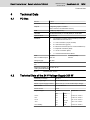
4
Technical Data
4.1
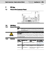
PC Box
PC box
6 slots
Processor
Celeron 440 min. 2 GHz
Chip set
Integrated graphics controller
with a maximum of 8 MB video memory
RAM
1 GByte (4 GByte max.)
Hard disk
80 GB, alternatively 2 × 80 GB (RAID) or 32 GB SSD
Optional drives
DVD burner
Interfaces
●
CDI interface (compact display interface) screen and
data interface to the VDP xx.3
●
1 × VGA connection (15-pin, HD-Sub)
●
8 × USB connection (type A)
●
2 × Ethernet connection (RJ 45, 10/100/1000 Base-T)
●
1 × keyboard connection (PS/2)
●
1 × mouse connection (PS/2)
●
1 × serial standard interface RS232
Slots
5 × PCI
1 × PCIe (4-fold)
Max. installation depth:
190 mm
150 mm
Voltage supply
24 VDC
Max. power consump‐ 200 W
tion
Degree of protection ac‐ PC box: IP 20
cording to DIN EN 60529
Fig.4-1:
4.2
Technical data, PC box
Technical Data of the 24 V Voltage Supply 200 W
Nominal input voltage:
DC 24 V
Input voltage range:
DC 19 V to DC 32 V
Period of power supply increase:
20 ms max. (0 V on the nominal input voltage)
Input current:
6.7 A for DC 24 V
Inrush current:
100 A
Output voltages:
Current
Tolerances
Min.
Max.
+3.3 V
0A
12 A
+2.93 V to +3.40 V
+5 V
1A
12 A
+4.80 V to +5.20 V
+12 V
1A
15.4 A
+11.4 V to +12.6 V
-12 V
0A
0.5 A
–11.4 V to –12.6 V
+5 V standby
0A
2A
+4.75 V to +5.25 V
20/101
Bosch Rexroth AG | Electric Drives
and Controls
Rexroth IndraControl VSB 40.3 | Project Planning Manual
Technical Data
Max. output power:
184 W
+3.3 V and +5 V: the max. output power may not
exceed 80 W.
+3.3 V, +5 V and +12 V: the max. output power
may not exceed 184 W.
Efficiency (under full load):
Fig.4-2:
> 0,78
Technical data of the 24 V power supply unit
When specifying the maximum output currents, observe that these
are the maximum currents possible from the respective output volt‐
age. However, it is not possible to draw the maximum current from
all output voltages at the same time. The max. output power must
not exceed 80 W at +3.3 V and +5 V. The max. output power may
not exceed 184 W at +3.3 V, +5 V and +12 V.
4.3
Ambient Conditions
In operation
Transport
Storage
+5 °C up to +45 °C
-20 °C up to +60 °C
-20 °C up to +60 °C
Max. temperature Temporal temperature changes
gradient
up to 3 K per minute
Temporal temperature changes
up to 3 K per minute
Temporal temperature changes
up to 3 K per minute
Humidity
Min. rel. humidity 5%
Min. rel. humidity 5%
Max. surrounding
air temperature
Min. rel. humidity 5%
Max. rel. humidity 85%
Min. absolute humidity 1
Max. rel. humidity 75%
g/m3
Min. absolute humidity 1
Max. rel. humidity 85%
g/m3
Min. absolute humidity 1 g/m3
Max. absolute humidity 25 g/m3
Max. absolute humidity 25 g/m3
Max. absolute humidity 25 g/m3
Condensation not allowed
Condensation not allowed
Condensation not allowed
Corresponds to climatic class 3K3 Corresponds to climatic class 2K2 Corresponds to climatic class 1K2
acc. to EN 60721-3-3
acc. to EN 60721-3-2
acc. to EN 60721-3-1
Air pressure
Up to 3000 m above sea level acc. Up to 3000 m above sea level acc. Up to 3000 m above sea level acc.
to EN 61131-2
to EN 61131-2
to EN 61131-2
Mechanical
strength
Max. vibration:
Max. shock
Max. shock
Frequency range: 10 up to 150 Hz 15 g 11 ms
15 g 11 ms
Excursion:
acc. to EN 60068-2-27
acc. to EN 60068-2-27
2
2
2
Overvoltage cate‐ 2
gory according to
EN 60664-1
-
-
0.075 mm for 10 to 57 Hz
Acceleration:
1g for 57 to 150 Hz
acc. to EN 60068-2-6
Degree of pollu‐
tion according to
EN 60664-1
Fig.4-3:
Ambient Conditions
Project Planning Manual | Rexroth IndraControl VSB 40.3
Electric Drives | Bosch Rexroth AG
and Controls
21/101
Technical Data
4.4
Standards
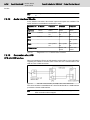
4.4.1
Used Standards
The system components of the control cabinet PCs correspond to the following
standards:
EN Standards
Standard
Meaning
EN 60,204-1
Electrical equipment of machines
EN 50,081-2
Generic standard, emitted interference (industrial envi‐
ronment)
EN 50,082-2
Generic standard, noise immunity (industrial environ‐
ment)
EN 60,742
Transformer for 24 V power supply unit, protective sepa‐
ration
EN 60,950
Overvoltage category II
EN 61,131
Requirements regarding the 24 V outputs
EN 61 131-2
Requirements on the 24 V power supply
EN 418
Machine safety, EMERGENCY STOP devices
EN 60 529
Degrees of protection (including housings and installation
compartments)
EN 60,068-2-6
Vibration test
EN 60,068-2-27
Shock test
EN 60 721-3-1 and -3
Climatic class
Fig.4-4:
4.4.2
Used standards
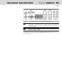
CE Marking
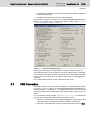
Declaration of Conformity
The electronic products described in the project planning manual comply with
the requirements and goals of the following EC guideline and with the agreed
European standards:
EMC guideline 2004/108/EC
The electronic products described in the project planning manual comply with
the requirements on the operation within the industrial environment:
Standard
Title
DIN EN
61000-6-4
Electromagnetic compatibility (EMC)
DIN EN
61000-6-2
Electromagnetic compatibility (EMC)
Edition
September
Volume: 6-4: Generic standards - Immunity for in‐ 2007
(VDE 0839-6-4) dustrial environments (IEC 61000-6-4:2006)
Volume: 6-2: Generic standards - emitted interfer‐
(VDE 0839-6-2) ence for industrial environments (IEC
61000-6-2:2005)
Fig.4-5:
Electromagnetic compatibility (EMC) standards
March 2006
22/101
Bosch Rexroth AG | Electric Drives
and Controls
Rexroth IndraControl VSB 40.3 | Project Planning Manual
Technical Data
Note for the Machine Manufacturer
The electronic products described in this project planning manual do not fall
under the machines listed in the EC guidelines. Therefore, explanations are not
required for the 89/392/EMC guideline and do not exist.
89/392/EMC, the EC guideline for machines, specifies the requirements on a
machine. In this guideline, a machine is defined as a combination of the com‐
ponents or mechanisms combined with each other. The described products
belong to the electrical equipment of a machine. Therefore, they are to be in‐
cluded in the declaration of conformity of the machine manufacturer.
The standard EN 60204-1 (safety of machinery, general requirements on the
electrical equipment of the machines) can be used for the electrical equipment
of the machines.
The CE marking is only valid for the device in its delivery status (ex
works). After modifying the device, e.g. after plugging additional
extension cards, CE compliance must be checked.
4.4.3
UL/CSA Certified
The devices of the IndraControl VSB 40.3 family are certificated according to
●
UL508 (Industrial Control Equipment) and
●
C22.2 no. 142-M1987 (CSA)
UL file no. E210730
But there can be combination or extension stages with limited or missing cer‐
tification. Thus, the registration is to be verified according to the UL marking on
the device.
The UL/CSA marking is only valid for the device in its delivery status
(ex works). After modifying the device, e.g. after plugging additional
extension cards, UL compliance must be checked.
4.5
Wear Parts
The wear parts as well as their service life are described in this section. Wear
parts are not subject to any warranty. For maitenance notes of the wear parts,
please refer to chapter 8.1 "General Information" on page 47 and for ordering
information refer to chapter 11 "Ordering Information" on page 91.
CMOS battery
The service life of a CMOS battery is at least five years. To exchange this bat‐
tery, please contact the Bosch Rexroth Service.
Hard disk
The hard disk is an electromechanical wear part that is subject to wear during
the operating time. According to the specifications of the manufacturer the
MTBF is 300,000 considering the following conditions:
Power on time
250 h/month or less than 3000 h/year
Operating hours
20 % or less of the power on time
Project Planning Manual | Rexroth IndraControl VSB 40.3
Electric Drives | Bosch Rexroth AG
and Controls
23/101
Technical Data
Operating conditions
Storage conditions
Fig.4-6:
Temperature
5 °C up to 60 °C
Rel. humidity
From 8 % to 90 %, not condens‐
ing
Height
-300 m up to 3,000 m
Accesses
30 % of the operating hours
Temperature
-40 °C up to 65 °C
Rel. humidity
From 5 % to 95 %, not condens‐
ing
Height
-300 m up to 12,000 m
Duration
< 3 months
Operating and storage conditions of the hard disk
The ambient conditions for the overall device given in chapter 4.3 "Ambient
Conditions" on page 20 have to be kept.
Solid State Drive
The SSD (Solid State Drive) shock resistance and temperature resistance is
higher compared to an ordinary hard disk. It is only subject to electrical and not
to mechanical wear.
Operating hours (power-on hours)
8760 h/year (24/7 operation)
Operating time
100% of the operating hours
Surrounding air temperature
0 °C up to 70 °C
Fig.4-7:
Service life
The MTTF is a calculated value and is 2 mill. hours if the surrounding air tem‐
perature is 25 °C.
SSD is an electronic storage medium. Defragmenting is not re‐
quired. The SSD wears faster if it is often defragmented.
Fan
Fans are mechanical wear components, whose service life is extremely tem‐
perature-dependent. For the fan integrated in the housing, the following service
life is specified by the manufacturer:
Surrounding air temperature
Service life
40 °C
60,000 hours
70 °C
30,000 hours
Fig.4-8:
4.6
Service life of the fan
Compatibility Test
All Rexroth controls and drives are developed and tested according to the latest
state-of-the-art of technology.
As it is impossible to follow the continuing development of all materials (e. g.
lubricants in machine tools) which may interact with our controls and drives, it
cannot be completely ruled out that any reactions with the materials used by
Bosch Rexroth might occur.
For this reason, before using the respective material a compatibility test has to
be carried out for new lubricants, cleaning agents etc. and our housings / our
housing materials.
24/101
Bosch Rexroth AG | Electric Drives
and Controls
Rexroth IndraControl VSB 40.3 | Project Planning Manual
Project Planning Manual | Rexroth IndraControl VSB 40.3
Electric Drives | Bosch Rexroth AG
and Controls
25/101
Dimensions, Installation and Wiring
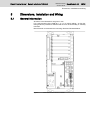
5
Dimensions, Installation and Wiring
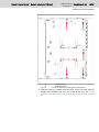
5.1
General Information
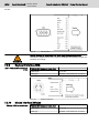
All values in the illustrations are given in mm.
For a safe mounting of the VSB 40.3 – e. g. in a control cabinet – 2x four fas‐
tening holes are provided so that the VSB 40.3 can be horizontally or vertically
mounted.
Bosch Rexroth recommends the mounting directions illustrated below.
Fig.5-1:
Front view of the VSB 40.3: vertical
26/101
Bosch Rexroth AG | Electric Drives
and Controls
Rexroth IndraControl VSB 40.3 | Project Planning Manual
Dimensions, Installation and Wiring
Fig.5-2:
Front view of the VSB 40.3: horizontal
Do observe the space required for all installation positions of connectors and
cables as well as for the opening drive. A space of at least 50 mm is required
on all sides in order to guarantee a sufficient cooling of the VSB 40.3.
Observe additional space for maintenance, if required. Example: see fig. 8-3
"Position of the hard disk and of the fastening screws (inside)" on page 50.
Observe also chapter 5.3 "Installation Notes" on page 28.
Project Planning Manual | Rexroth IndraControl VSB 40.3
Electric Drives | Bosch Rexroth AG
and Controls
27/101
Dimensions, Installation and Wiring
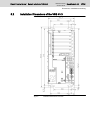
5.2
Installation Dimensions of the VSB 40.3
Fig.5-3:
Installation dimensions front view
28/101
Bosch Rexroth AG | Electric Drives
and Controls
Rexroth IndraControl VSB 40.3 | Project Planning Manual
Dimensions, Installation and Wiring
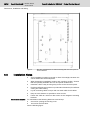
Fig.5-4:
5.3
Mounting specifications for vertical mounting with connector panel in
forward direction
Installation Notes
Maintenance distances
●
Avoid installation locations exposed to direct UV/sunlight, because this
causes additional heat development.
●
When determining installation location and mounting position, observe
that the optionally available drive can be opened unobstructed.
●
Install the VSB in a way ensuring easy access to the connector panel.
●
Provide a sufficient space of 50 mm (on all sides of the device) for sufficient
cooling and cable routing.
●
Lay all connecting cables in loops and use strain reliefs for all cables.
●
Keep as much distance as possible to noise sources.
●
Fasten the VSB 40.3 with four M5 screws at the integrated mounting
brackets.
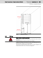
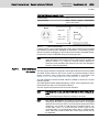
For maintenance the following distances must be kept:
●
240 mm for opening the housing cover.
●
150 mm for the DVD drive.
See the following figure:
Project Planning Manual | Rexroth IndraControl VSB 40.3
Electric Drives | Bosch Rexroth AG
and Controls
29/101
Dimensions, Installation and Wiring
Fig.5-5:
5.4
Maintenance distances
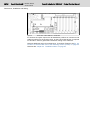
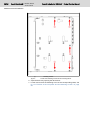
Wiring
Danger without protective separation!
DANGER
The 24 VDC input voltage must comply with the requirements of the "Protective
separation"!
Plug and unplug the connector only if there is no voltage!
Interfering AC voltage components such as the ones resulting from an uncon‐
trolled three-phase bridge circuit without smoothing and with a ripple factor (see
DIN 40110/10.75, section 1.2) of 5 % are allowed.
That results in the greatest absolute value of 30.2 V as upper voltage limit. The
lowest absolute value of 18.5 V is the lower voltage limit.
30/101
Bosch Rexroth AG | Electric Drives
and Controls
Rexroth IndraControl VSB 40.3 | Project Planning Manual
Dimensions, Installation and Wiring
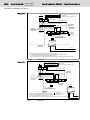
Wiring 230 V
L1
L2
L3
N
PE
PE
PE
PE
PE
PE
min. 16 mm² (green/yellow)
16 mm² (green/yellow)
6 mm² (green/yellow)
U1
V1
W1
N
leads
PE neutral point
to the housing of the control cabinet
to the device
all housing parts (functional earth)
16 mm² (green/yellow)
Fuses, better: protective motor switches
Transformer
acc. to EN60742
4 mm² (green/yellow)
Overvoltage
category II
(1)
PE
U2
N
PE
Overvoltage
category III
230V
4 mm² (green/yellow
L1.1
L2.1
L3.1
N
PE
N-conductor:
Use only with
permission of
the operator!
400V
e.g. drives
PE
N1
U2
4 mm² (green/yellow)
Terminals in
isolated
arrangement
230 V power supply
operator terminals
service plug receptacle(s)
Power unit
VAP01.1H-W23
024-010-NN
24 VDC
Overvoltage
category I
+24 V
0V
Length max. 4 m
(1) PE bars are to be installed preferably on the mounting plate.
In case of isolated PE bars, both ends must be connected to the mounting plate
by means of copper strips with a maximum length of 20 cm.
The cross-section of the copper strips has to be at least equal to that of the incoming mains cable.
Fig.5-6:
Wiring 230 V
Wiring 400 V
L1
L2
L3
N
PE
PE
PE
PE
PE
PE
min. 16 mm² (green/yellow)
16 mm² (green/yellow)
6 mm² (green/yellow)
U1
V1
W1
N
leads
PE neutral point
to the housing of the control cabinet
to the device
all housing parts (functional earth)
16 mm² (green/yellow)
Fuses, better: protective motor switches
400V
Overvoltage
category III
Transformer
acc. to EN 60742 230V
L1.1
L2.1
L3.1
N
PE
N conductor:
Use only with
permission of
the operator!
4 mm² (green/yellow)
4 mm² (green/yellow)
PE
N
U2
(1)
PE
e.g.drives
Overvoltage
category II
230 V supply
operator terminals
service plug receptacle(s)
Overvoltage
category I
(1)PE
= Terminals in
isolated arrangement
bars are to be installed preferably on the mounting plate.
In case of isolated PE bars, both ends must be connected to the mounting plate
by means of copper strips with a maximum length of 20 cm.
The cross-section of the copper strips has to be at least equal to that of the incoming mains cable.
Fig.5-7:
Wiring 400 V
L1.1
L2.1
L3.1
PE
PE
N1
U2
4 mm² (green/yellow)
Power unit
24 VDC
+24 V
0V
Project Planning Manual | Rexroth IndraControl VSB 40.3
Electric Drives | Bosch Rexroth AG
and Controls
31/101
Dimensions, Installation and Wiring
Control cabinet PC and display to
UPS
Overvoltage category I
(4)
24+24V
V
A
X1S1
6 mm² (blue)
(2)
24V OUT
24V IN
(4)
OV
UPS
(VAU 01.1 )
16 A
A
0V IN
VSB 40.3
VSP xx.3
VPB 40.3
VPP xx.3
Terminal block UK6-FSI/6
with automatic cut-out TCP 10 A
(PHOENIX CONTACT) is recommended
+
(3)
X10
X1S2
0V OUT
Terminal block UK6-FSI/6
with automatic cut-out TCP 4 A
(PHOENIX CONTACT)
FE
VDP xx.3
(1)
(5)
+
FE = functional earth
10 mm² (green/yellow)
6 mm² to be connected to FE of VDP xx.3 .
6 mm² to be connected to FE of VPB 40.3 , VPP xx.3 , VSB 40.3 , VSP xx.3 .
6 mm² to be connected to FE of the UPS (VAU 01.1 ).
PE bar
B
FE
-
(3)
X1S1
FE
-
(1) Easily removable and visible
10 mm² (green/yellow)
(2) Cable length between UPS and VPB 40.3 and VPP xx.3 max. 2 m at a minimum
cross-section of 2.5 mm².
A = Terminal block 4 mm²
B = Terminal block 10 mm²
(3) Polarity reversal of the X1S1 and X10 connectors can destroy the device,
if there is no additional external protection (fire danger). This is caused by the
simultaneous grounding of the 0 V of the device and the 0 V (PELV) (1).
(4) Cable length between +24 V power supply unit and UPS max. 2 m at a minimum
cross-section of 5 mm² (see project planning manual of the UPS VAU 01.1).
(5) Cable length between +24 V power supply unit and VDP xx.3 max. 30 m at a minimum
cross-section of 1.5 mm². An additional power supply unit is required if the length exceeds 30 m.
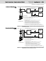
Fig.5-8:
PC (VSB 40.3, VSP xx.3, VPB 40.3, VPP xx.3) and display (VDP xx.3)
connected to an UPS
Only control cabinet PC connected
to UPS
Overvoltage category I
(4)
24+24V
V
16 A
A
A
X1S1
6 mm² (blau)
0V IN
VSB 40.3
VSP xx.3
VPB 40.3
VPP xx.3
Terminal block UK6-FSI/6
with automatic cut-out TCP 10 A
(PHOENIX CONTACT) is recommended
(2)
24V OUT
24V IN
(4)
OV
UPS
(VAU 01.1 )
+
X1S2
0V OUT
FE
VDP xx.3
FE = functional earth
10 mm² (green/yellow)
6 mm² a to be connected to FE of VDP xx.3 .
PE bar
FE
Terminal block UK6-FSI/6
with automatic cut-out TCP 4 A
(PHOENIX CONTACT) is recommended
(1)
B
(3)
X10
-
(5)
+
(3)
X1S
FE
-
6 mm² a to be connected to FE of VPB 40.3 , VPP xx.3 , VSB 40.3 , VSP xx.3 .
6 mm² a to be connected to FE of the UPS (VAU 01.1 ).
10 mm² (green/yellow)
(1) Easily removable and visible.
(2) Cable length between UPS and VPB 40.3 and VPP xx.3 max. 2 m at a minimum
cross-section of 2.5 mm².
A = terminal block 4 mm²
B = terminal block 10 mm²
(3) Polarity reversal of the X1S1 and X10 connectors can destroy the device,
if there is no additional external protection (fire danger). This is caused by the
simultaneous grounding of the device and the 0 V (PELV) (1).
(4) Cable length between +24 V power supply unit and UPS max. 2 m at a minimum
cross-section of 5 mm² (see project planning manual of the UPS VAU01.1).
(5) Cable length between +24 V power supply unit and VDP xx.3 max. 30 m at a minimum
cross-section of 1.5 mm². An additional power supply unit is required if the length exceeds 30 m.
Fig.5-9:
PC (VSB 40.3, VSP xx.3, VPB 40.3, VPP xx.3) connected to an UPS.
Display (VDP xx.3) not connected to an UPS
32/101
Bosch Rexroth AG | Electric Drives
and Controls
Rexroth IndraControl VSB 40.3 | Project Planning Manual
Project Planning Manual | Rexroth IndraControl VSB 40.3
Electric Drives | Bosch Rexroth AG
and Controls
33/101
Display and Operating Components
6
Display and Operating Components
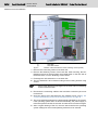
6.1
Power Button
Next to the connector panel (see fig. 7-1 "Position of the connections" on page
37), a button labeled with "PWR" is provided.
Due to the default setting of the BIOS, the control cabinet PC starts when volt‐
age is applied. If you have changed this setting in the BIOS, the control cabinet
PC can be started via the "PWR" power button.
In order that the control cabinet PC starts again when a voltage is applied,
proceed as follows:
1. Start the BIOS setup by pressing <Del> while booting.
2. Change to the "Chipset" menu.
3. Select the setting "[Power On]" in "Restore on AC Power loss" under
"South Bridge Chipset + Configuration".
6.2
Display, Monitor and Keyboard
6.2.1
Display
To display and operate the VSB 40.3 we recommend the displays VDP 16.3
and VDP 40.3, especially designed for industrial applications by Bosch
Rexroth . The displays are connected with the VSB 40.3 via the CDI interface.
The VDP operator displays are equipped with a foil keyboard AND/or with a
touch screen.
Operate the touch screen only with a touch pen or your finger.
You can also connect mouse and keyboard to these displays.
6.2.2
VGA Monitor
A standard monitor (female connector XVGA) can be connected to the VSB
40.3.
6.2.3
Selection of the Graphics Driver
When the VSB device is delivered, the settings allow to trigger a connected
monitor and a connected VDP.
Activating the VDP or an external
monitor
If the VDP connected to the CDI interface, the external monitor operated at the
VGA connection or both are addressed, can be selected as follows:
1. Select "Intel(R) Extreme Graphics" in the task bar.
Fig.6-1:
Intel® Extreme Graphics
2. Select Graphics Options ▶ Graphics Properties.
34/101
Bosch Rexroth AG | Electric Drives
and Controls
Rexroth IndraControl VSB 40.3 | Project Planning Manual
Display and Operating Components
Fig.6-2:
Graphics Properties
3. The "Digital Display and Monitor" window opens.
Fig.6-3:
"Display Devices" tab
4. If an external monitor is connected, the user can select whether only the
external monitor (selecting "Monitor"), only the screen of the connected
display (selecting "Digital Display") of both the screens (selecting "Twin"
or "Intel(R) Dual Display Clone") should be activated.
5. After confirming using "OK", another window opens in which the selection
is to be reconfirmed by pressing "OK". Otherwise, the monitor selection is
not applied.
Project Planning Manual | Rexroth IndraControl VSB 40.3
Electric Drives | Bosch Rexroth AG
and Controls
35/101
Display and Operating Components
Fig.6-4:
Confirming desktop changes
If the connected external monitor or the connected display is black,
because the corresponding display is not activated, you can select
the action using the key combinations illustrated in the following
"Hot Keys" tab.
"Monitor" corresponds to the external monitor and "Digital Dis‐
play" corresponds to the VDP display.
The key combinations can only be activated if a user is logged in!
Fig.6-5:
"Hot Keys" tab
36/101
Bosch Rexroth AG | Electric Drives
and Controls
Rexroth IndraControl VSB 40.3 | Project Planning Manual
Project Planning Manual | Rexroth IndraControl VSB 40.3
Electric Drives | Bosch Rexroth AG
and Controls
37/101
PC Box
7
PC Box
7.1
View on the Connector Panel
Fig.7-1:
7.2
Interfaces
7.2.1
General Information
Position of the connections
Malfunctions due to insufficient shielding! Use only shielded cables
and metallic or conductive connector/coupling covers with largearea shield support.
Material damages to electronics due to missing functional earth ground
connection!
CAUTION
7.2.2
Please ensure that the functional earth ground is connected, because other‐
wise the electronics can be destroyed by a potential difference between the
VDP xx.3 and the VSB 40.3 if the voltage supply is interrupted to only one device
and established again.
Overview
Labeling
of Connection type
the housing
Connector type (inte‐ Mating connector or
grated)
cable (from outside)
X10
PC supply voltage: 24 Screw terminal
VDC
XCOM
Serial
RS232
XUSB 1 to 8
8 USB interfaces
See chapter chapter
7.2 "Interfaces" on
page 37
interface: D-Sub male connec‐ D-Sub female con‐
tor, 9-pin
nector, 9-pin
USB female connec‐ USB male connector,
tor, 4-pin, type A
4-pin
38/101
Bosch Rexroth AG | Electric Drives
and Controls
Rexroth IndraControl VSB 40.3 | Project Planning Manual
PC Box
Labeling
of Connection type
the housing
XLAN1,
XLAN21)
connec‐ RJ45 female connec‐ RJ45 connector (twis‐
tor, 8-pin
ted pair, 8-wire)
Ethernet 10Base T /
100Base X / 1000
Base T
XVGA
VGA connection for VGA HD female con‐ VGA HD male con‐
external monitor
nector, 15-pin
nector,
15-pin
XKB
PS/2 keyboard
Mini-DIN PS/2 female Mini-DIN PS/2 male
connector, 6-pin
connector, 6-pin
XMS
PS/2 mouse
Mini-DIN PS/2 female Mini-DIN PS/2 male
connector, 6-pin
connector, 6-pin
XSER
CDI interface "data"
RJ45 female connec‐ RJ45 connector
tor
XVID
CDI interface "Screen" RJ45 female connec‐ RJ45 connector
tor
XAUDIO
Audio (disabled in the (see chapter 7.2.12 "Audio Interface XAu‐
BIOS by default)
dio" on page 44)
Fig.7-2:
7.2.3
2 network
tions:
Connector type (inte‐ Mating connector or
grated)
cable (from outside)
Connector types VSB 40.3
PC Voltage Supply
24 VDC voltage supply
All internally required voltages are generated from the 24 VDC supply.
Fig.7-3:
Connection terminals for the 24 VDC supply
For wiring connection terminals use copper wire only. Tighten the
screws of the screw terminals with a torque of 4 lb in (0.4 Nm).
Parameters
Value
Input voltage UN
24 VDC; (19 to 32 VDC)
Power consumption for 19 VDC
10 A max.
Fig.7-4:
1)
Technical data of the 24 VDC connection
Information about LAN assignment in Windows XP, see chapter 7.2.7 "Ethernet
Interface XLAN" on page 40.
Project Planning Manual | Rexroth IndraControl VSB 40.3
Electric Drives | Bosch Rexroth AG
and Controls
39/101
PC Box
Danger without protective separation!
The 24 VDC input voltage must comply with the requirements of the "Protective
separation"!
DANGER
Plug and unplug the connector only if there is no voltage!
Interfering AC voltage components such as the ones resulting from an uncon‐
trolled three-phase bridge circuit without smoothing and with a ripple factor (see
DIN 40110/10.75, section 1.2) of 5 % are allowed.
That results in the greatest absolute value of 30.2 V as upper voltage limit. The
lowest absolute value of 18.5 V is the lower voltage limit.
For further information please refer to chapter 5.4 "Wiring" on page 29.
7.2.4
Serial Interface XCOM
XCOM – Serial interface
A serial standard interface is provided at the XCOM connection.
D-Sub male connector, 9-pin
Type
RS232
Cable length
15 m max.
Cable type
Shielded, cross-section min. 0.14 mm2
Transmission Rate
Max. 115200 bits/s
Handshake
Hardware and software handshake (XON, XOFF)
Interrupt (IRQ):
4
I/O address
AUTO (or 3F8H)
BIOS presetting
Enabled
Fig.7-5:
7.2.5
Pin assignment COM
Settings of the Serial Interface
Control panel
For the transfer parameter settings of the serial interfaces, please refer to the
description of the installed operating system (for Windows under Start ▶ Set‐
tings ▶ Control Panel ▶ ...).
BIOS
The BIOS setting of COM (Serial Port A) is preset to AUTO (automatic param‐
eter assignment). Apply the following settings to assign the parameters directly:
40/101
Bosch Rexroth AG | Electric Drives
and Controls
Rexroth IndraControl VSB 40.3 | Project Planning Manual
PC Box
●
COM = 3F8H
Interrupt (IRQ) and I/O address have to correspond to the settings
carried out in BIOS.
7.2.6
XUSB Interfaces
XUSB 1 to 8 – serial interfaces for
printers, scanners, drives
The devices feature eight USB interfaces on the connector panel (XUSB).
These interfaces are compatible to USB 1.1 and USB 2.0.
The maximum power consumption of the connected devices must
not exceed 500 mA. If the load exceeds 500 mA, the internal current
monitoring is activated.
Fig.7-6:
7.2.7
USB interfaces
Pin
Function
1
USB power supply (max. 500 mA)
2
Data -
3
Data +
4
USB ground
Ethernet Interface XLAN
XLAN1 and XLAN2 – network con‐
nection
The control cabinet PC can be connected to an Ethernet network via the XLAN
Ethernet interface.
The LAN assignment in Windows XP to the XLAN devices at the device is preset
as follows:
Designation in Windows XP
Designation at the housing
Local Area Connection
XLAN2
Local Area Connection 2
XLAN1
Fig.7-7:
Assignment of the LAN interfaces in the operating system to the inter‐
faces at the device
RJ45, female connector, 8-pin
Type:
Ethernet 10/100/1000
Cable length:
100 m max.
Transmission rate:
10, 100 and 1000 MBit/s
Project Planning Manual | Rexroth IndraControl VSB 40.3
Electric Drives | Bosch Rexroth AG
and Controls
41/101
PC Box
Fig.7-8:
Ethernet interface XLAN
The driver configuration of the network connection can be called up in the task
bar or in the "Control Panel" with the "Network board" icon. It can be set whether
the data transmission should be carried out with 10 Mbits/s, 100 Mbits/s or
1000 MBit/s via the network.
Observe that the network board of the remote station has to be able
to process the same data transmission rate.
7.2.8
XVGA Interface
XVGA – Connection external mon‐
itor
An external monitor can be connected to the VGA connection (XVGA). The
monitor can be operated via the integrated video adapter as or parallel to a VDP
that is connected via the CDI display interface.
HD female connector, 15-pin
Cable length
1.5 m max.
Cable type
Shielded, cross-section min. 0.14 mm2
Max. resolution
2048 × 1536 pixels, 75 Hz, max. 4294 mio.
colors
42/101
Bosch Rexroth AG | Electric Drives
and Controls
Rexroth IndraControl VSB 40.3 | Project Planning Manual
PC Box
Fig.7-9:
VGA interface
Wrong settings of resolution and color may destroy the monitor!
WARNING
7.2.9
Observe the technical data of the monitor and adapt the operating system pa‐
rameters accordingly.
Keyboard Interface XKB
XKB – PS/2 mini DIN keyboard in‐
terface
PS/2 Mini DIN female connector, 6-pin
Cable length
1.5 m max.
Cable type
Shielded, cross-section min. 0.14 mm2
Fig.7-10:
7.2.10
Keyboard interface
Mouse Interface XMouse
XMouse – PS/2 mouse interface
PS/2 Mini DIN female connector, 6-pin
Cable length
1.5 m max.
Cable type
Shielded, cross-section min. 0.14 mm2
Project Planning Manual | Rexroth IndraControl VSB 40.3
Electric Drives | Bosch Rexroth AG
and Controls
43/101
PC Box
PS/2 Mini DIN female connector, 6-pin
Interrupt (IRQ):
12
BIOS presetting
PS/2 mouse support:
Mouse: Auto detect
Fig.7-11:
EnabledPS/2
Mouse interface XMS
If a PS/2 mouse is not recognized by the system, the mouse has to be activated
in the BIOS by switching from "Disabled" to "Autodetect". The operating system
will not recognize the plugging-in of an external mouse after completed startup,
because the mouse is initialized during the booting process.
The connected mouse is to be compy with the PS/2 standard. Gen‐
erally, the BIOS reserves IRQ 12 for the PS/2 mouse. If there are
address conflicts, e. g., if IRQ 12 is already used by different PC
extension cards, the IRQ of this extension card is to be changed to
another, still unassigned IRQ.
7.2.11
CDI Interface
CDI Interface
The CDI display interface is assigned to the two RJ45 female connectors XSER
and XVID. Connect either a VDP 16.3 or a VDP 40.3 operator display to these
female connectors using ready-made cables available as accessories (see
chapter 11.2.3 "Connecting Cable for the CDI Interface" on page 92).
The CDI interface includes the data interface (XSER) as well as the screen
interface (XVID).
The USB signals and the digital data (M-keys, LEDs, control signals) are trans‐
ferred to/from the VDP xx.3 via the data interface.
The DVI signals are transferred via the screen interface.
It is dangerous to plug and remove CDI cables when voltage is ap‐
plied.
The functional earth ground (FE) is always to be used.
The display identification of a VDP xx.3 is only once active after
switching on the VPB 40.3. That means that if a VDP xx.3 is plugged
and then removed or if a VDP is connected when starting the control
cabinet PC, only a VDP xx.3 with the same resolution can be con‐
nected again. Thus, it is ensured that the screen output on the
connected VDP xx.3 automatically works after a voltage break‐
down, without the need to switch the screen output to the VDP by
the keyboard.
44/101
Bosch Rexroth AG | Electric Drives
and Controls
Rexroth IndraControl VSB 40.3 | Project Planning Manual
PC Box
Use only cables listed in chapter 11.2 "Accessories" on page
91.
7.2.12
Audio Interface XAudio
At the XAudio connections also Audio inputs and outputs are available. The
Audio interfaces are disabled in the BIOS ex works.
Connector col‐
or
2-channel
4-channel
6-channel
8-channel
Light blue
Line in
Line in
Line in
Line in
Lime
Line out
Front speaker
out
Front speaker
out
Front speaker
out
Pink
Mic in
Mic in
Mic in
Mic in
Gray
-
-
-
Side speaker
out
Black
-
Rear speaker
out
Rear speaker
out
Rear speaker
out
Yellow orange
-
-
Center, sub‐
woofer
Center, sub‐
woofer
Fig.7-12:
7.2.13
Assignment of 7.1 + 2-channel audio connection
Connection of a UPS
UPS with USB Interface
When connecting an UPS to an USB interface at the VSB 40.3, the information
regarding the existence and the status of the UPS are communicated to the
VSB 40.3 via a USB connection.
Fig.7-13:
UPS with communication (via USB) to the control cabinet PC
The communication is established via a virtual COM interface. A USB interface
provides the virtual COM interface.
The USB connection XUSB2 has already been configured for the
UPS connection when shipped.
Project Planning Manual | Rexroth IndraControl VSB 40.3
Electric Drives | Bosch Rexroth AG
and Controls
45/101
PC Box
Fig.7-14:
Connecting the UPS to the XUSB2 USB connection
The driver is installed after the first connection of the UPS via the
USB cable. A virtual COMn (e.g. COM3) interface is created in the
operating system.
There is a defined assignment of the UPS to the USB interface for
firmware version 01VRS.
For further information about UPS cabling please refer to chapter 5.4 "Wir‐
ing" on page 29.
46/101
Bosch Rexroth AG | Electric Drives
and Controls
Rexroth IndraControl VSB 40.3 | Project Planning Manual
Project Planning Manual | Rexroth IndraControl VSB 40.3
Electric Drives | Bosch Rexroth AG
and Controls
47/101
Maintenance and Installation
8
Maintenance and Installation
8.1
General Information
control cabinet PCs of the VSB design are maintenance-free. Some compo‐
nents are subject to wear and must be replaced (see chapter 4.5 "Wear
Parts" on page 22).
If the screws were removed due to maintenance, they are now to
be fastened with the respective mounting torques specified in the
following table.
Threads
Mounting torques
M2.5
0.4 Nm
M3
0.7 Nm
M4
1.4 Nm
M5
2.8 Nm
Fig.8-1:
Maintenance
Mounting torques
Include the following measures in the maintenance schedule:
●
At least once a year, all plug and terminal connections of the components
are to be checked regarding proper tightness and possible damage.
Check that cables are not broken or crushed. Damaged parts must be
replaced immediately.
●
The fan is to be checked at least once a year.
Risk of injury by rotating fan impeller!
DANGER
The fan impeller is not to be touched with the hands and may not come into
contact with other objects.
●
Ensure that the VSB 40.3 is connected to a working uninterruptible power
supply unit (UPS).
Bosch Rexroth provides uninterruptible power supplies for the 24 V
supply as accessory (see chapter 11.2 "Accessories" on page
91).
8.2
CMOS Battery
The battery used for buffering the RAM, BIOS and the clock has a limited serv‐
ice life (see chapter 4.5 "Wear Parts" on page 22).
This lithium battery may not be changed by the user. The battery may only be
exchanged by the Bosch Rexroth Service (see chapter 12 "Service and Sup‐
port" on page 95) or by personnel trained and authorized by the Service.
Batteries might cause fire, explosions or chemical burn!
Do not load, remove, destroy, burn or heat batteries over 100 °C.
WARNING
Dispose old batteries immediately and properly.
Keep away from children.
48/101
Bosch Rexroth AG | Electric Drives
and Controls
Rexroth IndraControl VSB 40.3 | Project Planning Manual
Maintenance and Installation
8.3
Hard Disk
8.3.1
General Information
Loss of data!
WARNING
All required application data as well as operating system settings are to be
backed up on an external data carrier!
Damages on the VSB 40.3 due to electrostatic discharges!
WARNING
Comply with all ESD protective measures while working with modules and
components! Avoid electrostatic discharges!
To store user data and to avoid the reinstallation of the operating
system and application programs after a hard disk exchange, back‐
up the well-working hard disk at regular intervals.
The hard disk to be inserted must already be provided with an in‐
stalled operating system, if no external boot medium is connected
to the control cabinet PC! In any case, we recommend you to have
a completely installed operating system on the hard disk to shorten
the installation time!
8.3.2
Exchanging the Hard Disk of the VSB 40.3
1. All required user data as well as the operating system settings of your
system are to be stored either on an external storage medium or via the
network connection! For the back up, see also chapter 9 "Software" on
page 55.
2. Switch off the supply voltage.
3. Wait until the power supply unit switches off automatically after the UPS
operation.
4. Ensure that no voltage is in the control cabinet PC. Disconnect the PC
power supply from the X10 connection, if required, see "24 VDC voltage
supply" on page 38.
5. Remove the five marked screws on the housing side, see fig. 8-2 "Loosen
the fastening screws at the mounting frame" on page 49:
Project Planning Manual | Rexroth IndraControl VSB 40.3
Electric Drives | Bosch Rexroth AG
and Controls
49/101
Maintenance and Installation
①
②
Fig.8-2:
Housing screws
Hard disk screws
Loosen the fastening screws at the mounting frame
6. Open the device by opening the device door. One or two hard disks are
located in the middle of the inner side of the device door, see fig. 8-3
"Position of the hard disk and of the fastening screws (inside)" on page
50.
50/101
Bosch Rexroth AG | Electric Drives
and Controls
Rexroth IndraControl VSB 40.3 | Project Planning Manual
Maintenance and Installation
①
②
Fig.8-3:
Hard disk
Hard disk screws
Position of the hard disk and of the fastening screws (inside)
7. Remove the connecting cables of the hard disk.
8. Remove the fastening screws of the hard disk. After mounting, the four
fastening screws for the hard disks are located either on the rear side of
the device door or on the fastening screw holders.
9. Exchange the old hard disk for a new hard disk.
10. The new hard disk is to be fixed according to the mounting location using
screws.
Observe the different screw lengths for the outer and inner fastening
screws of the hard disk.
11. Reconnect the connecting cables to the hard disk. Connection pins must
not be bent!
12. Close the device door and fasten the five marked screws, see fig. 8-2
"Loosen the fastening screws at the mounting frame" on page 49.
13. The new hard disk parameters are automatically identified by the system.
If the operating system does not boot automatically, the power supply is
to be interrupted for at least 10 seconds. A restart is to be carried out again.
14. After a regular booting of the PC, the user data as well as the operating
system settings for the normal operating mode are to be restored.
Project Planning Manual | Rexroth IndraControl VSB 40.3
Electric Drives | Bosch Rexroth AG
and Controls
51/101
Maintenance and Installation
8.4
Extension Cards
8.4.1
General Information
PCIe slots and PCI slots are available for plugging extension cards. The max‐
imum performance for all extension cards for the devices provided with a
Celeron 440 processor is a total of 100 watt. The maximum performance for all
extension cards with an Intel® Core2TM processor is 70 watt.
Risk of damage to the control cabinet PC or to the extension cards due
to electrostatic discharges!
WARNING
Comply with all ESD protective measures while working with modules and
components! Avoid electrostatic discharges!
Risk of damage to the control cabinet PC or corruption of application
software due to the use of of non-released extension cards!
WARNING
8.4.2
Only released extension cards are to be installed. Installation is only to be car‐
ried out by authorized personnel.
Inserting Extension Card
1. All required user data as well as the operating system settings of the sys‐
tem are to be stored either on an external storage medium or via the
network connection! See also chapter 9 "Software" on page 55.
2. Switch off the supply voltage.
3. Wait until the power supply unit switches off automatically after the UPS
operation.
4. Ensure that no voltage is in the control cabinet PC. Disconnect the PC
voltage supply from the X10 connection, if required, see "24 VDC voltage
supply" on page 38.
5. Remove the five marked screws at the housing side, see fig. 8-2 "Loosen
the fastening screws at the mounting frame" on page 49.
52/101
Bosch Rexroth AG | Electric Drives
and Controls
Rexroth IndraControl VSB 40.3 | Project Planning Manual
Maintenance and Installation
①
Fig.8-4:
Housing screws
Loosen the fastening screws at the mounting frame
6. Open the device by opening the device door.
7. Loosen and remove the fastening screw of the corresponding sheet, see
fig. 8-5 "Position of the slot plates and the fastening screws" on page
53.
Project Planning Manual | Rexroth IndraControl VSB 40.3
Electric Drives | Bosch Rexroth AG
and Controls
53/101
Maintenance and Installation
Fig.8-5:
Position of the slot plates and the fastening screws
8. Insert the plug-in assembly directly. Don't use force. The connections are
to be inserted in the plug on the main board.
9. Fasten the plug-in assembly with the screw used to fix the sheet.
10. Close the device door and fasten the five marked screws, see fig. 8-2
"Loosen the fastening screws at the mounting frame" on page 49.
If the card is equipped with a Plug and Play (PnP) function, it is automatically
recognized by the operating system and integrated in the system, provided that
there are no hardware conflicts (IRQ etc.) with other extension cards or con‐
nected devices.
There can be different reasons why the functions - based on the new card - are
not available after the system reboot:
●
The card is not properly positioned in the PCI slot.
●
The driver software of the card was not installed or was installed faulty.
●
IRQ (Interrupt) conflict with other PC hardware components.
●
The software of the card was not installed.
54/101
Bosch Rexroth AG | Electric Drives
and Controls
Rexroth IndraControl VSB 40.3 | Project Planning Manual
Project Planning Manual | Rexroth IndraControl VSB 40.3
Electric Drives | Bosch Rexroth AG
and Controls
55/101
Software
9
Software
9.1
Windows XP Multi-User-Interface (MUI)
At delivery the English version of Windows XP is preinstalled on the VSB
40.3 devices. Further languages are available for the installation. They can be
installed via the "MUI Inst" desktop icon.
①
Fig.9-1:
Mulit-User-Interface-Software icon
"MUI Inst" desktop icon
The following dialog appears after calling the Windows XP MUI installation:
Fig.9-2:
"Windows XP MUI Installation" dialog
In "Step 1" choose the languages to be installed on the system by selecting the
corresponding checkbox. Choose the language to be preset during system start
by selecting the corresponding radio button.
Under "Step 2" all installation files can be removed from the hard disk to get
more free storage space on the hard disk. Select the checkbox if the installation
files are to be removed.
56/101
Bosch Rexroth AG | Electric Drives
and Controls
Rexroth IndraControl VSB 40.3 | Project Planning Manual
Software
If several languages are installed, the languages can be changed
using "Regional and Language Options" in the Windows Control
Panel.
9.2
Data backup with Acronis True Image Echo Workstation
9.2.1
Introduction
Overview
This chapter describes the execution of a data backup of the entire system at
the Rexroth PC operating devices.
The VSB 40.3 can be ordered with or without backup software. Backups can
be created manually or automatically if the device has been ordered with the
backup software. We recommend you to execute data backups cyclically to be
able to restore quickly the original state in case of failure (e.g. defective hard
disk).
This chapter describes a data backup solution that serves to backup and re‐
cover the operating system and the installed user programs (entire system) by
a backup of the partition or hard disk, but not by a "selective" backup of user
data . Acronis True Image also supports the backup of individual files and di‐
rectories.
This is a brief description based on the "Build 8163" version. The
entire documentation of the Acronis True Image Echo Workstation
Software is available at "C:\Support\Software\Acronis" or on the in‐
ternet at http://www.acronis.de/enterprise/download/docs/.
The backup software is only provided in English.
We recommend you to carry out a backup after the start since the
provided Recovery CD restores only the Windows operating sys‐
tem.
Why to Backup Data?
Definition of hardware and software
requirements
EDP systems are no static systems. Data is continuously created, modified,
moved or deleted. Components are added or removed, updates are carried out
and settings are modified. There are many reasons to backup this data and
settings:
●
Saving data in case of a hardware failure.
●
Restoring the system environment after incorrect operation.
●
Saving basic settings of a system.
●
Archiving a system status before carrying out an update.
●
Providing an identical system environment.
Rexroth Industrial PC
If the industrial PC has been ordered with data backup software, please find
the "Acronis True Image Echo Workstation" software installed in the C:\Pro‐
gramFiles\Acronis directory. If further components (e.g. Acronis True Image
Management Console) are to be installed later, this can be done by calling the
"TrueImageWorkstationEchoLicenseServer_s_en.exe" program. The license
key for a new installation is visible on the device or is contained in the license
documentation.
Backup Media
●
PC in the network (backup server)
Project Planning Manual | Rexroth IndraControl VSB 40.3
Electric Drives | Bosch Rexroth AG
and Controls
57/101
Software
●
internal or external USB CD/DVD burner
●
external USB hard disk
Network
9.2.2
●
10/100 Mbits network
●
TCP/IP network protocol
●
DHCP server in the network
System Presentation
The "Acronis True Image Echo Workstation" software tool is used for carrying
out the data backup. The software can be started via a desktop icon under
Windows or via the Recovery Manager with F11 key (see chapter 9.2.10
"Creating Bootable Rescue Media" on page 68).
Fig.9-3:
Acronis desktop icon
After the start of the program, the main program window opens (see fig. 9-4
"Acronis True Image Echo Workstation main window" on page 58). The fol‐
lowing functions are available:
●
Pick a Task
–
Backup
Backup of files, directories, individual partitions or of the entire hard
disk.
–
Recovery
Recovery of the entire hard disk, individual partitions or individual
partitions and files.
●
Manage Tasks
–
Tasks
Execution of planned tasks (e.g. automatic backup, see chapter
9.2.12 "Planning Tasks" on page 69).
–
Logs
Display of log book entries of already executed tasks.
●
or Pick a Tool
–
Explore and Validate Backup Archives
Display of contents of the backup archive, mount/unmount images
(allows access to a drive), validation of backup archives for verifying
data consistency, creation of a copy of backup archives, conversion
of a backup into a virtual disk format, e.g. VMware.
–
Manage Harddisks
Cloning a disk, adding a new disk, wizard for creating a dynamic
drive.
–
Activate Acronis Startup Recovery Manager
58/101
Bosch Rexroth AG | Electric Drives
and Controls
Rexroth IndraControl VSB 40.3 | Project Planning Manual
Software
Start the Startup Recovery Manager during the boot process of the
PC, see chapter 9.2.3 "Acronis Secure Zone und Startup Recovery
Manager" on page 59.
–
Manage System Restore
Switching on or off of Microsoft System Restore.
–
Create Bootable Rescue Media
Creating a bootable medium (CD, DVD, USB stick).
Fig.9-4:
Acronis True Image Echo Worksta‐
tion
Acronis True Image Echo Workstation main window
Acronis True Image is a program that provides backup functions for hard disks
or partitions. It creates an exact image of the hard disk or single partitions and
allows restoring all contents, including the operating systems, all programs as
well as personal data and settings.
Images can be saved on the hard disk, writeable CDs/DVDs, USB hard disks
and network resources. WindowwXP-like Wizards can be intuitively operated
and explain step by step the necessary actions.
Image files can be incrementally extended. During the recovery of hard disks
and partitions different backup states can be selected.
Archive Files
Archive files have the extension "tib". These files contain the images of the
partitions or hard disks. In addition, data of the partitions or hard disk and in‐
formation, with which the recovery is realized, are contained. An archive file can
contain images of several partitions and hard disks.
During the backup process the data can be compressed and can be splitted
into several image archive files.
Project Planning Manual | Rexroth IndraControl VSB 40.3
Electric Drives | Bosch Rexroth AG
and Controls
59/101
Software
It is not recommended to archive images directly on removable me‐
dia like e. g. CDs or DVDs, as a flow control of the data is missing
because of the direct writing on these data carriers. Furthermore,
we recommend you to divide the image archives during the creation
into the corresponding size and to transmit the files after the backup
process to the removable media and to verify them.
Images of partitions contain all files and directories, independent of their prop‐
erties (hidden, system, etc.), the Master Boot Record (MBR), the File Allocation
Table (FAT) and the Root directory.
In a partition image only the hard disk sectors containing user data are saved.
The image archives can be protected with a password.
Incremental Backup
An image archive contains one or several images. Generally, these are com‐
pressed copies of partitions or entire drives. It is not only possible, to record
several partitions or hard disks in an archive file and to restore them separately,
the data of an image archive can also be updated. To achieve this, a technology
is used, that is similar to the incremental data backup. Thereby, only the data
modified since the last image creation are saved. This process (differential
backup) saves time and memory space. Please consider that the basis of an
incremental backup is always a preceding full disk backup. Therefore, the soft‐
ware analyzes at first, if an incremental backup is possible. If a full disk backup
does not exist, it is always created at first.
Further advantage of incremental backups: The recovery of a partition from the
image archive is possible with different states generated from different image
creation times. Not only the image of the respective last backup, but also e. g.
the image created at a certain time in the past can be restored.
9.2.3
Acronis Secure Zone und Startup Recovery Manager
Acronis Secure Zone
In the case, that local partitions are damaged and e. g. cannot boot anymore,
but the physical state of the HDD is still alright, it is possible to restore images
locally from the Acronis Secure Zone.
The Acronis Secure Zone is a zone on the hard disk, that is inaccessible by
ordinary Windows applications. Image archives for quick recovery of partitions
or hard disks can be safely archived in this especially protected hard disk par‐
tition. Additionally, the Acronis Secure Zone includes parts of the Acronis
Startup Recovery Manager, with which the Acronis True Image can be activated
in error case before starting the operating system and with which a corrupted
system partition can be recovered. Thus, partitions can be recoverd, even if the
Windows operating system does not start anymore. Also the rescue media to
start Acronis True Image is not required, as the information to execute the pro‐
gram is integrated in the Acronis Startup Recovery Manager.
The Acronis Secure Zone is created as logic drive in the extended
partition. The used file system is FAT32. It cannot be accessed via
a drive letter. Furthermore, no direct access to the image archives
is stored there, except for Acronis True Image itself.
Acronis Startup Recovery Manager
The Acronis Startup Recovery Manager is a boot manager with a Linux mini
operating system, with which Acronis True Image can be started by pressing
the F11 key, independently from the installed Windows, before a possibly dam‐
aged operating system boots. The main task of the Acronis Startup Recovery
Manager is the recovery of damaged operating system partitions. Also other
partitions can be recovered or backed up. The Acronis True Image started from
Acronis Startup Recovery Manager offers all functions, that are also possible
during the start of a rescue media.
60/101
Bosch Rexroth AG | Electric Drives
and Controls
Rexroth IndraControl VSB 40.3 | Project Planning Manual
Software
The Acronis Startup Recovery Manager can be activated only to‐
gether with the Acronis Secure Zone.
Creating the Acronis Secure Zone
The Acronis Secure Zone is not implemented on Rexroth industrial PCs as
default. After a hard disk exchange a saved hard disk image is restored, it also
might be necessary to recreate the Secure Zone.
Create the Acronis Secure Zone in the main program window via "Activate Ac‐
ronis Startup Recovery Manager". After the selection a wizard guides you
through the required steps:
1.
Welcome to the Activate Acronis Startup Manager Wizard!
Wizard start window.
2.
Create Acronis Secure Zone
Selecting the partition on which Acronis Secure Zone is to be created.
Note: We recommend you not to use the operating system partition, but
for example the D:\ partition.
3.
Size
Enter the desired size of the Acronis Secure Zone via a slider or direct
input. The proposed value can be taken as the size of Acronis Secure
Zone can be changed at any time via "Manage Acronis Secure Zone" in
"Tools" (on the left of the main program window).
Note: To have enough memory space for a basic backup and supplemen‐
tary incremental backups, a size of 10 GB (min.) is recommended. The
memory space reserved for Acrons Secure Zone cannot be used for other
applications.
4.
Acronis Secure Zone Protection
A password can be entered for accessing the Acronis Secure Zone.
Caution: The password must be case sensitive!
5.
Proceed
Finishing the wizard. If Acronis Secure Zone is created, the wizard dis‐
plays a message. Press the OK button to complete the process.
After creation of the Acronis Secure Zone, the Acronis Startup Re‐
covery Manager is automatically activated. During each boot proc‐
ess before starting Windows XP a message appears for approx. 3
seconds
Starting Acronis Loader...
Press F11 for Acronis Startup Recovery Manager...
The Acronis Startup Recovery Manager can be deactivated or re‐
activated via "Activate Acronis Startup Recovery Manager" at any
time.
9.2.4
Creating Image Archives
Before the image creation it must ensured, that there is enough
space on the target data carrier to store the image archive.
Project Planning Manual | Rexroth IndraControl VSB 40.3
Electric Drives | Bosch Rexroth AG
and Controls
61/101
Software
It is only allowed to backup data, if the Windows operating system
and the machine control are running and after explicit release of the
respective control system.
Generally, we recommend you to backup Windows system parti‐
tions via the Acronis Startup Recovery Manager, if the Windows
operating system is not running.
The main programm window contains the "Backup" function. After clicking on
the icon, the wizard for image creation starts:
1. Welcome to the Create Backup Wizard!
Wizard start window.
2. Select Backup Type
Selection of the backup type. There are two checkboxes for selecting if a
full backup (individual partition, all partitions) or a partial backup (individual
directories and files) is to be executed. A note that informs about what can
be stored in the marked backup type appears in the "Description" zone.
3. Partitions Selection
Select partition(s) to be backed up. All partitions of the hard disk for se‐
lection are displayed.
Note: In this selection also the selection of the Acronis Secure Zone is
displayed. If this partition or the complete hard disk including the Acronis
Secure Zone is selected for backup, a note appears, that an image of this
zone is not recommended, as it contains itself only backed up images. If
the Acronis Secure Zone is not included in the backup, it must be newly
created on a new hard disk after the recovery of the backup.
4. Source File Exclusion
Exclusion of certain file types or directories. Certain file types or directories
can be excluded from storing in the image. After the selection of a file type
in the window further file types can be added or removed.
5. Backup Archive Location
Select storage location and file name for the image archive. A directory
on one of the partitions or of an external device (CD/DVD, USB hard disk)
must be selected. There is still the possibility to create a new directory.
Saving the image on a network drive is also possible. The file name for
the image can be freely selected. If the Acronis Secure Zone is selected
as storage location, a note is displayed under "File name" that no file name
has to be defined.
6. Select Backup Mode
Selection of the backup mode. Possible backup modes:
●
Create a new full backup archive
Creates a full image of individual files, directories, partitions or the
entire hard disk.
●
Create an incremental backup
Creates an image containing only the changes after the last full
backup or the last incremental backup.
●
Create a differential backup archive
Creates an image containing only the changes after the last full
backup.
Note: Before the first incremental backup can be performed, a full
image must exist.
62/101
Bosch Rexroth AG | Electric Drives
and Controls
Rexroth IndraControl VSB 40.3 | Project Planning Manual
Software
●
7. Choose Backup Options
Possible options are the default and the user-specific option. Via userspecific options individual options can be switched on/off or modified. The
following options are available:
●
Archive Protection
Defining a password for access to the archive.
●
Pre/Post commands
Defining commands (or batch files) to be executed before or after the
backup.
●
Database support
A lot of Window services, including mail and database servers, like
Microsoft Exchange or Microsoft SQL Server, work with many
opened files. Therefore we recommend you to stop the operation of
the processes of these services during the snaphot for the creation
of the backup archive file. This can done with this option.
●
Compression level
Four compression rates are available:
–
None (no compression)
–
Normal
–
High
–
Maximum
The higher the compression level, the smaller is the memory space
requirement for the image archive file. However, the required time to
create and restore the image archive file is higher. We recommend
you to use the "normal" compression rate.
●
Backup performance
The priority of the backup process and the write speed to the storage
medium can be modified.
●
Notifications
Allows the sending of e-mails or messages via Windows Messenger
after completion of the backup process.
●
Event tracing
This option allows the sending of the backup report to the Windows
Event Log application.
●
Archive splitting
Allows the splitting of the archive into several files. The splitting can
be done automatically or can be defined by entering a fixed size. This
is recommendable if you store an archive on your hard disk and want
to burn it to a CD-R/RW, DVD-R/RW or DVD+R/RW later on.
●
Dual destination
Allows the storage of a copy of a backup in the Acronis Secure Zone
in a selected directory.
●
Error handling
Here can be defined how errors are handled during the backup proc‐
ess.
●
Additional settings
Project Planning Manual | Rexroth IndraControl VSB 40.3
Electric Drives | Bosch Rexroth AG
and Controls
63/101
Software
Allows the automatic validation (validation of data integrity) of the
backup after completion.
8. Archive Comments
Here, you can enter a meaningful comment about the image archive file.
This comment will simplify the identification of the image archive file at a
later time.
9. Proceed
Finishing the wizard and starting the image creation.
For finishing the creation of an image archive file (=backup archive
file), we recommd you to validate it with "Validate Backup Ar‐
chive" under "Explore and Validate Backup Archives" in the main
window.
9.2.5
Validating Image Archives
Image archives serve to backup or archive data. Thus, the data integrity is the
most important property of an image archive. Therefore each image archive is
to be validated after the creation.
To do so, the Acronis True Image main program window provides the "Validate
Backup Archive" function under "Explore and Validate Backup Archives". The
only step after the start window serves to select the image archive file to be
checked. Acronis True Image automatically focuses on the file containing the
last backup. After clicking Proceed Acronis True Image starts to validate the
archive. At the end of the validation a message about the successful action is
displayed.
If Acronis True Image finds an error, the image creation should be
repeated. In this case an other data carrier is to be taken as storage
medium.
9.2.6
Update and Extend Image Archives
It is not required to create a full image during each data backup. For this, the
incremental image creation can be performed. During an incremental image
creation, only the sectors of the partitions or hard disk are saved, that have
been changed since the last complete image creation. This information is saved
as part of the image archive in a new file in the directory of the full image archive.
The name of the new file is the file name of the full image archive in conjunction
with a consecutive number (see note). Incremental image creation is only rea‐
sonable on hard disk or network drives, because using a removable media the
full backup is no longer provided when writing the incremental file.
The archives of the incremental backup are always filed in the di‐
rectory of the selected full backup. The incremental archive files are
marked with a consecutive number at the end of the file name.
Example:
Name of the full image archive: Backup_Drive_C
Name of the 1st incremental archive file: Backup_Drive_C2
Name of the 2nd incremental archive file: Backup_Drive_C3
The incremental backup of a partition is started in the main program window
with the "Backup" function. After clicking on the icon, the wizard for image cre‐
ation starts:
64/101
Bosch Rexroth AG | Electric Drives
and Controls
Rexroth IndraControl VSB 40.3 | Project Planning Manual
Software
1. Welcome to the Create Backup Wizard!
Wizard start window.
2. Select Backup Type
Selection of the backup type. There are two checkboxes for selecting if a
full backup (individual partition, all partitions) or a partial backup (individual
directories and files) is to be performed. A note that informs about what
can be stored in the marked backup type appears in the "Description"
zone.
3. Partitions Selection
Select partition(s) to be backed up. All partitions of the hard disk for se‐
lection are displayed.
Note: In this selection also the selection of the Acronis Secure Zone is
displayed. If this the Acronis Secure Zone or the full hard disk including
the Acronis Secure Zone is selected for backup, a note appears, that an
image of this zone is not recommended, as it contains itself only backed
up images.
4. Source File Exclusion
Exclusion of certain file types or directories. Certain file types or directories
can be excluded from storing in the image. After the selection of a file type
in the window further file types can be added or removed.
5. Backup Archive Location
Select the image archive file to be updated or extended.
6. Select Backup Mode
Select "Create an incremental backup".
7. If the archive defined in ⓢ is protected with a password, the Archive Pro‐
tection dialog appears for entering the password.
8. Choose Backup Options
Via "Set the options manually" different settings for the backup process
can be defined. The possible options are described in ⑦ in chapter
9.2.4 "Creating Image Archives " on page 60.
9. Archive Comments
Here, you can enter a meaningful comment about the image archive file.
This simplifies the identification of the image archive at a later time.
10. Proceed
Finishing the wizard and starting the image creation.
9.2.7
Restoring Image Archives
It might be possible to restore images because of various reasons. The most
frequent causes are hard disk defects, a virus, the recovery after a program test
or a defect of the operating system, e. g. by working with the registration editor.
The recovery of one or several partitions from an image archive is started in the
main program window via the "Recover" function.
We recommended you to restore image archives only with the
Startup Recovery Manager or the rescue media.
Windows system partitions can only be restored by the Startup Re‐
covery Manager or by the rescue media.
Project Planning Manual | Rexroth IndraControl VSB 40.3
Electric Drives | Bosch Rexroth AG
and Controls
65/101
Software
Recovery of a hard disk or partition
with the Startup Recovery Manager
For recovery of a hard disk or partition with Startup Recovery Manager do the
following:
Reboot the PC and press the F11 key as soon as the following message ap‐
pears:
Starting Acronis Loader...
Press F11 for Acronis Startup Recovery Manager...
Select the "Acronis True Image Echo Workstation (Full version)" with the key
(arrow to top) and press the enter key. Acronis True Image Echo Workstation
starts.
After clicking "Recovery", the wizard for image creation starts:
1.
Welcome to the Restore Data Wizard!
Wizard start window.
2.
Backup Archive Selection
Select the image archive to be restored.
3.
If the selected archive is password-protected, the Archive Protection dia‐
log appears for entering the password.
4.
Backup Date Selection
This dialog displays all images (including data of creation and comment)
of the archive, which was selected under ②.
Select the image to be restored.
5.
Restoration Type Selection
Recovery of a hard disk, partitions or individual files or directories can be
selected.
6.
Partition or Disk to Restore
If in step ⑤ "Restore disks or partitions" was selected, this dialog is dis‐
played. The hard disk or partition to be restored can be defined here.
7.
Restored Partition Location
Select the partition, on which the image is to be restored.
Caution: The target zone is to be carefully selected, so that the right hard
disk zone is overwritten.
8.
●
If you select a target hard disk or a target partition, the selected target
hard disk or partition is overwritten.
●
If as target sector a non-partitioned sector of the hard disk is speci‐
fied, a new partition is created.
Restored Partition Type
If the partition, containing the operating system, is restored, "Active" must
be selected. For all further partitions select "Logical".
9.
Restored Partition Size
This dialog allows the reducing of partitions to be restored.
10.
Next selection
Choose if a further partition or hard disk is to be restored. If this is not the
case, select "No I do not".
11.
Restoration Options
Here further options can be selected, for example:
●
The validation of the backup archive before recovery.
66/101
Bosch Rexroth AG | Electric Drives
and Controls
Rexroth IndraControl VSB 40.3 | Project Planning Manual
Software
12.
●
A reboot of the PC after the recovery is finished.
●
Suppressing of messages during recovery.
Proceed
Finishing the wizard and starting the restoration.
Recovery at running Windows op‐
erating system
If the partition containing the operating system is selected as target for the re‐
covery, after presssing Proceed a warning is displayed that a reboot is required.
If the message is confirmed with "Reboot", there is a reboot with subsequent
start of the Startup Recovery Manager and start of the recovery. If the message
is confirmed with "Cancel", the wizard is finished.
After restoring all partitions on a new hard disk, it may be necessary
to reactivate the Startup Recovery Manager (see chapter 9.2.3
"Acronis Secure Zone und Startup Recovery Manager" on page
59).
9.2.8
Exploring Image Archives
Acronis True Image offers the possibility to explore image archives and to open
or copy selected files from the archive. Acronis True Image uses Windows Ex‐
plorer.
The function for exploring an image file can be found in the main program win‐
dow under "Explore and Validate Backup Archives". After clicking on this icon
a selection of different function is displayed. Click "Explore Backup Archives".
In the next window the archive to be explored must be selected.
Fig.9-5:
Dialog for selecting the archive to be explored
Then the selected archive and all corresponding archives (incremental and dif‐
ferential backups) are displayed.
Project Planning Manual | Rexroth IndraControl VSB 40.3
Electric Drives | Bosch Rexroth AG
and Controls
67/101
Software
In order to explore an incremental backup the following backups
must be available: all before created incremental backups and the
full backup, which served as basis. Even if only one part of the
backup is missing, the exploration cannot be performed. In order to
explore a differential backup, the full backup, which served as basis,
must be available.
By double-clicking the archive to be opened is selected. The partition from
which the archive contains data and the creation date are displayed.
Fig.9-6:
Explorer display
After double-clicking on the drive icon all directories contained in the archive
are displayed. Directories can be opened and explored and data can be copied
from the directories, if necessary.
If an image archive consists of several partial archives, they must
be available as a whole to include the contained images. Therefore,
it is not possible to integrate images distributed on CDs/DVDs. If
this should be necessary, all partial archives must be copied in a
common directory on the hard disk.
9.2.9
Removing Image Archives
The function for removing image files is in "Explore Backup Archives". This is
a subfunction of "Explore and Validate Backup Archives". After clicking "Explore
Backup Archives" a window opens for selecting the archive to be removed.
68/101
Bosch Rexroth AG | Electric Drives
and Controls
Rexroth IndraControl VSB 40.3 | Project Planning Manual
Software
Fig.9-7:
Dialog for removing an archive
The marked archive can be deleted by using the
icon (above the directory
tree) or via the context-sensitive menu (right mouse-click). There is an addi‐
tional request if the file is to be deleted.
Also several archives can be marked and deleted at the same time.
9.2.10
Creating Bootable Rescue Media
In case of irreparable hard disks or after the installation of a new hard disk, the
computer can be started with Acronis True Image via a bootable rescue media
on an external data carrier. The bootable rescue media can be created on the
following data carriers:
●
CD or DVD
An installed or external USB-CD/DVD burner required for the creation.
Note: If you want to create a DVD as bootable media, use a DVD+R, as
problems may occur if a DVD-R is used. We recommend you to test the
functionality of the created bootable media in any case.
●
USB stick
For the creation a USB stick with a minimum capacity of 64 MB is required.
The creation of the bootable rescue media is started in the main program win‐
dow via the "Create Bootable Rescue Media" function. The procedure de‐
scribes the creation of a bootable USB stick that automatically starts the Acronis
True Image Software.
After clicking on the icon, the wizard for the creation of bootable rescue media
starts.
1. Welcome to Acronis Media Builder
Wizard start window.
Project Planning Manual | Rexroth IndraControl VSB 40.3
Electric Drives | Bosch Rexroth AG
and Controls
69/101
Software
2. Rescue Media Contents Selection
"Acronis True Image Echo Workstation (Full version)" is to be selected.
This version contains the drivers required for booting USB media.
3. Bootable Media Selection
Select the USB stick from the list. The stick is displayed as "Removable
Drive" [e.g. Removable Disk (E:)].
4. Proceed
Finishing the wizard and starting the creation of a bootable USB stick.
9.2.11
Network Support
Windows software
Bootable rescue media, Startup
Recovery Manager
No settings are required for the Windows software. The available Windows
network is used.
Network with DHCP server
In networks with DHCP server it is not necessary to make settings neither in
the bootable rescue media nor after the start of Acronis True Image via the
Startup Recovery Manager.
Network without DHCP Server
In networks without DHCP server it is not necessary to enter data manually
after the start of the bootable rescue media or after the start of Acronis True
Image via the Startup Recovery Manager. Via Extras ▶ Options the network
adapter (eth0) can be configured. At least the IP address, the subnet mask and
the default gateway are to be entered.
Network adapter
Display of the network adapter
Hardware address
Display of the MAC address
DHCP
Display if used/not used
IP address
Entry of the IP address
Subnet mask
Entry of the subnet mask
DNS suffix
Optional
Default gateway
Entry of the IP address of the default gate‐
way
DNS server
Optional
WNS server
Optional
Fig.9-8:
Manual network configuration of the rescue media
If the network settings are manually entered, after double-clicking "Computers
near me" partially no network resources are indicated. Here the UNC path name
must be entered in the file name box (e. g. "\\server\Enable\" or "\\<ip_address>
\enable\"). When accessing another computer in the network the user name
and the password are requested. To log in a Windows domain, place the name
of the domain followed by a backslash before the user name (e. g."domain
\user").
9.2.12
Planning Tasks
To keep the backups automatically as up-to-date as possible, tasks can be
created (time-controlled backup orders).
We recommend you to determine, that such tasks are executed at
times, at which the control systems are not in productive operation.
70/101
Bosch Rexroth AG | Electric Drives
and Controls
Rexroth IndraControl VSB 40.3 | Project Planning Manual
Software
Tasks can only be created in the main program window under Windows. The
procedure is nearly the same as for "Create image archives" (see chapter
9.2.4 "Creating Image Archives " on page 60) extended by the time settings.
For creating a Backup task: Click on the "Tasks" function in the main program
window.
1. Scheduled Tasks
During the first calling this window is empty. The tasks you have created
are listed there. This enables you to select and to edit (modify) already
created tasks as well as to change the task name. By enabling the "Cre‐
ate" icon a new task is created. The wizard for creating a task is started.
2. Welcome to the Schedule Task Wizard!
Wizard start window.
3. Task Type Selection
Select the "Back up" type for a backup task.
4. Select Backup Type
Select "My Computer" as backup type.
5. Partitions Selection
Select the partition to be saved.
6. Source File Exclusion
Exclusion of certain file types or directories. Certain file types or directories
can be excluded from storing in the image. After the selection of a file type
in the window further file types can be added or removed.
7. Backup Archive Location
Select storage location and file name for the image archive. A directory
on one of the partitions can be selected. There is still the possibility to
create a new directory. The storing of an image on a network drive or on
an external media (USB hard disk, internal or external CD or DVD burner)
is possible as well. The file name for the image can be freely selected. If
the Acronis Secure Zone is selected as storage location, a note is dis‐
played under "File name" that no file name is to be defined.
8. Select Backup Mode
Selection of the backup mode. Possible backup modes:
●
Create a new full backup archive
Creates a new full image of individual files, directories, partitions or
of the entire hard disk.
●
Create an incremental backup
Creates an image containing only the changes after the last full
backup or the last incremental backup.
●
Create a differential backup archive
Creates an image containing only the changes after the last full
backup.
Note: Before the first incremental or differential backup can be per‐
formed, a full image must exist.
●
Choose Backup Options
Possible options are the default and the user-specific option. Via
user-specific options individual options can be switched on/off or
modified. For automatic backup tasks "Set the options manually" is
to be selected in any case; and under "Additional Settings" "Validate
Project Planning Manual | Rexroth IndraControl VSB 40.3
Electric Drives | Bosch Rexroth AG
and Controls
71/101
Software
backup archive upon its creation completion" is to be marked to
switch on the validation of the created archive.
The possible options are described in ⑦ in chapter 9.2.4 "Creating
Image Archives " on page 60.
9. Archive Comments
Here, a meaningful comment about the image archive file can be entered.
This comment simplifies the identification of the image archive at a later
time.
10. Task Running Scheduling
Here the execution time of the task is displayed. In the example Daily is
selected.
11. Daily Execution of Task
Possible times are:
●
Start time
Starting time of the task is displayed.
●
Every day
●
Weekdays
The task is executed every weekday.
The task is executed only at weekdays.
●
Every
Execution in certain day intervals.
●
Repeat task every
Multiple daily execution of a task.
12. User Information
Enter and confirm your user name and login keyword.
Note: If no login keyword is entered, the task possibly cannot be executed.
13. Finish
Finishing the wizard and saving the task.
9.3
Software for UPS Monitoring
9.3.1
General Information
This UPS NT software controls and monitors the external uninterrupted power
supply for the panel PC and the control cabinet PC.
The communication between the program and the UPS is performed via a vir‐
tual serial interface via an USB port (default port is XUSB2).
The program runs as Windows service. It is started automatically during system
start-up and can be finished or deactivated only by an authorized user.
The UPS logic is designed for a safe shutdown of all application
programs as well as of the operating system. It is not designed to
maintain the operation in case of a longer voltage breakdown!
72/101
Bosch Rexroth AG | Electric Drives
and Controls
Rexroth IndraControl VSB 40.3 | Project Planning Manual
Software
Uncontrolled machine movements or data loss when the batteries are
defective!
DANGER
If no batteries are available or if the batteries are defective or discharged, the
system RESET is executed after a voltage breakdown, without prior notice!
This could cause uncontrolled machine movements or data loss.
9.3.2
Configuration
Calling the configuration software is carried out in the Windows XP Control
Panel by selecting the "UPS NT Control " icon .
①
Fig.9-9:
UPS NT control software icon
UPS program icon in the Windows XP Control Panel
The dialog shown in fig. 9-10 "Configuration dialog of the UPS NT software" on
page 73 is used for specifying the starting behavior and the runtime behavior
of the UPS NT software. The individual values of the configuration are saved
in the registry.
A stop and a subsequent restart of the service with modified parameters is
performed after pressing "OK".
The UPS NT Control always runs as a Windows service. Changing
the user does not influence this behavior. The user cannot end the
program without administrator rights or cannot stop the monitoring.
The following dialog appears after starting the program:
Project Planning Manual | Rexroth IndraControl VSB 40.3
Electric Drives | Bosch Rexroth AG
and Controls
73/101
Software
Fig.9-10:
Configuration dialog of the UPS NT software
Enable VPx Simple Mode
VPx.3 devices can be operated in a "simple UPS mode" without communication
interface. During simple UPS operation the UPS receives only the command
for switching off the control. Further functions are not available in this mode and
therefore they are hidden in this dialog.
Com Port
With "Select COM Port" the (virtual) serial communication interface to be con‐
nected to the UPS can be selected. The delivery setting is COM3. This setting
corresponds to the USB port XUSB2.
In new systems the UPS can be connected to any interface as the
software automatically identifies this interface. There is a defined
assignment of the UPS to the USB interface for firmware version
01VRS.
Advanced Controls
●
Shutdown Delay Time
With "Shutdown Delay Time" the delay time for the shutdown is defined.
During this period of time the user can backup his data. If the data is not
saved, the applications end after the specified time without any confirma‐
tion dialog!
●
Enable Startup Accu Test
If "Enable Startup Accu Test" is selected, the UPS battery is tested during
each system restart. If an error occurs during the test, a corresponding
message is displayed.
●
Disable UPS
If "Disable UPS" is selected, the UPS function is switched off. Only rea‐
sonable for testing and installation purposes.
●
Default
74/101
Bosch Rexroth AG | Electric Drives
and Controls
Rexroth IndraControl VSB 40.3 | Project Planning Manual
Software
Default values of the dialog elements can be preset by using the "De‐
fault" button. Default values are:
Command
–
Shutdown Delay Time: 30 seconds
–
Enable Startup Accu Test: active
–
Disable UPS: inactive
In the "Command" group an executable program (*.exe; *.bat) can be entered
and activated that should be started and executed after the initialization of the
shutdown. This is to be used if applications that do not react on messages
received from the complete system are to be stopped in order to avoid data
loss.
Generally, the respective clearing and terminating programs are entered and
activated. If several programs have to be executed or if the programs have
transfer parameters, they have to be combined and entered in a batchfile.
The entry must not contain any request parameters and the pro‐
gram must not initialize any shutdown!
●
Disable Sending QueryEndSession
The "QueryEndSession" message is sent by the operating system to in‐
form about the shut-down of the system. This "Disable Sending Quer‐
yEndSession" setting impedes the sending of the system message
QueryEndSession to the whole system after a voltage breakdown. This
setting can only be activated if the "Execute Command File" checkboxes
are selected. This can be necessary if a certain sequence is to be followed
after ending the applications.
It is absolutely required to enter the responsible application as program to
be executed. The application is also responsible for sending the "Quer‐
yEndSession" message to the system!
Info
●
Shutdown Count
The given value indicates the number of shut-downs of the system caused
by the UPS function. A battery change is recommended after 3000 forced
shut-downs.
Remarks
●
General
All important events are saved in the Windows Event Viewer.
●
Battery Test
The battery test is started by pressing the "Test Battery" button. If the
battery test fails, the LED next to the "Test Battery" button switches from
green to red.
●
Disable UPS
If this checkbox is enabled in the normal operating mode and if there is a
voltage breakdown, a proper system shutdown is no longer possible!
The "Disable UPS" function is only to be used during the commissioning
of the system or during the installation of the software. Do observe that for
normal operation "Disable UPS" is unselected!
9.3.3
Installation Notes
The UPS program consists of 3 parts:
1. The control program: ups_nt.cpl
2. The actual service program: ups_nt.exe
3. The help file: ups-nt.hlp
Project Planning Manual | Rexroth IndraControl VSB 40.3
Electric Drives | Bosch Rexroth AG
and Controls
75/101
Software
All files are to be located in the $SystemRoot$\System32 directory. After calling
the Control Panel, the "UPS NT Control" icon appears (see fig. 9-9 "UPS pro‐
gram icon in the Windows XP Control Panel" on page 72).
The settings for the service can be set here.
The service can be stopped or exited only by using the Service Manager in the
Computer Management (Services). The Service Manager can be accessed for
example under Control Panel ▶ Administrative Tools ▶ Services.
Fig.9-11:
"Service Manager" in the Computer Management
Then the marked entry "UPS NT Service" can, depending on the state, be star‐
ted, stopped or exited via the context menu entries "Start", "Stop" or "Exit".
Administrator rights are required!
9.4
Maintenance Software
9.4.1
General Information
For all VSB 40.3 devices, the maintenance software "IPCMnt.exe" is installed
by default. With this software different information about the device can be ob‐
tained or settings and tests can be carried out.
Call the software via Start ▶ ProgramFiles ▶ Bosch Rexroth ▶ IPCMnt.exe.
The maintenance software contains the following tabs:
●
"Touch", touch screen calibration, see chapter 9.4.2 "Touch" on page
76.
●
"el. Type Plate" electronic type plate, see chapter 9.4.3 "El. Type Plate"
on page 77.
●
"SMART" information about the hard disk, see chapter 9.4.4 "SMART" on
page 77.
●
"HW Monitor" HW information, see chapter 9.4.5 "HW Monitor" on page
78.
●
"About" device informationen, see chapter 9.4.6 "About" on page 79.
76/101
Bosch Rexroth AG | Electric Drives
and Controls
Rexroth IndraControl VSB 40.3 | Project Planning Manual
Software
9.4.2
Touch
For touch operations with devices provided with a touch screen, the following
preparatory measures can be executed:
●
Touch screen calibration (Calibrate)
●
Testing the calibration (Test)
●
Behavior of the right mouse button
Fig.9-12:
Touch screen settings dialog
Calibrate
After the activation of the "Calibrate" button 5 markings (red crosses) are sub‐
sequently displayed. By pressing the respective position, the data required for
the calibration is collected and after pressing the 5th cross for calibration, the
position is transferred to the touch controller. An "OK" button appears for con‐
firming the successful calibration.
Test
Use the "Test" button for generating a test image with different markings for
testing the precision of the current calibration.
Right Mouse Button ...
Use the "Simulate Right Mouse Button" buttons for testing the simulation be‐
havior of the right mouse button.
The following options are available:
●
Right Mouse Button Once
After pressing the "Right Mouse Button Once" button the next "Touch
click" is interpreted as right mouse button.
●
Right Mouse Button ON
After pressing the "Right Mouse Button ON" button the next "Touch
clicks" are interpreted as right mouse button. This mode is finished by
touch double-clicking into the active dialog window.
●
Right Mouse Button OFF
The "Right Mouse Button OFF" button can also be used for exiting the
"Right Mouse Button ON" mode. However, this is only possible with an
externally connected USB mouse.
Project Planning Manual | Rexroth IndraControl VSB 40.3
Electric Drives | Bosch Rexroth AG
and Controls
77/101
Software
For devices provided with a touch screen, a software is preinstalled
for permanent availability of this function (see chapter 9.5 "Simu‐
lation of the Right Mouse Button" on page 79).
Set Sensitivity
9.4.3
Use the "Set Sensitivity" slider for setting the sensitivity with which the mouse‐
pointer follows the movement. Click "Apply" for applying the settings.
El. Type Plate
The "El. Type Plate" dialog gives information about the "electronic type plate",
of the basic devices (local) and of the displays connected to the basic operating
devices (remote). Use the "Reread" button for displaying current data.
The following information can be shown.
●
Material text
Material designation of the device
●
Material
●
Index
Parts number
Output index of the device
●
Serial no.
Serial number of the device
●
Power On Hours
Display of the operating hours up to now
Fig.9-13:
9.4.4
Display of the data of the electronic type plate
SMART
This dialog shows the SMART (Self-Monitoring, Analysis and Reporting Tech‐
nology) information about the integrated hard disk or the solid state drive (SSD).
The IPC service program evaluates the SMART parameters cyclically, see
chapter 9.6 "IPC Service Program" on page 80.
78/101
Bosch Rexroth AG | Electric Drives
and Controls
Rexroth IndraControl VSB 40.3 | Project Planning Manual
Software
Fig.9-14:
SMART information about the integrated hard disk
If the system is configured as RAID system, no information is avail‐
able!
9.4.5
HW Monitor
In the "HW Monitor" dialog the current values of different operating parameters
can be displayed. After pressing the "Start" button, the values available are
shown. Use the "Refresh Interval[s]" slider for setting the interval for renewing
data from one to ten seconds. When pressing the "Stop" button, the currently
determined values are "frozen" and the refresh is stopped.
The following information can be shown (if available):
●
CPU Temp. [C]
CPU temperature Celsius
●
CMOS Bat. [V]
Voltage of the CMOS battery (button cell) in [V]
●
CPU Fan [1/min]
Revolutions of the CPU fan in r/min
●
Case Fan [1/min]
Revolutions of the housing fan in r/min
Project Planning Manual | Rexroth IndraControl VSB 40.3
Electric Drives | Bosch Rexroth AG
and Controls
79/101
Software
Fig.9-15:
9.4.6
Display of operating parameters
About
This display provides the following information (if available):
●
Exe Info
Current software version of the program
●
Board Info
Integrated motherboard type
●
Keyboard Controller Info
Information about the keyboard controller
Fig.9-16:
Information about the program version, motherboard and keyboard con‐
troller
9.5
Simulation of the Right Mouse Button
9.5.1
General Information
This software is used for simulating a click with the right mouse button. This is
always required when context-sensitive commands are to be executed in the
dialog. For devices with touch screen the software is started automatically, the
program icon is in the taskbar. If the program does not start automatically, it
can be started via Start ▶ ProgramFiles ▶ Bosch Rexroth ▶ MgMsBut.
Fig.9-17:
Icon of the right mouse button simulation
80/101
Bosch Rexroth AG | Electric Drives
and Controls
Rexroth IndraControl VSB 40.3 | Project Planning Manual
Software
When using this function, the task bar is to be fixed via the contextsensitive menu.
9.5.2
Function
Basic function
By clicking the icon in the taskbar, the functionality is switched so that the next
click on a dialog element is interpreted as a click with the right mouse button.
This is indicated by an icon change from
to
in the taskbar.
After clicking, the display and the clicking interpretation change back to the
normal function
Extended function
.
The following context-sensitive menu appears if you click again on the icon
which causes the switching to the "right mouse button":
Fig.9-18:
Context-sensitive menu
The following functions can be selected:
●
Right Mouse Button Once
As described in the basic function
●
Right Mouse Button On
All clicks are interpreted as clicks using the "right" mouse button. This
function can be exited by double-clicking on the icon in the taskbar. The
current function (left or right mouse button active) is represented by the
respective icon.
●
Right Mouse Button Off
It is used to help only and can only be achieved with a second mouse (e.g.
USB device) if the "Right Mouse Button On" function is activated.
●
Exit
Finishs the program
9.6
IPC Service Program
The "IPCSvc" program serves for permanent monitoring of different operating
parameters of the following devices:
●
VPP xx.3
●
VPB xx.3
●
VSP xx.3
●
VSB xx.3
The following operating parameters can be cyclically monitored:
1. State of the hard disk based on the evaluation of SMART parameters or
state of the RAID system1)
2. Voltage monitoring of board voltage and CMOS battery.
1)
Depending on structure and configuration of the system.
Project Planning Manual | Rexroth IndraControl VSB 40.3
Electric Drives | Bosch Rexroth AG
and Controls
81/101
Software
3. Temperature monitoring of the housing temperature, system temperature
and CPU temperature.
4. Standstill monitoring of the CPU fan and housing fan.
The "IPCSvc" program is located in the "C:\Support\IPCMaintenance\SetupIPCSvc.exe" directory. After starting the following dialog opens (fig. 9-19
"IPCSvc configuration dialog" on page 81):
Fig.9-19:
IPCSvc configuration dialog
Each group of the dialog is responsible for a certain hardware monitoring.
If a monitored event occurs, the reaction set under "Select Action" is executed.
A message is preset, which is valid for the whole system, that displays the result
for the user in a message box. In addition, the system can be triggered for
shutdown.
In the "Select Test Intervall" zone the interval for tests is set.
9.7
USB Connection
The USB connection at the front can be disabled or enabled while the system
is booting. To do so, call the "C:\Support\IPCMaintenance\VxPUSBCtrl.exe"
program with the on (enabled) or off (disabled) parameters in the command
line. This setting is only enabled during the runtime of the system and is not
stored.
For a permanent setting start the VxPUSBCtrl.exe on|off command line
program while starting the system with the autostart function:
1. Open the "C:\Documents and settings\[USER]\Start menu\Program files
\Autostart" directory (replace the value for "USER" respectively).
2. Open the context-sensitive menu by right mouse-click and choose New.
82/101
Bosch Rexroth AG | Electric Drives
and Controls
Rexroth IndraControl VSB 40.3 | Project Planning Manual
Software
This program enables or disables only the USB interface on the
front panel.
9.8
Autologin
If "mkautolg.vbs" (in the C:\Support\IPCMaintenance\ directory) is called, the
user "Rexroth" is entered as Autologin with his password. Please observe that
the user "Rexroth" has administrator rights.
9.9
Analog VGA Monitor
Calling "InstallVSAnalogMonSupport.cmd" on VS devices allows the connec‐
tion of an analog monitor to the VGA interface of the basis device at any time
and the immediate display of the screen contents.
9.10
M-Key-UpperClassFilter
9.10.1
General Information
From firmware version 02VRS and higher, the M-Key-UpperClassFilter driver
is installed and active ex works. The M-Key-UpperClassFilter driver is used for
maintaining the downward compatibility of the M-Key-Code when existing soft‐
ware products are used on devices of the Vxx.3 generation. The incoming
keyboard data stream is analyzed and as soon as a M-key-code (F13-F24,...)
is detected, the corresponding Ctrl-LRShift-Alt-<n> code is inserted in the data
stream. This is done in the kernel level of the operating system.
If a USB special keyboard is used, it may be required to deactivate
the M-Key-UpperClassFilter, see chapter 9.10 "M-Key-Upper‐
ClassFilter" on page 82.
9.10.2
Activating and Deactivating the M-Key-UpperClassFilter
For activating and deactivating use the batch files mkeyfilter-activate.cmd and mkeyfilter-deactivate.cmd. After the execution of the
batch files the system restarts. The batch files are in the Support ▶ MKey-Filter
Driver directory.
9.11
RAID
9.11.1
General Information
The RAID system can be used either for better data security or for fast access.
RAID means "Redundant Array Of Independent Disks".
If the VSx.3 device was ordered as RAID1 system, no further settings are to be
made in the BIOS.
The values in the "Default settings" of the BIOS refer to a VSx.3 device with
one hard disk (HDD or SSD). If the "Default settings" are loaded at an existing
RAID1 system, the RAID1 system can be recovered with the following meas‐
ures.
9.11.2
Installing RAID1 System in the BIOS
To install a RAID1 system in a VSx.3 device, the following BIOS entries are
required:
1. Start the BIOS during booting with the <Del> key.
Project Planning Manual | Rexroth IndraControl VSB 40.3
Electric Drives | Bosch Rexroth AG
and Controls
83/101
Software
2. Select the "Advanced" dialog in the BIOS.
3. Select under "ATA/IDE Configuration" the "Enhanced" entry, see fig.
9-20 "Configure ATA/IDE as RAID" on page 83
Fig.9-20:
Configure ATA/IDE as RAID
4. Select under "Configure SATA as" the "RAID" entry.
5. Select the "Boot" dialog in the BIOS.
6. Select under "Boot Prority Selection" the "Device Based" value, see fig.
9-21 "Select the boot priority" on page 83.
Fig.9-21:
Select the boot priority
7. Exit and save the settings by pressing F10.
8. During subsequent booting the following is displayed, see fig. 9-22 "Dis‐
play of the boot process after RAID configuration" on page 84.
84/101
Bosch Rexroth AG | Electric Drives
and Controls
Rexroth IndraControl VSB 40.3 | Project Planning Manual
Software
Fig.9-22:
Display of the boot process after RAID configuration
The assignment of hard disks to "Port 0" and "Port 1" is defined via the
connections, see fig. 9-23 "Position of the hard disk and assignment to the
ports" on page 84.
Port 1
Port 0
1
①
Fig.9-23:
Hard disks
Position of the hard disk and assignment to the ports
9. Press <CTRL+l> to call the RAID configuration dialog, see fig. 9-24 "RAID
configuration dialog in the BIOS" on page 85.
Project Planning Manual | Rexroth IndraControl VSB 40.3
Electric Drives | Bosch Rexroth AG
and Controls
85/101
Software
Fig.9-24:
RAID configuration dialog in the BIOS
The welcome page of the configuration dialog displays possible menu op‐
tions in the top part. The bottom part displays the current RAID configu‐
ration of the hard disks.
10. Select <1> "Create RAID Volume".
11. Define the parameters for RAID operation in the following dialog, see fig.
9-25 "Parameters for RAID operation" on page 85.
Fig.9-25:
Parameters for RAID operation
Select under "RAID Level" the "RAID1(Mirror)" value if a better data se‐
curity should be reached by data mirroring. The data mirroring causes that,
in case of a hard disk failure, there is no data loss and the system still can
be booted. The mirroring causes that the capacity of the entire hard disk
is halved.
12. Confirm the entries with <Enter>. The following dialog displays an over‐
view of your setting, see fig. 9-26 "Overview RAID configuration" on page
86.
86/101
Bosch Rexroth AG | Electric Drives
and Controls
Rexroth IndraControl VSB 40.3 | Project Planning Manual
Software
Fig.9-26:
Overview RAID configuration
Save and exit the dialog with "Exit".
If a hard disk fails, the software outputs "Degrated" as status message of the
RAID system during booting. In the following example (fig. 9-27 "Hard disk fail‐
ure of the RAID system" on page 86) the right hard disk is failed at Port 1:
Fig.9-27:
9.11.3
Hard disk failure of the RAID system
RAID System under Windows
RAID system in the device manag‐
er
A RAID system that was installed in the BIOS can be displayed in the device
manager under Windows. To do so, call the device manager (Start ▶ Set‐
tings ▶ Control Panel ▶ Administrative Tools ▶ Computer Manage‐
ment ▶ System Tools ▶ Device Manager).
"SCSI and RAID controllers" contains the "Intel(R) 82801 GHM SATA RAID
Controller" entry, see fig. 9-28 "RAID controller in the device manager" on page
87.
Project Planning Manual | Rexroth IndraControl VSB 40.3
Electric Drives | Bosch Rexroth AG
and Controls
87/101
Software
Fig.9-28:
Display status of the RAID system
RAID controller in the device manager
The status of the RAID system can be displayed with the "Intel Matrix Storage
Console". The program is not installed ex works. The installation program
"iata76_enu.exe" is filed in the "C:\Support\Software\RAID" directory. Start the
installation program and follow the instructions.
After the installation the "Intel Matrix Storage Console" is available at
Start ▶ Programs ▶ Intel(R) Storage Manager, see fig. 9-29 "Path "Intel Matrix
Storage Console"" on page 87.
Fig.9-29:
Path "Intel Matrix Storage Console"
After starting the program, it opens in the default mode, see fig. 9-30 "View of
"Intel Matrix Storage Console" in the "Basic Mode"" on page 88.
88/101
Bosch Rexroth AG | Electric Drives
and Controls
Rexroth IndraControl VSB 40.3 | Project Planning Manual
Software
Fig.9-30:
View of "Intel Matrix Storage Console" in the "Basic Mode"
You can switch from the View menu into the extended mode, see fig. 9-31
"View of "Intel Matrix Storage Console" in the "Advanced Mode"" on page
88.
Fig.9-31:
View of "Intel Matrix Storage Console" in the "Advanced Mode"
In case of hard disk failure the software indicates the defective hard disk. In the
following example (fig. 9-32 "View of "Intel Matrix Storage Console" in case of
defective hard disk" on page 88) the hard disk is failed at Port 1: This is the
right disk on the carrier plate of the hard disk.
①
Fig.9-32:
Failed hard disk at Port 1
View of "Intel Matrix Storage Console" in case of defective hard disk
Position of the hard disks, see fig. 9-23 "Position of the hard disk and assign‐
ment to the ports" on page 84.
Project Planning Manual | Rexroth IndraControl VSB 40.3
Electric Drives | Bosch Rexroth AG
and Controls
89/101
Environmental Protection and Disposal
10
Environmental Protection and Disposal
10.1
Environmental Protection
Production Processes
The products are made with energy- and resource-optimized production pro‐
cesses which allow re-using and recycling the resulting waste. We regularly try
to replace pollutant-loaded raw materials and supplies by more environmentfriendly alternatives.
Prohibited Substances
We guarantee that our products include no substances according to the chem‐
icals-ban-decree. We furthermore declare that our products are free of mercury,
asbestos, PCB and chlorinated hydrocarbons.
No Release of Hazardous Substan‐
ces
Our products do not contain any hazardous substances which may be released
in the case of appropriate use. Normally, our products will not have any negativ
influences on the environment.
Significant Components
Basically, our products contain the following components:
Electronic devices
∙ Steel
∙ Aluminum
∙ Copper
∙ Synthetic materials
∙ Electronic components and modules
10.2
Motors
∙ Steel
∙ Aluminum
∙ Copper
∙ Brass
∙ Magnetic materials
∙ Electronic components and modules
Disposal
Return of Products
Our products can be returned to our premises free of charge for disposal. It is
a precondition, however, that the products are free of oil, grease or other dirt.
Furthermore, the products returned for disposal must not contain any undue
foreign material or foreign components.
Send the products ”free domicile” to the following address:
Bosch Rexroth AG
Electric Drives and Controls
Buergermeister-Dr.-Nebel-Strasse 2
97816 Lohr am Main, Germany
Packaging
The packaging materials consist of cardboard, wood and polystyrene. These
materials can be recycled anywhere without any problem.
For ecological reasons, please refrain from returning the empty packages to
us.
Recycling
Most of the products can be recycled due to their high content of metal. In order
to recycle the metal in the best possible way, the products must be disassem‐
bled into individual modules.
Metals contained in electric and electronic modules can also be recycled by
means of special separation processes. The synthetic materials remaining after
these processes can be thermally recycled.
If the products contain batteries or accumulators, these have to be removed
before recycling and disposed of.
90/101
Bosch Rexroth AG | Electric Drives
and Controls
Rexroth IndraControl VSB 40.3 | Project Planning Manual
Project Planning Manual | Rexroth IndraControl VSB 40.3
Electric Drives | Bosch Rexroth AG
and Controls
91/101
Ordering Information
11
Ordering Information
11.1
Type Designation Code VSB 40.3
The control cabinet PC VSB 40.3 is available in various versions according to
the following type designation code.
Fig.11-1:
Type designation code VSB 40.3
11.2
Accessories
11.2.1
External 24 V Power Supply Unit
External 24 V power supply unit for VSB 40.3.
92/101
Bosch Rexroth AG | Electric Drives
and Controls
Rexroth IndraControl VSB 40.3 | Project Planning Manual
Ordering Information
Ordering designation
Parts number
Description
VAP01.1H-W23-024-010-NN
R911171065
External 24 V power supply unit for the IndraControl V de‐
vices
Fig.11-2:
11.2.2
24 V power supply unit for VSB 40.3
External UPS with USB Communication Interface
External uninterrruptible power supply unit for VSB 40.3.
Ordering designation
Parts number
Description
VAU01.1U-024-024-240-NN
R911171024
External UPS for IndraControl V devices
Fig.11-3:
11.2.3
UPS for VSB 40.3
Connecting Cable for the CDI Interface
Connecting cables to connect the control cabinet PC (VSB 40.3, VPB 40.3) and
the operator display (VDP xx.3).
Ordering designation
Parts number
Description
RKB0008/000,5 (*******-*******-*******)
R911171484
Length: 0.5 m
RKB0008/001,0 (*******-*******-*******)
R911171485
Length: 1 m
RKB0008/002,5 (*******-*******-*******)
R911170151
Length: 2.5 m
RKB0008/005,0 (*******-*******-*******)
R911170152
Length: 5 m
RKB0008/010,0 (*******-*******-*******)
R911170153
Length: 10 m
RKB0008/015,0 (*******-*******-*******)
R911170183
Length: 15 m
RKB0008/020,0 (*******-*******-*******)
R911170184
Length: 20 m
RKB0008/025,0 (*******-*******-*******)
R911170154
Length: 25 m
RKB0008/030,0 (*******-*******-*******)
R911171381
Length: 30 m
RKB0008/035,0 (*******-*******-*******)
R911171369
Length: 35 m
RKB0008/040,0 (*******-*******-*******)
R911171382
Length: 40 m
RKB0008/050,0 (*******-*******-*******)
R911171383
Length: 50 m
Fig.11-4:
Connecting cables to the control cabinet PC
Further cable lengths on request.
Two cables are always required to establish a connection between
the VxB and the VDP.
11.2.4
USB Connecting Cable
USB cable for connecting the control cabinet PC (VSB 40.3) and the UPS
(VAU01.1U) to the communication interface.
Ordering designation
Parts number
Description
RKB0019/000,5 (*******-*******-*******)
R911171165
USB connecting cable, length 0.5 m
RKB0019/001,0 (*******-*******-*******)
R911171166
USB connecting cable, length 1 m
RKB0019/003,0 (*******-*******-*******)
R911171167
USB connecting cable, length 3 m
Fig.11-5:
USB connecting cable for VSB 40.3
Project Planning Manual | Rexroth IndraControl VSB 40.3
Electric Drives | Bosch Rexroth AG
and Controls
93/101
Ordering Information
11.2.5
USB Connecting Cable With Increased Noise Immunity
USB cable with increased noise immunity for connecting the control cabinet PC
(VSB 40.3) and the UPS (VAU01.1U) to the USB communication interface.
Ordering designation
Parts number
Description
RKB0023/001,0 (*******-*******-*******)
R911171627
USB connecting cable with increased noise immunity,
length 1 m
RKB0023/003,0 (*******-*******-*******)
R911171414
USB connecting cable with increased noise immunity,
length 3 m
Fig.11-6:
USB connecting cable for VSB 40.3
94/101
Bosch Rexroth AG | Electric Drives
and Controls
Rexroth IndraControl VSB 40.3 | Project Planning Manual
Project Planning Manual | Rexroth IndraControl VSB 40.3
Electric Drives | Bosch Rexroth AG
and Controls
95/101
Service and Support
12
Service and Support
Our service helpdesk at out headquarters in Lohr, Germany, will assist you with
all kinds of enquiries. Out of helpdesk hours please contact our German service
department directly.
Helpdesk
Time 1)
Mo-Fr 7:00 am - 6:00 pm CET
Service Hotline
Service Hotline
Germany
Worldwide
Mo-Fr 6:00 pm - 7:00 am CET
Outwith Germany please con‐
tact our sales/service office in
your area first.
Sa-Su 0:00 am - 12:00 pm CET
Phone
+49 (0) 9352 40 50 60
+49 (0) 171 333 88 26
or
+49 (0) 172 660 04 06
Fax
+49 (0) 9352 40 49 41
–
e-mail
[email protected]
–
Internet
http://www.boschrexroth.com
For hotline numbers refer to the
sales office addresses on the
Internet.
You will also find additional notes regarding service, maintenance (e.g. delivery addresses) and
training.
1)
Preparing Information
Central European Time (CET)
For quick and efficient help please have the following information ready:
●
detailed description of the fault and the circumstances
●
information on the type plate of the affected products, especially type co‐
des and serial numbers
●
your phone, fax numbers and e-mail address so we can contact you in
case of questions.
96/101
Bosch Rexroth AG | Electric Drives
and Controls
Rexroth IndraControl VSB 40.3 | Project Planning Manual
Project Planning Manual | Rexroth IndraControl VSB 40.3
Electric Drives | Bosch Rexroth AG
and Controls
97/101
Index
Index
Symbols
24 VDC voltage supply....................................... 38
A
Accessories......................................................... 91
External UPS with USB communication in‐
terface .......................................................... 92
USB connecting cable ............................ 92, 93
Accu test............................................................. 73
Acronis data backup........................................... 56
Activating the monitor......................................... 33
Activating the VDP.............................................. 33
Application software of the monitoring functions. 71
Appropriate use..................................................... 7
Appropriate Use
Use cases ...................................................... 7
Autologin............................................................. 82
B
Battery test.................................................... 73, 74
Buffer battery...................................................... 47
C
CDI interface....................................................... 43
CE marking......................................................... 21
CMOS battery............................................... 22, 47
Commissioning..................................................... 6
Com Port............................................................. 73
Configuration ...................................................... 72
Connecting cable for the control cabinet PC....... 92
Connector panel.................................................. 37
Contained substances
see "Significant components" ....................... 89
Counter for forced shut-downs............................ 74
D
Data backup with Acronis................................... 56
Acronis Secure Zone and Startup Recov‐
ery Manager ................................................. 59
Creating bootable rescue media .................. 68
Creating image archives .............................. 60
Introduction .................................................. 56
Network support ........................................... 69
Planning tasks .............................................. 69
Removing image archives ............................ 67
Restoring image archives ............................. 64
System presentation .................................... 57
Update and extend image Archives ............. 63
Validating image archives ............................ 63
Data backup with Acronis True Image Echo
Workstation
Exploring image archives ............................. 66
Declaration of conformity.................................... 21
D
Dimensions................................................... 25, 27
Installation notes .......................................... 28
Display................................................................ 33
Display components............................................ 33
E
Electronic type plate............................................ 77
Ethernet connection............................................ 40
F
Fan
Maintenance ................................................. 47
Fans
Service life .................................................... 23
G
Graphics driver.................................................... 33
H
Hard disk
Exchange for the VSB 40.3 .......................... 48
Hazardous substances....................................... 89
Hot keys.............................................................. 35
Housing dimensions
NN variant .................................................... 27
HW monitor......................................................... 78
I
Inappropriate use.................................................. 8
Consequences, exclusion of liability .............. 7
Inserting extension card...................................... 51
Installation........................................................... 27
Installation notes..................................... 25, 28, 74
Interfaces
CDI interface ................................................ 43
Ethernet ........................................................ 40
Keyboard interface ....................................... 42
PS/2 keyboard .............................................. 42
PS/2 mouse .................................................. 42
Serial interface XCOM ................................. 39
USB .............................................................. 40
VGA .............................................................. 41
IPC maintenance software
About ............................................................ 79
Electronic type plate ..................................... 77
HW monitor .................................................. 78
SMART ......................................................... 77
Touchscreen calibration ............................... 76
IPC service program........................................... 80
98/101
Bosch Rexroth AG | Electric Drives
and Controls
Rexroth IndraControl VSB 40.3 | Project Planning Manual
Index
K
Keyboard............................................................. 82
Keyboard interface.............................................. 42
M
Maintenance....................................................... 47
CMOS battery .............................................. 47
Extension cards ............................................ 51
General information ...................................... 47
Hard disk ...................................................... 48
Maintenance distances....................................... 28
Maintenance software......................................... 75
M-Key-UpperClassFilter...................................... 82
Monitor (VGA)..................................................... 33
Monitoring functions............................................ 71
Mounting torques................................................ 47
Mouse interface.................................................. 42
Multi-User-Interface (MUI)................................... 55
O
Operating components........................................ 33
Operating system.................................................. 6
Ordering information........................................... 91
P
Packaging........................................................... 89
PC box................................................................ 37
Connector panel ........................................... 37
Interfaces ..................................................... 37
Technical data .............................................. 19
PCI card
Insertion ....................................................... 51
PELV................................................................... 13
Planning tasks..................................................... 69
Power button....................................................... 33
Production processes......................................... 89
Prohibited substances......................................... 89
Protective extra-low voltage................................ 13
PS/2 mouse connection...................................... 42
Q
QueryEndSession............................................... 74
R
RAID................................................................... 82
RAID1................................................................. 85
Return of products.............................................. 89
Right mouse button simulation
Function ....................................................... 80
S
Safety instructions for electric drives and con‐
trols....................................................................... 9
Serial interface XCOM........................................ 39
S
Service Hotline.................................................... 95
Shortcuts............................................................. 35
Shutdown Count................................................. 74
Shutdown Delay Time......................................... 74
Significant components....................................... 89
Simple Mode....................................................... 73
Simple UPS operation......................................... 73
Simulation of the right mouse button.................. 79
SMART................................................................ 77
Solid State Drive
Service life .................................................... 23
SSD..................................................................... 23
Standards............................................................ 21
Startup Recovery Manager................................. 59
State-of-the-art ..................................................... 7
Support
see Service Hotline ...................................... 95
System presentation............................................. 5
Commissioning ............................................... 6
Operating system ........................................... 6
Short description ............................................ 5
T
Technical data..................................................... 19
Ambient conditions ....................................... 20
PC box ......................................................... 19
Used standards ............................................ 21
Voltage supply 24V/200W ............................ 19
Wear parts .................................................... 22
Touchscreen calibration...................................... 76
Type designation code........................................ 91
U
UL/CSA certified................................................. 22
UPS connection.................................................. 44
UPS monitoring................................................... 71
UPS NT Control.................................................. 72
UPS-NT-Software .............................................. 71
UPS operation, simple........................................ 73
UPS wiring.......................................................... 31
UPS - with USB interface.................................... 44
USB connection.................................................. 81
Use
Appropriate use .............................................. 7
Inappropriate use ........................................... 8
V
VDP..................................................................... 33
VGA interface...................................................... 41
VGA monitor....................................................... 82
Voltage supply.................................................... 38
Voltage supply 24 volt......................................... 38
Project Planning Manual | Rexroth IndraControl VSB 40.3
Electric Drives | Bosch Rexroth AG
and Controls
99/101
Index
W
Wear parts.......................................................... 22
Windows XP Multi-User-Interface (MUI)............. 55
Wiring 230 V....................................................... 30
W
Wiring 400 V....................................................... 30
X
XCOM................................................................. 39
100/101
Bosch Rexroth AG | Electric Drives
and Controls
Rexroth IndraControl VSB 40.3 | Project Planning Manual
Project Planning Manual | Rexroth IndraControl VSB 40.3
Notes
Electric Drives | Bosch Rexroth AG
and Controls
101/101
Bosch Rexroth AG
Electric Drives and Controls
P.O. Box 13 57
97803 Lohr, Germany
Bgm.-Dr.-Nebel-Str. 2
97816 Lohr, Germany
Tel.
+49 (0)93 52-40-0
Fax
+49 (0)93 52-48 85
www.boschrexroth.com
R911323880
Printed in Germany
DOK-SUPPL*-VSB*40.3***-PR03-EN-P