1
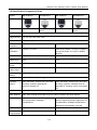
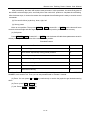
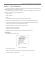
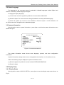
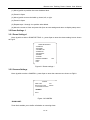
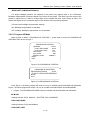
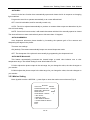
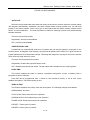
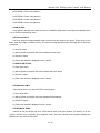
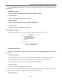
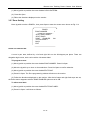
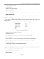
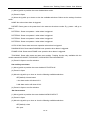
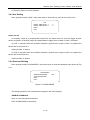
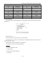
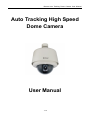
Bernee Auto Tracking Dome Camera User Manual Auto Tracking High Speed Dome Camera User Manual 1 / 39 Bernee Auto Tracking Dome Camera User Manual Contents SECTION1 INSTRUCTION ...................................................................................................................................... 3 1.1 PRODUCTION INTRODUCING ............................................................................................................................................ 3 1.2 CHARACTER .................................................................................................................................................................. 3 1.3 FUNCTION DESCRIPTION.................................................................................................................................................. 3 1.4 SPECIFICATION COMPARISON CHART .................................................................................................................................. 7 SECTION 2 NORMAL OPERATION ....................................................................................................................... 10 2.1 DOME DIAL‐UP SETTING ............................................................................................................................................... 10 SECTION 3 MENU CONFIGURATION ................................................................................................................... 13 3.1 MAIN MENU .............................................................................................................................................................. 13 3.2 SELECT LANGUAGE ....................................................................................................................................................... 14 3.3 SYSTEM INFORMATION .................................................................................................................................................. 14 3.4 DISPLAY SETUP ............................................................................................................................................................ 14 3.4.1 Display Setup ............................................................................................................................................... 14 3.4.2 Label Position ........................................................................................................................................ 15 3.5 DOME SETTINGS 1 ....................................................................................................................................................... 16 3.5.1 Dome Settings 1 .......................................................................................................................................... 16 3.5.2 Camera Settings .......................................................................................................................................... 16 3.5.3 Motion Setting .............................................................................................................................................. 20 3.5.4 Power Up ...................................................................................................................................................... 23 3.5.5 Presets Setting ............................................................................................................................................. 24 3.5.6 Patterns Setting ............................................................................................................................................ 25 3.5.7 Zone Setting ................................................................................................................................................. 26 3.5.8 Clears Setting ............................................................................................................................................... 27 3.5.9 Presets Number ........................................................................................................................................... 28 3.6 DOME SETTINGS 2 MENU ............................................................................................................................................. 28 3.6.1 Alarms ............................................................................................................................................................ 28 3.6.2 Alarms Setting .............................................................................................................................................. 29 3.6.3 Aux Setting .................................................................................................................................................... 31 3.6.4 Password Setting ......................................................................................................................................... 31 3.6.5 Windows Blanking ....................................................................................................................................... 32 3.6.6 Set Windows ................................................................................................................................................. 33 3.6.7 Edit Windows Location ................................................................................................................................ 34 3.6.8 Edit Windows Zoom..................................................................................................................................... 34 3.6.9 Heater Setting .............................................................................................................................................. 35 3.6.10 Cruise Setting ............................................................................................................................................. 35 3.6.11 Tracking Setting.......................................................................................................................................... 36 3.6.12 Tracking Boundary ..................................................................................................................................... 37 3.7 DOME LABEL .............................................................................................................................................................. 38 3.8 OTHER FUNCTIONS ...................................................................................................................................................... 39 2 / 39 Bernee Auto Tracking Dome Camera User Manual Section1 Instruction 1.1 Production Introducing The dome cameras feature high position resolution, high speed, low price and selectable communication protocols; widely used in surveillance system. 1.2 Character Built-in English OSD Menu, by which you can change dome parameter, set or call preset, and achieve auto tour, pattern, auto scan etc. The feature will define the activity when the dome parks. Integrated design making it high reliability. Auto panning function with 256 preset positions. RS-485 data communication. Low noise design. With its full 360º horizontal rotation, 180º vertical auto-flip to follow object and surveillance of any subject is constant and continuous. The speed can be adjusted automatically according to the zooming times. Auto focus, Auto white balance. Auto focus lens and auto white balance. BLC Function. Multi protocols (Pelco-P, Pelco-D, Kalate etc). Baud rate is changeable. Alarm input, Alarm output, Alarm action. The features password protection to prevent unauthorized changes to the dome setting. A set window can be reversed so that it is the only visible tilt area of the scene. The other parts of the tilt area of the scene will be blanked. Revolutionary motion tracking technology make it realize intelligent surveillance easily with the help of alarming function 1.3 Function Description (1) Setting the dome ID, Baud-rate and Protocol Every controlling command has a target camera Address, Baud-rate and Protocol, the camera 3 / 39 Bernee Auto Tracking Dome Camera User Manual only react the controlling command in accordance with its own Address, Baud-rate and Protocol. (2) Object tracking The dome can be manually controlled from the control system by using the joystick on the controller to move the camera up and down, right and left to follow objects under observation. In default status AUTO IRIS and AUTO FOCUS control of the lens will automatically adjust the picture image on alteration of the background illumination to get a best view. (3) Proportional Pan Proportional pan automatically reduces or increases the pan and tilt speeds in proportion to the zooming times. At telephoto zoom settings, the pan and tilt speeds will be slower for a given amount of joystick deflection then at wide zoom settings. This keeps the image from moving too fast on the monitor when there is a large amount of zoom. (4) Auto Flip When the dome camera tilts downward and goes just beyond the vertical, the dome camera rotates 180 degrees automatically. Afterwards, the dome camera starts moving upward even you still hold joystick in the down position. Once you let go of the joystick after the dome rotates, joystick control returns to normal operation. The auto-flip feature is useful for following a person who passes directly beneath the dome. (5) Setup and call Preset Preset function is that dome saves current horizontal angle and title angle of pan/tilt, zoom and position parameters into the memory. When necessary, dome calls up these parameters and adjusts Pan/Tilt/Zoom accordingly so that the camera goes to that position again. Operator can save and call up presets easily and promptly by using keyboard controller or infrared controller. This dome supports up to 256 presets. (6) Lens Control a. Zoom control User can adjust camera’s zoom wide or near by using controller and get desired image. b. Focus control System defaults Auto Focus mode, in which the lens and camera will automatically adjust the focus to give the best image. Focus can also be controlled manually from the controller if required. Press FOCUS NEAR or FOCUS FAR key to manually focus. Focus can be manually controlled via keyboard or matrix, please refer to control keyboard or matrix operation manual for detailed operation. When on manual focus status, operations such as adjusting positions or preset setting will resume the camera to auto focus status. 4 / 39 Bernee Auto Tracking Dome Camera User Manual The camera will not auto focus in the following status. Target is not in the center of image. Targets are in near and far at the same time. Target is of strong light object. Such as spotlight etc. Target is behind the glass with water drop or dust. Target moves too fast. Target is too big, such as wall. Target is too dark or vague. c. Iris control System defaults AUTO IRIS. Camera can adjust immediately according to the alteration of back ground illumination to get a steady image. Users may adjust Iris manually by using a controller to get required image quality. Users can call back AUTO IRIS by moving the joystick. (7) Auto Back-light Compensation Lens has been divided to six areas for back light compensation. In a strong light background, camera will auto compensate the darker object and adjust light input from the lighter area to avoid a mass image that usually presents a sharp contrast of brightness and darkness. (8) Auto White Balance Camera can automatically adjust white balance according to the alteration of background lightness to give a true color image. (9) Backlight Compensation (BLC) If a bright backlight presents, the subjects in the picture may appear dark or as a silhouette. Backlight compensation enhances objects in the center of the picture. The dome uses the center of the picture to adjust the iris. If there is a bright light source outside this area, it will change to white. The camera will adjust the iris so that the object in the sensitive area is properly exposed. (10) Day and Night Function The IR cut filter of camera module inside the dome can be removed by sending special command, so that the camera can change from color to mono. The picture is clear even if the illumination is as low as 0.01Lux. (11) Auto Cruise The preset positions are programmed for recalled in sequence. This feature is called auto cruise. Up 30 presets can be set in each cruise tour. (12) Patterns 5 / 39 Bernee Auto Tracking Dome Camera User Manual A pattern is a saved moving course; the camera will repeat its pan, tilt, zoom and preset functions that can be recalled with a command from a controller or automatically by a programmed function (alarm, park or power-up). (13) Auto Scan Make the dome scan 360º range in the current position. (14) Random Scan Make the dome random scan 360º range in the current position. (15) Frame Scan This feature freezes the scene on the monitor when going to a preset. This allows for smooth transition from one preset scene to another. (16) Zones Setting A zone is a pan area, defined by a left and right limit, on the 360-degree pan plane. The spectra dome system is capable of eight zones, each with a 6-character label. (17) Alarms Alarms input: The dome has four alarm inputs, which can be programmed as high, medium or low priority. When an alarm is received, an input signal to the dome triggers the user-defined action (go to preset, run pattern, etc.) programmed for the alarm. Auxiliary output: An auxiliary output is a programmable signal from the dome back box that can trigger another device to operate. An auxiliary output is programmable to trigger from an alarm or from a controller. (18) Password protection The dome features password protection to prevent unauthorized changes to the dome settings. You can open the System Information and Display Setup screens, but cannot access any of the Dome Settings menus. (19) Windows blank A set window can be reversed so that it is the only visible tilt area of the scene. All other parts of the tilt area of the scene will be blanked. NOTE: Be the same with only the model of KTSD18NX, KTSD26NX, KTST18NX, and KTST26NX. (20) Auto tracking Revolutionary motion tracking technology making it realize intelligent surveillance easily with the help of alarming function 6 / 39 Bernee Auto Tracking Dome Camera User Manual 1.4 Specification Comparison Chart Models BN-5606XAT1 BN-5606XAT3 BN-5606EAT1 BN-5606EAT3 Installation Indoor/Embedded Outdoor/ Wall mount Indoor/Embedded Outdoor/ Wall mount Auto Track Yes Image Sensor 1/4″ Ex-view HAD color CCD Effective Pixel 752(H)×582(V) Horizontal Resolution 480TV Lines On/Off (on: 530 TV lines) Min. illumination 0.002Lux, 0Lux/IR 1/60 second mode: 1.4Lux(F1.6,50IRE), 1/4 second mode: 0.1Lux(F1.6,50IRE), 0Lux/IR Optical Zoom 18X,f =4.1~73.8mm(F 1.4 to 3.0) 36X, f=3.4~122.4mm(F 1.6 to 4.5) Digital Zoom 12 X 12 X Min. Length 35mm(wide), 800mm(Tele) 320mm(wide), 1500mm(Tele) Horizontal Field of View 48°(wide)~2.8°(Tele) 57.8°(wide)~1.7°(Tele) Scanning System 2:1 interlace Sync System Internal / External (V-locking) Focusing System Auto (sensitivity: normal, low) / one-click focusing / manual / alternate AF / zoom-out activate AF Gain Control Auto / Manual (-3~28dB, 2dB stepping) White Balance Auto, auto tracking white balance (ATW), indoor, outdoor, one-click, manual AE Control Auto, manual, priority modes, brightness, EV compensation, backlight compensation Auto, manual, priority modes (shutter priority / aperture priority), brightness, EV compensation, backlight compensation, brightness compensation, slow AE Super WDR No On / Off Backlight Compensation On / Off On / Off Appearance Focal 7 / 39 Auto (sensitivity: normal, low) / one-click focusing / manual / unlimited zoom-in / alternate AF focusing / zoom-out activate AF Bernee Auto Tracking Dome Camera User Manual Electronic Shutter 1/1~1/10, 000 seconds, 22 speed-levels External Control VISCA(TTL signal power level), baud rate: 9.64Kb/s,19.24Kb/s,38.4Kb/s, stop position 1 or 2 optional Privacy Mask On/Off (24 zones) Picture Feature Electronic flip, backward flip, black & white, mirror Character Generator Mode display, clock display, title display Mode display / multi-line OSD (OSD display prior to mode display) Flicker Elimination No Auto Video Output CVBS: 1.0Vp-p/75 ohms SN Ratio ≥50dB Pan Speed 0.05°~400°/s Tilt Speed 0.03°~240°/s Pan Travel 360° continuous Tilt Travel 90°(180° auto-flip) Preset Positions 256 Auto Tour 1~30 point sequence switch Pattern Scan 4 Zone Setting 8 Control Modes Multi-protocol, RS485 Baud Rate 1200 bps/2400 bps/4800 bps/9600 bps/19200 bps Address Range 0~255 Alarm Input 4 channels Alarm Output 2 channels OSD Language Chinese/English Voltage Input AC24V Power Consumption 20W 50W 20W 50W Dimension 157×205mm(W×H) 238×268mm(W×H) 157×205mm(W×H) 238×268mm(W×H) Weight 2.3kg 3.8kg Working Temperature -25°C~70°C -50°C~70°C ON / OFF (8 zones) 3.8kg 8 / 39 -25°C~70°C -50°C~70°C Bernee Auto Tracking Dome Camera User Manual Relative Humidity 5%~90% 9 / 39 Bernee Auto Tracking Dome Camera User Manual Section 2 Normal Operation These operating instructions cover the basic operation of the dome and its features. When the dome is used with other manufacturers’ control system, please refer to the system controller’s instructions. In the event of special requirements outside the scope of this document it is prefer to contact your local distributor. 2.1 Dome Dial-up Setting Dome own parameters such like baud rate, communication protocol and address codes should accord with the practical parameters of customer’s operation platform (i.e. keyboard controller). Two groups of dial-up switchers lie in soleplate of dome engine SW1 (dial-up switcher) is used to select communication protocol or baud rate. The front four switchers are used to set communication protocol, and the latter four to set baud rate. Chart of Communication protocol & Baud rate DIP Protocol 1 2 3 4 OFF ON OFF OFF PELCO-P ON ON OFF OFF PELCO-D OFF OFF ON OFF KALATEL ON OFF ON OFF VICON OFF ON ON OFF SAMSUNG ON ON ON OFF AD OFF OFF OFF ON PHILIPS ON OFF OFF ON WEIDUO OFF ON OFF ON ALEC ON ON OFF ON MINKING OFF OFF ON ON LC …… DIP 5 6 7 8 1200 ON OFF OFF OFF 2400 OFF ON OFF OFF Baud Rate 4800 ON ON OFF OFF (bps) 9600 OFF OFF ON OFF 19200 ON OFF ON OFF Reserve …… SW2 (dial-up switcher) is used to set dome address codes. The setting adopts binary mode which can set max.256 different addresses for domes. Details in chart of dome address codes. Chart of Dome Address Codes 10 / 39 Bernee Auto Tracking Dome Camera User Manual Address 1 2 3 4 5 6 7 8 0 OFF OFF OFF OFF OFF OFF OFF OFF 1 ON OFF OFF OFF OFF OFF OFF OFF 2 OFF ON OFF OFF OFF OFF OFF OFF 3 ON ON OFF OFF OFF OFF OFF OFF 4 OFF OFF ON OFF OFF OFF OFF OFF 5 ON OFF ON OFF OFF OFF OFF OFF 6 OFF ON ON OFF OFF OFF OFF OFF 7 ON ON ON OFF OFF OFF OFF OFF 8 OFF OFF OFF ON OFF OFF OFF OFF 9 ON OFF OFF ON OFF OFF OFF OFF 10 OFF ON OFF ON OFF OFF OFF OFF 11 ON ON OFF ON OFF OFF OFF OFF 12 OFF OFF ON ON OFF OFF OFF OFF 13 ON OFF ON ON OFF OFF OFF OFF 14 OFF ON ON ON OFF OFF OFF OFF 15 ON ON ON ON OFF OFF OFF OFF 16 OFF OFF OFF OFF ON OFF OFF OFF 17 ON OFF OFF OFF ON OFF OFF OFF 18 OFF ON OFF OFF ON OFF OFF OFF 19 ON ON OFF OFF ON OFF OFF OFF 20 OFF OFF ON OFF ON OFF OFF OFF … … … … … … … … … 248 OFF OFF OFF ON OFF ON OFF OFF 249 ON OFF OFF ON OFF ON OFF OFF 250 OFF ON OFF ON OFF ON OFF OFF 251 ON ON OFF ON OFF ON OFF OFF 252 OFF OFF ON ON OFF ON OFF OFF 253 ON OFF ON ON ON ON ON ON 254 OFF ON ON ON ON ON ON ON 255 ON ON ON ON ON ON ON ON Finishing dial-up switchers, please insert dome engine into metal shell Precaution: 1. when inserting engine, we must ensure engine accordant with square slot inside shell, and then fix clips of both sides. 2. When fixing clips, we must ensure hearing two “click!”, otherwise fixing incorrect. 2.2 Basic Controls for Dome Below instructions are based on using control keyboard as controlling device. (1) Dome Self-testing after Powered up 11 / 39 Bernee Auto Tracking Dome Camera User Manual After powered up, the dome will conduct reset procedure. In this procedure, the dome firstly pans to the default horizontal origin point, and finally tilts to the vertical 45° position to complete the self-testing. After the dome stops, it means the camera has completed the self-testing and is ready to receive control commands. (2) Pan and tilt: Move joystick up, down, right, left. (3) Set up preset Move to next position. Then press PRESET + NUM (preset NO.)+ ENTER and the dome will save current horizontal angle and title angle of pan / tilt / zoom and position parameters into memory. (4) Call preset Press PRESET + NUM(Preset NO.)+ ENTER , and the dome will calls these parameters saved in memory and adjust Pan/Tilt/Zoom of the camera to that position. Extended Presets Presets 1 Function Presets 2 80 Auto tracking 37 82 Auto switch sequentially among preset positions 19 83 Clear all presets positions 20 95 Select main programming menu 28 97 Random scanning 30 98 Frame scanning 31 99 Start auto scanning 32 Note: For others dynamics controllers with only 64 or 40 presets. On the menu of PRESETS NUMBER, set it as 64 or 40. Then you can use presets listed in ‘Presets 2’ instead. (5) Zoom: You can press IN or OUT key continuously or revolve the joystick to get desired zooming times. (6) Focus: press FAR or NEAR key. (7) Iris: Press OPEN or CLOSE key. 12 / 39 Bernee Auto Tracking Dome Camera User Manual Section 3 Menu Configuration You need to install the dome system before using this manual. Please refer to the installation packet supplied with the back box for installation instructions. After installed properly, power up the camera. It will start a configuration sequence. After the configuration is done, the monitor will display as below. PTOL:PELCO-D COMM:2400,N,8,1 ADDR:0 This information will remain on the monitor until dome operation begins. Please refer to the following pages for more about how to operate and program the camera. Access main menu(preset 95): Please refer to the Accessing Main Menu(Preset 95) section. (1) Move joystick to position the cursor beside menu selection. (2) Move the joystick up or down to submenu/cursor selections. (3) Press iris Open to confirm selection. (4) Press iris Close to cancel selection. (5) Below instructions are based on using control keyboard as control device. 3.1 Main Menu Set 95# preset to access main menu. MAIN MENU < SYSTEM INFORMATION > < DISPLAY SETUP > < DOME SETTINGS 1> < DOME SETTINGS 2> <DOME LABLE> RESET CAMERA REBOOT SYSTEM LANGUAGE ENGLISH EXIT Figure 3.1 MAIN MENU Access other OSD menus: (1) Move the joystick up or down to position the cursor beside others OSD menus. (2) Press iris Open to confirm selection. 13 / 39 Bernee Auto Tracking Dome Camera User Manual 3.2 Select Language The language for the on-screen menus is selectable. Available languages include English and Chinese. The factory default language is English. Changing the display language: (1) In main menu move the joystick to position the cursor beside LANGUAGE. (2) Press iris Open. The cursor moves to the right, beside the currently selected language. (3) Move the joystick up or down to view selections. Press iris Open to confirm selection. All on-screen menus are changed into the selected language. 3.3 System Information Move joystick to select <system information>, press Open to confirm the system information menu shown as Fig 3.2. SYSTEM INFORMATION 9600,N,8,1 ADDRESS 255 PROTOCOL PELCO-P PRESETS NUMBER 256 LANGUAGE ENGLISH TEMPERATURE 36°C BACK EXIT COMM Figure 3.2 SYSTEM INFORMATION The system information screen shows dome language, protocol, and other configuration information. System information settings shown are not changeable in this interface. It is for reference only. Follow the following steps to display the system information screen: (1) Move the joystick to position the cursor beside SYSTEM INFORMATION. (2) Press iris Open. 3.4 Display Setup 3.4.1 Display Setup Move joystick to select <DISPLAY SETUP>, press Open to enter the display setup menu shown as Fig3.3. 14 / 39 Bernee Auto Tracking Dome Camera User Manual DISPLAY SETUP PRESET LABEL ON ZONE LABEL ON ZOOM ON AZIMUTH/ELEVATION ON CAMERA LABEL ON <LABEL POSITION> BACK EXIT Figure 3.3 DISPLAY SETUP Display setup enables you to program how labels are displayed on the monitor. The following labels are available: PRESET LABEL: Identifying preset. ZONE LABEL: Identifying zone. ZOOM: Identifying zooming times. AZIMUTH/ELEVATION: Amount of pan from 0°and the amount of tilt from 0°horizontal. CAMERA LABEL: Identifying dome. A preset label is displayed when a preset is called. A zone label is displayed when the system moves into a zone. The zoom ratio label is displayed when zoom is activated. Azimuth/elevation and direction labels are displayed when pan/tilt is activated. The dome label is displayed when the dome label is activated. The following settings are available for each label: OFF: The label is not displayed when activated. ON: The label shows when activated. 3.4.2 Label Position Labels can be placed anywhere on the monitor. This feature enables you to customize the place of labels on monitor screen. ZONE CAMERA PRESET SAVE RESET AZIMUTH ZOOM Figure 3.4 Label Position To set a label position: 15 / 39 Bernee Auto Tracking Dome Camera User Manual (1) Move joystick to position the cursor beside a label. (2) Press iris Open. (3) Move joystick to move the label up, down, left, or right. (4) Press iris Open. (5) Repeat steps 1 through 4 to position other labels. (6) Move the cursor to Save and press iris Open to save settings and return to display setup menu. 3.5 Dome Settings 1 3.5.1 Dome Settings 1 Move joystick to select <DOME SETTING 1>, press Open to enter the dome setting1 menu shown as Fig3.5. DOME SETTINGS1 <CAMERA> <MOTION> <POWER UP> <PRESETS> <PATTERNS> <ZONES> <CLEAR> PRESET NUMBER 256 BACK EXIT Figure 3.5 Dome settings 1 3.5.2 Camera Settings Move joystick to select <CAMERA>, press Open to enter the camera menu shown as Fig3.6. CAMERA ZOME LIMIT X46 BACKLIGHT COMP ON/OFF <PROGRAM AE MODE> <OTHERS> BACK Figure 3.6 CAMERA ZOOM LIMIT: Zoom limit enables you to define a limitation on zooming times. 16 / 39 Bernee Auto Tracking Dome Camera User Manual BACKLIGHT COMPENSATION(BLC): If a bright backlight presents, the subjects in the picture may appear dark or as a silhouette. Backlight compensation enhances objects in the center of the picture. The dome uses the center of the picture to adjust the iris. If there is a bright light source outside this area, it will change to white. The camera will adjust the iris so that the object in the sensitive area is properly exposed. There are two backlight compensation settings: ON: Backlight compensation is activated. OFF (default): Backlight compensation is not activated. 3.5.2.1 Program AE Mode Move joystick to select < PROGRAM AE CORTROL >, press Open to enter the PROGRAM AE CORTROL menu shown as Fig3.7 PROGRAM AE CORTROL AE MODE AUTO LOW LIGHT MODE AUTO LOW LIGHT LIMIT 1/50 IRIS LEVEL F2.0 AGC LEVEL 0dB BIRGHT LEVEL 0dB/F2.0 BACK EXIT Figure 3.7A PROGRAM AE CORTROL PROGRAM AE COORTROL PROGRAM AE MODE AUTO IR CUT FILTER INISERT/REMOVE BACK EXIT Figure 3.7 B PROGRAM AE CORTROL Note: Figure 1.7A shows program AE mode, it is only for models names NVD18XX and NVD26XX. Figure 1.7B shows program AE mode, it is only for models named NVD22XX and NVD23XXPNT. (Ⅰ) Figure 3.7A PROGRAM AE MODE setting for models named NVD18XX and NVD26XX. AE MODE: Settings include: AUTO, MANUAL , SHUTTER, IRIS, and BRIGHT. LOW LIGHT MODE: Settings include: AUTO and MANUAL. LOW LIGHT LIMIT: 17 / 39 Bernee Auto Tracking Dome Camera User Manual Low light limit is the maximum duration, it is in fractions of a second, that electronic shutter will remain open in low light conditions. The default setting is 1/50. Settings include:1/2, 1/3, 1/6, 1/12, 1/25, 1/50, 1/75, 1/100, 1/120, 1/150, 1/215, 1/300, 1/425, 1/600, 1/1000, 1/1250, 1/1750, 1/2500, 1/3500, 1/6500, 1/10000. IRIS LEVEL: Iris level is the lens function that automatically opens and closes the iris in response to changing light conditions. The default setting is F2.0. Settings include: F2.0, F1.6 , F1.4, Close, F22, F19, F16, F14, F11, F 9.6, F8.0, F6.8, F5.6, F4.8, F4.0, F3.4, F2.8, F2.4. AGC LEVEL: AGC(Automatic Gain Control) automatically adjusts the amount of video amplification to maintain a Full 1-volt peak-to-peak video signal output. The default setting is 0 dB. Settings include: 0dB, 2 dB, 4 dB, 6dB, 8 dB, 10 dB, 12 dB, 14 dB, 16 dB, 18 dB, 20 dB, 22 dB, 24 dB, 26 dB, 28 dB. BRIGHT LEVEL: The default setting is 0 dB /F2.0. Settings include: 0 dB /F2.0, 0 dB /F1.6, 0 dB /F1.4, 2 dB / F1.4, 4 dB / F1.4, 6 dB / F1.4, 8 dB / F1.4, 10 dB/ F1.4, 12 dB/ F1.4, 14 dB/ F1.4, 16 dB/ F1.4, 18 dB/ F1.4, 20 dB/ F1.4, 22 dB/ F1.4, 24 dB/ F1.4, 26 dB/ F1.4, 28 dB/ F1.4, Close, 0 dB /F22, 0 dB /F19, 0 dB /F16, 0 dB /F14, 0 dB /F11, 0 dB /F9.0, 0 dB /F 8.0, 0 dB /F6.8, 0 dB /F5.6, 0 dB /F4.8, 0 dB /F4.0, 0 dB /F3.4, 0 dB /F2.8, 0 dB /F2.4. NOTE: LOW LIGHT LIMIT, IRIS LEVEL, AGC LEVEL BRIGHT LEVEL can set only when AE MODE and LOW LIGHT MODE are set as Manual. (Ⅱ) Figure 3.7B PROGRAM AE MODE settings are for MODEL NVD18XX and NVD26XX. AE MODE: Settings include: AUTO, AU+IR1, AU+IR2, AU+DSS, AU+DSS+IR1, AU+DSS+IR2, AU+DSS+IR3, SHUTTER PR, IRIS PRIO, and AGC PRIORI. IR CUT FILTER: Settings include: IN and OUT. LOW LIGHT LIMIT: Settings include: 1/1.5, 1/3, 1/6, 1/12, 1/25, 1/50. SHUTTER: Settings include: 1/30000, 1/10000, 1/4000, 1/2000, 1/1000, 1/500, 1/250, 1/150, 1/100, 1/50, 1/25, 1/12, 1/6, 1/3, 1/1.5. IRIS LEVEL: 18 / 39 Bernee Auto Tracking Dome Camera User Manual Iris level is the lens function that automatically opens and closes the iris in response to changing light conditions. The default setting is F1.6. Settings include: F1.6, F2.2, F3.2, F4.4, F6.4, F8.8, F12, F17, F24, F34. AGC LEVEL: AGC(Automatic Gain Control) automatically adjusts the amount of video amplification to maintain a Full 1-volt peak-to-peak video signal output. The default setting is 0 dB. Settings include: 0dB, 6dB, 12dB, 18dB, 24dB, and 30dB 3.5.2.2 Other Menu Move joystick to select < others >, press Open to enter the others menu shown as Fig3.8. OTHERS IR CUT FILTER AUTO IR CUT FILTER COLOUR AUTO IRIS ON SHARPNESS ON SHARPNESS LEVEL 5 AUTO WHITE BALANCE ON/OFF R GAIN 214 B GAIN 164 BACK EXIT Figure 3.8A OTHER MENU OTHERS AUTO IRIS AUTO IRIS LEVEL AUTO IRIS PEAK SHARPNESS SHARPNESS LEVEL AUTO WHITE BALANCE R GAIN B GAIN BACK EXIT ON 91 16 ON 39 ON 652 427 Figure 3.8B OTHER MENU Note: Figure 3.8A shows Other Menu only for models named NVD18XX and NVD18XX. Figure 3.8B shows Other Menu only for the models named NVD22XX and NVD23XX. 19 / 39 Bernee Auto Tracking Dome Camera User Manual AUTO IRIS: Auto iris is the lens function that automatically opens and closes the iris in response to changing light conditions. Program the auto iris to operate automatically or at a user-defined level. OFF: Auto iris is disabled, and for manually control only. AUTO: The iris is adjusted automatically to produce a constant video output as determined by the Auto Iris level setting. NOTE: If auto iris is in auto mode, it will remain that status until the iris is manually opened or closed. The dome will return to auto mode when it pans or tilts more than 15 degrees. AUTO SHARPNESS: Auto sharpness enhances picture details by increasing the aperture gain of the camera and sharpening the edges in the picture. There are two settings: ON (default): The camera automatically keeps at a normal sharpness mode. OFF: The sharpness of the picture is set manually by programming the sharpness level. AUTO WHITE BALANCE: This feature automatically processes the viewed image to retain color balance over a color temperature range. The default setting for auto white balance is ON. R GAN: Adjusts the picture output in the red range. As you change the value, the color changes on your monitor. B GAN: Adjusts the picture output in the blue range. As you change the value, the color changes on your monitor. 3.5.3 Motion Setting Move joystick to select <MOTION >, press Open to enter the motion menu shown as Fig3.9. MOTION AUTO FLIP ON/OFF PROPORTIONAL PAN ON/OFF PARK TIME(MINUTES) 0 PARK ACTION NONE SCAN SPEED(DEG/S) 1 < SET SCAN> < MANUAL LIMIT> < SET AZIMUTH ZERO> < CLEAR AZIMUTH ZERO> BACK EXIT 20 / 39 Bernee Auto Tracking Dome Camera User Manual FIGURE 3.9 MOTION MENU AUTO FILP: When the dome camera tilts downward and goes just beyond the vertical, the dome camera rotates 180 degrees automatically. Afterwards, the dome camera starts moving upward even you still hold joystick in the down position. Once you let go of the joystick after the dome rotates, joystick control returns to normal operation. The auto-flip feature is useful for following a person who passes directly beneath the dome. There are two auto flip modes: ON(default): Auto flip mode enabled. OFF: Auto flip mode disabled. PROPORTIONAL PAN: Proportional pan automatically reduces or increases the pan and tilt speeds in proportion to the zooming times. At telephoto zoom settings, the pan and tilt speeds will be slower for a given amount of joystick deflection then at wide zoom settings. This keeps the image from moving too fast on the monitor when there is a large amount of zoom. There are two proportional pan modes: ON(default): Enables the proportional pan mode. OFF: Disables proportional pan mode. The pan speed will not depend on the zooming times. PARK TIME: This feature enables the dome to operate a specified activity(scan, preset, or pattern) after a programmed time of idleness. Park time can be programmed from 1 minute to 720 minutes(12 hours), or set to zero, which disables this feature. The default setting is zero. PARK ACTION: This feature will define the activity when the dome parks. The following settings are available: NONE(default): No action. AUTO SCAN: Dome starts auto scan operation. RANDOM SCAN: Dome starts frame scan operation. FRAME SCAN: Dome starts frame scan operation. PRESET 1: Dome goes to preset 1. PRESET 8: Dome goes to preset 8. 21 / 39 Bernee Auto Tracking Dome Camera User Manual PANTTERN 1: Dome runs pattern1. PANTTERN 2: Dome runs pattern2. PANTTERN 3: Dome runs pattern3. PANTTERN4: Dome runs pattern4. SCAN SPEED: Scan speed is that the dome will pan when in a FRAME SCAN mode. Scan speed is adjustable from 1 to 32 via the programming menu. SET SCAN STOPS: Set Scan Stops are programmable stops that limit the pan range of the dome. There must be two limits, a left and a right, to define an area. The dome reverses direction frame scanning when a limit stop is reached. To set scan stops: (1) Move joystick to position the cursor beside set scan stops. (2) Press iris Open. (3) Follow the directions displayed on the monitor. CLEAR SCAN STOPS: To clear scan stops: (1) Move joystick to position the cursor beside clear scan stops. (2) Press iris Open. (3) Follow the directions displayed on the monitor. SET MANUAL LIMIT: <Set manual limit > is to set the P/T/Z’s moving range. To set manual limit: (1) Move joystick to position the cursor beside set manual limit. (2) Press iris Open. (3) Follow the directions displayed on the monitor. SET AZIMUTH ZERO: Azimuth is the pan angle from 0°to 359°.Azimuth zero is the pan position you specify to be the 0°point. Azimuth zero is normally set to magnetic north. Once set, azimuth and compass readings are based on the set Azimuth Zero point. 22 / 39 Bernee Auto Tracking Dome Camera User Manual To program azimuth zero: (1) Move joystick to position the cursor beside set azimuth zero. (2) Press iris Open. (3) Follow the directions displayed on the monitor. CLEAR AZIMUTH ZERO: (1) Move joystick to position the cursor beside CLEAR AZIMUTH ZERO. (2) Press iris Open (3) Follow the directions displayed on the monitor. 3.5.4 Power Up Move joystick to select <power up>, press Open to enter the power up menu shown as Fig3.10. POWER UP POWER UP ACTION NONE BACK EXIT FIGURE 3.10 POWER UP POWER UP ACTION: This setting defines a specific activity(scan, preset, pattern) to be performed after the dome is powered up. Following settings are available: NONE(default): No action. AUTO SCAN: Dome starts auto scan operation. RANDOM SCAN: Dome starts random scan operation. FRAME SCAN: Dome starts frame scan operation. PRESET 1: Dome goes to preset 1. PRESET 8: Dome goes to preset 8. PATTERN 1:Dome runs pattern 1. PATTERN 2:Dome runs pattern 2. PATTERN 3:Dome runs pattern 3. PATTERN 4:Dome runs pattern 4. 23 / 39 Bernee Auto Tracking Dome Camera User Manual 3.5.5 Presets Setting Move joystick to select <PRESETS>, press Open to enter the presets menu shown as Fig3.11. PRESETS PRESET NUMBER 1 …PRESET NOT DEFINEO… < EDIT PRESET LABEL > < EDIT PRESET SCAENE > < CLEAR PRESET > BACK EXIT Figure 3.11 PRESET The dome camera has 64 programmable preset positions. Follow below steps to program a preset. (1) Select preset number a. Move joystick to position the cursor beside PRESET NUMMBER, press iris Open. b. Move the joystick up or down to view selections. Press iris Open to confirm selection. (2) Edit preset label a. Move joystick to position the cursor beside EDIT Preset label. b. Press iris Open. It will show: PRESET NUMBER PRESET LABLE 1----0123456789YZ yz 1 ABCDEFGHIJKLMNOPQRSTUVWX abcdefghIjklmnopqrstuvwx INPUT MODE OK CN SP CHARACTER BP Figure 3.12 CHARACTER INPUT c. Move joystick to position the cursor beside a character. Press iris Open to confirm selection. To clear a character, position the cursor beside BPE, and then press iris Open. d. After the label is inputted, move the cursor to Ok, then press iris Open to save and return to the Preset menu. 24 / 39 Bernee Auto Tracking Dome Camera User Manual e. After the label is inputted, move the cursor to CE, then press iris Open to cancel and return to the Preset menu. (3) Edit preset scene a. Move joystick to position the cursor beside EDIT PRESET SCENE. b. Press iris Open. c. Follow the direction displayed on the monitor. (4) Clear a preset a. Move joystick to position the cursor beside CLEAR PRESET. b. Press iris Open. c. Follow the direction displayed on the monitor. 3.5.6 Patterns Setting Use stick to select <patterns> Open to enter the patterns menu shown as Fig3.13. PATTERNS PATTERN NUMBER <PROZGRSM PATTERN> <CLEARE PATTERN> BACK EDIT 1 Figure 3.13 PATTERNS PROGRAME PATTERN: A pattern is function that the camera can save its moving course, and will repeat that course when demanded. To program a pattern: (1) Move joystick to position the cursor beside PATTERN NUMBER, and then press iris Open. (2) Move the joystick up or down to view selections. Press iris Open to confirm selection. (3) Move joystick to position the cursor beside PROGRAM PATTERN. (4) Press iris Open. (5) Follow the directions displayed on the monitor. After a pattern is programmed, the remaining storage percentage will be displayed on the screen. This is the amount of memory available to program the remaining patterns. CLEAR PATTERN: 25 / 39 Bernee Auto Tracking Dome Camera User Manual (1) Move joystick to position the cursor beside CLEAR PATTERN. (2). Press iris Open. (3) F0llow the directions displayed on the monitor. 3.5.7 Zone Setting Move joystick to select <ZONES>, then press Open to enter the zones menu shown as Fig 3.14. ZONES ZONE NUMBER 1 …ZONE NOT DEFINEO… <EDIT ZONE LABEL> <EDIT ZONE> ZONE ENABLED ON <CLEAR ZONE > BACK EXIT FIGURE 3.14 ZONES SETTING A zone is pan area, defined by a left and right limit on the 360-degree pan plane. There are altogether eight zones, each can be with a 6-character label. TO program a zone: (1) Move joystick to position the cursor beside ZONE NUMBER. Press iris Open. (2) Move the joystick up or down to view selections. Press iris Open to confirm selection. (3) Move joystick to position the cursor beside EDIT ZONE. (4) Press iris Open. The Zone programming window will show on the monitor. (5) Follow the directions displayed on the monitor. After the left stops and right limit stops are set, the Zones menu reappears with the ZONE ENABLED option set to be ON. To edit a zone label: (1) Move joystick to position the cursor beside EDIT ZONE LABEL. (2) Press iris Open. It will show as follows: 26 / 39 Bernee Auto Tracking Dome Camera User Manual ZONE LABLE 0123456789YZ ZONE NUMBER 1----yz 1 ABCDEFGHIJKLMNOPQRSTUVWX abcdefghIjklmnopqrstuvwx INPUT MODE OK CN SP CHARACTER BP Figure 3.15 ZONE SETTING (3) Move joystick to position the cursor beside a character. Press iris Open to confirm selection. To clear a character, position the cursor beside BP, and then press iris Open. (4) When a label is inputted, move the cursor to Ok, then press iris Open to save and return to the Preset menu. (5) When a label is inputted, move the cursor to CN, then press iris Open to cancel and return to the Preset menu. To clear a zone: (1) Move joystick to position the cursor beside CLEAR ZONE. (2) Press iris Open. Follow the instructions on the screen. Note: The ZONE NUMBER 9 is the dome’s label. 3.5.8 Clears Setting Move joystick to select <CLEARS>, then press Open to enter the clears menu shown as Fig 3.16. CLEARS CLEAR ZONES CLEAR PARESETS CLEAR PATTERNS RESTORE FACTORY DEFAULTS BACK Figure 3.16 CLEARS SET CLEAR ZONES: Clear all zones. To clear a specific zone, please refer to ZONES section. LEAR PRESETS: 27 / 39 Bernee Auto Tracking Dome Camera User Manual Clear all presets. To clear a specific preset, please refer to the PRESETS section. CLEAR PATTERNS: Clear all patterns. To clear a specific pattern, please refer to the PATTERNS section. RESTORE FACTORY DEFAULTS: This is to restore leaving-factory’s default settings. 3.5.9 Presets Number This is to set the dome’s preset number. 3.6 Dome Settings 2 Menu Move joystick to select <DOME SETTINGS 2>, then press Open to enter the dome settings 2 menu shown as Fig 3.17. DOME SETTINGS 2 <ALARMS> <AUX> <PASSWORD> <WINDOWS BLANKING> <HEATER SETTING> CRUISE SETTING TRACKING SETTING BACK EXIT Figure 3.17 DOME SETTINGS 3.6.1 Alarms Move joystick to select <ALARMS>, then press Open to enter the alarms menu shown as Fig 3.18. ALARMS ALARM NUMBER SEQUENCE(SECS) < ALARM SETTINGS > <CLEAR SET> BACK EXIT 1 1 Figure 3.18 ALARMS The dome has seven alarm inputs, which can be programmed as high, medium or low priority. When an alarm is received, the inputted signal to the dome triggers the user–defined action(go to preset, run pattern, etc.) programmed for the alarm. 28 / 39 Bernee Auto Tracking Dome Camera User Manual There are three alarm settings: ALARM NUMBER: Use this to select alarms number. SEQUENCE<SECS>: This is the time the dome will perform an alarm activity when more than one alarm of the same priority occurs at the same time. RESET DELAY<SECS>: This is the length of time the dome considers the alarm to be active after it has physically cleared. 3.6.2 Alarms Setting Move joystick to select <ALARM NUMBER>, then press Open to enter the alarm number menu shown as Fig 3.19. ALARM NUMBER ALARM PRIORITY ALARM ACTION ACTIVATE AUX ALARM CONTACT BACK EXIT 1 LOW NONE OPEN OPEN Figure 3.19 ALARM SETTINGS Follow below steps to program alarm settings. Select alarm number: (1) a. Move joystick to position the cursor the cursor beside ALARM NUMBER. b. Press iris Open. c. Move the joystick up or down to view selections. Press iris Open to confirm selection. (2) Move the joystick to position the cursor beside Alarm Settings. Press iris Open. Select alarm priority: (1) Move joystick to position the cursor beside Alarm Priority. (2) Press iris Open. (3) Move the joystick up or down to view the available selections. Available settings include HIGH, MEDIUM, and LOW(default). If multiple alarms with different priorities are active at the same time, the dome will only go to the alarms with the highest priority. (4) Press iris Open to confirm selection. Set alarm action: 29 / 39 Bernee Auto Tracking Dome Camera User Manual (1) Move joystick to position the cursor beside Alarm action. (2) Press iris Open. (3) Move the joystick up or down to view the available selections. Below are the settings for alarm action: NONE: No action when alarm is triggered. PRESET: Dome goes to the preset that is the same as the alarm number. E.g. preset 1 will go to Alarm 1. PATTERN 1: Dome runs pattern 1 when alarm is triggered. PATTERN 2: Dome runs pattern 2 when alarm is triggered. PATTERN 3: Dome runs pattern 3 when alarm is triggered. PATTERN 4: Dome runs pattern 4 when alarm is triggered. AUTO SCAN: Dome starts auto scan operation when alarm is triggered. RANDOM SCAN: Dome starts RANDOM scan operation when alarm is triggered. FRAME SCAN: Dome starts FRAME scan operation when alarm is triggered. TRACKING: Dome calls preset and start auto tracking. Tracking function only available with the models named NVD18XXPT, NVD22XXPT, NVD23XXPNT and NVD26XXPNT. (4) Press iris Open to confirm selection. Set auxiliary to activate: (1) Move joystick to position the cursor beside ACTIVATE AUX. (2) Press iris Open. (3) Move the joystick up or down to view the following available selections. OFF(default): Not activated. 1: An alarm action will close AUX 1. 2: AN alarm action will close AUX 2. (4) Press iris Open to confirm selection. Set alarm contact: (1) Move joystick to position the cursor beside ALARM CONTACT. (2) Press iris Open. (3) Move the joystick up or down to view the following available selections. OFF(default): close ON: open. 30 / 39 Bernee Auto Tracking Dome Camera User Manual (4) Press iris Open to confirm selection. 3.6.3 Aux Setting Move joystick to select <AUX>, then press Open to enter the aux menu shown as Fig 3.20. AUX DWELL TIME<SECS> 1 DWELL TIME<SECS> 2 BACK EXIT 0 0 FIGURE 3.20 AUX An auxiliary output is a programmable signal from the dome back box that can trigger another device to operate. An auxiliary output is programmable to trigger from an alarm or from a controller. An AUX 1 command from the controller will place a ground at the output of AUX 2 to operate the device that is connected to it. Setting include: 0~30secs. An AUX 2 command from the controller will place a ground at the output of AUX 2 to operate the device that is connected to it. Setting include: 0~30secs. 3.6.4 Password Setting Move joystick to select <PASSWORD>, then press Open to enter the password menu shown as Fig 3.21. PASSWORED EBABLE PASSWORD <EDIT PASSWORD> BACK EXIT OFF Figure 3.21 PASSWORED This setting protects it from unauthorized changes to the dome settings. ENABLE PASSWORD: Open or close the password features. EDIT PASSWORD(Four Numbers): 31 / 39 Bernee Auto Tracking Dome Camera User Manual PLEASE INPUT OLD PASSWORED PASSWORD 1234567890 CLEAR ENTER EXIT Figure 3.22 EDIT PASSWORD (1) Move joystick to position the cursor beside a number. Press iris Open to confirm selection. (2) When password is inputted, move the cursor to ENTER and press iris Open comes to the PLEASE INPUT NEW PASSWORED. (3) Input four new passwords, move the cursor to ENTER then press iris Open and comes to PLEASE INPUT NEW PASSWORED. Input four new passwords. 3.6.5 Windows Blanking Move joystick to select <WINDOWS BLANKING>, then press Open to enter the windows blanking menu shown as Fig 3.23. WINDOWS BLANKING STYLE GRAY BLANK ALL ABOVE OFF BALANK ALL BELOW OFF <SET WINDOWS> BACK EXIT Figure 3.22 WINDOWS BLANKING Window blanking enables you to program up to eight, four-sided, user-defined areas that cannot be viewed by the operator of the dome system. A blanked area will move with pan and tilt functions and automatically adjust in size according to zoom times. Style: The dome has two styles for window blanking, GRAY and SMEAR. If style is set to gray, the blanked area is covered with a solid gray window. If smear is selected images behind the window will be noticeable but not distinguishable. BLANK ALL ABOVE/BLANK ALL BELOW: The dome camera has two style modes for window blanking, GRAY and SMEAR. If style is set to gray, the blanked area is covered with a solid gray window. If smear is selected images behind the window will be noticeable but not distinguishable. Blanking Parameters: 32 / 39 Bernee Auto Tracking Dome Camera User Manual BLANK ALL ABOVE BLANK ALL BELOW OFF No Blanking OFF No Blanking 0 -5º~10º 0 5º~92º 10 -5º~25º 20 -5º~35º 20 5º~92º 30 -5º~45º 30 15º~92º 40 -5º~55º 40 25º~92º 50 -5º~65º 50 35º~92º 60 -5º~75º 60 45º~92º 70 -5º~85º 70 55º~92º 80 -5º~95º 80 70º~92º -5º~92º 10 3.6.6 Set Windows Move joystick to select <SET WINDOWS>, then press Open to enter the set windows menu shown as Fig 3.24. SET WINDOWS WINDOWS NUMBER 1 <EDIT WINDOWS LOCATION> <EDIT WINDOW ZOOM > ENABLE WINDOWS OFF CLEAR WINDOWS BACK EXIT Figure 3.24 SET WINDOWS MENU Windows Number: 1 ~ 8. <Edit windows location>: Edit the location of windows blanking <Edit window zoom>: set the zoom of the blanking. The blanking will take effect when the video is zoomed to this time or above. Enable Windows: Enable or disable the current blanking Clear windows: clear the current windows blanking Operation: 1. Move joystick to select a item 2. Press iris Open 3. Move joystick to select parameters 4. Press Open 33 / 39 Bernee Auto Tracking Dome Camera User Manual 3.6.7 Edit Windows Location Move joystick and move cursor to < EDIT WINDOWS LOCATION >, then press open to enter the menu as Fig 3.25. EDIT WINDOWS LOCATION IRIS OPEN TO CONTINUE IRIS CLOSE TO CANCEL Figure 3.25 EDIT WINDOWS MENU Operation: 1. From Fig 3.25, move cursor to make sure it is at the center points of blanking and coordinate. 2. From the menu of Fig. 3.25, press Close to return to the menu of Fig 3.24 3. From the menu of Fig. 3.25, press Open to enter menu of Fig 3.26 to edit the windows location. EDIT WINDOW LOCATION Figure 3.26 EDIT WINDOW LOCATION 4. From the EDIT WINDOW LOCATION menu shown in Fig 3.26: Move joystick left; zoom in (left/right) from the zone center. Move stick right; zoom in (left/right) from the zone center. Move stick up; zoom in (up/down) from the zone center. Move stick down; zoom in (up/down) from the zone center. 5. After the zone is set, press Open to save the settings and return to menu of Figure3.24. 3.6.8 Edit Windows Zoom From the menu of Figure 3.24, move stick and move cursor to <Edit Window Zoom>, press Open to enter below menu: EDIT WINDOWS IRIS OPEN TO CONTINUE IRIS CLOSE TO CANCEL Figure 3.27 EDIT WINDOWS Pan the joystick to adjust the zoom times. 34 / 39 Bernee Auto Tracking Dome Camera User Manual Press Close to discard the setting and return to Fig 3.24 Press Open to save the setting and return to Fig 3.24. 3.6.9 Heater Setting From the dome setting 2 menus shown in Fig3.17, move joystick and move cursor to HEATER SETTING, press Open to enter the following menu (Figure 3.28). HEATER SETTING HEATER DISPLAY ON HEATER MODE AUTO TEMPERATUEE SET 33℃ BACK EXIT Figure 3.28 HEATER SETTING HEATER DISPLAY: Heater display shows heater state. ON: Screen will display heater state. OFF: Screen will not display heater state. HEATER MODE: Heater mode is to set the heater’s startup mode. AUTO: Heater starts when temperature is lower than lower temperature. OFF: Heater is closed. ON: Heater is open. TEMPERATURE SET: Temperature set is to set the heater’s startup temperature. Operations: 1. Move joystick to select an item. 2. Press Open. 3. Move the stick to select a parameter. 4. Press Open. 3.6.10 Cruise Setting From the menu shown in Fig3.17, move joystick to select <CRUISE SETTING>, press Open to 35 / 39 Bernee Auto Tracking Dome Camera User Manual enter the following menu. CRUISE DWELL TIME<SECS> PRESET LIST 1 ON 0 OFF 1234567890 0110010111 BACK EXIT 7 1 Fig 3.29 CRUISE Dwell Time: the lasting time of preset, from 5~250 seconds Preset List: parameter 1, 2, 3 Operations: 1. In the menu, move the joystick to select a specific item. 2. Press Open. 3. Select the parameter with the joystick. 4. Press Open 1 ON 0 OFF: Note, they are not changeable, 1234567890: display info, not changeable. When the preset list is 1, “1, 2, 3, 4, 5, 6, 7, 8, 9, 0” indicates presets from 1 ~ 10. When it is 2, it indicates presets from 11 ~ 20. When it is 3, it indicates presets from 21 ~ 30. 0 0 0 0 0 1 0 1 0 1: select the cruising presets. 1 for cruising, 0 for not cruising. Operations: 1.From the menu in Fig3.21, select relative item of “1234567890” with the joystick. 2. Press Open and select a specific parameter. Select options with joystick. 3.6.11 Tracking Setting Move joystick to select <TRACKING SETTING>, press Open to enter the tracking menu shown as Fig 3.30. 36 / 39 Bernee Auto Tracking Dome Camera User Manual TRACKING SETTING DEFAULT SETTING SIZE SNS MIDIUM GRAY SNS MIDIUM LOST ACT TO HOME & TRACKING AUTO ZOOMING ON WAIT TINE<S> 40 <TRACKING BOUNDARY> BACK EXIT Figure 3.30 TRACKING SETTING Default Setting: tracking setting to default. Size SNS: the size of the target in the screen, Medium, Large, and Small are selectable GRAY SNS: the sensitivity of the moving object, Medium, High and Low are selectable LOST AC: the action when the moving object is lost. Parameters include: return home and tracking, keep tracking, stop tracking AUTO ZOOMING: The dome will auto zoom in / out according to the size and distance of the object. Parameters can be ON/OFF. WAIT TIME <S>: When the tracking object is lost, the interval of time for the dome to wait before Lost Action. Parameters can be 5, 10, 15, 20, 25, 30, 35, 40 seconds. <TRACKING BOUNDARY>: to set the valid area of tracking function (UP/DOWN/LEFT/RIGHT). Operations: 1. In the menu of Fig 3.30, move joystick to a specific item 2. Press Open 3. Move joystick to select desired parameter 4. Press Open 3.6.12 Tracking Boundary From the menu in Fig3.30, move the cursor to < TRACKING BOUNDRAY >, press Open to enter the following menu (Figure 3.31) 37 / 39 Bernee Auto Tracking Dome Camera User Manual TRACKING BOUNDARY BOUNDARY LIMIT CLEAR BOUNDARY LEFT LIMIT RIGHT LIMIT UP LIMIT DOWN LIMIT BACK EXIT OFF OFF OFF OFF OFF Figure 3.31 TRACKING BOUNDARY BOUNDAR LIMIT: enable / disable the boundary CLEAR BOUNDARY: clear setting of the current boundary LEFT LIMT: set the left tracking boundary RIGHT LIMT: set the right tracking boundary UP LIMT: set the up tracking boundary DOWN LIMT: set the down tracking boundary Operations: 1. Move the cursor to a specific function item 2. Press Open 3. Move the joystick to select parameter or operate as per screen instructions 3. Press Open 3.7 Dome Label From the menu shown in Fig3.1, move the cursor to <DOME LABEL>, press Open to enter the following menu (Figure .32) DOME LABLE <EDIT DOME LABEL> <CLEAR DOME LABEL> BACK EXIT Figure 3.32 DOME LABLE <EDIT DOME LABEL>: To edit the dome description and information. Please refer to 3.5.4 Edit Preset Label”. <CLEAR DOME LABLE>: Clear current dome label. Press Open to enter the menu and then operate with instructions. 38 / 39 Bernee Auto Tracking Dome Camera User Manual 3.8 Other Functions RESET CAMERA: If the camera does not operate or if you close camera’s control, cycle camera power. Cycling camera power resets the camera but does not change any saved camera settings. REBOOT SYSTEM: Reboot the system if it does not operate or if there is no control. Rebooting the system will cycle dome and camera power without changing programmed dome settings. 39 / 39