1
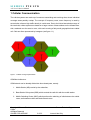
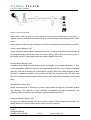
Local Service Organization Service Manual
BE INSPIRED
SIEMENS COMMUNICATIONS UNLIMITED
Our innovation shapes the future
SIEMENS PTE LTD
A55 Level 2 Service Manual
Table of Contents
1
CELLULAR COMMUNICATION…………………………………………………….2
1.1
Subscriber Identity Module (SIM)…….………………………………………………………..4
2
WIRELESS APPLICATION PROTOCOL (WAP)………………………………….6
3
KEY FEATURES………………………………………………………………………8
4
COMPARISON WITH PERVIOUS PRODUCT……………………………………10
5
ACCESSORIES………………………………………………………………………11
6
5.1
Interface A55 with Accessories……………………………………………………………….11
5.2
Accessories Part Numbers……………………………………………………………………12
UNIT DESCRIPTION A55 PIRANHA………………………………………………13
6.1
Exploded View of A55 Piranha……………………………………………………………….14
7
DISASSEMBLY OF A55.......………………………………………………………..15
8
REASSEMBLY OF A55……………………………………………………………..17
9
MOBILE SOFTWARE PROGRAMMING………………………………………….18
9.1
Mobile Software Updating…………………………………………………………………….19
9.2
Flow Chart for Software Updating……………………………………………………………20
10
SIEMENS SERVICE EQUIPMENT USER MANUAL…………………………….21
11
PICS INTERNET……………………………………………………………………..22
12
INTERNATIONAL MOBILE EQUIPMENT IDENTITY, IMEI…………………….27
13
GENERAL TESTING INFORMATION…………………………………………….28
Copyright © Siemens Pte Ltd.
Centre
All Rights Reserved
ICM MP CCQ ASP/ASC
Siemens Technical Support
1 of 33
Internal Use Only
SIEMENS PTE LTD
A55 Level 2 Service Manual
1 Cellular Communication
The cellular systems are made up of numerous transmitting and receiving sites, whose individual
coverage areas partially overlap. The concept of frequency reuse, same frequency is used by
several sites, allows a high traffic density in a wide area. Due to the limited transmission range of
the terminals, cellular systems are based on a large number of base stations on the infrastructure
side, scattered over the area to cover, with each covering a fairly small geographical zone called
cell. Cells are often represented by hexagons (see figure 1.1).
Figure 1.1 Cellular coverage representation.
GSM Net Architecture
GSM network can be broadly divided into three broad parts, namely:
1. Mobile Station (MS) carried by the subscriber,
2. Base Station Sub-system (BSS) which controls the radio link with the mobile station.
3. Mobile Switching Centre (MSC) which performs the switching of calls between the mobile
users, and between mobile and fixed network users.
Copyright © Siemens Pte Ltd.
Centre
All Rights Reserved
ICM MP CCQ ASP/ASC
Siemens Technical Support
2 of 33
Internal Use Only
SIEMENS PTE LTD
A55 Level 2 Service Manual
FIGURE 1.2 GSM ARCHITECTURE
Each mobile station is given a unique identity. As soon as the mobile phone is turned on, it
registers with the network and is authenticated; as such the network could always find the mobile
phone.
Larger amount of data is being exchanged to and from the following functional blocks in the MSC:
Visitor Location Register, VLR
Stores information about mobile subscribers that enter it coverage area, which is associated with
the geographical area where the mobile is currently roaming. When there is an incoming call for
the mobile, the HLR is interrogated about the present address of the VLR.
Home Location Register, HLR
A database that contains all data concerning the subscription of the mobile subscriber, i.e. their
access capabilities, subscribed services, and supplementary services. It also contains information
about the VLR that is handling the mobile station currently. When the mobile changes location,
the HLR is updated accordingly. It also provides the MSC with information about the MSC area
where the mobile is actually located to allow incoming calls to be routed immediately to the called
party.
Authentication Centre, AUC
Stored information that is necessary to protect communication through the air interface against
any intrusions. The legitimacy of the subscriber is established through authentication and
ciphering, which protects the user information against unwanted disclosure.
Equipment Identity Register, EIR
An option the network operator can use to enforce security. With this feature the network can
identify defective or stolen mobile that may not be used in the network.
Copyright © Siemens Pte Ltd.
Centre
All Rights Reserved
ICM MP CCQ ASP/ASC
Siemens Technical Support
3 of 33
Internal Use Only
SIEMENS PTE LTD
A55 Level 2 Service Manual
1.1
Subscriber Identity Module (SIM)
SIM is a smart card, which has a computer, and memory chip that is permanently installed in the
mobile equipment. It comes in either the size of a credit card or smaller version known as the
plug-in SIM.
The subscriber information, which includes a unique number called the International Mobile
Subscriber Identity (IMSI), is stored in the SIM card. SIM card identifies the subscriber to the
network.
To protect the SIM card from improper use, a security feature, a four digits personal identification
number (PIN), is built in. The PIN is stored in the SIM card and can be changed by the
subscriber. PIN2 is required for additional functions available with a special SIM card (Consult the
operator for more information about the PIN 2).
A code (PUK) is provided for unlocking the SIM card if the SIM card is blocked
SIM Application Toolkit
This is a new GSM feature that has been integrated into the GSM standards in Release 96, with
further enhancements added as part of the Release 97 feature set. This feature came about
because of a desire by Network Operators to offer differentiated services, without the need for the
Mobile Manufacturers having to build different variant for different customers. The unique service
offered by the Operator is placed as an application on the SIM and that could work on any mobile
that supports the Toolkit feature.
There is a distinct set of commands between the mobile and the SIM specifically for the Toolkit
that allows the SIM Toolkit and the mobile to communicate independently of the GSM
communication between the SIM and the mobile. Henceforth, the SIM Application Toolkit and
Copyright © Siemens Pte Ltd.
Centre
All Rights Reserved
ICM MP CCQ ASP/ASC
Siemens Technical Support
4 of 33
Internal Use Only
SIEMENS PTE LTD
A55 Level 2 Service Manual
GSM functionality on the SIM are separated logically. The Toolkit can interact directly with the
mobile itself and adding itself to the mobile menu.
Currently, Toolkit application on the SIM and its “other half” communicate by using the Short
Message Service (SMS). “Proactive SIM” is a mechanism whereby the SIM can initiate actions to
be taken by the mobile. These actions include:
·
Display text from the SIM on the Mobile display
·
Send short message
·
Set up a voice call to a number held by the SIM
·
Set up a data call to a number and bearer capabilities held by the SIM
·
Send a Supplementary Service (SS) control or Unstructured Supplementary Services Data
(USSD) string
·
Play a tone in the mobile’s ear piece or ringer
·
Initiate a dialogue with the user
·
Provide local information from the mobile to the SIM.
·
Data download to the SIM from network
·
Call control by the SIM.
SIM Applications Toolkit (SAT) allows the flexibility to update the SIM, to change the services and
download new services over the air. In the SAT specification, the short message service is a key
mechanism for personalizing the SIM in each user’s GSM phone. It is designed as a client-server
application. C45 series supports SAT Class 3 specification.
When active, the name of the service may appear in the menu, and there will be sub-menu if
more than one application is active. Figure 1.4 is the SAT icon.
FIGURE 1.4 SAT ICON
Extended GSM 900, E-GSM
This is a new standard that allows Network Operators to increase their capacity through an
extended frequency. The frequency range of E-GSM is as follows:
·
Mobile Transmit: 880,2 - 914,8 MHz
· Mobile Receive: 925,2 - 959,8 MHz
Copyright © Siemens Pte Ltd.
Centre
All Rights Reserved
ICM MP CCQ ASP/ASC
Siemens Technical Support
5 of 33
Internal Use Only
SIEMENS PTE LTD
A55 Level 2 Service Manual
A55 is a GSM Phase 2 / Phase 2+ Dual band E-GSM / GSM 1800 mobile phone.
2
Wireless Application Protocol, WAP
Wireless Application Protocol takes a client-server approach that uses the in-built micro-browser
to make a request, in wireless mark-up language (WML), for information or service. The request
is passed to a WAP Gateway, which then retrieves the information from an Internet server, in
HTML format, and translates it into WML. The requested information is then sent to from the
WAP Gateway to WAP client (mobile) using the available and most appropriate mobile network
bearer services.
Wireless Protocol Stack.
Wireless Application Environment (WAE)
Wireless Session Protocol (WSP)
Wireless Transaction Protocol (WTP)
Wireless Transport Layer Security (WTLS)
Wireless Datagram Protocol (WDP)
Bearers e.g. Data, SMS, USSD
TABLE 1.1 WAP PROTOCOL STACK
1. Wireless Application Environment
Defines the user interface on the phone. WAE contains the WML, WML script and the
wireless telephony application (WTA).
2. Wireless Session Protocol
Link the WAE to two session services – one connection oriented operating above the WTP
and a connectionless service operating above WDP.
3. Wireless Transaction Protocol
Runs on top of the datagram service and part of the standard suite of TCP/IP protocols, to
provide a simplified protocol suitable for low bandwidth mobile station.
Copyright © Siemens Pte Ltd.
Centre
All Rights Reserved
ICM MP CCQ ASP/ASC
Siemens Technical Support
6 of 33
Internal Use Only
SIEMENS PTE LTD
A55 Level 2 Service Manual
4. Wireless Transport Layer Security
WTLS incorporates security features that are based upon the established Transport layer
Security (TLS) protocol standard, that include data integrity checks, privacy on the WAP
Gateway to client leg and authentication.
5. Wireless Datagram Protocol
Allows WAP to be bearer independent by adapting the transport layer of the under-laying
bearer. WDP presents a consistent data format to the higher layer on the WAP stack.
WAP Internet access via the A55 is possible with the inclusion of Wireless Application Protocol
(WAP) browser 1.2.1
Copyright © Siemens Pte Ltd.
Centre
All Rights Reserved
ICM MP CCQ ASP/ASC
Siemens Technical Support
7 of 33
Internal Use Only
SIEMENS PTE LTD
A55 Level 2 Service Manual
3
Key Features
General:
· EMS
· WAP 1.2.1
· Exchangeable Housing
· Hands free
· Amber Backlight for Display
Battery
· Li Ion Battery Pack from L55 Platform (C55/2128 and S55/57)
· Nominal Capacity: 750mAh
· GSM Capacity
: 700mAh
· Power Input
: 1.8A (0.6ms) / 0.2A (4ms)
· Cut-off Threshold : 3.2V
Stand-by Time
Talk Time
· Approx. 250 h / Li Ion (measured at BSPAMFRMS = 9; number of
neighbouring cells = 0)
· Best case approx. : 5 hours (lowest output level with DTX)
· Worst case approx. : 2.5 hours (highest output level with DTX)
Condition for DTX : 40% user talk time
SIM Card
· Small (=”Plug In”) 1.8V or 3V SIM card (Phase II)
· To insert the SIM card, the battery pack must be removed
· The SIM reader coding will be realised by lower case
Speech Coder
Temperature Range
· Full Rate, Enhanced Full Rate, Adaptive Multi Rate and Half Rate
speech coders are available as standard.
· -10˚C to +55˚C (Normal operation)
· -30˚C to +85˚C (Storage capability)
Copyright © Siemens Pte Ltd.
Centre
All Rights Reserved
ICM MP CCQ ASP/ASC
Siemens Technical Support
8 of 33
Internal Use Only
SIEMENS PTE LTD
A55 Level 2 Service Manual
Display
· Type: Full Graphic
· Resolution: 101 x 64 Pixel
· Technology: FSTN
· Pixel size / mm: 0.277 x 0.297
· Pixel distance / mm: 0.015
· Active area / mm: 29.5 x 20.0
· Visible area / mm: 33.0 x 23.2
· Illumination: Amber (approx: 590nm)
Keypad
· 12-digit block (0-9, #, *), small letters
· Two function keys (SEND, END)
· ON/OFF key combined with the END key; the symbol ¼ (I inside O)
is used as a symbol for ON/OFF
· 2 way navigation key up & down
· 2 softkeys on left & right position
· Amber as illumination colour
· Orientation at the housing in the area between keys “5“ and “8”
Acoustics
· Comfortable earpiece with optimal acoustics
· Unidirectional microphone (similar to SL45 with modified rubber
gasket)
· Loud signal emitter (sound ringer) (>100dB(A) SPL @5cm,
'Hongkong-Spec.')
· Different call melodies (for the amount see SW product description).
All melodies with increasing volume because of the danger of
acoustic shock. Additional measures to protect from acoustic shock
see SW product description.
· Different selectable volume levels for handset and ringer mode (for
the amount see SW product description)
Copyright © Siemens Pte Ltd.
Centre
All Rights Reserved
ICM MP CCQ ASP/ASC
Siemens Technical Support
9 of 33
Internal Use Only
SIEMENS PTE LTD
A55 Level 2 Service Manual
4
Comparison with Previous Product
Feature
Supported Systems
A50
A55
Dual Band
Dual Band
E-GSM 900 / GSM 1800 E-GSM 900 / GSM 1800
Stand-by Time
Up to 200 h
Up to 250 h
Talk Time
Up to 5 h
Up to 5 h
Battery Technology
Battery Capacity
Ni-MH Battery Pack Li-Ion Battery Pack
Nominal Cap.: 550 mAh Nominal Cap.: 750 mAh
Weight
approx. 106 g
approx. 84 g
3
Volume
approx. 82 cm
approx. 75 cm3
Length
108,9 mm
103,1 mm
Width
42.0 ... 46.0 mm (Panth) max. 46 mm
Thickness
19.0 ... 23.0 mm (Panth) max. 21.7 mm
SIM
Plug-In 1.8V/3V
Plug-In 1.8V/3V
Antenna
Integrated external RF
connection
Integrated no external
RF connection
-0,5 dB @ 900 MHz
-0,3 dB @ 1800 MHz
-0,8 dB @ 900 MHz
-0,5 dB @ 1800 MHz
?
< 1.0 W/Kg
Half Rate
Yes
Yes
Enhanced Full Rate
Yes
Yes
AMR
No
Fax/Data
No
GPRS
No
No
see the SW production
Description
No
Keypad Illumination
Yes (amber)
Yes (amber)
Antenna
performance in
comparison to S35:
SAR
Display /
Illumination
Display FSTN full dot matrix, 5
lines graphic amber
Ringer volume level
FSTN full dot matrix, 5
lines graphic amber
Min. 100 dB(A) @ 5cm Min. 100 dB(A) @ 5cm
Typ. >103 dB(A) @ 5cm Typ. >103 dB(A) @ 5cm
Copyright © Siemens Pte Ltd.
Centre
All Rights Reserved
ICM MP CCQ ASP/ASC
Siemens Technical Support
10 of 33
Internal Use Only
SIEMENS PTE LTD
A55 Level 2 Service Manual
5
Accessories
Note: Due to the changes on the connector from “Lumberg” to “Slim Lumberg”, accessories
using the previous “Lumberg” connector are unable to be used on the “Slim Lumberg” platform.
For the A55 Piranha the following accessories will be available.
5.1
Interface A55 to accessories
The phone has got a fully compatible interface to accessories.
The I/O-Connector (new Lumberg-(slim)-connector) is in the same position as in the L55 TUNA
and MARLIN but without RF-Connector, all three phones can be used with the same accessories
except Piranha is not useable in car kit with external antenna.
New Lumberg
I/O-Connector
Grooves for
accessories
Copyright © Siemens Pte Ltd.
Centre
All Rights Reserved
ICM MP CCQ ASP/ASC
Siemens Technical Support
11 of 33
Internal Use Only
SIEMENS PTE LTD
A55 Level 2 Service Manual
5.2
Accessories Part Number
L36145-K1310-X250
Battery Li-Ion C55/C56/CT56/S55/S56/S57/A56/A55
L36145-K1310-X251
Battery Li-Ion 2128/A55 CHN
L36280-Z4-C404
Power Supply EU C55/S55/S57/A55/SL55
L36280-Z4-C405
Power Supply C55/S55/A55/SL55 UK
L36280-Z4-C407
Power Supply C55/C56/CT56/A56/S55/S56/A55 TAI
L36280-Z4-C408
Power Supply C55/A55 CHN
L36880-N5601-A100 Battery Li-Ion 700mAh S55/S57/C55/C56/A55/A56
L36880-N5601-A101 Desk Top Charger C55/S55/S57/A55
L36880-N5601-A104 Travel Charger EU C55/S55/S57/SL55/A55
L36880-N5601-A105 Travel Charger UK C55/S55/S57/A55/SL55
L36880-N5601-A106 Car Charger C55/S55/S57/A55/SL55
L36880-N5601-A108 Headset PTT C55/S55/S57/A55/SL55
L36880-N5601-A109 Car Kit Portable C55/S55/S57/A55/SL55
L36880-N5601-A118 Basic Car Pack C55/S55/S57/A55/SL55
L36880-N5601-A137 Leather Holster FCL-510 C55/S55/S57/A55
L36880-N5601-A138 Belt Case FCL-520 C55/S55/S57/A55
L36880-N5601-A139 Loop Case FTC-500 C55/S55/S57/A55
L36880-N5601-A140 Tour Case FCT-550 C55/S55/S57/A55
The valid list is available in the communication market. This is the only
reference and replaces this list above
Copyright © Siemens Pte Ltd.
Centre
All Rights Reserved
ICM MP CCQ ASP/ASC
Siemens Technical Support
12 of 33
Internal Use Only
SIEMENS PTE LTD
A55 Level 2 Service Manual
6
Unit Description A55/56/52
A55 Piranha is designed as single-PCB phone with exchangeable covers and exchangeable
keypad. Upper and lower covers are designed as bi-coloured parts - realized in 2-shot-moulding
technology.
Assembly concept for the customer
Chassis
exchangeable
Rear-Cover
exchangeable
Front-Cover
battery
SIM-Card
Copyright © Siemens Pte Ltd.
Centre
All Rights Reserved
ICM MP CCQ ASP/ASC
exchangeable
keypad
Siemens Technical Support
13 of 33
Internal Use Only
SIEMENS PTE LTD
A55 Level 2 Service Manual
6.1
Exploded View of A55/56/52
display lens protection foil
display lens
upper case
display cushion
keypad
screws
earpiece gasket
SAR frame
LCD
light guide
earpiece
metal dome foil
PCB
integrated antenna
SIM slider
vibration motor
mounting frame
microphone
accumulator
(battery)
lower case
Copyright © Siemens Pte Ltd.
Centre
All Rights Reserved
ICM MP CCQ ASP/ASC
Siemens Technical Support
14 of 33
Internal Use Only
SIEMENS PTE LTD
A55 Level 2 Service Manual
7
Disassembly of A55/56/52
Note:
ESD concept; the internal circuits will be more susceptible to ESD because of the use of exchangeable
housing. The construction of the internal block must be/is designed, in the best possible way, to protect the circuit
against sparks.
The keypad must be completely closed to prevent any occurrence of an ESD disruptive discharge.
The SIM contacts may be open, thus reachable for ESD contact discharge. This could lead to damage or destruction of
the EGold pins.
It is a requirement for the service personnel to observe ESD protection rules while performing servicing the A55.
Step 2
Step 1
Front view of the A55
Back View of the A55
Step 3
Step 4
Remove the back cover by pushing it upwards as
indicated by the arrow.
To remove the battery, release the catch, located at the
side, by pressing with the finger tip.
Step 5
Step 6
To remove the SIM card, push the metallic catch
upwards as indicated by the arrow.
Copyright © Siemens Pte Ltd.
Centre
All Rights Reserved
ICM MP CCQ ASP/ASC
To remove the CLIPit cover, gently push the cover
upwards from the side of the phone.
Siemens Technical Support
15 of 33
Internal Use Only
SIEMENS PTE LTD
A55 Level 2 Service Manual
Step 7
Step 8
The keypad can be separated from the CLIPit cover.
To remove the MMI Board with Display from the phone,
unscrew the 6 screws (as indicated) on the front with a
Torque Plus screw driver.
Step 9
Step 10
The RF board (PCB) can be seen after removing the
MMI Board with Display.
Separate the PCB from the Lower Mounting Frame of the
phone. The antenna is built-in on the Lower Mounting
Frame.
Step 11
Fully disassembled A55
Copyright © Siemens Pte Ltd.
Centre
All Rights Reserved
ICM MP CCQ ASP/ASC
Siemens Technical Support
16 of 33
Internal Use Only
SIEMENS PTE LTD
A55 Level 2 Service Manual
8
Reassembly of A55/56/52
For the reassembly of the A5x, simply reverse the disassembly procedures from Step 13
to Step 1. However there are some areas to be taken note during reassembling of the
phone.
During the installation of the SIM card, make sure that the SIM card is inserted properly and that
the golden contact area is facing backwards. Push the metallic catch downwards to lock the SIM
card into position.
Installation of the SIM card
During the installation of the battery, make sure that the hinges are properly in place (See picture
below). Otherwise the battery will not be able to fit into the phone properly.
Copyright © Siemens Pte Ltd.
Centre
All Rights Reserved
ICM MP CCQ ASP/ASC
Siemens Technical Support
17 of 33
Internal Use Only
SIEMENS PTE LTD
A55 Level 2 Service Manual
9
Mobile Software Programming
The common mobile software available is divided into language groups. However, this software
does not contain the specific settings, such as ringing tones, greeting text, short dial list, etc
required by the operator(s) or service provider(s). Therefore, it is common to have some menu
item(s) differ in different variants or are not visible at all. These settings are stored in different
memory areas of the mobile and will be activated depending on the customer specific model or
variant of the phone by a separate test step during the production process.
Due to this separation of common mobile software and customer specific initialization, it is
possible to fulfil the demands of the market requiring customization and flexibility. As a
consequence, the software programming process in the LSO is divided into two different steps as
follows:
- Software update to actual version and appropriate language group
- Programming of Customer Specific Initialization.
Figure 2.
A55 Software Programming Setup
Copyright © Siemens Pte Ltd.
Centre
All Rights Reserved
ICM MP CCQ ASP/ASC
Siemens Technical Support
18 of 33
Internal Use Only
SIEMENS PTE LTD
A55 Level 2 Service Manual
9.1
Mobile Software Updating
The software of the mobile phone is loaded directly from a PC. Hardware interconnection
between the mobile and the PC is shown in Figure 2. Because of the new type of external
connector used in L55 series (Slim-Lumberg type) an additional adaptor cable between mobile
and boot adaptor is required. Table 2.1 listed all the hardware requirements
If the battery dummy is used, ensure that the power supply voltage is correctly adjusted.
Description
Part No.
Bootadapter 2000 incl. AC-Adapter, serial
cable and mobile connection cable
L36880-N9241-A200
IBM Compatible PC – Pentium
-
Adapter cable
F30032-P226-A1
TABLE 2.1 EQUIPMENT LIST FOR SOFTWARE PROGRAMMING
Copyright © Siemens Pte Ltd.
Centre
All Rights Reserved
ICM MP CCQ ASP/ASC
Siemens Technical Support
19 of 33
Internal Use Only
SIEMENS PTE LTD
A55 Level 2 Service Manual
9.2
Flow Chart for Software Upgrading
Plug in the Boot
Adaptor to the PC
and Mobile
Start the SWUP
program
S/W upgrading in
progress
Connec t the A C
adaptor to the
Boot Adaptor
Select & Execute
the "Mobile S/W"
ERROR?
YES
NO
P o we r u p B o o t
Adaptor & check
LED.
ERROR?
NO
TEST Mobile
YES
Check
H/W setup = S/W
Take note of error
and repeat
process
Check AC Adaptor
OK?
Feedback Error to
Tech. Supp. Dep
OK?
Correct Settings
OK?
YES
NO
YES
END
NO
Faulty AC Adaptor
Faulty Boot
Adaptor
FLOW CHART FOR S/W PROGRAMMING PROCESS
Copyright © Siemens Pte Ltd.
Centre
All Rights Reserved
ICM MP CCQ ASP/ASC
Siemens Technical Support
20 of 33
Internal Use Only
SIEMENS PTE LTD
A55 Level 2 Service Manual
10
Siemens Service Equipment User Manual
Introduction
Every LSO repairing Siemens handset must ensure that the quality standards are observed.
Siemens has developed an automatic testing system that will perform all necessary
measurements. This testing system is known as:
Siemens Mobile Service Equipment
Using this system vastly simplifies the repair of the phones and will make sure that:
1. All possible faults are detected
2. Sets, which pass the test, will be good enough to return to customer.
Starting from the P35 Series, Siemens will introduce a simpler and faster testing platform for
testing a repaired Siemens mobile phone. The testing platforms are either base on R&S CMD
53/55 or CTS55 GSM test set or CMD200 with a software called (CTS, CMD, or CMU-GO).
There is also test software available for testing with the Willtec 4201S the 4107 and the 4400
GSM test set called (CATS 4200 or CATS4400).
THE LSO WILL HAVE TO PURCHASE THE SYSTEM, CHOOSING BETWEEN
THE COMPLETE PACKAGE OR SUB-SET OF IT.
A FULLY AUTOMATIC TEST PROCEDURE IS ONLY
POSSIBLE IF THE COMPLETE SYSTEM IS INSTALLED.
Make sure that your CTS firmware is Version 3.01 or higher. For CMD 55 it
must be Version 4.03 and higher. Please check with the Service Info
SB_0500 for the CTS/CMD Hardware Options.
Copyright © Siemens Pte Ltd.
Centre
All Rights Reserved
ICM MP CCQ ASP/ASC
Siemens Technical Support
21 of 33
Internal Use Only
SIEMENS PTE LTD
A55 Level 2 Service Manual
11
PICS Internet
Overview
The following functions are available for the LSO
· Generate PINCODE
· Generate SIMLOCK-UNLOCK-Code
· Print IMEI labels
The access to the server which is located in Kamp-Lintfort is protected and will only be
granted to authorize users being supplied with a special coded chipcard.
Chipcards and the administration services of the PICS database are provided by PICSTRUST- Center at department ICP MP OI Kamp-Lintfort.
In case of any questions or requests concerning chipcards or administration of the
database please ask your responsible Siemens Customer Care Manager.
Copyright © Siemens Pte Ltd.
Centre
All Rights Reserved
ICM MP CCQ ASP/ASC
Siemens Technical Support
22 of 33
Internal Use Only
SIEMENS PTE LTD
A55 Level 2 Service Manual
Installation for Windows 95 / 98 / NT / 2000
Requirements
In order to use the PICS-Internet websites you need a fully configured internet access with a
32bit NETSCAPE-Browser.
Remark:
Microsoft Internet Explorer and Netscape versions above 4.7x cannot be used!
There is a 90-day-trial-version of Netscapes Navigator 4.6 in English or German available on
the PICS installation CD provided by Siemens.
Every user is responsible for a proper installation matching the license
agreements.
For installation and further access you need the following:
1. The Installation-CD which contains:
· the SETUP program for the InterSEC plugin
· the trial version of Netscape Navigator 4.6 (German / English)
· the German / English documentation
2. A chipcard which is authorized by ICP MP OI KLF in order to decode the protected PICS
Websites (and a password which gives you access to your chipcard). Chipcards can be
ordered via your responsible Customer Care Manager within Siemens.
3. A supported chipcard reader (Smarty or Siemens B1) in order to access your chipcard.
Remark:
We recommend using the Siemens B1 reader. Similar device to B1 is Cardman 9010.
Generate Codes
In the module “Generate Codes“you can choose to generate:
- Master - Phonecodes
- Simlock Unlock – Codes
Copyright © Siemens Pte Ltd.
Centre
All Rights Reserved
ICM MP CCQ ASP/ASC
Siemens Technical Support
23 of 33
Internal Use Only
SIEMENS PTE LTD
A55 Level 2 Service Manual
Master - Phonecodes
The Master – Phonecode is used to unlock blocked mobiles.
Master – Phonecodes can only be supplied for mobiles which have been delivered in a
regular manner.
Copyright © Siemens Pte Ltd.
Centre
All Rights Reserved
ICM MP CCQ ASP/ASC
Siemens Technical Support
24 of 33
Internal Use Only
SIEMENS PTE LTD
A55 Level 2 Service Manual
Simlock Unlock - Code
The Simlock-Unlock-Codes can only be generated if the following conditions are given:
- Mobile must have an active Simlock inside.
- The user must be given the authorization to obtain Simlock Unlock- Codes for the variant
of the operator to which the mobile was delivered last time.
Hint:
If there's no such authorization you'll get the following screen:
In this case please contact your responsible Siemens Customer Care Manager.
Copyright © Siemens Pte Ltd.
Centre
All Rights Reserved
ICM MP CCQ ASP/ASC
Siemens Technical Support
25 of 33
Internal Use Only
SIEMENS PTE LTD
A55 Level 2 Service Manual
Printing IMEI label
The module “Print IMEI label” offers the possibility to print IMEI labels for mobiles again.
You are able to print up to six labels in just one step.
To prevent that misaligned labels are being printed, the setting "test printer = Yes" is activated as
default. After having printed a well-aligned test label you can switch setting to "No" and print the
correct label.
Hint:
For correct printing of IMEI labels you must have a Zebra – label printer with special
material that fits for label printing. This printer has to be connected to local LPT1 printer port
(also see Installation of IMPRINT) and MUST feature a printing resolution of 300dpi.
Copyright © Siemens Pte Ltd.
Centre
All Rights Reserved
ICM MP CCQ ASP/ASC
Siemens Technical Support
26 of 33
Internal Use Only
SIEMENS PTE LTD
A55 Level 2 Service Manual
12
International Mobile Equipment Identity, IMEI
The mobile equipment is uniquely identified by the International Mobile Equipment Identity, IMEI,
which consists of 15 digits. Type approval granted to a type of mobile is allocated 6 digits. The
final assembly code is used to identify the final assembly plant and is assigned with 2 digits. 6
digits have been allocated for the equipment serial number for manufacturer and the last digit is
spare.
The part number for the A55 is S30880-S5750-Axxx where the last 4 letters specify the housing
and software variant.
C45 series IMEI label is accessible by removing the battery.
Re-use of IMEI label is possible by using a hair-dryer to remove the IMEI label.
On this IMEI label, Siemens has also includes the date code for production or service, which
conforms to the industrial standard DIN EN 60062. The date code comprises of 2 characters: first
character denotes the Year and the second character denotes the Month. For example, the IMEI
above show date code M3.
Year
1999
2000
2001
Date Code
L
M
N
Month
December
January
February
Date Code
D
1
2
TABLE 2.3 DIN EN 60062 DATE CODE
To display the IMEI number, exit code and SW/HW version, key: *#06#.
Copyright © Siemens Pte Ltd.
Centre
All Rights Reserved
ICM MP CCQ ASP/ASC
Siemens Technical Support
27 of 33
Internal Use Only
SIEMENS PTE LTD
A55 Level 2 Service Manual
13
General Testing Information
General Information
The technical instruction for testing GSM mobile phones is to ensure the best repair quality.
Validity
This procedure is to apply for all from Siemens AG authorized level 2 up to 2.5e workshops.
Procedure
All following checks and measurements have to be carried out in an ESD protected
environment and with ESD protected equipment/tools. For all activities the international ESD
regulations have to be considered.
Get delivery:
Ø Ensure that every required information like fault description, customer data a.s.o. is
available.
Ø Ensure that the packing of the defective items is according to packing requirements.
Ø Ensure that there is a description available, how to unpack the defective items and
what to do with them.
Enter data into your database:
(Depends on your application system)
Ø Ensure that every data, which is required for the IRIS-Reporting is available in your
database.
Ø Ensure that there is a description available for the employees how to enter the data.
Incoming check and check after assembling:
!! Verify the customers fault description!!
Ø After a successful verification pass the defective item to the responsible
troubleshooting group.
Ø If the fault description can not be verified, perform additional tests to save time and to
improve repair quality.
- Switch on the device and enter PIN code if necessary unblock phone.
- Check the function of all keys including side keys.
- Check the display for error in line and row, and for illumination.
- Check the ringer/loudspeaker acoustics by individual validation.
- Perform a GSM Test as described on page 30.
Copyright © Siemens Pte Ltd.
Centre
All Rights Reserved
ICM MP CCQ ASP/ASC
Siemens Technical Support
28 of 33
Internal Use Only
SIEMENS PTE LTD
A55 Level 2 Service Manual
Check the storage capability:
Ø Check internal resistance and capacity of the battery.
Ø Check battery charging capability of the mobile phone.
Ø Check charging capability of the power supply.
Ø Check current consumption of the mobile phone in different mode.
Visual inspection:
Ø Check the entire board for liquid damages.
Ø Check the entire board for electrical damages.
Ø Check the housing of the mobile phone for damages.
SW update:
Ø Carry out a software update and data reset according to the master tables and
operator/customer requirements.
Copyright © Siemens Pte Ltd.
Centre
All Rights Reserved
ICM MP CCQ ASP/ASC
Siemens Technical Support
29 of 33
Internal Use Only
SIEMENS PTE LTD
A55 Level 2 Service Manual
GSM Test:
Ø Connect the mobile/board via internal antenna (antenna coupler) and external
antenna (car cradle) to a GSM tester.
Ø Use a Test SIM.
Ø Skip GSM 900/GSM1800 or GSM1900 test cases if not performed by the mobile
phone.
Copyright © Siemens Pte Ltd.
Centre
All Rights Reserved
ICM MP CCQ ASP/ASC
Siemens Technical Support
30 of 33
Internal Use Only
SIEMENS PTE LTD
A55 Level 2 Service Manual
Copyright © Siemens Pte Ltd.
Centre
All Rights Reserved
ICM MP CCQ ASP/ASC
Siemens Technical Support
31 of 33
Internal Use Only
SIEMENS PTE LTD
A55 Level 2 Service Manual
Final Inspection:
The final inspection contains:
1) A 100% network test (location update, and set up call).
2) Refer to point 3.3
3) A random sample check of:
- data reset (if required)
- optical appearance
- complete function
4) Check if PIN-Code is activated (delete the PIN-Code if necessary).
Basis is the international standard of DIN ISO 2859.
Use Normal Sample Plan Level II and the Quality Border 0,4 for LSO.
Remark: All sample checks must be documented.
Copyright © Siemens Pte Ltd.
Centre
All Rights Reserved
ICM MP CCQ ASP/ASC
Siemens Technical Support
32 of 33
Internal Use Only
SIEMENS PTE LTD
A55 Level 2 Service Manual
Annex 1
Test SIM Card
There are 2 different “Test-SIM-Cards” in use
a) Test SIM from the company “ORGA”
Pin 1 No:
PUK 1:
0000
12345678
Pin 2 No:
PUK 2:
0000
23456789
b) Test SIM from the company “T-D1”
Pin 1 No:
PUK 1:
1234
76543210
Pin 2 No:
PUK 2:
5678
98765432
Copyright © Siemens Pte Ltd.
Centre
All Rights Reserved
ICM MP CCQ ASP/ASC
Siemens Technical Support
33 of 33
Internal Use Only