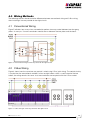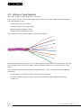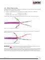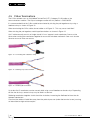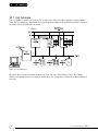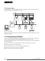
1
C-Bus® Basic
Training Manual
Volume 1
1A. Introduction to C-Bus
1B. C-Bus Concepts
1C. C-Bus Hardware
Revision Number: V2
®
© Copyright Clipsal Australia Pty Ltd 2007. All
rights reserved. This material is copyright under
Australian and international laws. Except as
permitted under the relevant law, no part of this
work may be reproduced by any process without
prior written permission of and acknowledgement
to Clipsal Australia Pty Ltd.
Clipsal is a registered trademark of Clipsal
Australia Pty Ltd.
The information in this manual is provided in
good faith. Whilst Clipsal Australia Pty Ltd (CAPL)
has endeavoured to ensure the relevance and
accuracy of the information, it assumes no
responsibility for any loss incurred as a result
of its use. CAPL does not warrant that the
information is fit for any particular purpose, nor
does it endorse its use in applications which are
critical to the health or life of any human being.
CAPL reserves the right to update the information
at any time without notice.
V 2 November 2007
2
C-BUS TRAINING MANUAL - VOL 1
Contents Volume 1A. Introduction to C-Bus
Scope
7
Learning Outcomes
7
Introduction – What is C-Bus?
8
1.0
Why Use C-Bus?
9
1.1 Ease Of Wiring
10
1.2 Flexibility
10
How C-Bus Works
10
2.0
2.1 C-Bus Network Wiring
10
2.2 C-Bus Units
11
2.3 Simple Control
11
2.4 Multiple Events
11
2.5 Control Flexibility
11
2.6 Types of Units
12
System Support Devices
12
Input Units
12
Output Units
12
3.0
C-Bus Communications
13
4.0
Wiring Methods
15
4.1 Conventional Wiring
15
4.2 C-Bus Wiring
15
4.3 Wiring a C-Bus Network
16
4.4 Which Wires to Use
17
4.5 C-Bus Terminations
18
4.6 Standard Network Topology
19
4.7 Location of C-Bus Units
20
5.0
Mains and C-Bus Segregation
21
6.0
C-Bus Power Supplies
22
6.1 Voltage and Electrical Characteristics
22
6.2 Short Circuit and Overload Protection
22
6.3 Over Voltage Protection
22
6.4 Multiple Power Supplies
22
6.5 Types of Power Supplies
23
7.0
Network Burdens
23
8.0
C-Bus Operating Parameters
24
9.0
C-Bus Multi Network Installations
25
9.1 Maximum Number of Networks
1A. Introduction to C-Bus
25
3
Contents Volume 1A. Introduction to C-Bus
10.0
Address Structure
27
10.1 Unit Address
28
10.2 Group Address
29
10.3 Area Address
30
11.0
Programming Technique
30
12.0
C-Bus Tools and Functions
31
12.1 Local Toggle Buttons
31
12.2 C-Bus Network Analyser 5000NA
31
12.3 Learn Mode
31
Contents Volume 1B. C-Bus Concepts
Scope
33
Learning Outcomes
33
1.0
C-Bus Network Specifications
33
1.1 Cable Type
33
1.2 Maximum Cable Length
35
1.3 Mains Segregation
36
1.4 Single Network Topology
37
1.5 C-Bus Cable Current
38
1.6 System Voltage
38
1.7 Units per Network
38
1.8 C-Bus Clock
39
1.9 Network Burden
40
2.0
C-Bus Addressing Conventions
41
2.1 Network Address
41
2.2 Unit Address
41
2.3 Application Address
42
2.4 Group Address
43
2.5 Area Address
43
2.6 Levels and Selectors
43
2.7 C-Bus Tags
44
4
C-BUS TRAINING MANUAL - VOL 1
Contents Volume 1C. C-Bus Hardware
Scope
46
Learning Outcomes
46
1.0
System Support Devices
46
1.1 Power Supply
47
1.2 Network Bridge
48
1.3 PC Interface
50
2.0
C-Bus Input Units
51
2.1 Operation of Input Units
52
2.2 Pressing a Button
52
2.3 Sending Input Messages
53
3.0
C-Bus Output Units
53
3.1 Voltage Free Relay
54
3.2 Voltage Free Changeover Relay
54
3.3 Professional Series Dimmer
55
3.4 DIN Rail Series Dimmer
55
3.5 DSI Gateway
55
3.6 Analogue Output Unit
56
3.7 Infrared Transmitter
56
4.0
C-Bus Indicators
57
Index
62
1A. Introduction to C-Bus
5
Volume 1A
Introduction to C-Bus
6
C-BUS TRAINING MANUAL - VOL 1
Scope
This manual provides an installer with basic skills needed to program and use C-Bus. A fundamental
technical background is required.
The manual includes:
• an overview of C-Bus
• C-Bus wiring methods
• C-Bus terminations
• C-Bus power supplies
• network burdens
• operating parameters
• multiple networks
• C-Bus addressing concepts.
It is an ideal preparation before attending the C-Bus Basic Training Course.
Learning Outcomes
By the end of this module, you should have an understanding of:
• how C-Bus works
• C-Bus wiring
• characteristics of a C-Bus power supply
• using a Network Burden
• connecting multiple network C-Bus projects
• various C-Bus addresses
• various operating parameters.
1A. Introduction to C-Bus
7
Introduction - What is C-Bus?
C-Bus is a microprocessor-based control and management system for buildings and homes. It is
used to control lighting and other electrical services such as pumps, audiovisual devices, motors,
etc. Whether it’s simple ON/OFF control of a lighting circuit, or variable (analogue) type control, such
as electronic dimmable fluorescent ballasts, C-Bus can be used to easily control virtually any type of
electrical load.
To ensure fast and reliable operation, each C-Bus device has its own in-built microprocessor and
“intelligence”, allowing units to be individually programmed.
C-Bus uses a patented method for updating the status of units. This method does not require a
central computer or central controller to handle databases or look-up tables to operate. The status
of each C-Bus unit is initiated at specific time intervals, without the need of a central controller. Each
device is allocated a specific time frame to broadcast its status, synchronised by a self-generated
system clock pulse. This allows large amounts of data to be transmitted in a very small time frame,
effectively and reliably on the network, leading to low processing overheads and low bandwidth
requirements.
8
C-BUS TRAINING MANUAL - VOL 1
1.0 Why Use C-Bus
There are many reasons to use C-Bus:
• it is a highly robust and reliable control system, with a low cost per node
• a wide range of tools is available, allowing third party companies to interface with both PC based
and embedded systems
• a single C-Bus cable connection can control many devices
• C-Bus offers the ultimate flexibility in switching and control. Functions can be changed, added,
removed, moved, reprogrammed, at any position on the network, at any time – without any
cumbersome hard-wiring
• C-Bus is simple to install and commission
• C-Bus can control any type of load, digital and analogue.
Electrical wiring practices have not changed much since the introduction of insulated multicore
cabling. However, wiring requirements in commercial buildings have changed rapidly since that
innovation. The additions of fire and smoke detection, security and energy management systems have
placed high demands on electrical installations.
The need for central monitoring and control of these extra systems may result in massive networks of
wires emanating from the control area.
Conventional wiring practice requires current to flow through both a switch and its load. This requires
heavy conductors to run from the switchboard to the load and from the load to the controlling
switches. These aspects add to wiring complexity, increasing installation time, documentation control
and overall system cost. Maintenance and system flexibility can be problematic.
The C-Bus network overcomes these problems. It uses a twisted pair of wires such as Unshielded
Twisted Pair (UTP) Category 5 (Cat-5) Local Area Network (LAN) cable, to communicate between
a building’s light switches and load controlling devices. This same cable pair also provides the d.c.
supply voltage to the C-Bus devices.
This greatly reduces the number of heavy wires in an installation, while enabling easy central
monitoring and system control.
C-Bus can be expanded to control and monitor a building’s electrical appliances from a personal
computer. Security, air conditioning and other systems can be programmed to turn on or off at
specific times or events. Lighting and temperature can be varied according to ambient conditions.
Inputs, switches and loads can be reconfigured without reconnecting a single wire.
1A. Introduction to C-Bus
9
1.1 Ease Of Wiring
No point to point wiring is required. All input and output units are looped together with Cat-5 UTP
cable. Units do not need to be wired in any particular order.
The positive and negative C-Bus terminals on each unit are connected to the appropriate conductors
on the C-Bus cable. These two conductors carry a low voltage power supply for the electronics in
each C-Bus unit, and also allows digital control signals to be sent between units.
1.2 Flexibility
A C-Bus input unit can be programmed to perform various functions such as timing, dimming on/off
and other functions. This programming can be changed as often as needed.
An input can control many outputs, providing simple load bank control. An output can be controlled
by many inputs, providing multipoint control (including dimming) without complex wiring.
The program that specifies which inputs control and which outputs can be changed as often as
needed, to match an installation’s changing needs.
2.0 How C-Bus Works
2.1 C-Bus Network Wiring
The C-Bus network bus is the communications wiring for the system, consisting of an unshielded
twisted pair (UTP) Cat-5 cable. The bus not only provides the means of communication between
units, but also the small amount of power needed to operate the circuitry within each C-Bus unit.
The C-Bus network is electrically isolated from the mains power, and operates at safe extra low
voltage level (36V d.c.). Legal restrictions of mains wiring do not apply, so C-Bus wiring may be run
into places that would be dangerous (or illegal) with normal mains wiring.
All input and output devices are wired to any point in the C-Bus network by a twisted pair cable,
which carries all communications between the units.
The C-Bus connections may be looped from unit to unit or a branch can be made at any point. This
‘free topology’ structure provides a flexible system layout. New units can be added anywhere, at any
time, without reconfiguration.
During commissioning, the system is programmed so that specific commands trigger specific
responses in one (or more) devices on the network. At any time the commands can be reprogrammed, and C-Bus units can also be added, removed or moved.
The size of a C-Bus network is practically unlimited. A large network is usually divided into subnetworks of 100 C-Bus units, with a total cable length of 1 km per sub-network. This allows a C-Bus
system to be divided into manageable sections, simplifying design, limiting potential fault propagation
and aiding in any troubleshooting.
10
C-BUS TRAINING MANUAL - VOL 1
2.2 C-Bus Units
All units on the C-Bus network have their own built-in microprocessor, allowing them to operate
independently with “distributed intelligence”. This provides extremely reliable and efficient
communications.
Every C-Bus unit has a unique number, so that all devices on the network can communicate directly.
Also, as C-Bus uses point to multi-point communication, every device on a C-Bus network issues
and responds to commands directly from the network, rather than requiring a central computer or
controller.
2.3 Simple Control
Each C-Bus device is programmed to issue and respond to the certain commands. A virtually
unlimited number of commands can be programmed into the C-Bus system. Generally, input
devices are programmed to issue commands, and output devices are programmed to execute those
commands.
When a C-Bus Group Address command is issued by a C-Bus device, any other devices that have
been programmed with that Group Address will be activated, wherever they are on the C-Bus
network. There is no need for any direct 240 V connection between any C-Bus units.
2.4 Multiple Events
Single devices can also produce multiple events. For example, you may program an input switch so
that the length of time the key is pressed determines what Command is issued – a short press issues
an on/off command and a long press controls a dimming command.
Multiple commands do not have to control the same output device(s), so complex scenarios can be
easily created, for example a single push button switch controlling a whole floor of a building.
Multiple input devices can conditionally control a single output device, dependant on specific
circumstances. This allows multiple levels of over-ride switching and other complex control systems to
be created easily.
2.5 Control Flexibility
The C-Bus system can carry out control in virtually unlimited ways:
• any input device can be programmed as a master control point. Master overrides can be
positioned anywhere in the network, and control any other unit or units on any connected
network
• the system can allow unlimited switching configurations. Two, three (or more) switches can be
set to toggle or control any other switch or device
• overrides can be easily re-programmed via Windows software at any time
• a computer or central controller is not required for normal C-Bus operation, but can be used to
add additional features if desired.
1A. Introduction to C-Bus
11
2.6 Types of Units
There are 3 main categories of C-BUS devices.
2.6.1 System Support Devices
• Power Supply
• Network Bridge
• PC Interface
• Computer Network Interface (CNI) Unit.
2.6.2 Input Units
• Switch Plates (1, 2, 4, 6, 8, 12, 16, 20 or 24 button)
• Light Level Sensors
• PIR Occupancy Sensors
• Temperature Sensors
• Real Time Clocks
• Auxiliary Input Units
• Infrared Receivers
• Scene Controllers
• Bus Coupler
• Thermostat.
2.6.3 Output Units
• Voltage Free Relays
• Voltage Free Changeover relays
• Dimmers
• DSI Gateway
• Analogue Output (0 – 10V DC)
• Infrared Transmitters.
12
C-BUS TRAINING MANUAL - VOL 1
3.0 C-Bus Communications
When a button is pressed on an input unit, a measurement is made of its press duration. This
measurement influences the message that the unit issues in response to the button press (depending
on its programming). This is illustrated in Figure 1.
Figure 1 – An input unit measures the duration of a button press before responding
The relevant C-Bus message is then transmitted over the C-Bus network as indicated by the dashed
line in Figure 2.
Figure 2 – An input unit transmits a message over the C-Bus network
1A. Introduction to C-Bus
13
The C-Bus message is broadcast over the bus for all C-Bus units to read, as illustrated in Figure 3. It
contains information about the Group Address and the operation to be performed, such as switch on
or off. Only the C-Bus units with the same address will respond.
Figure 3 – A C-Bus message is read by all C-Bus units connected to the same network
Once the C-Bus units have received and interpreted the message, they respond according to their
programming, switching the appropriate load (Figure 4).
Figure 4 – A C-Bus output unit switches its loads in response to a message sent by an input unit
14
C-BUS TRAINING MANUAL - VOL 1
4.0 Wiring Methods
The following sections demonstrate the difference between conventional wiring and C-Bus wiring,
when installing a two-way control for four light circuits.
4.1 Conventional Wiring
Figure 5 indicates how many wires are needed to perform two-way control between two four-gang
plates. As many as 13 mains conductors need to be run between the two plates and the loads.
Figure 5 – Conventional wiring of a two-way control for four light circuits
4.2 C-Bus Wiring
Figure 6 shows how the same two-way control is wired using C-Bus (pink wiring). The control circuitry
is simpler than the conventional method. If a four or eight button switch is used instead of the two
button, the wiring remains the same. Just two conductors are required to link the C-Bus control.
Figure 6 – C-Bus wiring of a two-way control for four light circuits
1A. Introduction to C-Bus
15
4.3 Wiring a C-Bus Network
The C-Bus system is wired using Cat-5 UTP cable.
C-Bus Cat-5 UTP has a mains rated sheath (pink) and consists of four colour-coded twisted pairs.
The standard colours are:
• blue twisted with blue & white
• orange twisted with orange & white
• green twisted with green & white
• brown twisted with brown & white.
The conductors within a C-Bus cable are displayed in Figure 7.
Figure 7 – Conductors within a C-Bus cable
The electrical characteristics of Cat-5 UTP cable include low resistance and capacitance. The cable
also has high noise immunity (provided by the twist between the pairs), making it ideal for C-Bus
wiring.
Two conductors are used for each positive connection to a C-Bus unit and two for each negative
connection:
• a termination is more secure when made with two conductors
• the extra copper provided by the second conductor reduces the voltage drop on long
cable runs.
16
C-BUS TRAINING MANUAL - VOL 1
4.4 Which Wires to Use
In order to maintain noise immunity, the natural twist between pairs must be retained when connecting
to the positive and negative C-Bus terminals.
It is important that the following Cat-5 conductors are used when making C-Bus connections:
• orange + blue
for positive C-Bus Wires
• orange & white + blue & white for negative C-Bus Wires.
Figure 8 shows correct wiring that maintains the natural twist of the C-Bus cable conductor pairs.
Figure 8 – Correct pairing of C-Bus conductors
Figure 9 shows incorrect pairing of conductors. This increases the C-Bus network’s susceptibility to
electrical interference.
Figure 9 – Incorrect pairing of C-Bus conductors
IMPORTANT Using the correct pairing while maintaining the cable twist (Figure 8) provides
increased immunity to electromagnetic interference.
CIS have standardised on using the orange conductor and blue conductor for the positive connection,
and the orange & white conductor and the blue & white conductor for the negative connection. This
colour code matches that used in Cat-5 patch cords supplied with the C-Bus DIN range of products.
1A. Introduction to C-Bus
17
4.5 C-Bus Terminations
The C-Bus network uses an Unshielded Twisted Pair (UTP), Category 5 LAN cable as the
communications medium. The Clipsal catalogue number for this product is 5005C305B.
It is recommended that the C-Bus cable be terminated by twisting the pair together or by using a
bootlace crimp as shown in Figure 10.
When terminating the C Bus cable, do not solder as in Figure 11. This may cause “cold flow”.
When twisting the pair together, avoid frayed terminations as shown in Figure 12.
Cat-5 cable normally consists of single strand 0.2 mm² copper in each conductor. Care must be
taken when twisting the conductors together to ensure the wire does not break. Care must also be
taken to ensure all wires are secure.
Figure 10 – Terminating with a bootlace crimp
Figure 11 – Soldering may cause cold flow
Figure 12 – Avoid frayed terminations
Up to four Cat-5 conductors can be securely held using a small bootlace or ferrule crimp. Depending
on the size of crimp, several crimps may be held in a terminal.
Soldering conductors together shrinks back the insulation, increasing the likelihood of short circuits
between conductors.
Over time the solder will cold flow away from the point of pressure (under the terminal screw), causing
an intermittent or high resistance joint.
18
C-BUS TRAINING MANUAL - VOL 1
The Clipsal C-Bus data cable is strongly recommended due to its distinctive pink outer sheathing.
This reduces confusion between a C-Bus network and information systems (such as data, fire and
telephone), at the same installation. The Cat-5 UTP also has a 240V mains rated outer sheath. This is
a requirement where the cable enters a switchboard, and is present in the same enclosure as single
insulated mains wire.
The RJ45 end is an 8-position modular connector that looks like a large phone plug. There are
a couple variations available. The primary variation you need to pay attention to is whether the
connector is intended for braided or solid wire. For braided/stranded wires, the connector has
contacts that actually pierce the wire. For solid wires, the connector has fingers, which pierce the
insulation and make contact with the wire by grasping it from both sides. The connector is the weak
point in an ethernet cable, choosing the wrong one will often cause grief later. If you just walk into a
computer store, it’s pretty impossible to tell what type of connector it is, if it isn’t specifically labelled.
Strain relief boots are somewhat helpful sometimes.
The C-Bus connectors are wired as a standard patch lead, as shown in Table 1.
Pin Connection
Colour
1
Remote Override ON
Green & white
2
Remote Override ON
Green
3
C-Bus Negative (-)
Orange & white
4
C-Bus Positive (+)
Blue
5
C-Bus Negative (-)
Blue & white
6
C-Bus Positive (+)
Orange
7
Remote Override OFF
Brown & white
8
Remote Override OFF
Brown
RJ45 pictured with clip facing down.
Table 1 – C-Bus connector identification
4.6 Standard Network Topology
C-Bus units can be wired together in a number of different ways. They can be “daisy chained”
together. This uses the least amount of cable but may cause excessive voltage drop over long runs.
(Spreading C-Bus power supplies or output units with in-built power supplies around the network, will
address this).
Alternatively C-Bus units can be “star wired” back to a central point, such as a switchboard where the
output units are mounted. This limits voltage drop but may use more cable.
In most cases the most suitable topology is a combination of daisy chain runs, which are star wired
out from output unit locations.
Ring topologies are not recommended. While they offer some redundancy in case of broken or
damaged wires, ring topologies can provide parallel communication runs that may result in distorted
waveforms and “race” conditions.
A calculator tool and information regarding voltage drop across networks is available at
1A. Introduction to C-Bus
19
4.7 Location of C-Bus Units
It is important to choose a suitable location to mount a C-Bus unit. Input units are typically located in
a position convenient for the people who will operate them. DIN Rail output units are typically installed
inside a power distribution board or cabinet.
Some important factors to consider:
• ensure the mounted unit will not be subject to high temperatures. Most C-Bus units are rated
to operate at an ambient temperature of up to 45 °C. When mounted in a confined space (such
as a cabinet), the units contribute to the ambient temperature. This is particularly true of dimmer
units, which dissipate more heat than other unit types. Avoid mounting in places that may
become hot such as ceiling cavities or in direct sunlight
• choose a location that will not become wet or subjected to extreme humidity
• ensure units are mounted at a suitable height for the end user
• consult the unit’s Installation Instructions as there may be specific mounting considerations for a
particular unit type.
20
C-BUS TRAINING MANUAL - VOL 1
5.0 Mains and C-Bus Segregation
With all C-Bus units that have mains as well as 36V d.c. bus connections, care must be taken to
adequately separate the 240Va.c. wiring from the bus wiring. Pink C-Bus Cat-5 UTP, with its mains
rated outer sheath, must be used within the confines of a switchboard.
Wiring practices vary from installer to installer. Sometimes the mains cable entering the switchboard
is double insulated, while other times it is single insulated. When it is double insulated, the outer
insulation must be stripped back to allow the connection of mains wires to the DIN unit power supply
and output terminals.
No isolation issues can be expected between C-Bus and a single insulated mains cable, when the
pink C-Bus Cat-5 cable enters a switchboard and plugs straight into a DIN module.
The 300 mm pink Cat-5 patch leads supplied with all DIN units are used to loop in and out of any
other DIN units within the enclosure.
Where more than one pink Cat-5 cable enters the switchboard, care must be taken to ensure that any
join made between multiple Cat-5 cables is effectively insulated with no exposed terminal screws etc.
Consider terminating multiple C-Bus Cat-5 cables outside the switchboard, and bringing just one into
the RJ socket on a DIN unit.
The mains rated pink sheath allows the C-Bus Cat-5 cable to run closer to mains wiring than would
otherwise be allowed. To give the greatest margin of noise immunity within the switchboard and
overall installation:
• always maintain 150 mm of separation between C-Bus and mains cable, when running C-Bus
cable in parallel with mains
• ensure that C-Bus always crosses mains cable at a 90 degree angle, with at least 60 mm of
separation.
Most importantly, securely anchor both Cat-5 and mains cable in switchboards. This provides an
additional safety margin against contact between loose mains conductors, and the C-Bus
36Vd.c. wiring.
IMPORTANT
NOTE
1A. Introduction to C-Bus
Wiring regulations covers these issues. An installer must ensure that wiring is
carried out in a safe manner. The safety and protection of users of equipment
is of the highest importance. The product warranty will be affected if a failure is
found to be caused by poor wiring practice. In addition, the isolation between
mains and C-Bus wiring is one of the key checks made during a CIS Approved
Installer* visit.
*An Approved Installer is a person or company that has had the standard
of their installation, servicing abilities and quality of service to customers
recognised by Clipsal Integrated Systems. This recognition is secured through
on going training, on site assessments and customer feedback.
21
6.0 C-Bus Power Supplies
The two-wire connection between C-Bus units serves two purposes. It is the communication medium
through which on and off signals are sent between inputs and outputs. It also carries a 36Vd.c. supply
to power the electronics in C-Bus units.
6.1 Voltage and Electrical Characteristics
The C-Bus power supply is isolated from the mains supply by at least 3kV. It achieves this isolation
using a double wound transformer. The output voltage is capped at 36V. C-Bus units that connect to
both mains and C-Bus supplies use transformers or opto-isolators to achieve isolation.
To achieve successful communication across the bus, power supplies must have the correct electrical
characteristics. For this reason only C-Bus power supplies are suitable for use in a C-Bus installation.
6.2 Short Circuit and Overload Protection
The internal circuitry of the power supply will react if:
• the bus conductors are shorted together
• too many C-Bus units are connected to a supply
• a C-Bus unit is incorrectly connected.
In all cases the power supply will limit the amount of current that flows to a safe level, ensuring that
neither it nor any other C-Bus unit is damaged.
6.3 Over Voltage Protection
It is recommended that sufficient over voltage and lightning protection be fitted, particularly in areas
where there is a high incidence of lightning strikes. The Clipsal 970 Series may be useful for this
purpose.
6.4 Multiple Power Supplies
Where the number of C-Bus units used on a system exceeds the capability of a C-Bus power
supply, additional power supplies are connected to increase capacity. In larger installations the
power supplies are best distributed around the system, to minimise voltage drop across the C-Bus
conductors. On any one C-Bus network, the combined power from the power supplies should not
exceed 2A, as this would exceed the current handling capability of the Cat-5 cable.
22
C-BUS TRAINING MANUAL - VOL 1
6.5 Types of Power Supplies
C-Bus power supplies are available in a number of configurations. These include stand-alone units,
and supplies incorporated into relay or dimmer output units. Table 2 lists the output currents of various
power supply types.
Type of Power Supply
Output Current
DIN rail stand-alone
350mA
DIN rail on-board
200mA
Pro Series Dimmer on-board*
60mA
Matrix Switcher
330mA
Table 2 – Power supply output currents
NOTE *The Twelve Channel Pro Series Dimmer does not come with an on board
C-Bus Power Supply.
The output current specified in an on-board power supply is independent of any power that the unit
uses itself. When calculating the number of units to be powered by an on-board supply, you do not
need to include the unit with the on-board supply in the calculation.
7.0 Network Burdens
A network burden is a 1 kΩ resistor in series with a 10 µF to 22 µF, 50V capacitor. A network burden
acts as an a.c.
filter, and must be connected across each network to ensure reliable communication. Only one
burden should be present
on a C-Bus network.
A network burden has been built-in to particular C-Bus units. Depending on the Unit Address, the
network burden is enabled or disabled using the C-Bus Toolkit software. For a network burden to be
enabled via software, the unit must be at Unit Address 001.
An external hardware network burden can also be used. It is enclosed in an RJ45 package, which can
be plugged into any C-Bus RJ45 socket on the network.
Software burdens can be found on:
• all C-Bus DIN Rail Output Units
• the C-Bus Network Interface
• the PC Interface
• Touch Screens
• the HomeMinder
• General Input Units
• Network Bridges
• Telephone Interfaces.
This list will continue to grow as additional C-Bus units are developed. For more information on a
C-Bus unit, see the installation instructions included with the unit.
1A. Introduction to C-Bus
23
8.0 C-Bus Operating Parameters
The following are important considerations when planning a C-Bus network:
1. The maximum total length of Cat-5 UTP cables on any one C-Bus network is 1 km.
2. The maximum recommended number of C-Bus units on any one network is 100 units. The actual
number is dependent on the impedance and amount of flowing current. The current must not
exceed 2A.
3. Multiple C-Bus power supplies can be connected to a C-Bus network to provide sufficient power
for C-Bus units. The power supplies will share the load evenly. The maximum combined power
supply output for a single network is 2A. Examples of acceptable configurations for a single
network are:
• 6 × 5100PS rated at 350mA each
• 10 × DIN Rail Output Unit on-board power supplies rated at 200mA each
• 30 × Pro Series Dimmer power supplies (except the 12 Channel) rated at 60mA each.
4. Any combination of power supply units is allowed as long as the total power available does not
exceed 2A.
5. Where more than 1 km of cable or 100 standard C-Bus units are required, two or more networks
can be linked using a network bridge.
6. Each C-Bus network requires only one network burden. A burden is contained within:
• all C-Bus output units (such as dimmers and relays)
• most system support devices (such as a PC or network interface)
• some input units (including C-Touch and the Four Channel General Input Unit).
A network burden can also be assembled using a 1kW, 0.6W (or higher) resistor and a 10mF,
50V capacitor in series, connected across the C-Bus 36V rails.
7. Each C-Bus network requires at least one (and a recommended maximum of three) system clock
generating units. A system clock generator is contained within:
• all C-Bus output units (such as dimmers and relays)
• most system support devices (such as a PC or network interface)
• some input units (including C-Touch and the Four Channel General Input Unit).
8. The maximum number of networks that may be combined in a single installation is 255.
9. The maximum number of networks that may be connected in series to the local network is seven
(using six network bridges).
10. C-Bus power supply units (including DIN and Pro units) may be connected to different phases.
11. Individual relay channels may be connected to different phases. On DIN Rail Dimmers, the 240V
supply connected to the units’ power supply and the output channels, must be on the same
phase.
12. The isolation between the 240Va.c. mains and the 36Vd.c. C-Bus circuitry is greater than 3.5kV.
This is achieved using double wound transformers and opto-isolators.
24
C-BUS TRAINING MANUAL - VOL 1
9.0 C-Bus Multi Network Installations
A C-Bus system cannot be expanded past a certain point without the inclusion of a C-Bus Network
Bridge. A bridge splits the installation into separate networks, which are electrically isolated from each
other. It can be programmed to allow communication between networks.
A bridge must be added whenever the current requirement (or the number of units) exceeds the
C-Bus limit, or when the total length of Cat-5 cable exceeds 1 km.
Cross-network communication between units (across a bridge) is determined by programming. It can
be allowed in both directions, in one direction only, or not at all. Regardless of what this is set to, an
operator scanning the network from their PC will be able to see every network connected to a C-Bus
system.
Since a bridge provides electrical isolation between networks (using galvanic separation), power
supplies cannot be shared across this connection. This also means that a separate network burden is
required for each network.
9.1 Maximum Number of Networks
Up to 255 C-Bus networks can be connected using C-Bus Network Bridges. Various topologies can
be employed when connecting the C-Bus networks. There are three types of connection topologies:
• star configuration
• daisy chain configuration
• a combination of star and daisy chain configurations.
An example of a multiple network connected using a star configuration is shown in Figure 13.
Figure 13 – Example of a multiple network connected using a star configuration
1A. Introduction to C-Bus
25
A daisy chain configuration must not exceed six bridges deep. An example of a multiple network
connected using this configuration is shown in Figure 14 .
Figure 14 – Example of a multiple network connected using a daisy chain configuration
Figure 15 shows an example of how a combination of star and daisy chain topologies may be used.
There are hundreds of possible combinations.
Figure 15 – Example of a multiple network connected using a mixed topology configuration
26
C-BUS TRAINING MANUAL - VOL 1
10.0Address Structure
Several types of addresses are used when communicating with C-Bus units. These are described
in Table 3.
Network Address
Identifies each network. Network Addresses range from 000 to 254
(255 is reserved).
Unit Address
Identifies each individual unit on a C-Bus network. Unit Addresses
range from 000 to 254 (255 means undefined).
Application Address
An Application Address is used with a Group Address and Area
Address to define which input(s) will control which output(s). The
default Application Address is “lighting”. The programmer can specify
up to 255 different Applications, but some Application Addresses
have been reserved for specific command types.Using a combination
of Application Address and Group or Area Address gives thousands
of unique combinations.
Group Address
This is used together with an Application Address to provide an
association between C-Bus inputs and outputs. Up to 255 different
Group Addresses may be used on any one Application Address.
Area Address
This is a Group Address entered into a special Area Address field on
a C-Bus output. It is similar in action to the Group Address except
that it can be entered into one or more C-Bus relays and/or C-Bus
dimmers to give master control of all of the channels on those relays
or dimmers.
Level or Selector
This is a value of a Group Address. A Level is most often used to set
a light to a specific level. A Selector is generally used to trigger a
specific scene or select a Schedule. The value of a Level or Selector
ranges from 000 to 255.
Table 3 – Types of addresses used when communicating with C-Bus units
1A. Introduction to C-Bus
27
10.1Unit Address
The Unit Address ranges from 000 to 254. It gives each unit on a C-Bus network a unique identity.
There are 255 addresses available that can be displayed in decimal or hexadecimal format. Figure 16
illustrates how Unit Addresses are used.
240Va.c.
Figure 16 – Unit Addresses
No two C-Bus units on the same network may have the same Unit Address. The C-Bus Toolkit
software will recognise any such conflict, and resolve it by assigning a unique Unit Address to one of
the units.
28
C-BUS TRAINING MANUAL - VOL 1
10.2Group Address
The Group Address determines which button inputs control which output channels. There are 255
addresses available (000 to 254) that can be displayed in decimal, hexadecimal* or text format (Tags)
† . Figure 17 illustrates how Group Addresses are used.
240Va.c.
Figure 17 – Group Addresses (Shown as Tags)
NOTE* Hexadecimal refers to the base-16 number system, which consists of 16
unique symbols - the numbers 0 to 9 and the letters A to F. For example, the
decimal number 15 is represented as F in the hexadecimal
numbering system.
† A C-Bus address can be used in raw numeric form, or it may be assigned a
meaningful name, known as a Tag.
1A. Introduction to C-Bus
29
10.3Area Address
The Area Address is used to simultaneously control all channels on a C-Bus relay or dimmer unit.
Figure 18 illustrates how Area Addresses are used.
240Va.c.
Figure 18 – Area Addresses
Individual relay and dimmer channels can also be controlled from their local toggle buttons (unless
disabled by software).
11.0 Programming Technique
All C-Bus units leave the factory with a default undefined Unit Address value of 255. You need to
assign a unique Unit Address to each unit before connecting it to a C-Bus system.
You do this by programming each unit prior to delivery, using a computer, a 5500PC interface and a
5500PS power supply:
1. ensure the 5500PC has a Unit Address of 000 before connecting the new C-Bus unit
2. connect the C-Bus unit to be programmed
3. assign the Unit Address, as a minimum programming requirement
4. disconnect the unit and mark it with its Unit Address
5. deliver the unit to site and install it on the network.
30
C-BUS TRAINING MANUAL - VOL 1
12.0 C-Bus Tools and Functions
12.1 Local Toggle Buttons
DIN and Pro series C-Bus outputs are equipped with local toggle control for each output channel.
These toggle buttons operate as long as mains voltage is connected to the DIN unit. They do not
require the C-Bus connection to be wired in. Pressing a local toggle control button will alternately
switch the load wired to the respective channel, on and off. This allows you to check that the mains
wiring is correct and that the loads switched by each channel are correct.
12.2 C-Bus Network Analyser 5000NA
This product is temporarily connected to a C-Bus network. It indicates the status of the C-Bus power
supply, network burden, system clock and acceptable cable length.
12.3 Learn Mode
Learn Mode is a method of programming C-Bus units without using software.
See Learn Mode Programming Manual for details.
1A. Introduction to C-Bus
31
Volume 1B
C-Bus Concepts
32
C-BUS TRAINING MANUAL - VOL 1
Scope
This manual aims to provide an installer with the basic skills needed to program and use
C-Bus. A fundamental technical background is required.
This manual covers:
• various C-Bus network specifications
• C-Bus addressing concepts.
It is an ideal preparation before attending the C-Bus Basic Training Course.
Learning Outcomes
By the end of this module, you should have an understanding of:
• various C-Bus cabling requirements
• various single network topology configurations
• various C-Bus network parameters
• differences between the various C-Bus Addresses
• the uses of Tags.
1.0 C-Bus Network Specifications
There are various parameters and characteristics that must be followed in order for the C-Bus
network to function reliably.
1.1 Cable Type
The C-Bus network uses an Unshielded Twisted Pair (UTP) Category 5 (Cat-5) Local Area Network
(LAN) cable, as the communication medium. The Clipsal catalogue number for this product is
5005C305B.
The following conductors of the Cat-5 cable must be used to make the C-Bus connections:
• orange + blue
C-Bus positive
• orange & white + blue & white C-Bus negative.
1B. C-Bus Concepts
33
IMPORTANT Using the above pairing ensures a mutual twist between conductors and C
Bus terminals, providing increased immunity to electromagnetic interference.
It is recommended that the C-Bus cable be terminated by twisting the pair together or by using a
bootlace crimp as shown in Figure 1.
Figure 1 – Terminating with a bootlace crimp
When terminating the C-Bus cable, do not solder as in Figure 2. This may cause “cold flow”.
Figure 2 – Soldering may cause cold flow
When twisting the pair together, avoid frayed terminations as shown in Figure 3.
Figure 3 – Avoid frayed terminations
The Clipsal C-Bus data cable is strongly recommended due to its distinctive pink outer sheathing.
This reduces confusion between a C-Bus network and information systems (such as data, fire and
telephone), at the same installation. The Cat-5 UTP also has a 240 V mains rated outer sheath. This
is a requirement where the cable enters a switchboard, and is present in the same enclosure as single
insulated mains wire.
The C-Bus connectors are wired as a standard patch lead, as shown in Table 1
34
C-BUS TRAINING MANUAL - VOL 1
1.2 Maximum Cable Length
On any given C-Bus network, the total length of Cat-5 UTP cable used must not exceed 1 km.
This figure is determined by the propagation delay of C-Bus communication at a total cable
capacitance of 100nF.
Large cable lengths can introduce undesirable effects on the network such as:
• a drop in voltage
• an increase in cable capacitance.
A voltage drop will occur because the Cat-5 cable has a resistance of 90Ω per kilometre. To minimise
the amount of voltage drop along a large length of cable, evenly space the C-Bus power supplies
along the C-Bus Network.
Using a large amount of Cat-5 cable will result in a high capacitance, causing the C-Bus
clock to distort.
1B. C-Bus Concepts
35
1.3 Mains Segregation
With all C-Bus units that have mains as well as 36Vd.c. bus connections, care must be taken to
adequately separate the 240Va.c. wiring from the bus wiring. Pink C-Bus Cat-5 UTP, with its mains
rated outer sheath, must be used within the confines of a switchboard.
Wiring practices vary from installer to installer. Sometimes the mains cable entering the switchboard
is double insulated, while other times it is single insulated. When it is double insulated, the outer
insulation must be stripped back to allow the connection of mains wires to the DIN unit power supply
and output terminals.
No isolation issues can be expected between C-Bus and a single insulated mains cable, when the
pink C-Bus Cat-5 cable enters a switchboard and plugs straight into a DIN module.
The 300 mm pink Cat-5 patch leads supplied with all DIN units are used to loop in and out of any
other DIN units within the enclosure.
Where more than one pink Cat-5 cable enters the switchboard, care must be taken to ensure that any
join made between multiple Cat-5 cables, is effectively insulated with no exposed terminal screws etc.
Consider terminating multiple C-Bus Cat-5 cables outside the switchboard, and bringing just one into
the RJ socket on a DIN unit.
The mains rated pink sheath allows the C-Bus Cat-5 cable to run closer to mains wiring than would
otherwise be allowed. To give the greatest margin of noise immunity within the switchboard and
overall installation:
• always maintain 150 mm of separation between C-Bus and mains cable, when running C-Bus
cable in parallel with mains
• ensure that C-Bus always crosses mains cable at a 90 degree angle, with at least 60 mm of
separation.
Most importantly, securely anchor both Cat-5 and mains cable in switchboards. This provides
an additional safety margin against contact between loose mains conductors, and the C-Bus
36Vd.c. wiring.
IMPORTANTThese issues are covered by wiring regulations. An installer must ensure that
wiring is carried out in a safe manner. The safety and protection of users of
equipment is of the highest importance. The product warranty will be affected if
a failure is found to be caused by poor wiring practice. In addition, the isolation
between mains and C-Bus wiring is one of the key checks made during a CIS
Approved Installer visit.
36
C-BUS TRAINING MANUAL - VOL 1
1.4 Single Network Topology
All C-Bus units may be wired in star, daisy chain or a combination of both configurations. A closed
ring configuration must not be used. Wiring the C-Bus network in this configuration will cause erratic
behaviour.
Daisy Chain
The daisy chain wiring configuration (shown in Figure 4), is basically a run of units, connected with its
positive and negative terminals in parallel.
Figure 4 – A daisy chain configuration
Star
Figure 5 shows some input units wired in a star configuration. This is basically a run of units,
connected with multiple wires coming into the positive and negative terminals in parallel.
If two or more cable runs branch off from a single point, it is referred to as a star configuration.
Figure 5 – A star configuration
1B. C-Bus Concepts
37
1.5 C-Bus Cable Current
The maximum amount of current allowed to flow on Cat-5 UTP cable is 2A. This is a limitation of the
cable. If 2 A is exceeded, you run the risk of damaging the C-Bus cable.
1.6 System Voltage
At all points in a C-Bus network, the voltage across a C-Bus unit must be within the range of 15V to
36Vd.c. However, a C-Bus voltage as low as 15Vd.c., may cause unstable communication. As a rule
of thumb, it is strongly recommended that the C-Bus voltage be maintained at 20Vd.c. or higher.
IMPORTANTWithin an individual network, try to evenly distribute C-Bus power supplies
along the network. This will ensure a minimal voltage drop over the
C-Bus cable.
1.7 Units per Network
Two factors determine how many units can be put onto a C-Bus Network. These are:
• network impedance
• current consumption.
To calculate the maximum number of C-Bus units allowed on a network, add the current consumption
of all the inputs, system support units and outputs that do not have power supplies. The combined
current consumption of all these devices must not exceed 2A.
Note: The C-Bus Toolkit software will also calculate this for you.
38
C-BUS TRAINING MANUAL - VOL 1
1.8 C-Bus Clock
At least one clock must be enabled on the C-Bus Network. In the absence of a C-Bus clock, no
communication will be transmitted along C-Bus.
Note: This is not a real time clock, but a means by which communication is
synchronised.
There will only ever be one active clock on the C-Bus network, however it is recommended to have
multiple system clock generating units available for a redundant system. If multiple system clock
generators are available (enabled), the network will determine which unit will have the active clock.
IMPORTANTWhere possible, avoid enabling a C-Bus clock on a network bridge or network
interface.
Figure 6 shows a single C-Bus Clock pulse viewed through a Cathode Ray Oscilloscope.
Figure 6 – A single C-Bus clock pulse viewed through a Cathode Ray Oscilloscope
1B. C-Bus Concepts
39
1.9 Network Burden
A network burden applies a standard impedance to a C-Bus network. It consists of a 1kW, 0.6W
resistor in series with a 10 to 22µF, 50V capacitor as shown below.
10uF - 22uF
50V
1kW 0.6W
Figure 7 – A network burden
There are two ways in which a network burden may be added
• via hardware
• via software (by enabling a unit’s in-built burden).
A network burden should only be used to adjust the network impedance to between 400W
and 1.5 kW.
A hardware burden is enclosed in an RJ45 package, which can easily be added or removed from a
C-Bus socket. The software burden is enabled or disabled using C-Bus Toolkit software.
40
C-BUS TRAINING MANUAL - VOL 1
2.0 C-Bus Addressing Conventions
Several types of addresses are used when communicating with C-Bus units.
2.1 Network Address
A C-Bus network is a collection of C-Bus devices connected together using Cat-5 UTP LAN cable.
The network size is dependent on various factors such as:
• the Cat-5 cable length
• the number of units per network
• the total current drawn on the Cat-5 cable.
The Network Address is a code assigned to each network within a particular project. A Network
Address can be any value between 000 and 254. A C-Bus network defaults to a Network
Address of 254.
Network Addresses are really only of concern when multiple networks are used.
2.2 Unit Address
All units on a C-Bus network have a unique identity code called a Unit Address. This code is used in
messages sent over the bus, to ensure that only the appropriate unit responds. Such messages are
typically used to program C-Bus operating variables.
The unique Unit Address allows:
• each unit to be individually programmed and customised, without removing it from the network
• instructional messages to be passed over the network to specific units.
A Unit Address ranges from 000 to 255, however 255 is reserved as a default for new units which
have not been assigned a unique Unit Address.
1B. C-Bus Concepts
41
2.3 Application Address
An Application Address is used together with a Group or Area Address to identify one or more units,
inputs or outputs. It provides a convenient way to separate units and their associations, into different
categories. The default Application Address is “lighting”. The programmer can specify up to 255
Application Addresses.
Using two address types provides thousands of unique Group Address combinations, instead of
the 255 which would be available if only a single Application Address was used. This means that a
message to switch an output within the lighting application, will not affect an output within the heating
application, even if both outputs used the same Group Address.
It is recommended that specific Application Addresses are used for particular applications. (Special
features may be associated with these Application Addresses in the future). These are listed in Table
2. Other Application Addresses may be used for different applications.
Application
Application Address
Free use for developers
000 to 015 (00h to 0Fh)
Temperature Broadcast
025 (19h)
Room Control System (Clipsal 5 Star)
038 (26h)
Lighting
048 to 094 (30h to 5Eh)default is 056 (38h)
Dali Gateway Interface Default Application
095 (5Fh)
Ventilation (dampers and fans)
112 (70h)
Irrigation control
113 (71h)
Pool, spa, fountain and pond control
114 (72h)
Heating
136 (88h)
Trigger control
202 (CAh)
Enable control
203 (CBh)
Audio / Visual
205 (CDh)
Security
208 (D0h)
Metering (gas, water, electricity, oil, etc)
209 (D1h)
Clock and Timekeeping
223 (DFh)
Telephony Status and Control
224 (E0h)
Measurement (light, liquid, temperature, etc)
228 (E4h)
C-Bus Network Management and Control
255 (FFh)
Table 2 –Application Address assignments
42
C-BUS TRAINING MANUAL - VOL 1
2.4 Group Address
Within any application, Group Addresses are used to communicate between all units on the C-Bus
network. The C-Bus addressing scheme allows you to define up to 255 different groups per
application. Using Group Addresses to communicate between input and output units, it is possible to
emulate or expand beyond the functionality of conventional wiring.
Messages broadcast by an input device will be seen by the entire network, but only the units with a
corresponding Group Address will react.
By assigning a common Group Address to several units, a number of loads can be controlled by a
single button press on a wall switch. In the same way, a number of wall switches can control the same
load, by assigning a common Group Address.
2.5 Area Address
An Area Address controls an entire C-Bus unit. It is a variation of a Group Address and can be
programmed into the “Area Address” field on most C-Bus units. This gives the ability to control all
channels on an output unit via one group address. If it is programmed to an input unit, it allows for all
indicator LED’s on the input unit to update quicker than the standard 3 second SR interval. If the input
unit has buttons programmed as timers, the timers will also be reset.
A common Area Address may be assigned to multiple output units. Up to 255 Area Addresses may
be used (000 to 254), taken from the same address pool as Group Addresses. The default is 255,
which is undefined.
2.6 Levels and Selectors
A Group Address normally uses an additional parameter to provide increased flexibility. This additional
parameter is used for two broad purposes; to select a specific item (to enable or trigger a group), or
to specify a value within a range (such as a lighting level). This additional parameter is referred to as a
Level or Selector (depending on the application it is associated with). It is a value between 000 (0%)
and 255 (100%).
NOTE C-Bus Toolkit sometimes refers to a Level or Selector as a Value or Action
Selector.
Level
A Level is most often used in lighting applications to dim lights to various levels. Lights attached to
relay output units are switched between a Level of 000 (Off) and 255 (On).
Selector
A Selector is used in a trigger control application to trigger a specific scene or action. It is also used in
an enable control application to select a particular Schedule.
A Selector must be set and not ramped to, otherwise it will have no effect. The ramp rate must be set
to zero (an instantaneous change).
1B. C-Bus Concepts
43
2.7 C-Bus Tags
A C-Bus address can be used in raw numeric form, or it may be assigned a meaningful name,
known as a Tag. A Tag is user defined. Table 3 to Table 7 list typical tags you could use for various
address types.
Network Address Tag
Local Network
Remote Network
First Floor
Second Floor
Third Flood
Basement
East Wing
West Wing
North West Wing
Master Bedroom 4 Button
Dining Room C-Touch
Pavilion 4 Button Neo
Garage PIR
Hallway PIR
Fountain Pump Relay
Lighting Apps
Control Application
Enable Application
Trigger Application
Heating Apps
Irrigation
Kitchen Light
Bedroom Light
Bedroom Fan
Pool Pump
Wall Lights
Fan Timer
Welcome Home Scene
Goodnight Scene
Group 1 Level DD
Irrigation Off
Master Off
Scene 1 Trigger
Table 3 – Network Address Tags
Unit Address Tag
Table 4 – Unit Address Tags
Application Address Tag
Table 5 – Application Address Tags
Group Address Tag
Table 6 – Group Address Tags
Level or Selector Tag
Table 7 – Level or Selector Tags
IMPORTANTC-Bus Tags are stored in the C-Bus Toolkit database, but not in physical C-Bus
units. Only numeric addresses are stored in physical C-Bus units. Therefore,
if you do not have the database for an existing project, you will only retrieve
numerical values from a network scan.
44
C-BUS TRAINING MANUAL - VOL 1
Volume 1C
C-Bus Hardware
1C. C-Bus Hardware
45
Scope
This manual provides an overview of various units used in a C-Bus network. A fundamental technical
background is required.
The manual covers:
• system support devices
• input units
• output units
• C-Bus indicators.
It is an ideal preparation before attending the C-Bus Basic Training Course.
Learning Outcomes
By the end of this module, you should have an understanding of:
• system support devices and their uses
• operations for system support devices
• basic calculations used to predict voltage drops over large cable runs
• input units and their uses
• output units and their uses
• recalling operations for the output units by using the manual provided.
1.0 System Support Devices
C-Bus system support devices are units which support the operation of a C-Bus network.
They are used to:
• program C-Bus
• generate C-Bus voltage
• offer multi-network connectivity.
46
C-BUS TRAINING MANUAL - VOL 1
1.1 Power Supply
The C-Bus power supply is a switch mode device, which means it is efficient and compact. It converts
mains voltage into a usable C-Bus voltage of 36Vd.c.. It is the C-Bus power source, providing power
to each unit on the network.
The C-Bus system operates at an Extra Low Voltage (ELV) level. The minimum voltage required by
each device on the bus is 15Vd.c.. However, a voltage this low may cause communication to be
unstable. Therefore, it is strongly recommended that the C-Bus voltage be at least 20Vd.c.
The resistance of a typical C-Bus Unshielded Twisted Pair (UTP) conductor is 90W/km. The typical
current requirement of a C-Bus device is 18mA. Therefore, if one device is connected to the end of
one kilometre of C-Bus cable (Figure 1), the voltage drop would be 90 × 18 × 10–3 or 1.6V.
Figure 1 – Voltage drop over one kilometre of C-Bus cable (Approximately 18 mA per device).
In an installation, power supplies should be distributed evenly along the C-Bus, rather than just at one
end, in order to minimise system voltage drops.
Number of Required Power Supplies
The number of power supplies needed in a C-Bus installation depends upon:
• the power supply output current
• the number and type of devices on the network
• the location of the devices in relation to the power supplies.
While the first two points are easily measured, the third is more subjective. Power supplies should
be placed to minimise voltage drop across the network, reducing power loss. As a general rule, one
power supply is required for every 17 C-Bus units that draw 18mA each.
Output Current Limiting
One of the many advantages of the C-Bus ELV is that connections can be made while power is
applied to the network. (This applies to 36V C-Bus input units, but not units with mains voltage
connections such as dimmers and relays). Should a short circuit occur on the C-Bus, the power
supply current limiting and overload protection feature, provides protection from damage for an
indefinite period of time.
1C. C-Bus Hardware
47
AC Output Impedance
C-Bus messages are voltage pulses which are superimposed over the d.c. power supply voltage. This
requires a high a.c. impedance to be present at communication frequencies. The power supply has a
special output stage that provides this impedance. General purpose off-the-shelf power supplies are
not suitable for C-Bus installations.
1.2 Network Bridge
A network bridge is a special linking unit that allows communication between two or more C-Bus
networks, while maintaining electrical isolation.
A C-Bus network bridge allows:
• relaying of messages between networks, allowing units on multiple networks to be programmed
and monitored from a central location
• transmission of commands which allow input units on one network to control output units on
another. Units across several networks can be assigned the same Group Address to provide this
high level of control.
A C-Bus network bridge has several limitations:
• the Multipoint to Multipoint Interrogation* (MMI) status report cannot be transferred across
a bridge. This means that an input unit controlling an output unit in another network, cannot
automatically correct itself
• a bridge can only send messages to its two adjacent networks plus one other. This limits internetwork control when bridges are used in cascade form
• the maximum number of bridges that can be cascaded is six (in series). A star network topology
is recommended for most installations, and is required to interconnect more than seven
networks.
48
C-BUS TRAINING MANUAL - VOL 1
A network bridge consists of two functionally and electrically independent systems. Each system
consists of a communication interface and microcontroller, powered by the ELV C-Bus power from the
networks to which it is connected.
Each Network Bridge provides optically isolated communication between sub-networks, so the
reliability of the overall system will not be impaired by introducing bridges. Refer to the illustration in
Figure 2
Figure 2 – Construction of a network bridge
NOTE *The Multipoint to Multipoint Interrogation (MMI) Wired C-Bus uses a status
reporting system (known as an MMI), which provides automatic detection and
correction of discrepancies between the states of grouped inputs and outputs.
This status reporting occurs at periodic intervals. Increasing the frequency of
status reporting decreases the response time in which errors are corrected.
However, it increases the amount of network communication traffic. If different
status report values exist in the same network, the smallest value is used. The
default value is 3 seconds.
1C. C-Bus Hardware
49
1.3 PC Interface
A PC Interface provides a communication path between a personal computer and a
C-Bus network (see Figure 2). With a PC Interface and the C-Bus Toolkit software, you can:
• program and issue commands to C-Bus units
• monitor a C-Bus network, logging network activity.
A C-Bus PC Interface can:
• generate a system clock for synchronised data transmissions
• apply a network burden to the C-Bus network.
Figure 2 – A PC interface lets you connect a computer to the C-Bus network
NOTE A C-Bus Network Interface serves the same function as a PC Interface, but
connects to a PC using an Ethernet connection rather than an RS-232.
The C-Bus PC Interface uses a proprietary ASCII command language for
communicating with a PC. Detailed protocol information is available to
approved applicants, from Clipsal Integrated Systems (CIS). Please contact a
CIS representative for more details.
50
C-BUS TRAINING MANUAL - VOL 1
2.0 C-Bus Input Units
C-Bus input units respond to certain stimuli (such as touch, ambient light conditions, temperature and
infrared radiation), by sending messages to appropriate output units in a predetermined way.
There are various types of input unit:
• wall switches (1, 2, 4, 6 or 8 channel), as shown in Figure 3
• light level sensors
• PIR occupancy sensors
• temperature sensors
• real time clocks
• auxiliary input units
• infrared receivers
• scene controllers
• touch screens.
Input units can be used to:
• control lighting conditions manually or as a response to changing light levels
• control air conditioning according to ambient temperature
• respond to human presence by sending commands to security and access systems
• send IR commands to third party devices.
Figure 3 – A DLT wall switch
1C. C-Bus Hardware
51
2.1 Operation of Input Units
Any network needs to have input and output capabilities. Therefore, input units are a fundamental
building block of a C-Bus system.
Input units can only broadcast three types of commands on a C-Bus network. These are:
• on commands
• off commands
• ramp to (level) commands.
When a button is pressed on a wall switch, a message is sent across the C-Bus network for an output
unit to perform one of the three functions above.
An input unit can also perform timing functions. A press of a button starts a timer, and a command
is sent to an associated output unit. After a programmed time interval (of up to 18 hours), another
command is sent to cancel the previous (depending on the unit’s programming).
One of the main features of C-Bus (and the reason the system is so effective), is its self-checking
ability. At regular intervals an input unit issues a request over the network for a status report. In
response to this request, output units with the same Application Address broadcast their status
in the form of an MMI*. This allows inputs assigned to the same Group Address to compare and
synchronise their status. If the comparison disagrees, the input unit may take corrective action. This
corrective action could be as simple as updating its own indicator to match the status of the output,
or issuing a command for the output unit to change its state.
NOTE *MMI (Multipoint to Multipoint Interrogation).
2.2 Pressing a Button
If you press a button on a wall switch, one or more messages may be transmitted over the C-Bus
network. The message transmitted depends on:
• how the unit is programmed
• how long you pressed the button.
A change in ambient lighting, temperature level or the detection of infrared energy may be used
instead of a physical button press, to trigger a response in some input units. Such units include light
level sensors, temperature sensors and PIR occupancy sensors.
52
C-BUS TRAINING MANUAL - VOL 1
2.3 Sending Input Messages
When a C-Bus input or output unit receives a message, it performs a function described in
Table 1. Any internal timers (input units only) on the same Group Address will be forced to cancel.
On A unit’s internal level is set to maximum and its status is set to on.
Off A unit’s internal level is set to zero and its status is set to off.
Ramp To Level A unit’s internal level is set to the level contained in the message. Output
dimmer units ramp to the new level. Two possible status levels exist:
• if the new level is zero, the status is set to off
• if the level in the message is not zero, the status is set to on.
Timer Options
Interval timers reside on input units. When activated, time is decremented in
one second intervals. The maximum timeout range is 18 hours, 12 minutes
and 15 seconds (65,535 seconds). Upon reaching a count of zero, the timer
will send an expiry command message.
Table 1 – Command function types performed in response to a C-Bus message
3.0 C-Bus Output Units
C-Bus output units are used to control external loads. They switch these loads in response to
messages received from associated input units. Output units can be programmed in various ways, to
suit the need of various installations.
There are various types of output unit:
• voltage free relays
• voltage free changeover relays
• Professional Series dimmers
• DIN rail dimmers
• DSI Gateway
• analogue outputs (0 to 10Vd.c.)
• infrared transmitters.
1C. C-Bus Hardware
53
3.1 Voltage Free Relay
The C-Bus 55xRVF Series Voltage Free Relays are relay-switching devices designed to be mounted in
electrical switchboards or similar enclosures (an example is shown in Figure 4). For ease of installation,
they are DIN rail mounted, measuring 12 DIN modules wide.
Several independent voltage free relay contacts are provided for general switching applications. The
series includes units with 10A rated relays for resistive, inductive (lighting loads) or fluorescent loads.
There is also a 20A version.
Units are available with or without a 200mA C-Bus power supply, for powering other C-Bus units
connected to the network.
Figure 4 – A 12 Channel Voltage Free Relay
3.2 Voltage Free Changeover Relay
A C-Bus L5504RVFC Series Voltage Free Changeover Relay is used in an application where
changeover contacts are required. These units are typically used to operate three-speed motors and
two-way motor control devices, such as motorised blinds, shutters, curtains and skylights.
Four independent voltage free, changeover relay contacts are provided, each with normally open,
normally closed and common terminals. They are available with or without an internalC-Bus power
supply. Units with a power supply are capable of supporting other C-Bus units (200 mA capacity).
Voltage free changeover relays are suitable for use with resistive, inductive, fluorescent and
incandescent loads.
54
C-BUS TRAINING MANUAL - VOL 1
3.3 Professional Series Dimmer
The Lx510xDx Professional Series Dimmers are C-Bus output units suitable for dimming resistive and
low voltage loads in lighting applications. Each channel is load rated between 5A and 20A (depending
on the unit’s model).
Housed in an all aluminium heat sink, the dimmers have been designed for fast installation, with
features such as keyhole mounting, front and rear cable access, ample termination space for mains
cabling, and removable terminals for C-Bus and override connections. They have independent
dimmable channels, operating from a single-phase mains voltage. They operate with any mains
frequency in the range 47 to 53Hz or 57 to 63 Hz, and will automatically resynchronise when this
frequency varies.
Professional Series Dimmers draw 18mA from the C-Bus network when not connected to the mains
supply. With mains voltage connected the dimmers provide up to 60mA to the C-Bus network.
3.4 DIN Rail Series Dimmer
The DIN Rail Series Dimmers are C-Bus output units suitable for dimming incandescent and low
voltage lighting. They feature eight leading edge, phase controlled dimming channels. Each channel
has a load rating of between 1 and 2A (depending on the unit’s model).
The dimmers are capable of controlling incandescent and low voltage lighting (utilising iron-core and
electronic transformers, compatible with leading edge dimmers).
Two product variants are available. One incorporates a 200mA C-Bus power supply used to source
current to the C-Bus network. The other is an economical model with the same features and
performance, but does not include the power supply.
3.5 DSI Gateway
A DSI Gateway is a DIN rail mounted C-Bus output device, designed for controlling ATCO-Tridonic
DSI dimming ballasts, or an equivalent product that uses the DSI protocol standard.
DSI Gateway units incorporate eight independent control channels, for switching and dimming
fluorescent luminaries. They are designed to control up to 100 DSI dimming ballasts per channel,
allowing up to 800 electronic ballasts to be connected to one DSI Gateway unit.
The DSI Gateway is capable of detecting faulty lamps connected to its terminals (depending on the
ballast used). When this occurs, the DSI Gateway will shut down the channel, and the corresponding
channel LED indicator flashes at a slower rate (approximately four times per second).
1C. C-Bus Hardware
55
3.6 Analogue Output Unit
The DIN rail mounted Analogue Output Unit provides analogue voltage control signals. These can be
used to drive most types of 0 to 10V electronic dimmable ballasts used in the lighting industry.
The 0 to 10V signal may be used to control other equipment with this standard control input voltage.
The signal direction ranges from 0 to 10V, as the C-Bus ramping level increases from 0% to 100%.
The Analogue Output Unit operates in response to commands from C-Bus input units. The output
terminals can be assigned to any combination of group addresses, providing multiple output control.
Four analogue outputs are provided for independent control of up to four devices, with a common
reference connection.
This unit requires power from a mains a.c supply with Earth.
3.7 Infrared Transmitter
The Infrared Transmitter unit is a C-Bus output unit that controls third party
devices using infrared signals. The unit is typically used to control audiovisual
equipment such as TVs, DVDs and VCRs. Other infrared capable devices
such as motorised blinds and air conditioning units can also be controlled.
A specialised software tool, the C-Bus Infrared Commissioning Application
(CIRCA), is provided for programming the unit. The CIRCA software allows
the user to select infrared codes, and assign C-Bus events to trigger their
transmission. The same configuration can be uploaded to multiple units
without having to be reprogrammed.
A high speed programming cable is required to program this unit.
56
C-BUS TRAINING MANUAL - VOL 1
4.0 C-Bus Indicators
All C-Bus Output Units (apart from the Infrared Transmitter) have three types of indicators that serve a
common purpose. Figure 5 and Table 2 show the location of the indicators on a C-Bus output unit,
together with their explanation.
For the specific functions of various indicators, please see the relevant installation instructions that
come with the C-Bus units.
Figure 5 – C-Bus output unit indicators
Unit LED
This LED indicates the status of the individual unit, and whether mains
power is present. If the Unit LED is flashing with a 90% on duty cycle,
it indicates that a local or remote override has been toggled.
C-Bus LED
This indicator shows the status of the C-Bus network at that particular
unit. If the indicator is off, either no C-Bus clock or voltage is detected.
Local Toggle
Indicators
The Local Toggle Indicators show the status of each channel on the
particular output unit. Each Toggle Indicator is also a switch, which
allows each individual channel to be manually controlled. These
indicators are also used in Learn Mode.
Table 2 – Explanation of C-Bus output unit indicators
The Unit and C-Bus indicators are found on most system support devices and some input units.
1C. C-Bus Hardware
57
Notes
58
C-BUS TRAINING MANUAL - VOL 1
Notes
1C. C-Bus Hardware
59
Notes
60
C-BUS TRAINING MANUAL - VOL 1
Notes
1C. C-Bus Hardware
61
Index
Volume 1A. Introduction to C-Bus Volume 1B. C-Bus Concepts
Address
Area
Group
Structure
Unit
30
29
27
28
Burden
23
Cable
Core Colours
Segregation
Cat-5 UTP cable
Electrical Characteristics
Addressing Conventions
27
Application Address
42
Area Address
30
Burden
Network
23
Cable Length
35
16
21
Cable Type
33
C-Bus Network Specifications
33
22
Clock
39
Current
38
Delay
35
C-Bus
Parameters
RJ-45 Pin Connections
Terminations
8
19
18
C-Bus Network Wiring
10
Input Units
12
Network
10
Network
Maximum
Multi Network Installation
Propagation - Cable
Group Address
43
Levels
43
Network Address
41
Network Topology
37
25
25
Propagation Delay
Cable
35
Operating Parameters
24
Output Units
12
Scene
Selector
43
Power Supplies
22
Segregation
36
Programming
30
Selectors
43
Scenes
Level Selector
System Support Devices
Tags
44
27
12
Unit Address
41
Units per Network
38
Toggle
Local Buttons
31
Unshielded Twisted Pair (UTP)
33
Voltage
38
Types of Units
12
units
11
Unshielded Twisted Pair (UTP)
16
Wiring Requirements
16
62
C-BUS TRAINING MANUAL - VOL 1
Index
Volume 1C. C-Bus Hardware
Air-Conditioning
51
Auxiliary Key Input Unit
51
Current Limiting
47
Dimmer Units
55
Group Address
52
Impedance
47
Infrared Receiver
51
Input Units
Level
48, 51, 52
ramp to
53
Light Level Sensor
52
MMI – Status Report
48
Network Bridge
48
Network Burden
50
Network Topology
48
Output Units
42, 44, 45, 53
PC Interface
50
Photo Electric Cell
44
PIR Occupancy Sensor
51
Power Supplies
44
Relay Units
53
Scene Controller
51
ELV
47
System Support Devices
46
System Support Units
46
Temperature Sensor
51
Timer
53
Topology
48
1C. C-Bus Hardware
63
Product of Clipsal Australia Pty Ltd
A member of the Schneider Electric Group
Head Office
12 Park Terrace, Bowden
South Australia 5007
Telephone (08) 8269 0511
Facsimile (08) 8340 1724
Internet clipsal.com
E-Mail [email protected]
National Customer Service Enquiries:
1300 2025 25
National Customer Service Facsimile:
1300 2025 56
(02) 6051 2377
0418 430 361
0418 653 183
0418 822 564
0407 298 792
0418 434 169
0418 686 040
0417 201 115
0417 714 339
0418 578 903
0418 423 581
ACT
Canberra region
VIC
Ballarat
0418 336 291
Bendigo
0418 570 213
Geelong
0418 527 233
Gippsland
0418 512 680
Mornington Peninsula0407 795 291
Western Victoria
0419 380 444
QLD
WA
SA
0408 550 373
Cairns
Gladstone
Gold Coast
Mackay
Maryborough
Northern Rivers
Rockhampton
Sunshine Coast Nth
Sunshine Coast Sth
Toowoomba
Townsville
0418 778 499
0419 869 752
0417 863 872
0418 752 134
0418 664 338
0418 768 902
0419 869 752
0419 797 827
0438 282 299
0418 726 394
0418 180 372
Bunbury
0418 931 684
Kalgoorlie and
Eastern Gold Fields 0417 928 981
Karratha
0418 937 249
Riverland/Mildura/
Broken Hill
0418 596 145
NT
Darwin
0409 282 307
TAS
North
South
0418 120 269
0418 138 456
Training & Technical Support
Australia 1300 722 247
New Zealand 0800 888 219
International +61 8 8345 9544
Email: [email protected]
International Enquiries
International Sales and Marketing
Telephone + 61 8 8269 0587
Facsimile + 61 8 8340 7350
E-Mail [email protected]
New Zealand
Clipsal Industries (NZ) Ltd
Telephone (09) 576 3403
Facsimile (09) 576 1015
E-Mail [email protected]
Customer Service
Free Fax (0508) 250 305
Auckland/Mobile Phone (09) 572 0014
Free Phone (0508) CLIPSAL
2547725
You can find this brochure and many
others online in PDF format at:
clipsal.com
Follow the links off the home page
or access the following page directly:
clipsal.com/wat_lib_pdf.cfm
Clipsal Australia Pty Ltd reserves the right to change
specifications, modify designs and discontinue items
without incurring obligation and whilst every effort is
made to ensure that descriptions, specifications and
other information in this catalogue are correct, no
warranty is given in respect thereof and the company
shall not be liable for any error therein.
© Clipsal Australia Pty Ltd.
This material is copyright under Australian and
international laws. Except as permitted under the
relevant law, no part of this work may be reproduced
by any process without prior written permission of
and acknowledgement to Clipsal Australia Pty Ltd.
printed on recycled paper
CLIPCOM 14084 November 2007
The identified trademarks and copyrights are the property of Clipsal Australia Pty Ltd unless otherwise noted.
C1-007
Area Representatives
NSW Albury
Central
Coffs Harbour
Dubbo
Newcastle
Tamworth
Wagga Wagga
Wollongong
O/N 14084